Review

Solid-State Transformers in Modern Distribution Grids: A Comprehensive Review of Principles, Topologies, Key Technologies, Applications, and Challenges


1
State Key Laboratory of Technology and Equipment for Defense Against Power System Operational Risks, Nanjing 211106, China
2
Nari Technology Co., Ltd., Nanjing 211106, China
*
Author to whom correspondence should be addressed.
Electronics 2026, 15(13), 2839; https://doi.org/10.3390/electronics15132839
Submission received: 21 May 2026 / Revised: 7 June 2026 / Accepted: 17 June 2026 / Published: 29 June 2026
(This article belongs to the Section Electronic Materials, Devices and Applications)

Abstract

With the increasing complexity of distribution networks, higher demands have been placed on systems for efficient power conversion. The solid-state transformer (SST), which integrates power electronic converters with a high-frequency transformer (HFT), has become a major research focus in end-user power supply applications. This paper first compares the technical advantages of SSTs over conventional transformers and systematically explains their operating principles. It then reviews the development trajectory of SSTs in terms of topological evolution, prototype-based engineering validation, and the application of emerging materials. Next, it classifies and summarizes the current mainstream topologies and identifies core devices and key control technologies, including SiC devices and advanced soft magnetic materials. Finally, it introduces representative SST applications in data centers, smart grids, and charging stations and summarizes and discusses future research directions and challenges. This paper clarifies the technological evolution and existing bottlenecks of SSTs, provides a useful reference for the high-quality and highly flexible operation of distribution networks, and offers clear guidance and directions for the subsequent engineering deployment of SSTs.

1. Introduction

Conventional distribution transformers have undergone more than a century of development. Their manufacturing processes and performance have become relatively mature. Their capacity reaches the megawatt level, and their efficiency exceeds 99%. As a result, they have been widely used in power distribution and utilization systems [1]. With the continuous integration of distributed energy resources into modern power systems, users have placed higher demands on power supply reliability, flexibility, and power quality. Conventional distribution transformers can only provide voltage conversion between different levels and electrical isolation. They are therefore unable to meet the needs of flexible regulation in smart grids and high-quality power supply. They also still suffer from limitations such as large volume and single functionality [2,3]. Against this background, a new type of transformer based on power electronic conversion technology, namely the solid-state transformer (SST), has attracted widespread attention.
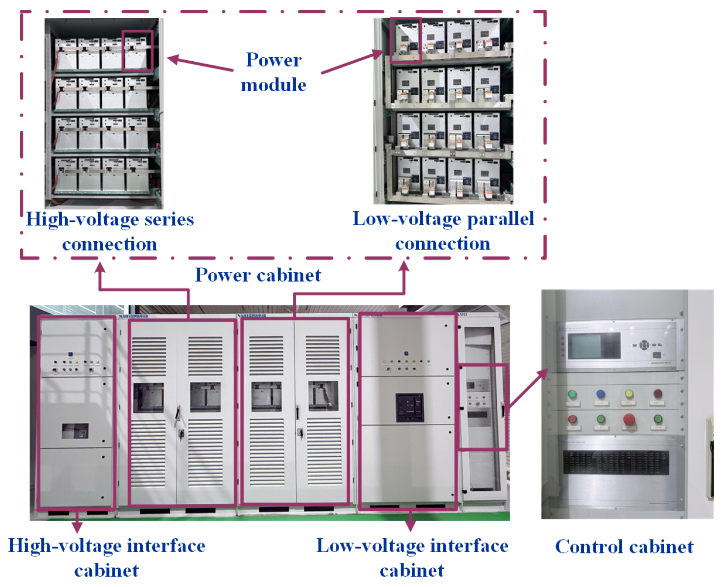
The SST, also referred to as the power electronic transformer (PET), is an intelligent power-conversion device. It relies on semiconductor devices, a high-frequency transformer (HFT), and advanced control techniques to convert high-voltage (HV) AC into low-voltage (LV) AC/DC and to enable bidirectional power flow [4,5]. Figure 1 illustrates the internal structure of the SST, consisting of the power cabinet and control cabinet. Compared with the conventional power-frequency transformer, the SST goes beyond the single operating mode based on electromagnetic induction. It integrates multiple functions, including electrical isolation [6], voltage conversion [7], and reactive power compensation. It therefore shows several notable features, such as a novel topology, flexible control, and a high degree of intelligence, as summarized in Table 1. Conventional transformers maintain high efficiency over a wide load range. While SSTs have lower device-level efficiency, their additional functions, such as power factor correction and unbalanced-current compensation, can reduce overall distribution-system losses. In addition, the SST is small and lightweight, has a reduced environmental impact, and offers a fast dynamic response. These advantages make it suitable for medium-voltage (MV) and HV, high-power applications. It can effectively meet the development needs of modern power systems and has become a key enabling device for future smart grids, renewable energy integration systems, and advanced power supply systems for emerging loads [8,9].
At present, SST research has attracted extensive attention both in China and worldwide [10,11,12]. Research institutions and companies around the world have invested substantial resources in key technological breakthroughs and have promoted their large-scale application. As a new type of intelligent energy conversion device, the SST can adapt to a wide range of application scenarios as well as power generation and supply systems. Its applications have become increasingly expanded into data centers, ultra-fast charging stations for electric vehicles, AC/DC hybrid distribution networks, and photovoltaic-storage DC flexible parks or microgrids [13,14,15]. Driven by the rapid growth in server power demand accompanying upgrades in computing infrastructure, the SST is expected to become a promising solution for next-generation power distribution systems in artificial intelligence data centers (AIDCs). In direct renewable-power supply scenarios, it can also enable efficient direct power delivery between renewable generation sources and load terminals, thereby reducing losses in intermediate conversion stages [16]. In addition to the functions of conventional transformers, the SST can also achieve real-time regulation of grid operation. This capability has attracted extensive attention from researchers and has promoted the increasing maturity of SST technology. As a result, the SST has shown strong application potential in fields that are highly sensitive to power quality, such as healthcare, banking, industry, defense, and aerospace. Their applications have also been gradually implemented in emerging fields such as rail transit and offshore wind power, bringing significant economic and social benefits for efficient energy utilization and green transformation [17,18].
Although SST technology has made substantial progress and its application scenarios have continued to expand, several urgent issues still remain in its practical deployment, including the application of new materials, control optimization, and cost reduction [14]. Against this background, a systematic review of SST topologies, core devices, and key technologies, together with a summary of current achievements and existing bottlenecks, has important theoretical and engineering value for promoting continuous technological breakthroughs and accelerating large-scale applications. Based on recent research progress and industrial practice in China and abroad, this paper presents a novel classification of SST development and provides a systematic review of SST topologies, core devices, control technologies, and emerging application scenarios. In particular, it distinguishes mainstream engineering topologies from emerging experimental designs and summarizes recent SST applications, offering a perspective beyond existing reviews.

2. Operating Principles and Development History of SSTs

2.1. Operating Principles of SSTs

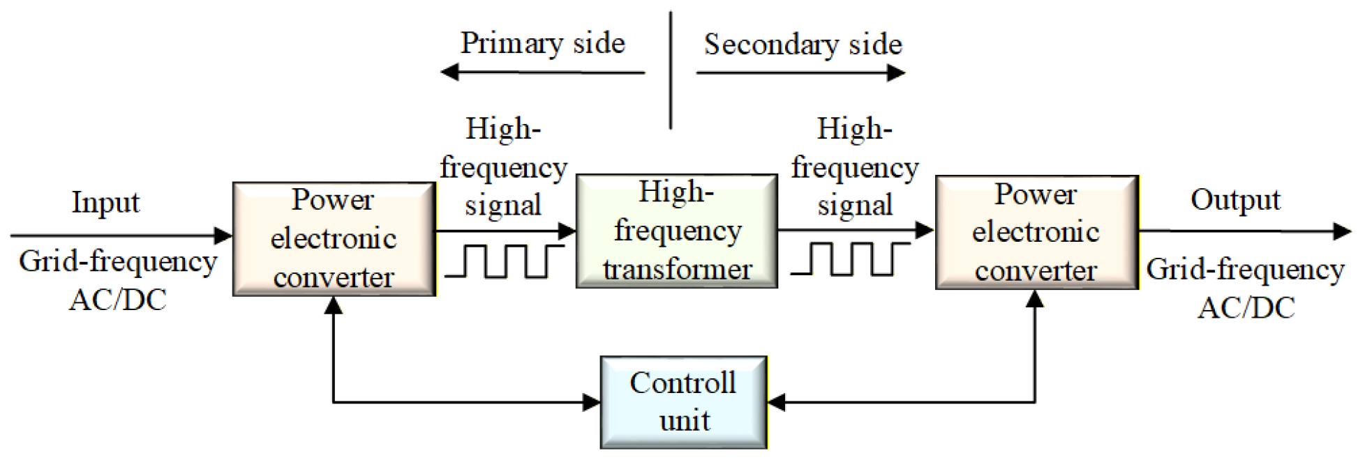
The SST consists of two key components: a power electronic converter and an HFT. Its basic operating principle is shown in Figure 2. The power electronic converter mainly suppresses harmonics, phase, and frequency. The HFT mainly provides isolation between the primary and secondary systems and performs voltage-level conversion. With appropriate control strategies, the SST can effectively improve power quality [7,19,20]. The maximum allowable temperature rise in the core and windings, together with the saturation flux density of the core material, are the main factors that determine transformer size. For a given voltage and allowable flux swing, increasing the operating frequency can reduce the required core size and thus the transformer volume [21].
Researchers in China and abroad have proposed various SST topologies. According to whether a DC link exists in the overall topology, these topologies can be divided into two main categories. One is direct AC/AC conversion, in which no DC link is involved during the conversion process [10]. The other is AC/DC/AC conversion, in which a DC link is included during the conversion process [22].
AC/AC-type SSTs have the advantages of small size, light weight, and simple structure. However, their controllability remains limited. The secondary-side waveform largely reproduces the primary-side waveform, which makes it difficult to effectively control the power flow through the power electronic transformer [23,24]. In contrast, AC/DC/AC-type SSTs require more devices and have a more complex structure. Nevertheless, they possess more complete control strategies. By using PWM modulation, they can effectively control the primary- and secondary-side voltage, current, and power of the transformer. They can also ensure excellent power quality, and the primary-side power factor is adjustable. Therefore, AC/DC/AC-type SSTs have strong practical value and are likely to become a major focus of future research for power system applications [2].

2.2. Evolution of SST Technology

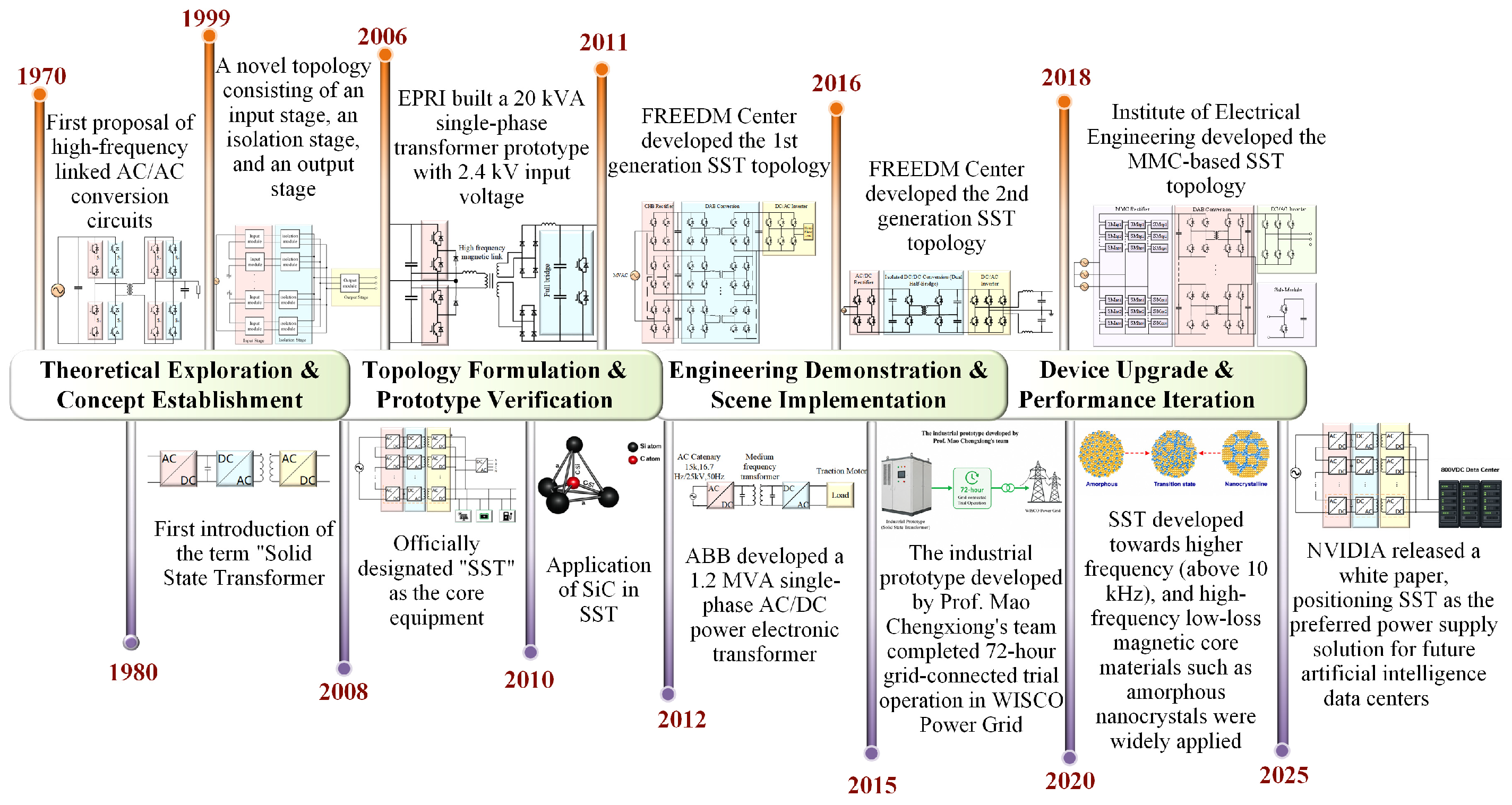
The evolution of SST technology has gone through four stages: theoretical exploration and concept establishment, architecture formation and prototype validation, engineering demonstration and scenario-based deployment, and device upgrading and performance iteration, as shown in Figure 3.

2.2.1. Stage of Theoretical Exploration and Concept Establishment

In the 1970s, the first HF-linked AC/AC conversion circuit was proposed, which is shown in Figure 4, marking the theoretical starting point of SST technology [25]. In 1980, the term “solid-state transformer” was formally introduced, which standardized the name of this technology [22]. Beginning in 1995, institutions such as the U.S. Navy and the Electric Power Research Institute in the United States carried out related studies on power conversion. They developed experimental prototypes based on AC/AC and DC/AC conversion and verified the technical feasibility of the concept. In contrast, these early prototypes were limited by device performance and still suffered from practical shortcomings, such as insufficient harmonic suppression and the lack of electrical isolation [26,40,41,42,43,44]. In 1999, a new topology consisting of an input stage, an isolation stage, and an output stage was proposed, marking the initial realization of the core SST architecture [22]. After that, the development of SSTs slowed because of limitations in power semiconductor devices. Even so, its theoretical framework basically took shape and laid the foundation for subsequent research.

2.2.2. Stage of Architecture Formation and Prototype Validation

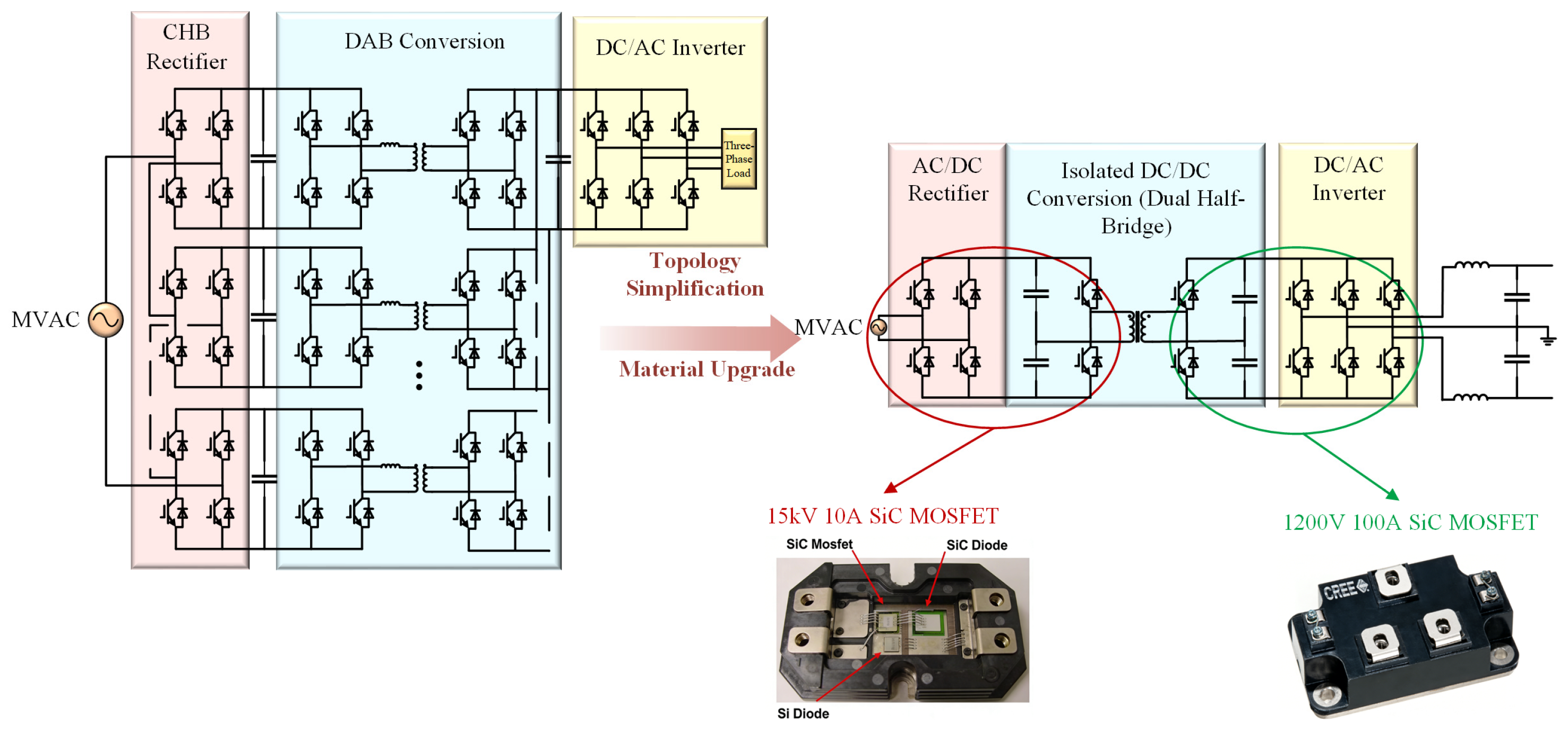
In 2008, the National Science Foundation Engineering Research Center for Future Renewable Electric Energy Delivery and Management Systems (FREEDM) in the United States formally adopted SST as the name of its core device and clearly defined the standard three-stage architecture [29]. With technological breakthroughs and wider application of wide-bandgap (WBG) semiconductor devices such as SiC and GaN, the FREEDM Center at North Carolina State University began to explore the use of SiC devices in SSTs [27,28,29]. Figure 5 compares the evolution from its first-generation topology to its second-generation topology. In the second-generation SST based on 15 kV SiC MOSFETs, the overall structure was simplified, and the switching frequency was increased to 20 kHz [2,30,31]. By this stage, the basic SST architecture had taken shape. However, because the fabrication cost, packaging, thermal management, and control coordination of 15 kV SiC MOSFETs had not yet matured, SST development remained largely at the prototype stage.

2.2.3. Stage of Engineering Demonstration and Application

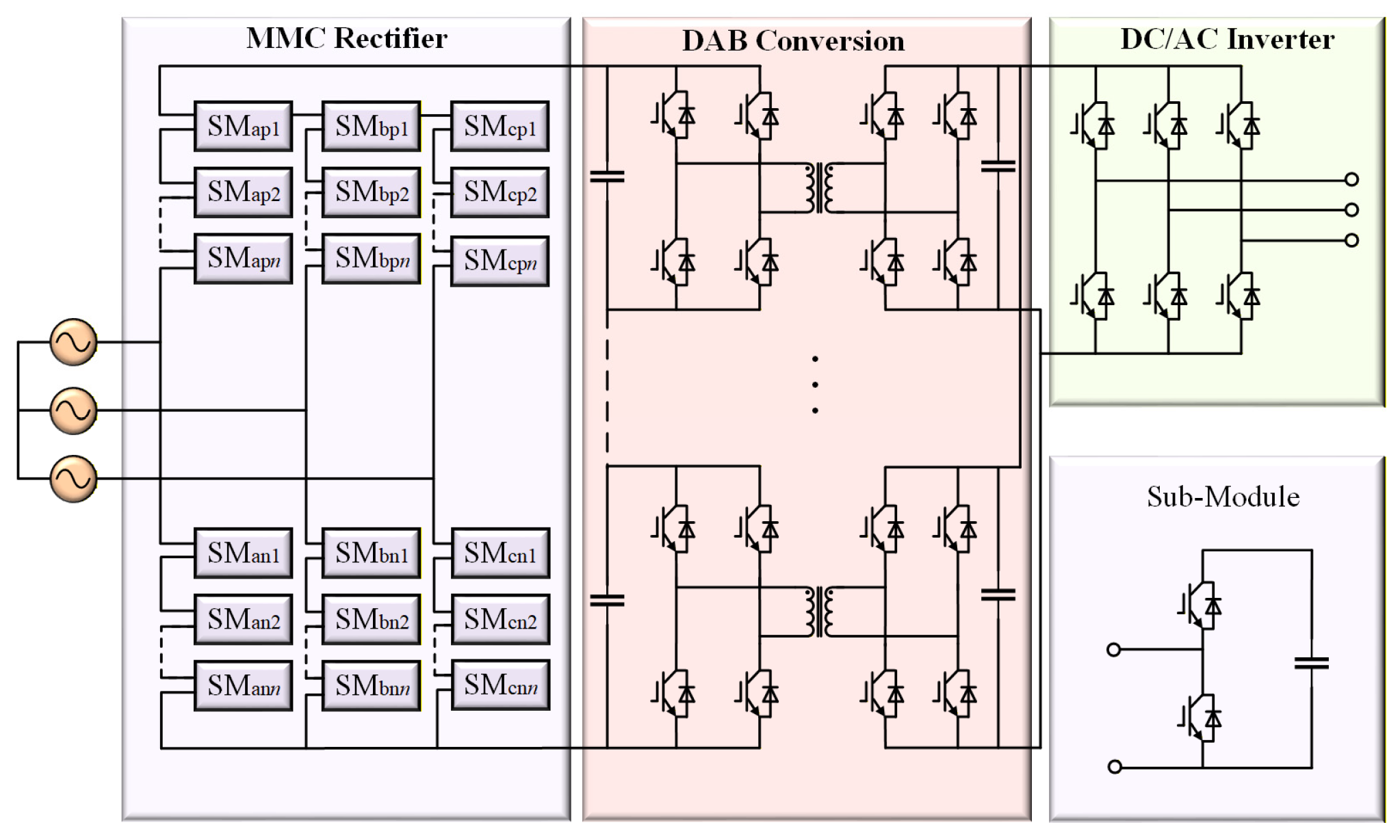
In 2014, ETH Zurich designed a 1 MVA SST to meet the demand for high-capacity SST in smart grids [32]. The rectifier stage and isolation stage adopted a diode-clamped three-level structure. This design increased the voltage withstand capability on the input side, greatly reduced the number of modules, and raised the switching frequency to 20 kHz [22]. In 2015, a 10 kV, 500 kVA industrial prototype developed by Professor Chengxiong Mao’s team at Huazhong University of Science and Technology completed trial operation in the Wuhan Iron and Steel grid. This was the first successful application of SSTs in an actual power system worldwide [45]. After that, research in China advanced rapidly. In 2018, Huazhong University of Science and Technology and the Institute of Electrical Engineering of the China Electric Power Research Institute jointly developed an MMC-based SST, as shown in Figure 6. In addition to conventional voltage transformation, it also provides power quality regulation. It is suitable for three-phase balanced load scenarios and has become a mainstream topology today [13,33,44]. During the same period, Zhejiang University proposed a topology integrating magnetic components and energy storage, which reduced photovoltaic power fluctuation to within ±5% [46]. As a result, SSTs have gradually moved from laboratory prototypes to field trial operation, and their engineering application and practical topologies have become increasingly mature.

2.2.4. Stage of Device Upgrading and Performance Iteration

Since the early 2020s, SSTs have developed toward higher switching frequencies, typically above 10 kHz. At the same time, third-generation semiconductor devices such as SiC devices have advanced rapidly, and HF, low-loss core materials such as amorphous and nanocrystalline materials have been widely applied in MV and LV AC/DC systems, distributed renewable energy systems, and emerging DC load hubs. These developments have steadily moved SSTs from the laboratory prototype stage toward applications featuring medium and high voltage levels, large capacity, and high power density [2,28,32,34,35,36,37]. In 2025, NVIDIA released the white paper “Building the 800 VDC Ecosystem for Efficient, Scalable AI Factories”, which identified the SST as a promising power supply solution for future artificial intelligence data centers [38]. This milestone marked a further expansion of SST application scenarios [39,40,46,47,48].

3. SST Topologies

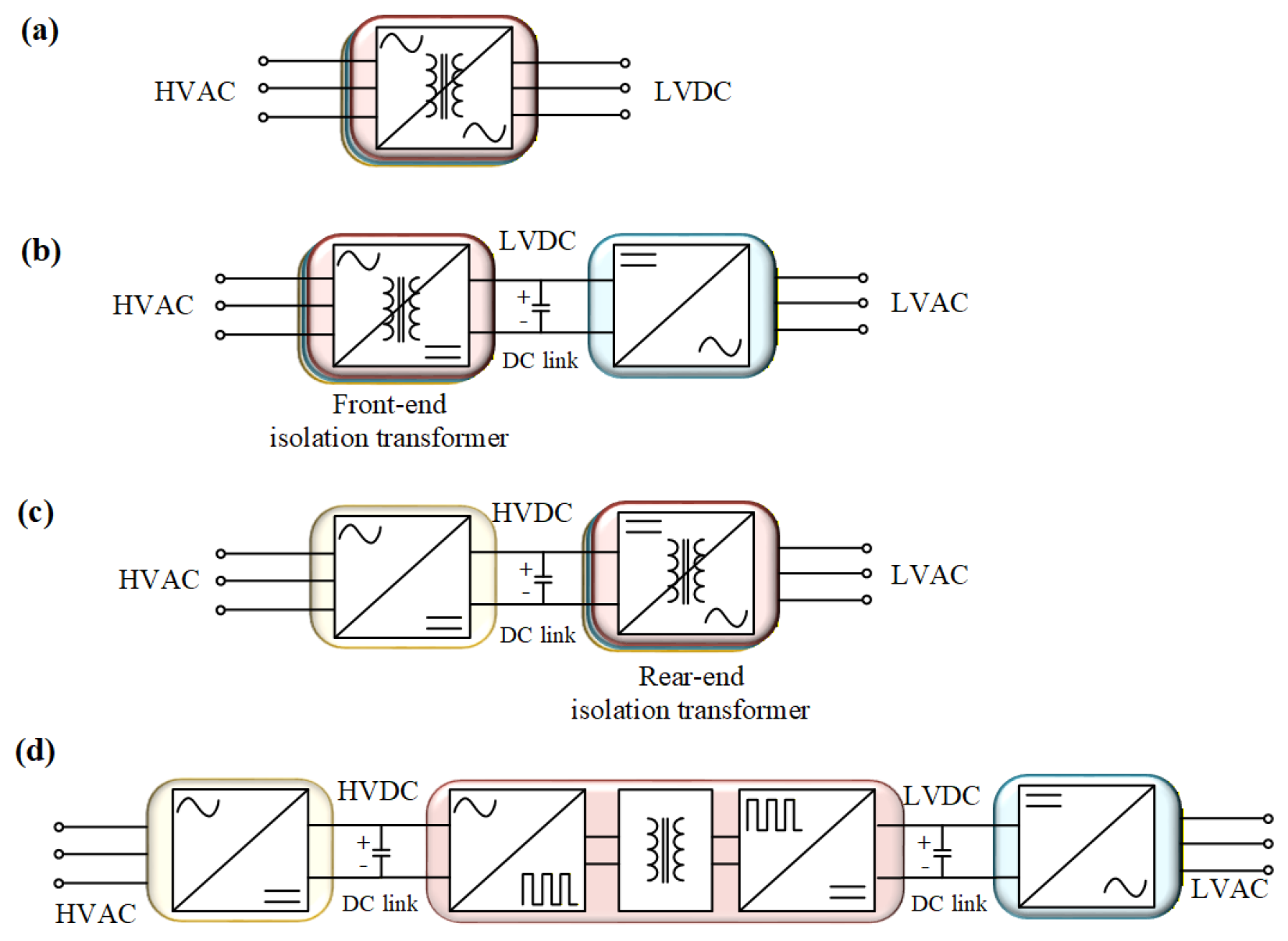
According to the number of power conversion stages, SST topologies can be classified into three categories: single-stage [49,50,51,52,53,54], two-stage [54,55], and three-stage structures [54,56,57,58]. Among them, the two-stage structure can be further divided into two types, namely, configurations with the isolation transformer placed before or after the conversion stage, as shown in Figure 7. Table 2 compares the characteristics and applications of different SST topologies and groups the two-stage and three-stage topologies into the multi-stage SST category for comparative purposes. The following section analyzes the typical SST structures.

3.1. Single-Stage and Two-Stage Topologies

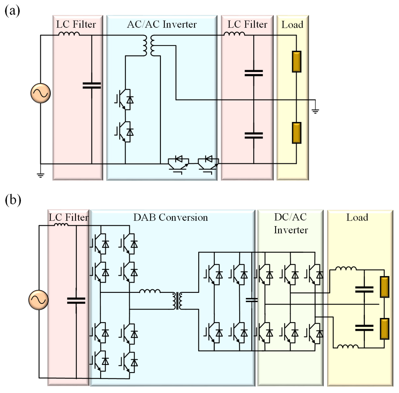
Figure 8a shows a typical single-stage AC/AC SST proposed in [26]. This topology has a simple structure, high conversion efficiency, and bidirectional power transfer capability. Its power transfer capability is three times that of a power-frequency transformer [59].
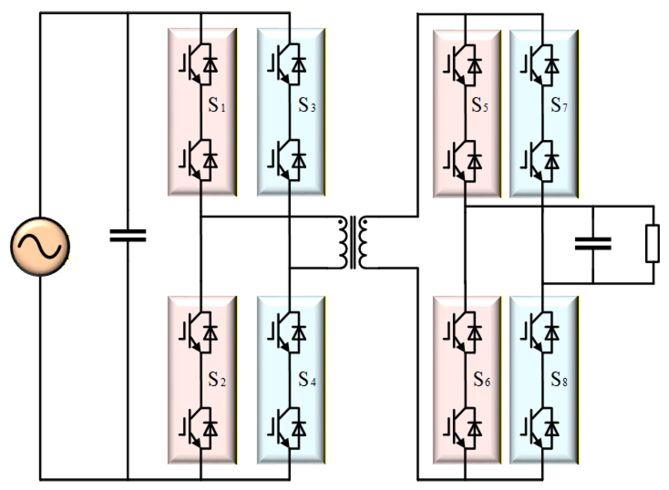
Figure 8b shows the two-stage single-phase SST topology reported in [8]. In this topology, the isolation stage adopts a dual active bridge (DAB) converter, which directly rectifies high-voltage AC and steps it down to LVDC. However, the average active power transferred by this structure is highly sensitive to leakage inductance, the current fluctuation is large, and the regulation capability on the LVDC side remains weak [2,7,59,60,61].
The single-stage SST topology has limited functionality. The grid side does not provide power factor correction, so this topology is only suitable for special LV, low-power applications and cannot be used in MV distribution networks. Although the two-stage SST simplifies the overall structure to some extent, it requires twice as many modules.
Because the ripple current is relatively large, a larger smoothing inductor is required, and the achievable power factor is limited. In terms of controllability, the two-stage SST is also inferior to the three-stage SST. In addition, the two-stage SST cannot simultaneously achieve independent optimal control of the grid side, load side, and isolation stage. It is therefore difficult to adapt to modular MV cascaded topologies and multiport applications. For these reasons, it has become less favored in recent engineering practice and frontier research.

3.2. Three-Stage Topologies

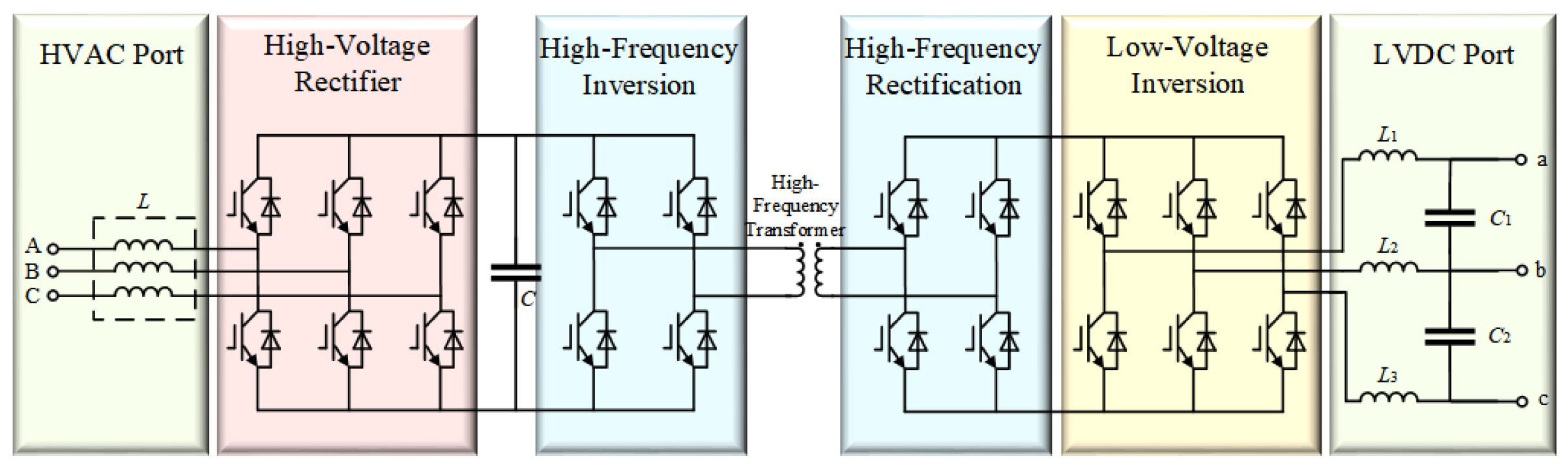
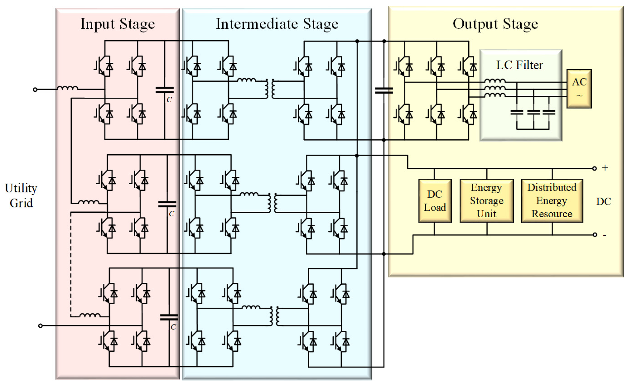
The three-stage SST structure generally includes several main components, such as converters, a DC bus, and an HFT. Its typical configuration is shown in Figure 9 [62,63,64].
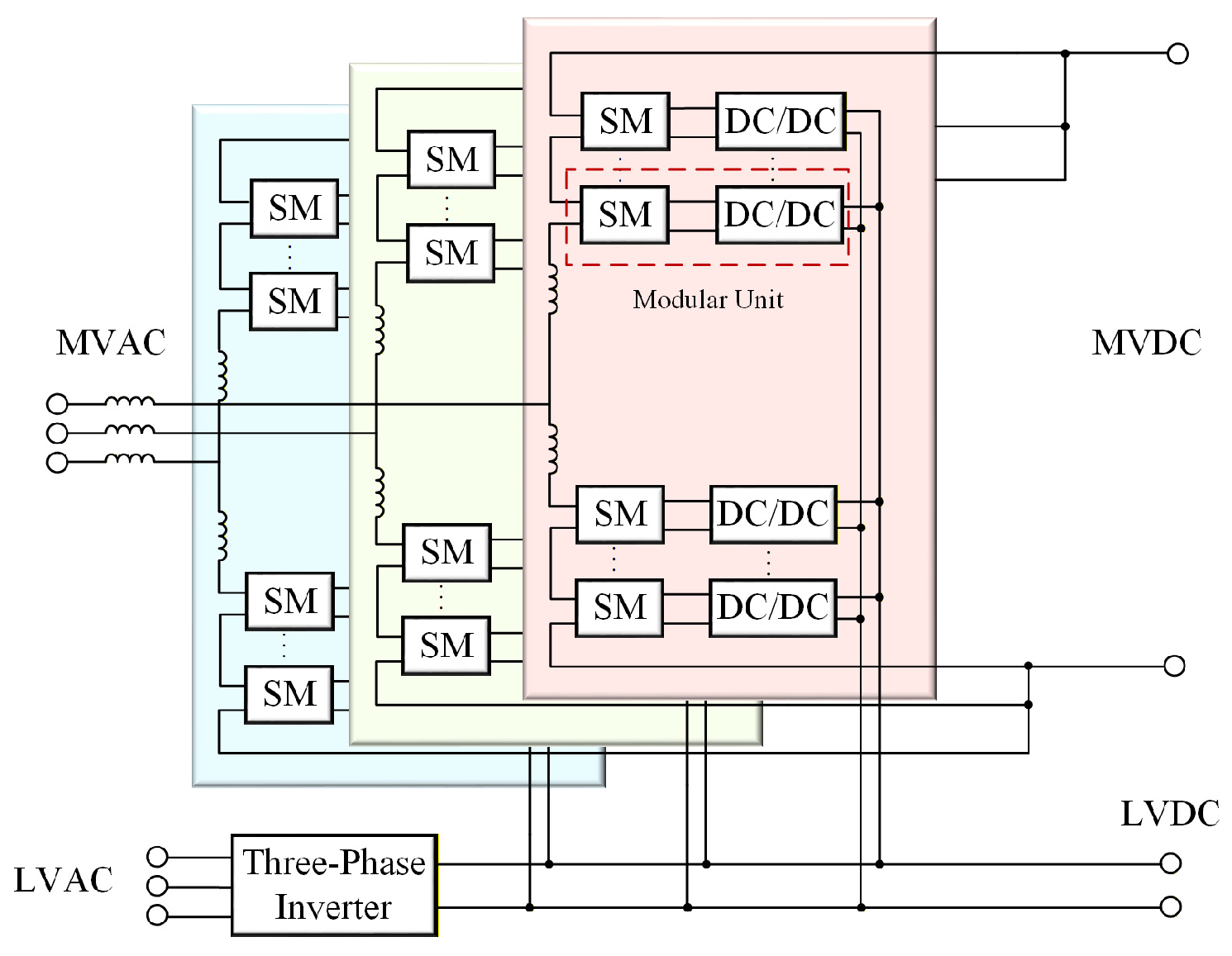
Although this structure is more complex than the AC/AC structure mentioned above, it provides more functions and a wider regulation range. For this reason, it has become the most widely discussed SST topology currently. The three-stage SST topology mainly has three typical forms: the cascaded H-bridge (CHB), the modular multilevel converter (MMC), and the neutral point clamped (NPC) topology [2,15,65].

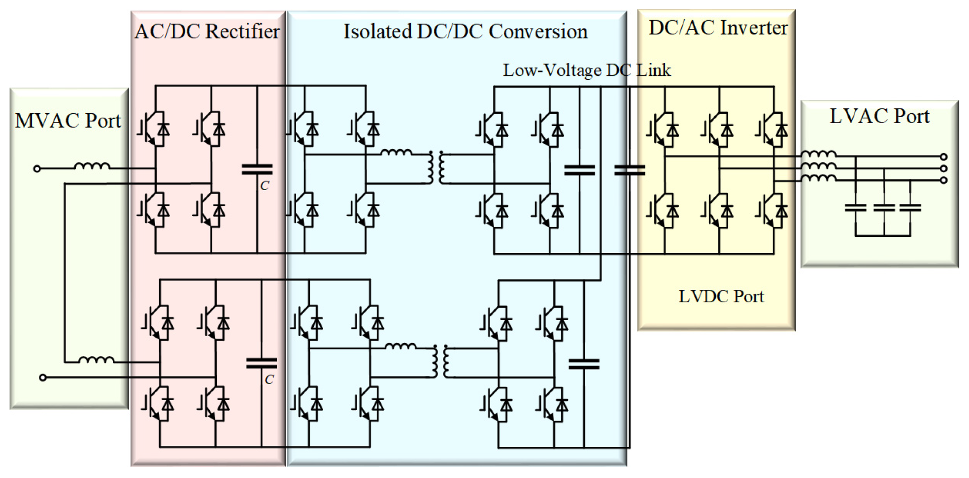
3.2.1. CHB-Based Topology

The CHB-based SST topology is shown in Figure 10. This topology has a high degree of modularity, is easy to expand, and has relatively simple control strategies. Therefore, it has attracted widespread attention from researchers [66]. However, this structure requires a large number of converters and HFTs, which makes its configuration more complex when it is applied in distribution network scenarios [67,68,69].

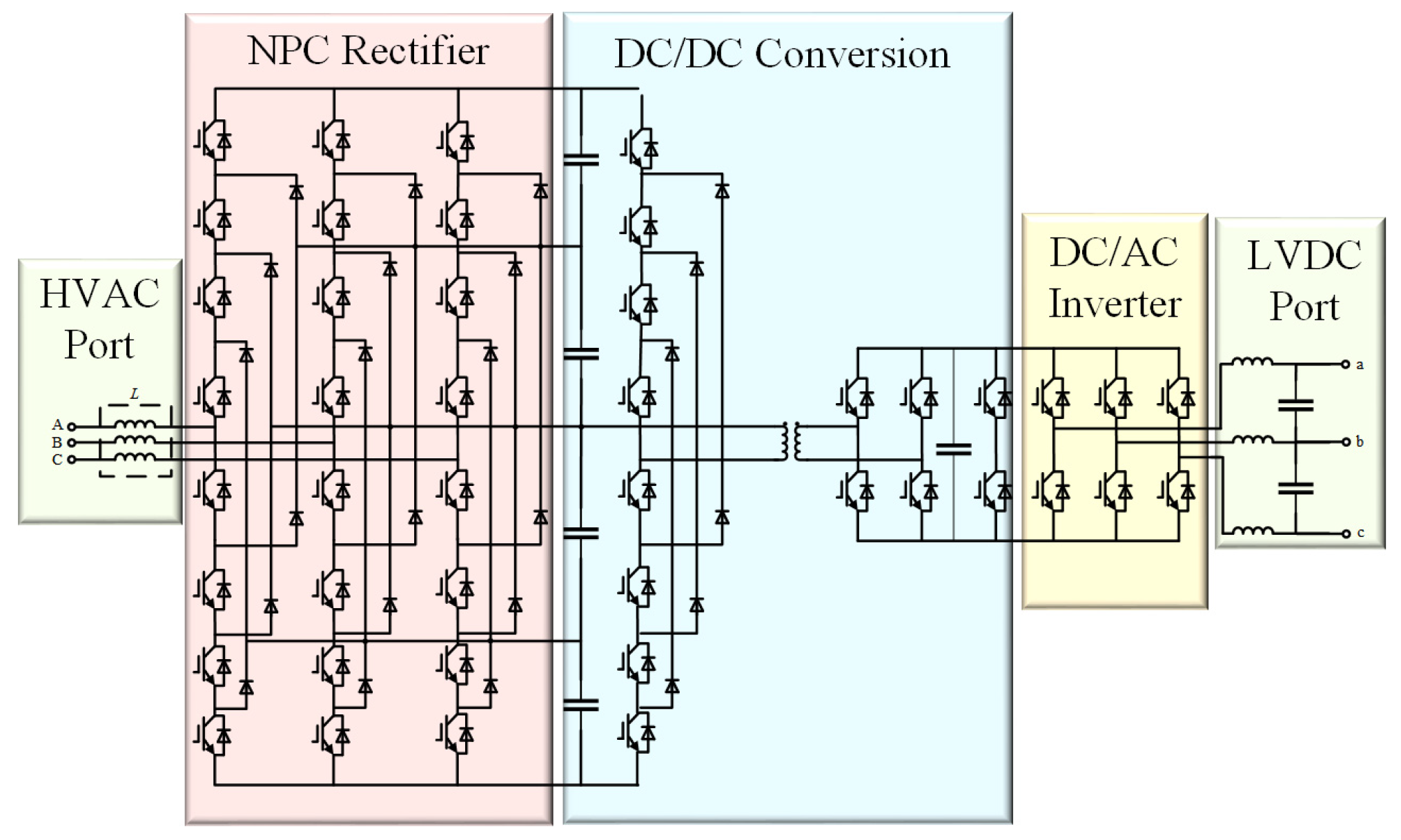
3.2.2. NPC-Based Topology

The SST topology based on the NPC structure is shown in Figure 11 [13,32]. Compared with the CHB and MMC topologies, the NPC topology has only one HV input port, which can greatly reduce the number of HFTs required. However, this structure is difficult to expand in a modular manner. It also requires a relatively large number of clamping diodes, and voltage-balancing control is more challenging [70].

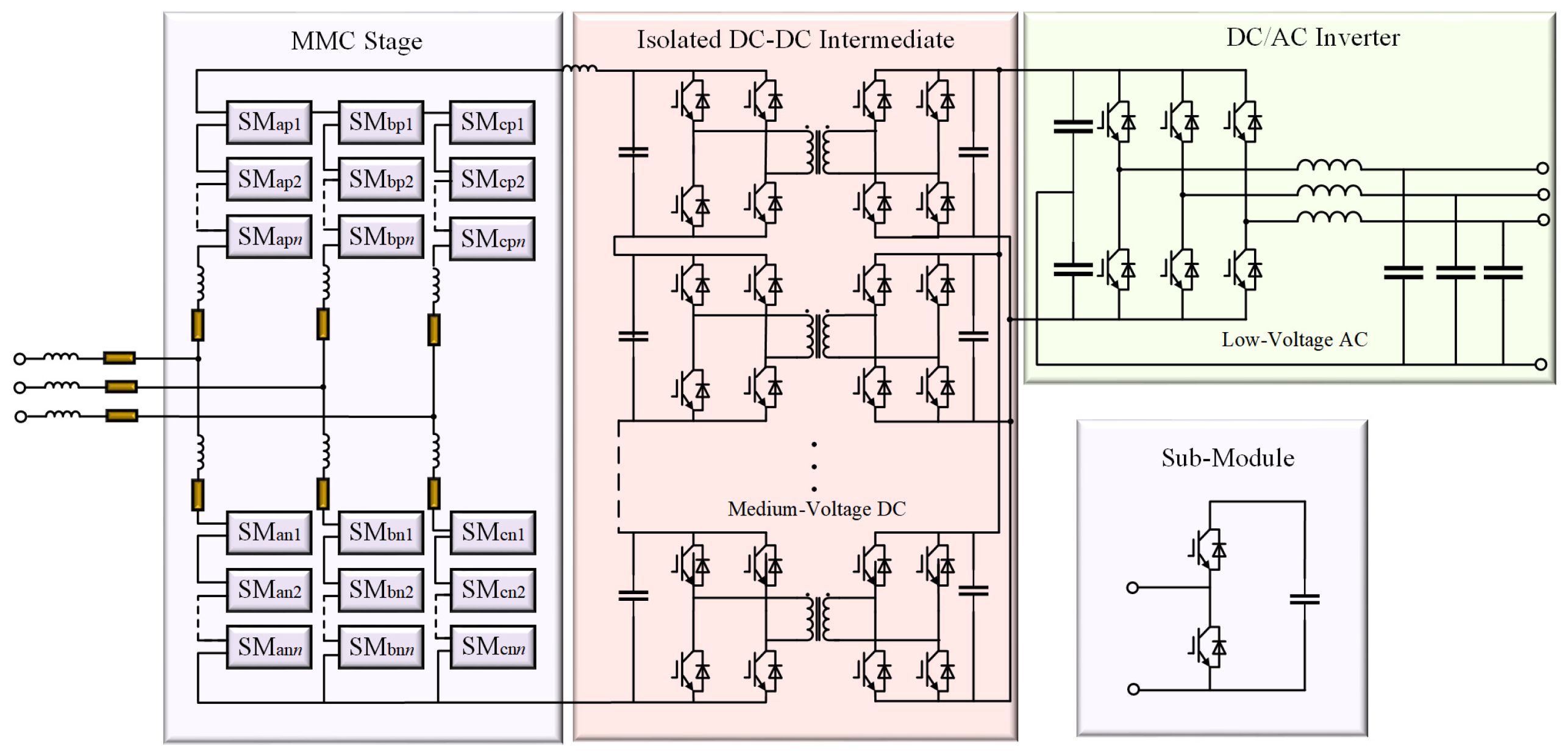
3.2.3. MMC-Based Topology

Figure 12 shows a typical three-stage SST topology based on the MMC structure [71,72]. Compared with the CHB structure, the MMC structure does not reduce the number of required power semiconductor devices. In contrast, it simplifies the internal control and gate-drive wiring of the submodules. Compared with the distributed layout of the CHB structure, it offers significant advantages in system integration and space utilization, which makes it more suitable for modular deployment in HV applications [70,73,74]. In addition, components such as the DC bus, DC sources, and DC loads in the MMC-based topology can be connected directly through the SST. This feature reduces the number of power conversion stages and improves conversion efficiency [75].
Because the three-stage SST has a DC bus, DC power sources such as photovoltaic generation systems can be directly connected to the system through the SST. This feature enables AC/DC hybrid integration and further improves energy conversion and utilization efficiency [8]. However, this structure is not well-suited for HV, high-power applications. A series connection of power devices on the HV side introduces voltage-balancing and reliability issues, which increase both cost and design difficulty. A comprehensive comparison of the CHB, MMC, and NPC topologies shows that the CHB topology has a simple structure, convenient scalability, and mature control. It also offers stronger redundancy and easier maintenance than the MMC topology, as well as better scalability than the NPC topology, without requiring a complex clamping structure. In MV distribution network scenarios, the overall performance of the CHB topology is more consistent with practical engineering needs. At the same time, the configuration of each stage in the CHB topology can be combined flexibly, which allows a variety of new topologies with stronger adaptability to be derived for different MV distribution network applications. Therefore, considering the characteristics of MV distribution networks and practical engineering requirements, the CHB topology has become the mainstream solution at present. It is more suitable for engineering deployment in MV scenarios and represents the engineering evolution direction of SST topologies in the MV field.

3.3. Emerging Topologies

At present, most emerging topologies are extensions of the three-stage SST. Figure 13 shows a cascaded multiport SST. By integrating a multi-winding HFT or parallel multi-module technology, it enables direct access to MV and HV grids while remaining compatible with various devices, including AC loads, DC sources, and energy storage systems. In this way, it serves as an energy router for AC/DC hybrid distribution networks [76,77,78,79]. In addition, this architecture combines the advantages of cascaded structures for MV and HV applications with the flexibility of multiport grid integration. It therefore performs much better than conventional transformers and standard SSTs in terms of system integration, power quality, operational reliability, and control flexibility. As a result, it has become a key development direction for the practical engineering application of SST technology.
The MMC-SST topology based on a switched-capacitor structure is shown in Figure 14. This topology consists of half-bridge MMC modules and a switched-capacitor interconnection circuit. The interconnection circuit includes a high-voltage AC bus, a synchronous transformer, and full bridges controlled by identical gate signals [80,81]. Voltage balancing of the submodule capacitors and the LVDC bus is achieved through the isolation transformer. Compared with conventional SSTs, the voltage ports in the isolation stage can adopt open-loop control. This advantage becomes more prominent when the number of LV ports is large, because the topology offers inherent voltage self-balancing capability [82].
In addition, the LF ripple currents of the submodules are also transferred to the high-voltage AC bus through the isolation transformer. Owing to the three-phase symmetry of the ripple currents, most ripple-current coupling is canceled naturally, which eliminates the need for dedicated ripple-current suppression and circulating-current suppression measures.
As summarized in Table 2, conversion efficiency is a key performance indicator for practical SST applications. The number of power conversion stages directly affects theoretical efficiency: single-stage SSTs require only one conversion and thus have the highest theoretical potential, two-stage SSTs introduce an additional isolated DC/DC stage with moderate efficiency reduction, and three-stage SSTs involve the most stages. However, practical efficiency is influenced by device voltage stress, high-frequency transformer design, soft-switching capability, and control complexity. Mature soft-switching techniques, such as DAB converters, and optimized modulation strategies enable high overall efficiencies in many medium- and high-voltage prototypes. Therefore, selecting SST topologies involves a trade-off between theoretical potential and practical feasibility.
A comparison of CHB, MMC, and NPC topologies reveals trade-offs among efficiency, control complexity, modular redundancy, scalability, and implementation cost. CHB topologies feature a clear structure, mature control strategies, and straightforward scalability, making them particularly attractive for medium-voltage applications. MMC offers superior modularity and high-voltage adaptability but requires more sophisticated control and communication systems, whereas NPC provides simpler control at the expense of limited scalability. Consequently, CHB remains one of the most mature and widely adopted SST topologies for medium-voltage applications. Emerging cascaded multiport SSTs and switched-capacitor MMC-SSTs are enhanced variants of conventional CHB- and MMC-based three-stage SSTs. Although prototype demonstrations have verified their feasibility, they remain largely at the experimental validation stage, while conventional CHB- and MMC-based SSTs have undergone more extensive engineering verification [77,79,80,81,82].

4. Core Components and Key Control Technologies of SSTs

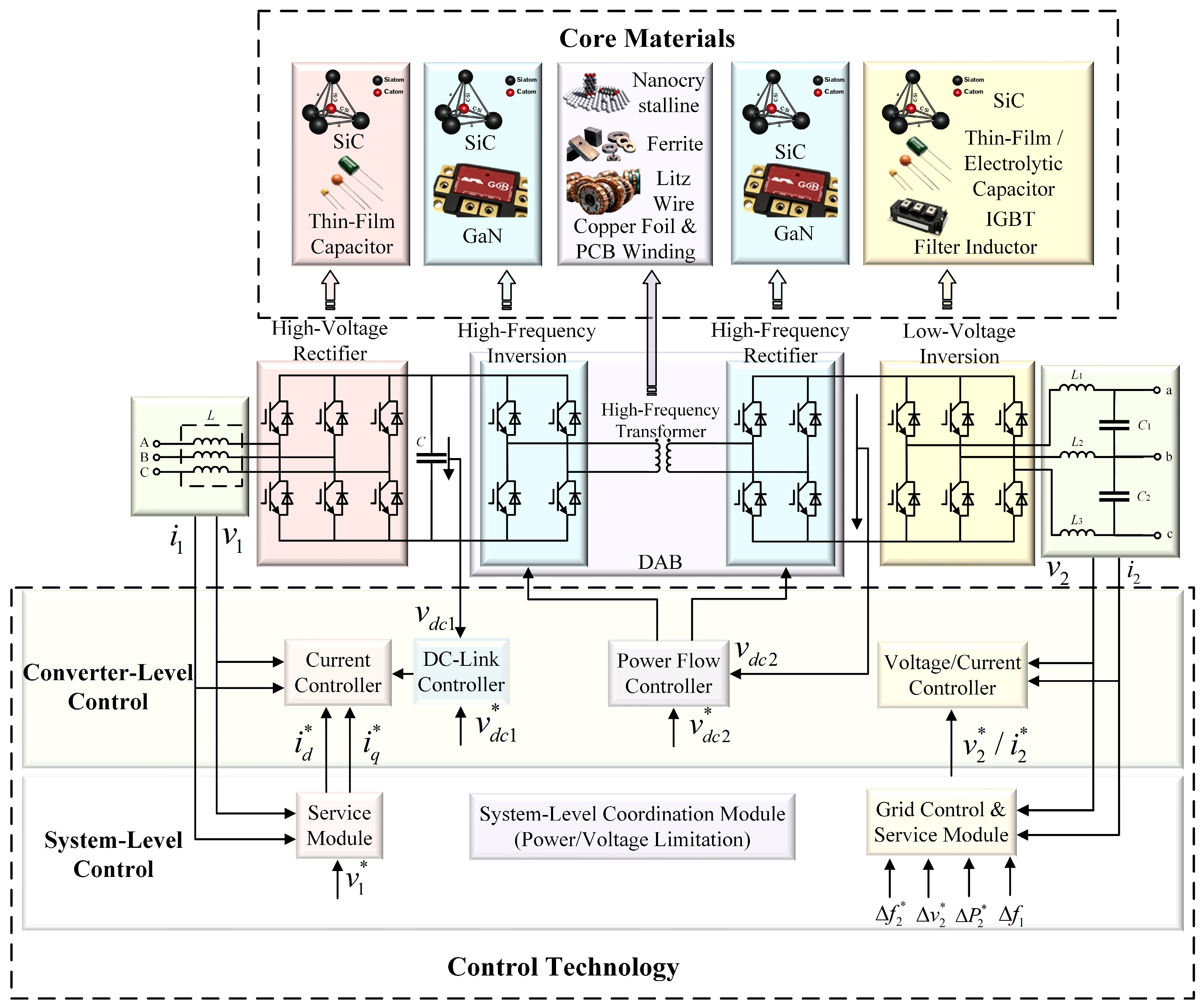
As discussed above, topologies developed on the basis of the three-stage SST have become the current mainstream. However, further performance improvement and practical engineering deployment are still constrained by the performance bottlenecks of core components and the challenges of key control technologies. As shown in Figure 15, this section focuses on the core hardware components and key control technologies that support SSTs, with the aim of providing technical support for their engineering application.

4.1. Core Components of SSTs

Power electronic converters and HFTs are the two core components of the SST. The key supporting devices in power electronic converters are power semiconductors, and their performance directly determines the switching characteristics and energy conversion efficiency of the converter. The magnetic components inside the HFT serve as the core elements for magnetic energy storage and conversion, and they play a decisive role in the power density, loss level, and operational stability of the transformer. On this basis, the following sections discuss in detail the characteristics, performance comparison, and applications of these two core components.

4.1.1. Power Semiconductor Devices

Power semiconductor devices are the core switching units of the SST. Parameters such as voltage rating, switching frequency, power loss, and temperature directly determine the operating frequency, energy conversion efficiency, and overall design of the SST [83,84]. For a long time, silicon-based power semiconductor devices have served as the technological foundation of power electronics because of their mature fabrication processes and low cost. As a result, they have been widely used in various power conversion systems. However, as SSTs have placed increasingly higher demands on high switching frequency and high-voltage operation, the physical limitations of silicon-based devices have become more apparent. These devices can no longer fully satisfy the requirements of SSTs for high efficiency and compact structure, and they have become an important bottleneck that constrains further SST development [66]. Table 3 compares the characteristics of power semiconductors based on different materials [85,86,87,88].
Compared with conventional silicon devices, WBG devices such as SiC and GaN offer major advantages, including higher breakdown electric field, better thermal conductivity, and faster switching speed. These advantages can significantly reduce conduction and switching losses, increase the operating frequency, and decrease the size of the HFT [88,89,90]. Their excellent electrical and thermal performance aligns closely with the core requirements of SSTs for high switching frequency and low loss. As these devices continue to develop toward higher voltage ratings, more mature fabrication processes, and lower cost, WBG devices such as SiC and GaN are expected to become the preferred device choice for the engineering application of SSTs.

4.1.2. HF Magnetic Components

The HFT is the core component that enables high power density and HF isolation in the SST. Among its key elements, the core material has a decisive influence on transformer performance, loss, and power density [91,92]. A comparison of the properties of different materials is presented in Table 4.
For HV, high-power transformers operating from 400 Hz to 20 kHz, the candidate core materials generally include silicon steel, ferrite, amorphous alloys, and nanocrystalline materials [2,93,94,95,96,97]. Silicon steel has high permeability and high saturation flux density. However, its loss becomes very large at HF. Ferrite has relatively low loss and low cost, but its saturation flux density is low, which results in a larger core volume. Iron-based amorphous alloys can provide a saturation flux density as high as 1.56 T, and their loss remains at a moderate level. They are therefore suitable for HFT cores operating from several hundred hertz to several kilohertz. However, when the operating frequency reaches several tens of kilohertz, the loss can only be reduced by lowering the flux density. Another option is cobalt-based amorphous material, which has much lower loss than iron-based amorphous material, but it also has a lower saturation flux density. Therefore, when power density and loss are considered together, nanocrystalline material becomes the preferred choice. Its saturation flux density is much higher than that of ferrite, and its loss is the lowest among these materials. However, nanocrystalline materials are usually more expensive, and their raw material is generally supplied as a coiled strip. As a result, additional processing and treatment are required in practical transformer design.

4.2. Key Control Technologies of SSTs

The control system of the SST needs to be designed hierarchically according to the functional roles of the three-stage topology. The input stage is responsible for grid connection and power quality regulation. The isolation stage is responsible for power transfer and DC-bus voltage stabilization. The output stage enables adaptation to the LV grid and provides active support. The coordinated interaction among these control layers allows the system to meet multiple requirements related to efficiency, reliability, and grid services. This section systematically reviews the core control technologies for the three-stage SST topology. It clarifies the mainstream control strategies, technical bottlenecks, and development directions at each stage, thereby providing theoretical support for the engineering application of SSTs.

4.2.1. Input-Stage AC/DC Control Technology

Using the mainstream CHB topology as an example, Table 5 compares different control methods [98]. Conventional linear control strategies have mature control structures, a high degree of engineering readiness, and stable performance under fixed-frequency conditions. However, they require targeted optimization under variable-frequency conditions [99,100]. To improve control performance in variable-frequency operation, sliding-mode control (SMC) has been widely applied to this type of converter. Compared with linear PI control, SMC provides better dynamic response and stronger disturbance rejection without increasing the computational burden [101]. It has therefore become an effective solution for variable-frequency scenarios. Model predictive control (MPC) has become a research hotspot in recent years because of its multi-objective optimization capability and strong adaptability to variable-frequency operation. However, the sharp increase in switching-state combinations caused by the cascaded multi-module structure of CHB leads to a substantial rise in computational complexity within the control loop, which limits its direct engineering application [102,103]. To address this issue, researchers have proposed lightweight strategies such as modulated MPC, switching-state preselection, multistage optimization, and predefined switching sequences. These methods reduce computational demand while effectively suppressing steady-state error, thereby promoting the practical application of MPC [104,105,106,107,108]. To meet the requirements for system inertia and primary frequency regulation under high penetration of renewable energy, grid-forming control has gradually been adapted to the CHB platform. By adopting grid-forming (GFM) strategies such as virtual synchronous generator (VSG) and droop control, the CHB-based SSTs can provide active voltage support, inertial response, and primary frequency regulation, effectively enhancing the stability and disturbance-rejection capability of the connected power grid [109,110,111]. It has therefore become a key issue in the design of this type of control strategy.
At present, conventional linear PI control remains the core strategy for engineering deployment because of its clear advantages in technical maturity and reliability. Lightweight model predictive control is rapidly moving toward practical implementation and is expected to become a mainstream next-generation solution. Grid-forming control, by contrast, represents the key development direction for power systems with high renewable energy penetration and is likely to become an essential control technology in future power systems. Overall, SST control is evolving toward higher performance, lower computational burden, and stronger grid-forming capability in order to meet the diverse demands of power-electronics-dominated power systems.

4.2.2. Isolation-Stage DC/DC Control Technology

The isolated DC/DC converter is the core stage in SSTs for achieving HF galvanic isolation and voltage conversion. Its main objective is to maintain the stability of the LVDC bus and to enable power transfer from the MV/HV DC side to the LVDC side. Among the mainstream topologies, DAB has been widely adopted. This topology consists of symmetrically configured fully controlled bridge legs and an HF magnetic coupling unit. By regulating the phase-shift angle between the primary- and secondary-side voltages of the transformer, it achieves precise control of both the magnitude and direction of the current [112]. This structure not only provides galvanic isolation between the primary and secondary sides but also establishes a bidirectional energy transfer path through HF carrier modulation [113].
From a modeling perspective, DAB dynamics are influenced by phase shift, transformer leakage inductance, port voltage ratio, load variations, and switching frequency. Average-value, small-signal, discrete-time, and generalized state-space models have been developed for controller design and stability analysis [114,115], supporting high-performance control and efficiency optimization.
Single-phase-shift (SPS) modulation remains the mainstream approach due to its simplicity and fast dynamic response, though it may induce circulating currents or reactive power under voltage mismatch or light load [116]. Multi-degree-of-freedom strategies, including dual-phase-shift (DPS), extended-phase-shift (EPS), triple-phase-shift (TPS), and asymmetric duty-cycle modulation, have been proposed to extend ZVS operation and reduce RMS current and reactive power [116,117].
In modular SSTs, multiple DAB cells require voltage balancing and power sharing control to prevent overvoltage, overcurrent, or thermal stress [118]. Efficiency can be further enhanced using extended soft-switching, minimum current-stress control, reactive power minimization, and coordinated parameter design [119].
Control architectures typically employ an outer-loop LVDC bus voltage controller combined with inner-loop power or current controllers. Beyond conventional PI control, advanced methods such as model predictive control (MPC), sliding-mode control (SMC), disturbance-observer-based control (DOB), adaptive control, and intelligent optimization have been applied to improve dynamic performance, robustness, and fault tolerance [120,121]. Closed-loop control is realized by a power flow controller, which takes the LVDC bus voltage and its reference value as inputs [36,62]. The operating characteristics of the DAB indicate that, under both forward and reverse power transfer modes, the system can be equivalently regarded as a combined inversion–rectification process, with a high degree of control flexibility [122].
At the lower level, control and modulation strategies are selected according to topology and operating conditions, including phase-shift, linearization, disturbance observer, and SMC approaches [123]. SPS control remains the practical engineering choice due to simplicity and fast response, while soft-switching techniques such as ZVS further improve conversion efficiency, reduce thermal stress, and extend device lifetime [61,124,125,126].
In summary, DAB-based isolated DC/DC converters have evolved into an integrated framework combining modeling, advanced modulation, voltage balancing, efficiency optimization, and multi-level control, achieving an optimized trade-off among efficiency, dynamic response, voltage/current sharing, reliability, and control complexity.

4.2.3. Output-Stage DC/AC Control Technology

The control mode of the LV-side DC/AC converter is determined by the application scenario of the system. It can operate in two basic modes: GFM and grid-following (GFL) [127]. In GFM mode, the converter needs to maintain the stability of its internal voltage phasor during the subtransient and transient periods. This function can be achieved through control methods such as VSG, dispatchable virtual oscillator control, and complex droop control [128,129,130,131]. In GFL mode, the control principle is similar to that used on the MV and HV sides. A current closed loop is adopted to achieve flexible regulation of active power, reactive power, and harmonic power. In addition, the LV grid control and service module can select signals such as active power deviation, frequency deviation, and voltage deviation as feedback variables or reference inputs according to operating requirements.
During grid-connected operation, GFL PI-based dual-loop current control is the dominant strategy because the structure is mature and highly reliable. In islanded and microgrid scenarios, VSG control and droop control of GFM have become the mainstream solutions, as they provide both inertia support and voltage–frequency stability. Owing to its diverse control schemes, scalability, and modular characteristics, the SST exhibits a high degree of flexibility. While performing the conventional functions of isolation and voltage transformation, it also provides dynamic grid services that are much faster than those of on-load tap changers, thereby meeting the diverse operational requirements of modern distribution networks.

5. Application Scenarios and Demonstration Projects of SSTs

5.1. Application Scenarios of SSTs

Owing to its efficient and flexible regulation capability, lightweight structure, and AC/DC conversion capability, the SST is mainly applied in high-density and high-reliability power supply scenarios. These applications include data centers, electric vehicle (EV) charging stations, renewable energy grid integration in future power systems, hybrid AC/DC distribution networks, microgrids, rail transit systems, and smart cities.

5.1.1. Data Centers

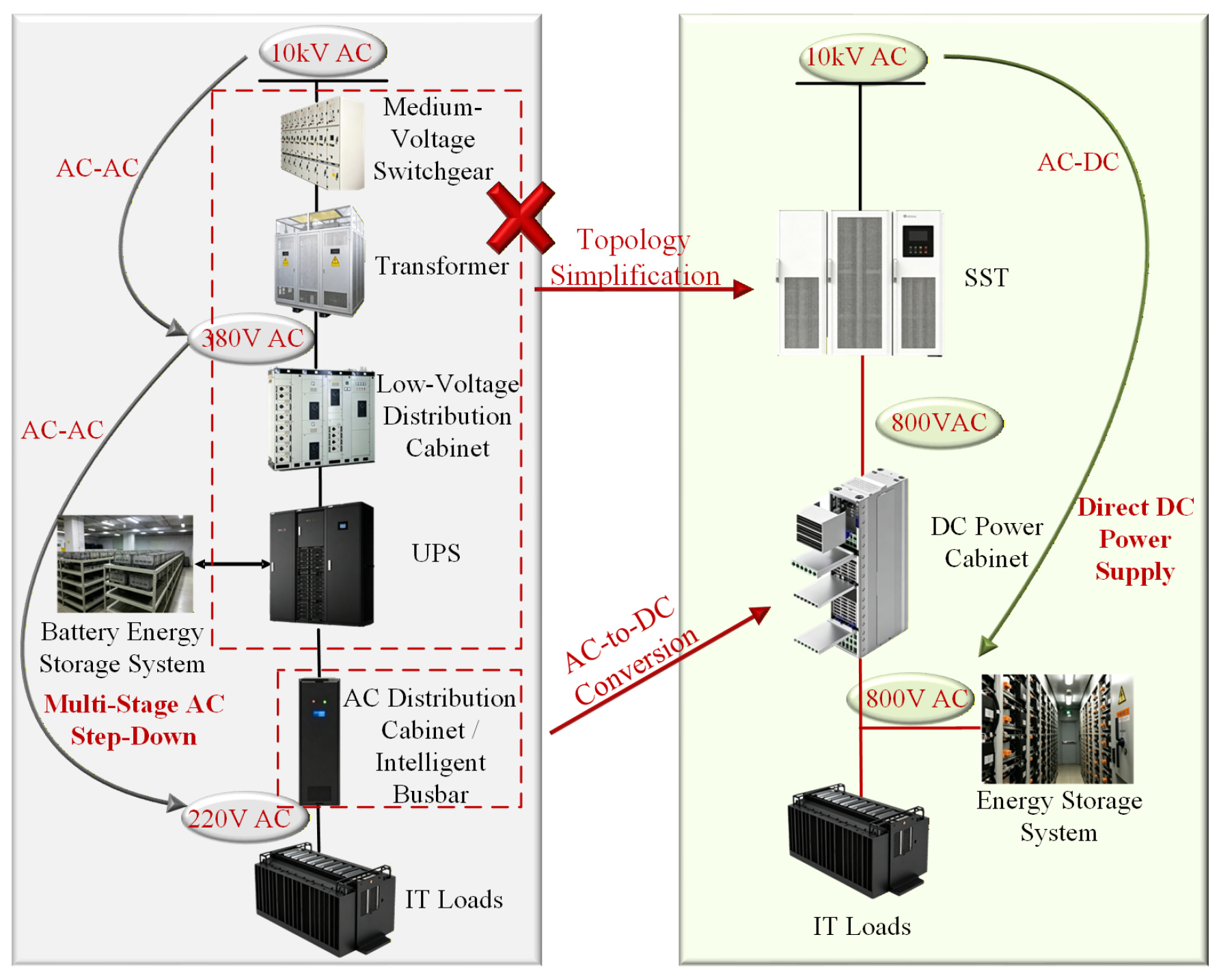
As computing infrastructure, data centers impose core requirements on their power supply systems, including high reliability, high energy efficiency, high power density, and high scalability. Conventional data centers usually adopt an AC distribution architecture based on an uninterruptible power supply (UPS) and a power-frequency transformer. However, this scheme has a complex structure, relatively low efficiency, large space occupancy, limited reliability, and high operation and maintenance costs. In addition, the 220 V AC architecture is not well-suited to distributed energy resources such as photovoltaics, energy storage systems, and fuel cells. The integration of multiple energy flows therefore requires additional power conversion equipment, which further limits system scalability. As shown in Figure 16, by replacing both the UPS and the distribution transformer, the SST integrates voltage conversion, galvanic isolation, power quality conditioning, coordinated energy storage, and multiport access into a unified platform. Through medium-voltage power supply and facility-level DC distribution, it simplifies the power supply architecture while simultaneously achieving high reliability, high efficiency, and high power density. As a result, it aligns closely with the core requirements of modern data centers.

5.1.2. Charging Stations

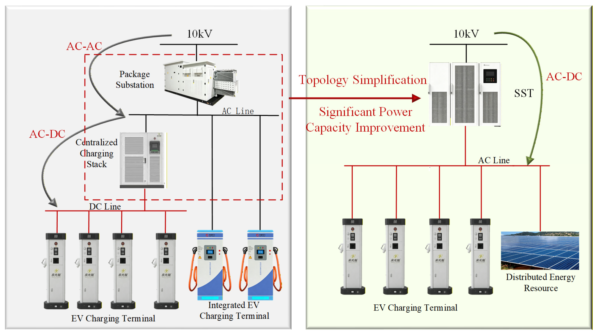
Conventional charging stations usually adopt architectures based on box-type substations, charging cabinets, or high-power DC EV chargers combined with charging interfaces. However, these solutions suffer from large volume, low conversion efficiency, and complex system architecture, and they are difficult to adapt to the capacity expansion required by ultra-fast charging [132]. As illustrated in Figure 17, the SST significantly reduces both size and weight while increasing efficiency to above 98%. It also supports millisecond-level power regulation and bidirectional energy flow. These features enable it to respond rapidly to time-varying grid demand and help achieve peak shaving and valley filling, making it well-suited to the requirements of modern charging and battery-swapping systems.

5.1.3. Smart Distribution Grids and Microgrids

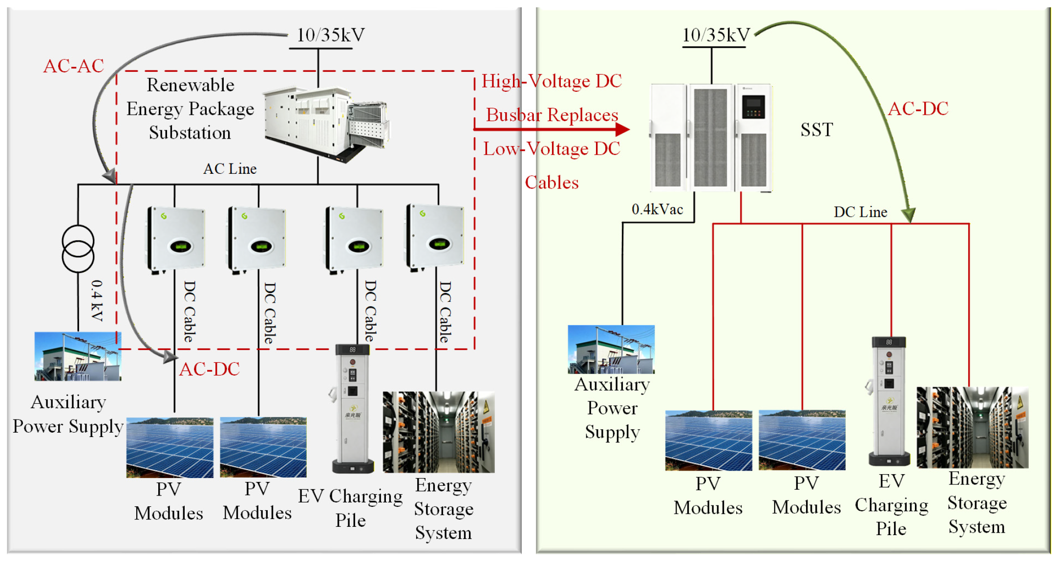
In conventional renewable energy grid-integration schemes, distributed generators, energy storage systems, and DC loads all need to be connected to the AC bus through inverter stages. As depicted in Figure 18, the SST adopts a DC-bus-based architecture, which simplifies the system structure and enables flexible and rapid integration of distributed resources through DC interconnection. This approach supports efficient local consumption and surplus power feed-in, reduces operating losses, and improves the renewable energy hosting capacity [133]. In this context, the SST can serve as an energy router. It provides an efficient and intelligent interface for distributed energy sources such as solar and wind power, while also establishing a stable and reliable DC microgrid.

5.1.4. Military and Specialized Industrial Applications

Military sectors such as electrified transportation platforms, naval vessels, and aircraft impose stringent requirements on the size, weight, and power quality of power supply equipment. By using compact and weight-optimized SSTs for power transmission, these systems improve both design flexibility and energy utilization efficiency. In superconducting distribution systems for electric aircraft propulsion, the SST provides a compact and lightweight power transmission solution and increases design flexibility. In shipboard DC distribution systems, SST-based DC distribution improves overall energy efficiency.

5.2. Demonstration Applications of SSTs

Since 2011, SSTs have gradually entered engineering applications and practical deployment [39,95,134,135,136,137,138,139,140,141,142,143,144]. Table 6 summarizes research and industrial projects worldwide that have advanced the development of SSTs.
SSTs are progressively transitioning from pilot demonstrations to large-scale applications. Their value has become increasingly evident in enhancing grid flexibility, facilitating renewable energy integration, supporting power supply for high-density loads, and advancing transportation electrification, making them one of the key enabling technologies for the future Energy Internet and next-generation power systems.

6. Challenges Facing SSTs

With their flexible topological structures and coordinated multiport control capability, SSTs have become one of the core enabling devices for driving the transformation of distribution networks toward higher efficiency and intelligence. However, to progress from laboratory-scale prototype validation to engineering implementation and large-scale commercialization, SSTs still need to overcome critical bottlenecks in both technological development and practical application [8].

6.1. Technical Challenges

The topological architecture of SSTs and their device-level operating characteristics subject them to reliability and lifetime challenges that are far more severe than those of conventional transformers. The main technical difficulties are concentrated in two dimensions: hardware and control.
At the hardware level, MV and HV SSTs generally adopt multilevel or three-stage topologies, in which a large number of power switching devices, capacitors, inductors, and control modules are integrated through the series connection of multiple cells and the parallel connection of multiple modules. As a result, the number of potential failure points increases dramatically, and a fault in any single device may cause system shutdown or even cascading failures. Meanwhile, although WBG devices such as SiC and GaN have provided the basis for HF operation, the switching losses generated at high frequencies, together with local hot spots caused by dense device packaging, have made thermal management a critical challenge. Existing air-cooling and liquid-cooling solutions still struggle to achieve precise temperature regulation under extreme operating conditions, thereby increasing the risks of device aging and thermal runaway. In addition, the multiport and multilevel characteristics of SSTs have led to fault modes that are increasingly diverse and strongly coupled. Fault signatures are easily disturbed by HF harmonics, while technologies for multi-fault coupled identification and early warning of weak incipient faults in complex topologies have not yet matured. The lack of a standardized fault diagnosis framework has therefore constrained the application of SSTs in scenarios requiring high reliability and long service life.
At the control level, the intrinsic nature of SSTs as “power electronic transformers” has fundamentally transformed their control strategies. Their multiport and multilevel characteristics impose extremely stringent requirements on response speed, robustness, and stability. In terms of control objectives, SSTs must simultaneously satisfy multiple tasks, including grid-side power quality regulation, precise load-side power supply, and energy management on the storage side. These objectives are strongly coupled, which makes coordinated optimization highly challenging. From the perspective of topology, multilevel and multimodule parallel structures have caused the controlled plant to exhibit high-dimensional, nonlinear, and strongly coupled characteristics, requiring effective solutions to issues such as capacitor voltage balancing and current sharing among modules. HF operation has also challenged conventional linear control methods, whereas advanced nonlinear algorithms still face bottlenecks related to high computational complexity and the difficulty of simultaneously ensuring accuracy and real-time performance in embedded controllers. Furthermore, operating conditions such as weak-grid impedance fluctuations and abrupt load variations have further increased the difficulty of control, and existing adaptive algorithms still need improvement in balancing dynamic response and system stability.

6.2. Application Challenges

The practical implementation of SSTs faces several key bottlenecks that limit large-scale commercialization, including high system cost, thermal management, electromagnetic compatibility (EMC), reliability, and high-frequency magnetic integration.

6.2.1. System Cost

High cost remains the primary barrier to SST commercialization, with the main contributors being power semiconductor devices and high-frequency transformers (HFTs). SST operation relies on wide-bandgap semiconductors such as SiC and GaN to achieve high-frequency, high-efficiency performance. However, the fabrication and packaging processes for these devices are complex, and the cost of individual devices far exceeds that of conventional silicon-based components. Moreover, multilevel topologies commonly used in medium- and high-voltage SSTs require dozens or even hundreds of power devices connected in series and parallel, significantly driving up system cost. HFTs, operating at kilohertz-level switching frequencies, require low-loss soft magnetic cores such as ferrite or nanocrystalline alloys, and windings typically use Litz wire to reduce skin and proximity effects. These materials and structures are substantially more expensive than silicon steel laminations and conventional copper windings used in power-frequency transformers. The high degree of customization and difficulty in mass production further reduces the cost competitiveness of SSTs.

6.2.2. Thermal Management

Thermal management is a critical challenge that directly affects power density, reliability, and device lifetime. High-frequency switching in SSTs leads to power losses concentrated in small chip-level regions, producing extremely high heat flux densities. The compact design required for high power density compresses available cooling space, making traditional air cooling insufficient. SSTs combine components with differing thermal characteristics, including power devices, HFTs, and filter capacitors, and multi-module cascaded structures can result in uneven thermal distribution and localized hotspots, accelerating device aging or triggering thermal runaway. Advanced cooling techniques such as liquid cooling, heat pipes, and immersion cooling can enhance thermal performance but increase system complexity, volume, and cost, creating a trade-off between thermal performance, compactness, and overall cost.

6.2.3. EMC

EMC is another major technical challenge in SST engineering. High dv/dt and di/dt generated by high-frequency switching, coupled with leakage flux from HFTs and surrounding metallic structures, are the primary sources of electromagnetic interference. EMC mitigation in SSTs remains challenging because high-frequency switching generates steep voltage and current transitions, and leakage flux from HFTs couples with nearby metallic structures. Conventional filters are limited in effectiveness, and improving suppression typically requires larger, heavier components, which conflicts with SST miniaturization and lightweight goals. The multiport architecture introduces multiple interference paths, while EMC characteristics strongly depend on topology, control strategy, switching conditions, and operating scenarios. Coordinated operation of multiple converters can further exacerbate system-level EMC issues, making comprehensive and standardized EMC design difficult.

6.2.4. Reliability and High-Frequency Magnetic Integration

SST reliability is inherently challenged by its complex structure and high-frequency operation. The system includes numerous power devices, capacitors, inductors, and control chips, and failure of any component can lead to system shut-down. Serial reliability decreases exponentially with the number of components, making multi-module cascaded medium- and high-voltage SSTs inherently less reliable than simpler low-frequency transformers. High-frequency operation accelerates device aging, and long-term reliability data for wide-bandgap devices under high-frequency and high-temperature conditions remain limited. Insulation and magnetic material degradation under high-frequency alternating fields are also not fully understood. The system’s resilience under grid faults or lightning strikes requires further study. High-frequency magnetic integration, which consolidates multiple inductors and transformers into a single magnetic core, can significantly reduce size and weight but introduces challenges such as magnetic coupling interference, complex multi-winding designs, and higher local losses, thereby increasing thermal management complexity.
In summary, the engineering deployment of SSTs requires comprehensive trade-offs among cost, performance, volume, reliability, and thermal and electromagnetic considerations. Future research should focus on cost-effective wide-bandgap devices, advanced EMC mitigation, efficient thermal management technologies, and high-reliability magnetic integration to accelerate SST maturity and enable large-scale commercialization.

7. Conclusions and Future Outlook

SSTs are driving the evolution of power systems from traditional passive networks toward greater flexibility and intelligence. This review has summarized their operating principles, topological variations, key component considerations, control technologies, and representative applications. Currently, SSTs are transitioning from laboratory prototypes to practical engineering demonstrations.
(1)
Device level
The widespread adoption of HV SiC and GaN WBG devices is enabling improved efficiency and power density under high-frequency, high-voltage, and high-temperature conditions. Three-stage SSTs, typically using CHB or MMC topologies, are widely adopted in medium-voltage prototypes, with several engineering demonstrations reported, while full-scale commercial deployment remains limited.
(2)
System level
Modular multi-level and multiport architectures, including MMC and CHB topologies, are approaching industrial feasibility, providing flexible AC/DC interfacing and power-flow control.
(3)
Control level
Conventional linear control has gradually been giving way to intelligent control. Control architectures based on model predictive control, reinforcement learning, and digital-twin technologies are being explored to improve multi-objective optimization, adaptive operation, condition monitoring, and predictive maintenance under complex operating conditions involving multiple ports, multiple objectives, and multiple time scales, while also enhancing the system’s capabilities for fault self-awareness, self-diagnosis, and self-recovery. These artificial intelligence and digital-twin-based methods, however, are still mainly in research and pilot implementation stages. SSTs are currently expanding from low- and medium-voltage scenarios into key application areas such as MV and HV distribution networks, data center power supply, and ultra-fast charging stations, where they are being explored as alternatives to conventional power-frequency transformers in selected scenarios.
In the future, as the cost of WBG devices declines further, magnetic integration technologies mature, and intelligent control algorithms are implemented in practical engineering systems, SSTs are expected to become key hub devices in next-generation power-electronics-based power systems under conditions of high penetration of distributed energy resources and increasing grid digitalization.

Author Contributions

Conceptualization, J.Z. and C.W.; methodology, J.Z.; validation, J.Z., D.W. and Y.C.; formal analysis, J.Z.; investigation, J.Z.; resources, C.W.; data curation, J.Z.; writing—original draft preparation, J.Z.; writing—review and editing, C.W., D.W., Y.C., S.L., T.G. and X.L.; visualization, J.Z.; supervision, C.W.; project administration, C.W.; funding acquisition, C.W. All authors have read and agreed to the published version of the manuscript.

Funding

The authors gratefully acknowledge financial support from the Smart Grid-National Science and Technology Major Project (2025ZD0806000).

Data Availability Statement

No new data were created in this study. Data sharing is not applicable to this article.

Conflicts of Interest

Author Jiatian Zhang, Chuanxin Wen, De’an Wang, Yonghua Chen, Shaohua Liu, Tian Gao, and Xiang Li were employed by the company Nari Technology Co., Ltd. The authors declare that this study received funding from the Smart Grid-National Science and Technology Major Project (2025ZD0806000). The funder was not involved in the study design, collection, analysis, interpretation of data, the writing of this article or the decision to submit it for publication.

References

  1. De Almeida, A.; Santos, B.; Martins, F. Energy-efficient distribution transformers in Europe: Impact of Ecodesign regulation. Energy Effic. 2016, 9, 401–424. [Google Scholar] [CrossRef] [Scilit]
  2. She, X.; Huang, A.Q.; Burgos, R. Review of Solid-State Transformer Technologies and Their Application in Power Distribution Systems. IEEE J. Emerg. Sel. Top. Power Electron. 2013, 1, 186–198. [Google Scholar] [CrossRef] [Scilit]
  3. Hamed, H.A.; Abdou, A.F.; Acharya, S.; El Moursi, M.S.; El-Kholy, E.E. A Novel Dynamic Switching Table Based Direct Power Control Strategy for Grid Connected Converters. IEEE Trans. Energy Convers. 2018, 33, 1086–1097. [Google Scholar] [CrossRef] [Scilit]
  4. Hamed, H.A.; Abdou, A.F.; Bayoumi, E.H.E.; El-Kholy, E.E. A Fast Recovery Technique for Grid-Connected Converters After Short Dips Using a Hybrid Structure PLL. IEEE Trans. Ind. Electron. 2018, 65, 3056–3068. [Google Scholar] [CrossRef] [Scilit]
  5. Battal, F.; Balci, S.; Sefa, I. Power electronic transformers: A review. Measurement 2020, 171, 108848. [Google Scholar] [CrossRef] [Scilit]
  6. Cervero, D.; Fotopoulou, M.; Munoz-Cruzado, J.; Rakopoulos, D.; Stergiopoulos, F.; Nikolopoulos, N.; Voutetakis, S.; Sanz, J.F. Solid State Transformers: A Critical Review of Projects with Relevant Prototypes and Demonstrators. Electronics 2023, 12, 931. [Google Scholar] [CrossRef] [Scilit]
  7. Predescu, D.M.; Roșu, Ș. Solid-State Transformers: A Review—Part I: Stages of Conversion and Topologies. Technologies 2025, 13, 74. [Google Scholar] [CrossRef] [Scilit]
  8. Mollik, M.S.; Hannan, M.A.; Reza, M.S.; Rahman, M.S.A.; Lipu, M.S.H.; Ker, P.J.; Mansor, M.; Muttaqi, K.M. The Advancement of Solid-State Transformer Technology and Its Operation and Control with Power Grids: A Review. Electronics 2022, 11, 2648. [Google Scholar] [CrossRef] [Scilit]
  9. Mishra, D.K.; Ghadi, M.J.; Li, L.; Hossain, M.J.; Zhang, J.; Ray, P.K.; Mohanty, A. A review on solid-state transformer: A breakthrough technology for future smart distribution grids. Int. J. Electr. Power Energy Syst. 2021, 133, 107255. [Google Scholar] [CrossRef] [Scilit]
  10. Wang, D.; Mao, C.X.; Lu, J.M. Auto-balancing electronic power transformer. Proc. CSEE 2007, 27, 77–83. [Google Scholar] [CrossRef]
  11. Huber, J.E.; Kolar, J.W. Optimum Number of Cascaded Cells for High-Power Medium-Voltage AC-DC Converters. IEEE J. Emerg. Sel. Top. Power Electron. 2017, 5, 213–232. [Google Scholar] [CrossRef] [Scilit]
  12. Li, Z.X.; Pei, Y.Q.; Wang, L.L.; Zhao, L.; Pei, L.; Cao, W. A Comprehensive Closed-Loop Voltage Ripple Control Scheme for Modular Multilevel Converter-Based Power Electronic Transformers. IEEE Trans. Power Electron. 2023, 38, 15225–15241. [Google Scholar] [CrossRef] [Scilit]
  13. Li, Z.X.; Gao, F.Q.; Zhao, C.; Wang, Z.; Zhang, H.; Wang, P.; Li, Y.H. Research review of power electronic transformer technologies. Proc. CSEE 2018, 38, 1274–1289. [Google Scholar] [CrossRef]
  14. Feng, J.H.; Chu, W.Q.; Zhang, Z.X.; Zhu, Z.Q. Power electronic transformer based railway traction systems: Challenges and opportunities. IEEE J. Emerg. Sel. Top. Power Electron. 2017, 5, 1237–1253. [Google Scholar] [CrossRef] [Scilit]
  15. Zhao, Z.M.; Feng, G.H.; Yuan, L.Q.; Zhang, C.M. The Development and key technologies of electric energy router. Proc. CSEE 2017, 37, 3823–3834. [Google Scholar] [CrossRef]
  16. Kant, K. Data center evolution: A tutorial on state of the art, issues, and challenges. Comput. Netw. 2009, 53, 2939–2965. [Google Scholar] [CrossRef] [Scilit]
  17. Kassakian, J.G.; Jahns, T.M. Evolving and emerging applications of power electronics in systems. IEEE J. Emerg. Sel. Top. Power Electron. 2013, 1, 47–58. [Google Scholar] [CrossRef] [Scilit]
  18. Zhang, J.P.; Liu, J.Q.; Zhong, S.E.; Yang, J.X.; Zhao, N.; Zheng, T.Q. A Power Electronic Traction Transformer Configuration With Low-Voltage IGBTs for Onboard Traction Application. IEEE Trans. Power Electron. 2019, 34, 8453–8467. [Google Scholar] [CrossRef] [Scilit]
  19. Islam, M.R.; Guo, Y.G.; Zhu, J.G. A High-Frequency Link Multilevel Cascaded Medium-Voltage Converter for Direct Grid Integration of Renewable Energy Systems. IEEE Trans. Power Electron. 2014, 29, 4167–4182. [Google Scholar] [CrossRef] [Scilit]
  20. Sanchez-Ruiz, A.; Mazuela, M.; Alvarez, S.; Abad, G.; Baraia, I. Medium Voltage-High Power Converter Topologies Comparison Procedure, for a 6.6 kV Drive Application Using 4.5 kV IGBT Modules. IEEE Trans. Ind. Electron. 2011, 59, 1462–1476. [Google Scholar] [CrossRef] [Scilit]
  21. Sabry, S.S.; Alsammak, A.N.B. Power Density Enhancement of Three-Phase Rectifier Using Higher Frequency Solid State Transformer. Math. Model. Eng. Probl. 2024, 11, 1286. [Google Scholar] [CrossRef] [Scilit]
  22. Ronan, E.R.; Sudhoff, S.D.; Glover, S.F.; Galloway, D.L. A power electronic-based distribution transformer. IEEE Trans. Power Deliv. 2002, 17, 537–543. [Google Scholar] [CrossRef] [Scilit]
  23. Friedli, T.; Kolar, J.W.; Rodriguez, J.; Wheeler, P.W. Comparative evaluation of three phase AC–AC matrix converter and voltage DC-link back-to-back converter systems. IEEE Trans. Ind. Electron. 2012, 59, 4487–4510. [Google Scholar] [CrossRef] [Scilit]
  24. Szcześniak, P.; Kaniewski, J.; Jarnut, M. AC–AC power electronic converters without DC energy storage: A review. Energy Convers. Manag. 2015, 92, 483–497. [Google Scholar] [CrossRef] [Scilit]
  25. McMurray, W. The thyristor electronic transformer: A power converter using a high-frequency link. IEEE Trans. Ind. General. Appl. 1971, 4, 451–457. [Google Scholar] [CrossRef] [Scilit]
  26. Kang, M.; Enjeti, P.N.; Pitel, I.J. Analysis and design of electronic transformers for electric power distribution system. IEEE Trans. Power Electron. 1999, 14, 1133–1141. [Google Scholar] [CrossRef] [Scilit]
  27. Carpita, M.; Marchesoni, M.; Pellerin, M.; Moser, D. Multilevel converter for traction applications: Small-scale prototype tests results. IEEE Trans. Ind. Electron. 2008, 55, 2203–2212. [Google Scholar] [CrossRef] [Scilit]
  28. Shi, J.J.; Gou, W.; Yuan, H.; Zhao, T.F.; Huang, A.Q. Research on voltage and power balance control for cascaded modular solid-state transformer. IEEE Trans. Power Electron. 2011, 24, 1154–1166. [Google Scholar] [CrossRef] [Scilit]
  29. Wang, D.; Mao, C.X.; Lu, J.M. Auto-balancing transformer based on power electronics. Electr. Power Syst. Res. 2010, 80, 28–36. [Google Scholar] [CrossRef] [Scilit]
  30. Bindi, M.; Piccirilli, M.C.; Luchetta, A.; Grasso, F. A comprehensive review of fault diagnosis and prognosis techniques in high voltage and medium voltage electrical power lines. Energies 2023, 16, 7317. [Google Scholar] [CrossRef] [Scilit]
  31. Huang, A.Q.; Crow, M.L.; Heydt, G.T.; Zheng, J.P.; Dale, S.J. The future renewable electric energy delivery and management (FREEDM) system: The energy internet. Proc. IEEE 2010, 99, 133–148. [Google Scholar] [CrossRef] [Scilit]
  32. Madhusoodhanan, S.; Tripathi, A.; Patel, D.; Mainali, K.; Kadavelugu, A.; Hazra, S. Solid-state transformer and MV grid tie applications enabled by 15 kV SiC IGBTs and 10 kV SiC MOSFETs based multilevel converters. IEEE Trans. Ind. Appl. 2015, 51, 3343–3360. [Google Scholar] [CrossRef] [Scilit]
  33. Huang, A.Q.; Zhu, Q.; Wang, L.; Zhang, L.Q. 15 kV SiC MOSFET: An enabling technology for medium voltage solid state transformers. CPSS Trans. Power Electron. Appl. 2017, 2, 118–130. [Google Scholar] [CrossRef] [Scilit]
  34. Tripathi, A.K.; Mainali, K.; Patel, D.C.; Kadavelugu, A.; Hazra, S.; Bhattacharya, S. Design considerations of a 15-kV SiC IGBT-based medium-voltage high-frequency isolated DC–DC converter. IEEE Trans. Ind. Appl. 2015, 51, 3284–3294. [Google Scholar] [CrossRef] [Scilit]
  35. Husain, I. FREEDM Overview. In FREEDM Seminar Series 3; North Carolina State University: Raleigh, NC, USA, 2016. [Google Scholar]
  36. Ortiz, G.; Leibl, M.G.; Huber, J.E.; Kolar, J.W. Design and experimental testing of a resonant DC–DC converter for solid-state transformers. IEEE Trans. Power Electron. 2017, 32, 7534–7542. [Google Scholar] [CrossRef] [Scilit]
  37. Li, Q. MAO Chengxiong: Devoted to Teaching and Research with Innovation; School of Electrical Engineering, Huazhong University of Science and Technology: Wuhan, China, 2023. [Google Scholar]
  38. Bifaretti, S.; Zanchetta, P.; Watson, A.; Tarisciotti, L.; Clare, J.C. Advanced power electronic conversion and control system for universal and flexible power management. IEEE Trans. Smart Grid 2011, 2, 231–243. [Google Scholar] [CrossRef] [Scilit]
  39. Dujic, D.; Zhao, C.H.; Mester, A.; Steinke, J.K.; Weiss, M.; Lewdeni-Schmid, S. Power Electronic Traction Transformer-Low Voltage Prototype. IEEE Trans. Power Electron. 2013, 28, 5522–5534. [Google Scholar] [CrossRef] [Scilit]
  40. Zheng, L.R.; Han, X.Y.; Zhen, A.; Kandula, R.P.; Kandasamy, K.; Saeedifard, M. SiC-based 5-kV universal modular soft-switching solid-state transformer (M-S4T) for medium-voltage DC microgrids and distribution grids. IEEE Trans. Power Electron. 2021, 36, 11326–11343. [Google Scholar] [CrossRef] [Scilit]
  41. Zhao, X.D.; Li, B.B.; Fu, Q.T.; Mao, S.K.; Xu, D.G.; Leon, J.I. DC Solid State Transformer Based on Three-Level Power Module for Interconnecting MV and LV DC Distribution Systems. IEEE Trans. Power Electron. 2020, 36, 1563–1577. [Google Scholar] [CrossRef] [Scilit]
  42. Huang, A.Q. Medium-Voltage Solid-State Transformer: Technology for a Smarter and Resilient Grid. IEEE Ind. Electron. Mag. 2016, 10, 29–42. [Google Scholar] [CrossRef] [Scilit]
  43. Kiran, M.R.; Islam, M.R.; Muttaqi, K.M.; Sutanto, D.; Raad, R. A Novel Medium Voltage Solid-State Transformer Using Advanced Magnetic Material-Based Three-Phase High-Frequency Magnetic Link. IET Electr. Power Appl. 2025, 19, e70071. [Google Scholar] [CrossRef] [Scilit]
  44. Srivastava, N.; Petty, H. Building the 800 VDC Ecosystem for Efficient, Scalable AI Factories. NVIDIA Developer Blog. Available online: https://developer.nvidia.com/blog/building-the-800-vdc-ecosystem-for-efficient-scalable-ai-factories/ (accessed on 13 October 2025).
  45. Parrish, K.N. NVIDIA and the Future of Power Electronics in Datacenters [Industry Pulse]. IEEE Power Electron. Mag. 2026, 13, 124–128. [Google Scholar] [CrossRef] [Scilit]
  46. Chen, Y.N.; Shi, K.Y.; Chen, M.; Xu, D.H. Data Center Power Supply Systems: From Grid Edge to Point-of-Load. IEEE J. Emerg. Sel. Top. Power Electron. 2023, 11, 2441–2456. [Google Scholar] [CrossRef] [Scilit]
  47. Agarwala, A.; Tahsin, T.; Ali, M.F.; Sarker, S.K.; Abhi, S.H.; Das, S.K.; Das, P.; Hasan, M.M.; Tasneem, Z.; Islam, M.M.; et al. Towards next generation power grid transformer for renewables: Technology review. Eng. Rep. 2024, 6, e12848. [Google Scholar] [CrossRef] [Scilit]
  48. Yang, J.T.; Li, R.; Ma, K.; Wang, Y.M.; X, P. Analysis and Design of Cascaded DC-DC Converter Based Battery Energy Storage System With Distributed Multimode Control in Data Center Application. CPSS Trans. Power Electron. Appl. 2022, 7, 308–318. [Google Scholar] [CrossRef] [Scilit]
  49. Hannan, M.A.; Ker, P.J.; Lipu, M.S.H.; Choi, Z.H.; Rahman, M.S.A.; Muttaqi, K.M. State of the art of solid-state transformers: Advanced topologies, implementation issues, recent progress and improvements. IEEE Access 2020, 8, 19113–19132. [Google Scholar] [CrossRef] [Scilit]
  50. Sabahi, M.; Hosseini, S.H.; Sharifian, M.B.; Goharrizi, A.Y.; Gharehpetian, G.B. Bi-directional power electronic transformer with maximum power-point tracking capability for induction heating applications. IET Power Electron. 2010, 3, 724–731. [Google Scholar] [CrossRef] [Scilit]
  51. Chen, H.; Prasai, A.; Moghe, R.; Chintakrinda, K.; Divan, D. A 50-kVA three-phase solid-state transformer based on the minimal topology: Dyna-C. IEEE Trans. Power Electron. 2016, 31, 8126–8137. [Google Scholar] [CrossRef] [Scilit]
  52. Chen, H.; Divan, D. Soft-switching solid-state transformer (S4T). IEEE Trans. Power Electron. 2017, 33, 2933–2947. [Google Scholar] [CrossRef] [Scilit]
  53. Besselmann, T.; Mester, A.; Dujic, D. Power electronic traction transformer: Efficiency improvements under light-load conditions. IEEE Trans. Power Electron. 2013, 29, 3971–3981. [Google Scholar] [CrossRef] [Scilit]
  54. Xiao, H.B.; Prasad, K.; Kilby, J. A Review of Solid-State Transformer-Based Ultra-Fast Charging Station Technologies: Topologies, Control, and Grid Interaction. Energies 2025, 18, 4705. [Google Scholar] [CrossRef] [Scilit]
  55. She, X.; Huang, A.Q.; Wang, F.; Burgos, R. Wind energy system with integrated functions of active power transfer, reactive power compensation, and voltage conversion. IEEE Trans. Ind. Electron. 2012, 60, 4512–4524. [Google Scholar] [CrossRef] [Scilit]
  56. Iman-Eini, H.; Farhangi, S.; Schanen, J.L.; Khakbazan-Fard, M. A modular power electronic transformer based on a cascaded H-bridge multilevel converter. Electr. Power Syst. Res. 2009, 79, 1625–1637. [Google Scholar] [CrossRef] [Scilit]
  57. Gao, R.; She, X.; Husain, I.; Huang, A.Q. Solid-state-transformer-interfaced permanent magnet wind turbine distributed generation system with power management functions. IEEE Trans. Ind. Appl. 2017, 53, 3849–3861. [Google Scholar] [CrossRef] [Scilit]
  58. Zhu, R.; De Carne, G.; Deng, F.; Liserre, M. Integration of large photovoltaic and wind system by means of smart transformer. IEEE Trans. Ind. Electron. 2017, 64, 8928–8938. [Google Scholar] [CrossRef] [Scilit]
  59. Qin, H.; Kimball, J.W. Solid-state transformer architecture using AC–AC dual-active-bridge converter. IEEE Trans. Ind. Electron. 2012, 60, 3720–3730. [Google Scholar] [CrossRef] [Scilit]
  60. Fan, H.; Li, H. High-frequency transformer isolated bidirectional DC–DC converter modules with high efficiency over wide load range for 20 kVA solid-state transformer. IEEE Trans. Power Electron. 2011, 26, 3599–3608. [Google Scholar] [CrossRef] [Scilit]
  61. Ren, X.F.; Jiang, Y.S.; Weng, H.Y.; Long, T.; Xu, D.H. Design and testing of a soft-switching solid-state transformer module. IEEE J. Emerg. Sel. Top. Power Electron. 2024, 12, 5977–5989. [Google Scholar] [CrossRef] [Scilit]
  62. Falcones, S.; Ayyanar, R.; Mao, X.M. A DC-DC Multiport-Converter-Based Solid-State Transformer Integrating Distributed Generation and Storage. IEEE Trans. Power Electron. 2013, 28, 2192–2203. [Google Scholar] [CrossRef] [Scilit]
  63. Zhao, T.F.; Wang, G.Y.; Bhattacharya, S.; Huang, A.Q. Voltage and power balance control for a cascaded H-bridge converter-based solid-state transformer. IEEE Trans. Power Electron. 2013, 28, 1523–1532. [Google Scholar] [CrossRef] [Scilit]
  64. Wang, X.N.; Liu, J.W.; Ouyang, S.H.; Xu, T.T.; Meng, F.; Song, S.S. Control and experiment of an H-bridge-based three-phase three-stage modular power electronic transformer. IEEE Trans. Power Electron. 2016, 31, 2002–2011. [Google Scholar] [CrossRef] [Scilit]
  65. Chandran, D.; Kumar, S.; Sanath, D. Solid state transformers: A comprehensive review of technology, topologies, applications, research gaps, and future directions. J. Power Energy Eng. 2025, 13, 13–64. [Google Scholar] [CrossRef]
  66. Han, J.X.; Zhang, Z.; Chen, Y.X.; Yin, X.G.; Ran, Q.S. Research on fault characteristics and protection system of cascaded power electronic transformers. Int. J. Electr. Power Energy Syst. 2022, 137, 107854. [Google Scholar] [CrossRef] [Scilit]
  67. Khan, S.; Rahman, K.; Tariq, M.; Hameed, S.; Alamri, B.; Babu, T.S. Solid State Transformers: Fundamentals, Topologies, Applications, and Future Challenges. Sustainability 2021, 14, 319. [Google Scholar] [CrossRef] [Scilit]
  68. Sattar, M.; Masud, U.; Farooqi, A.R.; Akram, F.; Khan, Z. Parametric Design of an LCL Filter for Harmonic Suppression in a Three-Phase Grid-Connected Fifteen-Level CHB Inverter. Designs 2026, 10, 6. [Google Scholar] [CrossRef] [Scilit]
  69. Chen, Y.; Yang, T.H.; Wu, H.Y.; Pei, X.Y.; Zhou, J.Q.; Zhang, J.W.; Shi, G. Research on key technologies of novel compact solid-state transformers for distribution network. Distrib. Util. 2026, 43, 41–52. [Google Scholar] [CrossRef]
  70. Costa, L.F.; De Carne, G.; Buticchi, G.; Liserre, M. The smart transformer: A solid-state transformer tailored to provide ancillary services to the distribution grid. IEEE Power Electron. Mag. 2017, 4, 56–67. [Google Scholar] [CrossRef] [Scilit]
  71. Zhao, B.; Song, Q.; Li, J.G.; Liu, W.H. A modular multilevel DC-link front-to-front DC solid-state transformer based on high-frequency dual active phase shift for HVDC grid integration. IEEE Trans. Ind. Electron. 2016, 64, 8919–8927. [Google Scholar] [CrossRef] [Scilit]
  72. Zhao, B.; Song, Q.; Li, J.G.; Xu, X.P.; Liu, W.H. Comparative analysis of multilevel-high-frequency-link and multilevel-DC-link DC-DC transformers based on MMC and dual-active bridge for MVDC application. IEEE Trans. Power Electron. 2017, 33, 2035–2049. [Google Scholar] [CrossRef] [Scilit]
  73. Huber, J.E.; Kolar, J.W. Applicability of solid-state transformers in today’s and future distribution grids. IEEE Trans. Smart Grid 2017, 10, 317–326. [Google Scholar] [CrossRef] [Scilit]
  74. Farzamkia, S.; Zhang, M.F.; Zou, H.; Vetrivelan, A.; Huang, A.Q. MMC based solid state transformer for large-scale distributed PV integration and medium voltage AC/DC interconnection. IEEE Trans. Power Deliv. 2024, 39, 2495–2506. [Google Scholar] [CrossRef] [Scilit]
  75. Zheng, G.; Chen, Y.; Kang, Y. A modular multilevel converter (MMC) based solid-state transformer (SST) topology with simplified energy conversion process and magnetic integration. IEEE Trans. Ind. Electron. 2020, 68, 7725–7735. [Google Scholar] [CrossRef] [Scilit]
  76. Yang, F.Y.; Li, H.B.; Sheng, C.; Huang, H.; Xiong, T.L.; Zhang, X.H. Reliability evaluation model of cascaded multiport power electronic transformer and its application. Power Syst. Prot. Control 2019, 47, 41–49. [Google Scholar] [CrossRef]
  77. Li, K.; Wen, W.S.; Zhao, Z.M.; Yuan, L.Q.; Cai, W.Q.; MO, X. Design and implementation of four-port megawatt-level high-frequency-bus based power electronic transformer. IEEE Trans. Power Electron. 2021, 36, 6429–6442. [Google Scholar] [CrossRef] [Scilit]
  78. Saleh, S.; Richard, C.; Onge, X.F.; McDonald, K.M.; Ozkop, E.; Chang, L. Solid-state transformers for distribution systems–part I: Technology and construction. IEEE Trans. Ind. Appl. 2019, 55, 4524–4535. [Google Scholar] [CrossRef] [Scilit]
  79. Du, W.J.; Chen, W.J.; Li, L.; Dang, H.; Wang, H.; Huo, Y.; Wu, H.; Su, D.; Yang, X. A global inertia sharing control scheme for hybrid five-port power electronic transformer to achieve energy coordination, transient switching, and submodule balancing. Int. J. Electr. Power Energy Syst. 2025, 165, 110471. [Google Scholar] [CrossRef] [Scilit]
  80. Wei, J.; Pan, Y.; You, Y.; Wang, B.; Li, X.; Sun, X. Design Optimization of Isolation Transformer for Synchronous Switching Common High Frequency AC bus in MMC-PET. IEEE Trans. Power Electron. 2026, 41, 11566–11584. [Google Scholar] [CrossRef] [Scilit]
  81. Bu, Z.; Wang, J.; Li, X.; Sun, X.F. Parameters influences analysis and optimization design method for synchronous transformer of switched-capacitor MMC-SST. IEEE Trans. Power Electron. 2022, 38, 3298–3314. [Google Scholar] [CrossRef] [Scilit]
  82. Teng, J.; Bu, Z.; Sun, X.; Fu, H.; Zhao, W.; Li, X. Common high-frequency bus-based cascaded multilevel solid-state transformer with ripple and unbalance power decoupling channel. IEEE Trans. Power Electron. 2022, 37, 9345–9361. [Google Scholar] [CrossRef] [Scilit]
  83. Adabi, M.E.; Martinez-Velasco, J.A. Solid State Transformer Technologies and Applications: A Bibliographical Survey. AIMS Energy 2018, 6, 291–338. [Google Scholar] [CrossRef] [Scilit]
  84. Guerra, G.; Martinez-Velasco, J.A. A solid state transformer model for power flow calculations. Int. J. Electr. Power Energy Syst. 2017, 89, 40–51. [Google Scholar] [CrossRef] [Scilit]
  85. Mishra, U.K.; Shen, L.K.; Kazior, T.E.; Wu, Y.F. GaN-Based RF Power Devices and Amplifiers. Proc. IEEE 2008, 96, 287–305. [Google Scholar] [CrossRef] [Scilit]
  86. Buffolo, M.; Favero, D.; Marcuzzi, A.; De Santi, C.; Meneghesso, G.; Zanoni, E. Review and outlook on GaN and SiC power devices: Industrial state-of-the-art, applications, and perspectives. IEEE Trans. Electron Devices 2024, 71, 1344–1355. [Google Scholar] [CrossRef] [Scilit]
  87. Roccaforte, F.; Fiorenza, P.; Greco, G.; Vivona, M.; Lo Nigro, R.; Giannazzo, F.; Patti, A.; Saggio, M. Recent advances on dielectrics technology for SiC and GaN power devices. Appl. Surf. Sci. 2014, 301, 9–18. [Google Scholar] [CrossRef] [Scilit]
  88. Prado, E.O.; Bolsi, P.C.; Sartori, H.C.; Pinheiro, J.R. An overview about Si, superjunction, SiC and GaN power MOSFET technologies in power electronics applications. Energies 2022, 15, 5244. [Google Scholar] [CrossRef] [Scilit]
  89. Singh, S.; Chaudhary, T.; Khanna, G. Recent advancements in wide band semiconductors (SiC and GaN) technology for future devices. Silicon 2022, 14, 5793–5800. [Google Scholar] [CrossRef] [Scilit]
  90. Liserre, M.; Perez, M.A.; Langwasser, M.; Rojas, C.A.; Zhou, Z. Unlocking the Hidden Capacity of the Electrical Grid through Smart Transformer and Smart Transmission. Proc. IEEE 2023, 111, 421–437. [Google Scholar] [CrossRef] [Scilit]
  91. Mogorovic, M.; Dujic, D. Sensitivity Analysis of Medium-Frequency Transformer Designs for Solid-State Transformers. IEEE Trans. Power Electron. 2019, 34, 8356–8367. [Google Scholar] [CrossRef] [Scilit]
  92. Sun, K.; Lu, S.L.; Yi, Z.Y.; Cao, G.E.; Wang, Y.B.; Li, Y.D. A review of high-power high-frequency transformer technology for power electronic transformer applications. Proc. CSEE 2021, 41, 8531–8546. [Google Scholar] [CrossRef]
  93. Zhang, P.N.; Li, L. Vibration and noise characteristics of high-frequency amorphous transformer under sinusoidal and non-sinusoidal voltage excitation. Int. J. Electr. Power Energy Syst. 2020, 123, 106298. [Google Scholar] [CrossRef] [Scilit]
  94. Kushwaha, A.K.; John, M.; Misra, M.; Menezes, P.L. Nanocrystalline materials: Synthesis, characterization, properties, and applications. Crystals 2021, 11, 1317. [Google Scholar] [CrossRef] [Scilit]
  95. Wang, D.; Tian, J.; Mao, C.X.; Lu, J.M.; Duan, Y.P.; Qiu, J. A 10kV/400V 500kVA electronic power transformer. IEEE Trans. Ind. Electron. 2016, 63, 6653–6663. [Google Scholar] [CrossRef] [Scilit]
  96. Shang, X.Y.; Pang, L.; Bu, Q.H.; Wu, Z.C.; Zhang, Q.G. Research review on insulation issues of high-power high-frequency transformers. Proc. CSEE 2024, 44, 3306–3326. [Google Scholar] [CrossRef]
  97. Blanco-Ortiz, J.; García-Martínez, E.; González-Prieto, I.; Duran, M.J. A 75 kW Medium-Frequency Transformer Design Based in Inductive Power Transfer (IPT) for Medium-Voltage Solid-State Transformer Applications. Electronics 2025, 14, 1059. [Google Scholar] [CrossRef] [Scilit]
  98. Perez, M.A.; Ceballos, S.; Konstantinou, G.; Pou, J.; Aguilera, R.P. Modular multilevel converters: Recent achievements and challenges. IEEE Open J. Ind. Electron. Soc. 2021, 2, 224–239. [Google Scholar] [CrossRef] [Scilit]
  99. Antonopoulos, A.; Ängquist, L.; Norrga, S.; Ilves, K.; Harnefors, L.; Nee, H.-P. Modular multilevel converter AC motor drives with constant torque from zero to nominal speed. IEEE Trans. Ind. Appl. 2014, 50, 1982–1993. [Google Scholar] [CrossRef] [Scilit]
  100. Tai, B.; Gao, C.; Liu, X.; Chen, Z. A novel flexible capacitor voltage control strategy for variable-speed drives with modular multilevel converters. IEEE Trans. Power Electron. 2017, 32, 128–141. [Google Scholar] [CrossRef] [Scilit]
  101. Yang, Q.C.; Saeedifard, M.; Perez, M.A. Sliding mode control of the modular multilevel converter. IEEE Trans. Ind. Electron. 2019, 66, 887–897. [Google Scholar] [CrossRef] [Scilit]
  102. Pérez, M.A.; Rodríguez, J.; Fuentes, E.J.; Kammerer, F. Predictive control of AC-AC modular multilevel converters. IEEE Trans. Ind. Electron. 2012, 59, 2832–2839. [Google Scholar] [CrossRef] [Scilit]
  103. Qin, J.C.; Saeedifard, M. Predictive control of a modular multilevel converter for a back-to-back HVDC system. IEEE Trans. Power Deliv. 2012, 27, 1538–1547. [Google Scholar] [CrossRef] [Scilit]
  104. Wang, J.Y.; Liu, X.; Xiao, Q.; Zhou, D.; Qiu, H.; Tang, Y. Modulated model predictive control for modular multilevel converters with easy implementation and enhanced steady-state performance. IEEE Trans. Power Electron. 2020, 35, 9107–9118. [Google Scholar] [CrossRef] [Scilit]
  105. Mahmoudi, H.; Aleenejad, M.; Ahmadi, R. Modulated model predictive control of modular multilevel converters in VSC-HVDC systems. IEEE Trans. Power Deliv. 2018, 33, 2115–2124. [Google Scholar] [CrossRef] [Scilit]
  106. Rashwan, A.; Sayed, M.A.; Mobarak, Y.A.; Shabib, G.; Senjyu, T. Predictive controller based on switching state grouping for a modular multilevel converter with reduced computational time. IEEE Trans. Power Deliv. 2017, 32, 2189–2198. [Google Scholar] [CrossRef] [Scilit]
  107. Guo, P.; He, Z.X.; Yue, Y.F.; Xu, Q.M.; Huang, X.C.; Chen, Y.D. A novel two-stage model predictive control for modular multilevel converter with reduced computation. IEEE Trans. Ind. Electron. 2019, 66, 2410–2422. [Google Scholar] [CrossRef] [Scilit]
  108. Li, Y.; Han, J.Y.; Cao, Y.J.; Li, Y.X.; Xiong, J.M.; Sidorov, D.; Panasetsky, D. A modular multilevel converter type solid state transformer with internal model control method. Int. J. Electr. Power Energy Syst. 2017, 85, 153–163. [Google Scholar] [CrossRef] [Scilit]
  109. Li, C.; Yang, Y.Q.; Mao, X.; Xiong, X.H.; Dragicevic, T. Modeling, control and stabilization of virtual synchronous generator in future power electronics-dominated power systems: A survey of challenges, advances, and future trends. Int. J. Electr. Power Energy Syst. 2025, 171, 111001. [Google Scholar] [CrossRef] [Scilit]
  110. Utkin, V.; Poznyak, A.; Orlov, Y.; Polyakov, A. Conventional and high order sliding mode control. J. Frankl. Inst. 2020, 357, 10244–10261. [Google Scholar] [CrossRef] [Scilit]
  111. Gonzales-Zurita, O.; Clairand, J.M.; Escrivá-Escrivá, G. A new sliding mode control strategy to improve active power management in a laboratory scale microgrid. Int. J. Electr. Power Energy Syst. 2025, 165, 110466. [Google Scholar] [CrossRef] [Scilit]
  112. Inoue, S.; Akagi, H. A bidirectional isolated DC–DC converter as a core circuit of the next-generation medium-voltage power conversion system. IEEE Trans. Power Electron. 2007, 22, 535–542. [Google Scholar] [CrossRef] [Scilit]
  113. Lee, E.S.; Park, J.H.; Kim, M.Y.; Lee, J.S. High efficiency integrated transformer design in DAB converters for solid-state transformers. IEEE Trans. Veh. Technol. 2022, 71, 7147–7160. [Google Scholar] [CrossRef] [Scilit]
  114. Krismer, F.; Kolar, J.W. Accurate power loss model derivation of a high-current dual active bridge converter for an automotive application. IEEE Trans. Ind. Electron. 2009, 57, 881–891. [Google Scholar] [CrossRef] [Scilit]
  115. Shao, S.; Chen, L.; Shan, Z.; Gao, F.; Chen, H.; Sha, D. Modeling and advanced control of dual-active-bridge DC-DC converters: A review. IEEE Trans. Power Electron. 2021, 37, 1524–1547. [Google Scholar] [CrossRef] [Scilit]
  116. Zhao, B.; Song, Q.; Liu, W.H.; Sun, Y.D. Overview of Dual-Active-Bridge Isolated Bidirectional DC-DC Converter for High-Frequency-Link Power-Conversion System. IEEE Trans. Power Electron. 2013, 29, 4091–4106. [Google Scholar] [CrossRef] [Scilit]
  117. Fu, N.; Deng, J.; Wang, Z.P.; Chen, D.L. Dual-phase-shift control strategy with switch-controlled capacitor for overall efficiency optimization in wireless power transfer system. IEEE Trans. Veh. Technol. 2023, 72, 7304–7317. [Google Scholar] [CrossRef] [Scilit]
  118. Liu, B.; Song, W.S.; Li, Y.W.; Zhan, B. Performance improvement of DC capacitor voltage balancing control for cascaded H-bridge multilevel converters. IEEE Trans. Power Electron. 2020, 36, 3354–3366. [Google Scholar] [CrossRef] [Scilit]
  119. Rolak, M.; Sobol, C.; Malinowski, M.; Stynski, S. Efficiency Optimization of Two Dual Active Bridge Converters Operating in Parallel. IEEE Trans. Power Electron. 2020, 35, 6523–6532. [Google Scholar] [CrossRef] [Scilit]
  120. Vazquez, S.; Rodriguez, J.; Rivera, M.; Franquelo, L.G.; Norambuena, M. Model predictive control for power converters and drives: Advances and trends. IEEE Trans. Ind. Electron. 2016, 64, 935–947. [Google Scholar] [CrossRef] [Scilit]
  121. Riaz, M.; Yasin, A.R.; Arshad Uppal, A.; Yasin, A. A novel dynamic integral sliding mode control for power electronic converters. Sci. Prog. 2021, 104, 00368504211044848. [Google Scholar] [CrossRef] [Scilit] [PubMed]
  122. Lin, F.F.; Zhang, X.; Li, X.Z.; Sun, C.J.; Cai, W.J.; Zhang, Z. Automatic triple phase-shift modulation for DAB converter with minimized power loss. IEEE Trans. Ind. Appl. 2021, 58, 3840–3851. [Google Scholar] [CrossRef] [Scilit]
  123. Tong, A.P.; Hang, L.J.; Chung, H.S.H.; Li, G. Using sampled-data modeling method to derive equivalent circuit and Linearized control method for dual-active-bridge converter. IEEE J. Emerg. Sel. Top. Power Electron. 2021, 9, 1361–1374. [Google Scholar] [CrossRef] [Scilit]
  124. Mao, H.; Rahman, O.A.; Batarseh, I. Zero-voltage-switching DC–DC converters with synchronous rectifiers. IEEE Trans. Power Electron. 2008, 23, 369–378. [Google Scholar] [CrossRef] [Scilit]
  125. Hajilou, M.; Farzanehfard, H. Soft-switched high step-up quasi z-source converter with low switch voltage stress. IEEE Trans. Ind. Electron. 2024, 71, 15610–15617. [Google Scholar] [CrossRef] [Scilit]
  126. Zhou, M.Z.; Liu, C.; Zhang, M.; Mao, X.K.; Zhang, Y.M. High step-up soft-switching dc–dc converter integrated with Y-source network. IEEE J. Emerg. Sel. Top. Power Electron. 2023, 11, 3348–3358. [Google Scholar] [CrossRef] [Scilit]
  127. Wald, F.; Hrishikesan, V.M.; Gomis-Bellmunt, O.; Ji, H.; Davoudi, M.; Bidram, A. Applications and Services of Solid-State Transformers in Active Distribution Networks—A Critical Review. IEEE Trans. Smart Grid 2025, 16, 3615–3632. [Google Scholar] [CrossRef] [Scilit]
  128. Wald, F.; Tao, Q.C.; De Carne, G. Virtual synchronous machine control for asynchronous grid connections. IEEE Trans. Power Deliv. 2024, 39, 397–406. [Google Scholar] [CrossRef] [Scilit]
  129. Huang, L.B.; Xin, H.H.; Wang, Z.; Wu, K.Y.; Wang, H.J.; Hu, J.B. A virtual synchronous control for voltage-source converters utilizing dynamics of DC-link capacitor to realize self-synchronization. IEEE J. Emerg. Sel. Top. Power Electron. 2017, 5, 1565–1577. [Google Scholar] [CrossRef] [Scilit]
  130. Gurugubelli, V.; Ghosh, A.; Panda, A.K. Design and implementation of optimized virtual oscillatory controllers for grid-forming inverter. ISA Trans. 2023, 139, 685–712. [Google Scholar] [CrossRef] [Scilit] [PubMed]
  131. He, X.Q.; Huang, L.B.; Subotic, I.; Häberle, V.; Dörfler, F. Quantitative stability conditions for grid-forming converters with complex droop control. IEEE Trans. Power Electron. 2024, 39, 10834–10852. [Google Scholar] [CrossRef] [Scilit]
  132. Ahmad, A.; Qin, Z.; Wijekoon, T.; Bauer, P. An Overview on Medium Voltage Grid Integration of Ultra-Fast Charging Stations: Current Status and Future Trends. IEEE Open J. Ind. Electron. Soc. 2022, 3, 420–447. [Google Scholar] [CrossRef] [Scilit]
  133. Shamshuddin, M.A.; Rojas, F.; Cardenas, R.; Pereda, J.; Diaz, M.; Kennel, R. Solid State Transformers: Concepts, Classification, and Control. Energies 2020, 13, 2319. [Google Scholar] [CrossRef] [Scilit]
  134. Das, M.K.; Capell, C.; Grider, D.E.; Leslie, S.; Ostop, J.; Raju, R. 10 kV, 120 A SiC half h-bridge power MOSFET modules suitable for high frequency, medium voltage applications. In IEEE Energy Conversion Congress and Exposition; IEEE: New York, NY, USA, 2011; pp. 2689–2692. [Google Scholar]
  135. Grider, D.; Das, M.; Agarwal, A.; Palmour, J.; Leslie, S.; Ostop, J. 10 kV/120 a SiC DMOSFET half h-bridge power modules for 1 MVA solid state power substation. In IEEE Electric Ship Technologies Symposium; IEEE: New York, NY, USA, 2011; pp. 131–134. [Google Scholar]
  136. Gao, F.Q.; Li, Z.X.; Li, Y.H.; Wang, P.; Yuan, Y.B. 10kV-3MV·A four-port power electronic transformer for AC/DC hybrid distribution applications. Trans. China Electrotech. Soc. 2021, 36, 3331–3341. [Google Scholar] [CrossRef]
  137. Wu, Z.; Kong, L.; Yuan, X.D.; Zhang, S.Z.; Pei, W. Key technologies of AC/DC hybrid renewable energy based on power electronic transformer. Adv. Technol. Electr. Eng. Energy 2019, 38, 1–10. [Google Scholar]
  138. Yun, H.J.; Jeong, D.K.; Kim, H.S.; Kim, M.; Baek, J.-W.; Kim, J.-Y.; Kim, H.-J. Implementation of a single-phase SST for the interface between a 13.2 kV MVAC network and a 750 V bipolar DC distribution. Electronics 2018, 7, 62. [Google Scholar] [CrossRef] [Scilit]
  139. Zheng, L.R.; Han, X.Y.; Xu, C.M.; Kandula, R.P.; Graber, L.; Saeedifard, M. 7.2 kV three-port SiC single-stage current-source solid-state transformer with 90 kV lightning protection. IEEE Trans. Power Electron. 2022, 37, 12080–12094. [Google Scholar] [CrossRef] [Scilit]
  140. Czyz, P.; Guillod, T.; Krismer, F.; Huber, J.; Kolar, J.W. Design and experimental analysis of 166 kW medium-voltage medium-frequency air-core transformer for 1:1-DCX applications. IEEE J. Emerg. Sel. Top. Power Electron. 2022, 10, 3541–3560. [Google Scholar] [CrossRef] [Scilit]
  141. Czyz, P.; Guillod, T.; Zhang, D.F.; Krismer, F.; Huber, J.; Färber, R. Analysis of the performance limits of 166 kW/7 kV air and magnetic-core medium-voltage medium-frequency transformers for 1:1-DCX applications. IEEE J. Emerg. Sel. Top. Power Electron. 2022, 10, 2989–3012. [Google Scholar] [CrossRef] [Scilit]
  142. Amperesand—Homepage. Available online: https://amperesand.io/ (accessed on 16 June 2026).
  143. Temasek. NTU, NUS, and Temasek to Invest S$75 Million to Accelerate the Commercialisation of Deep Tech Ventures. Available online: https://www.temasek.com.sg/en/news-and-resources/news-room/news/2023/NTU-NUS-Temasek-invest-75m-deep-tech-ventures (accessed on 12 September 2023).
  144. Zhang, J.; Yu, J.; Ming, J.; Duan, J.; Li, C. Lightning overvoltage response modeling and protection design for solid state transformer. IEEE Access 2025, 13, 86458–86473. [Google Scholar] [CrossRef] [Scilit]
Figure 1. Internal structure of the SST prototype.
Electronics 15 02839 g001
Figure 2. Basic block diagram of the SST operating principle.
Electronics 15 02839 g002
Figure 3. Technology evolution timeline [2,13,22,25,26,27,28,29,30,31,32,33,34,35,36,37,38,39].
Electronics 15 02839 g003
Figure 4. HF-link AC/AC converter.
Electronics 15 02839 g004
Figure 5. Topological evolution of the FREEDM’s first- and second-generation SST.
Electronics 15 02839 g005
Figure 6. Topology of an MMC-based power electronic transformer.
Electronics 15 02839 g006
Figure 7. Classification of SST topologies: (a) single-stage SST; (b) two-stage SST with front-end isolation transformer; (c) two-stage SST with rear-end isolation transformer; (d) three-stage SST.
Electronics 15 02839 g007
Figure 8. Representative SST topologies: (a) Unipolar topology; (b) DAB-rectifier-based bipolar SST topology.
Electronics 15 02839 g008
Figure 9. Typical three-stage SST topology.
Electronics 15 02839 g009
Figure 10. Three-stage SST topology based on cascaded H-bridges.
Electronics 15 02839 g010
Figure 11. Three-stage SST topology based on the NPC converter.
Electronics 15 02839 g011
Figure 12. Conventional MMC-based three-stage SST topology.
Electronics 15 02839 g012
Figure 13. Cascaded multiport SST topology.
Electronics 15 02839 g013
Figure 14. MMC-SST structure with a common HF bus.
Electronics 15 02839 g014
Figure 15. Framework of core components and key control technologies in SSTs. Variables marked with “*” denote reference values.
Electronics 15 02839 g015
Figure 16. Comparison between conventional UPS integration and SST-based integration in data centers.
Electronics 15 02839 g016
Figure 17. Schematic comparison of conventional and next-generation charging/swapping station architectures.
Electronics 15 02839 g017
Figure 18. Schematic comparison between a typical renewable energy grid-integration architecture and an SST-based direct-connection architecture.
Electronics 15 02839 g018
Table 1. Comparison between conventional transformers and SST.
Characteristic DimensionConventional
Transformer
SST
Working
principle
Electromagnetic
induction
(50/60 Hz)
High-frequency (HF) power electronic conversion
(≥1 kHz)
Volume/WeightLarge and heavySmall and lightweight
Core function
  • Voltage conversion
  • Electrical isolation
  • Voltage conversion
  • Electrical isolation
  • Active/reactive power regulation
  • Fault current limiting
  • Power quality regulation
ControllabilityuncontrollableReal-time and flexible control
Response speedSlow
(millisecond-level)
Extremely fast
(microsecond-level)
EfficiencyHigh over a wide load rangeLower self-efficiency with system-level loss reduction potential
Fault handling
  • Reliant on external circuit breakers
  • Slow breaking speed
  • Integrated intelligent protection
  • Active isolation
  • Fault current limitation
Table 2. Comparative Analysis of SST Topologies.
Comparative Analysis of SST Topologies:
Topology Classification
Single-Stage [49,50,51,52,53,54]Multi-Stage
Two-Stage [54,55]Three-Stage [54,56,57,58]
Cascaded H-Bridge
(CHB)
Neutral Point Clamped
(NPC)
Modular MULTILEVEL Converter (MMC)
Power/
Voltage rating
2–10 kVA
20–480 V
5–100 kVA
220 V–10 kV
1 kVA–3.3 MVA
39 V–5 kV
Efficiency PotentialHighMediumLower theoretical potential; high pratical efficiency possible with optimized design
Functionality and Control FlexibilityLowMediumHigh
Applications
  • Industrial power supply
  • Motor drives
  • On-board power systems
  • Medium power scenarios
  • Traction power supply
  • Smart distribution grids
  • Distributed energy resource integration
  • Medium-voltage distribution scenarios
  • Data centers
  • Electric vehicle (EV) chargers
  • Smart distribution grids and microgrids
  • Military and industrial special applications
Advantages
  • Simple structure
  • Easy modularization
  • Compact structure
  • Good control performance
  • Mature control
  • Scalable
  • Simple module cascading
  • Simple control
  • High power density
  • Small filter volume
  • Modular
  • High redundancy
Disadvantages
  • No DC link
  • Limited voltage regulation
  • Great difficulty in modularization
  • No MV DC-link protection
  • Independent DC bus
  • Large device count
  • Limited voltage scalability
  • Complex control,
  • Large device count
CostLowMediumMediumLowHigh
Table 3. Comparison of different power semiconductor devices.
CharacteristicSiSiCGaN
Voltage rating600 V–6.5 kV650 V–15 kV+200–650 V
Switching frequency
  • 50–200 kHz
(SJ MOSFETs)
  • 20–50 kHz
(IGBT/GTO)
  • 100–500 kHz
  • ≥1 MHz
Conduction lossHighLowExtremely low
Electron mobility
(cm2/V·s)
1350370–9001700
Switching lossHighLowExtremely low
Thermal conductivity
(W/cm·K)
1.53.2–4.92.5
Cost
($/A)
0.15–0.20.45–0.800.3–0.5
Application scenarios
  • Consumer electronics
  • Power supplies
  • Electric vehicles
  • Industrial high-power converters
  • Electric vehicles
  • Renewable energy
  • EV charging
  • Consumer electronics
  • Data centers
  • Wireless power transmission
  • HF applications
Table 4. Performance and application comparison of main magnetic core materials.
CategoryInitial Permeability
/(H/m)
Saturation Flux Density
/(T)
Frequency Range
/(kHz)
Power Range
/(MW)
AdvantagesApplications
Silicon steel1000–40001.8–2.030.05–0.41–100+
  • Low cost
  • High mechanical strength
  • High saturation flux density
  • Power-frequency transformer
  • Medium–low-frequency high-power converters
  • Motor cores
Ferrite<20000.3–0.550–1000<0.1
  • Low HF loss
  • Flexible shape
  • HF, Low-power applications
Amorphous &
nanocrystalline
alloy
<100,0001.5–21–1000.01–1
  • Good thermal stability
  • Stable performance in large-sized magnetic cores
  • Medium-frequency high-power applications
Table 5. Comparison of different control methods.
Control MethodAdvantagesDisadvantagesApplicable Scenarios
Conventional PI/voltage, current injection control [99,100]
  • Simple implementation
  • Mature engineering application
  • Slow dynamic response
  • Poor adaptability to variable-frequency scenarios
  • Fixed-frequency HVDC
  • Conventional grid-connected scenarios
SMC
[101]
  • Fast dynamic response
  • Strong disturbance rejection
  • Chattering problem
  • Complex parameter tuning
  • Variable-frequency scenarios
MPC
[104,105,106,107,108]
  • Multi-objective coordination
  • Excellent dynamic performance
  • High computational burden
  • Strict computing power requirements
  • High-performance grid connection
  • Flexible DC scenarios
GFM
(VSG/droop control) [109,110,111]
  • Provides inertia
  • Supports grid stability
  • High control complexity
  • Requires coordination of internal energy
  • High-penetration renewable energy grid connection
  • Microgrid
  • Islanded operation
Table 6. Demonstration projects and industrial applications of SSTs.
Country/RegionYearRated Capacity/VoltageFrequencyConversion EfficiencyApplication ScenarioImplementer
USA
[134,135]
20111 MVA, 13.8 kV20 kHz97%Navy laboratory AC/DC hybrid gridGE and Wolfspeed
Switzerland
[39]
20121.2 MVA, 15 kV1.75 kHz96%Geneva railway systemABB and Swiss Federal Railways
China
[95]
2015500 kVA, 10 kV12 kHz93.72%Wuhan 10 kV power gridTeam of Prof. Mao Chengxiong, North China Electric Power University and Wuhan Iron and Steel (Group) Corp.
China
[136,137]
2017–20203 MVA, 10 kV/97.89%Suzhou Tongli AC/DC hybrid grid (EV charging station, data center)State Grid Jiangsu Electric Power Co., Ltd. Suzhou Power Supply Branch
Korea
[138]
2018150 kVA, 13.2 kV10 kHz/AC/DC hybrid gridSungkyunkwan University (SKKU)
USA
[139]
202250 kVA/7.2 kV16 kHz97.8%EV charging station,
data center power supply
National Renewable Energy Laboratory (NREL)
Switzerland
[140,141]
2022166 kVA/7 kV/99%Medium–high-voltage DC grid hybrid smart gridETH Zurich
Singapore
[142,143]
20231.5 MW, 22 kV/98.5%EV charging stationNanyang Technological University (NTU), Singapore, Tanah Merah Control, National University of Singapore
China
[144]
20242 MW/10 kV14 kHz98.3%LVDC grid interfaceEdon Research Laboratory
Disclaimer/Publisher’s Note: The statements, opinions and data contained in all publications are solely those of the individual author(s) and contributor(s) and not of MDPI and/or the editor(s). MDPI and/or the editor(s) disclaim responsibility for any injury to people or property resulting from any ideas, methods, instructions or products referred to in the content.