3.1. Smart Grid Private Network Architecture
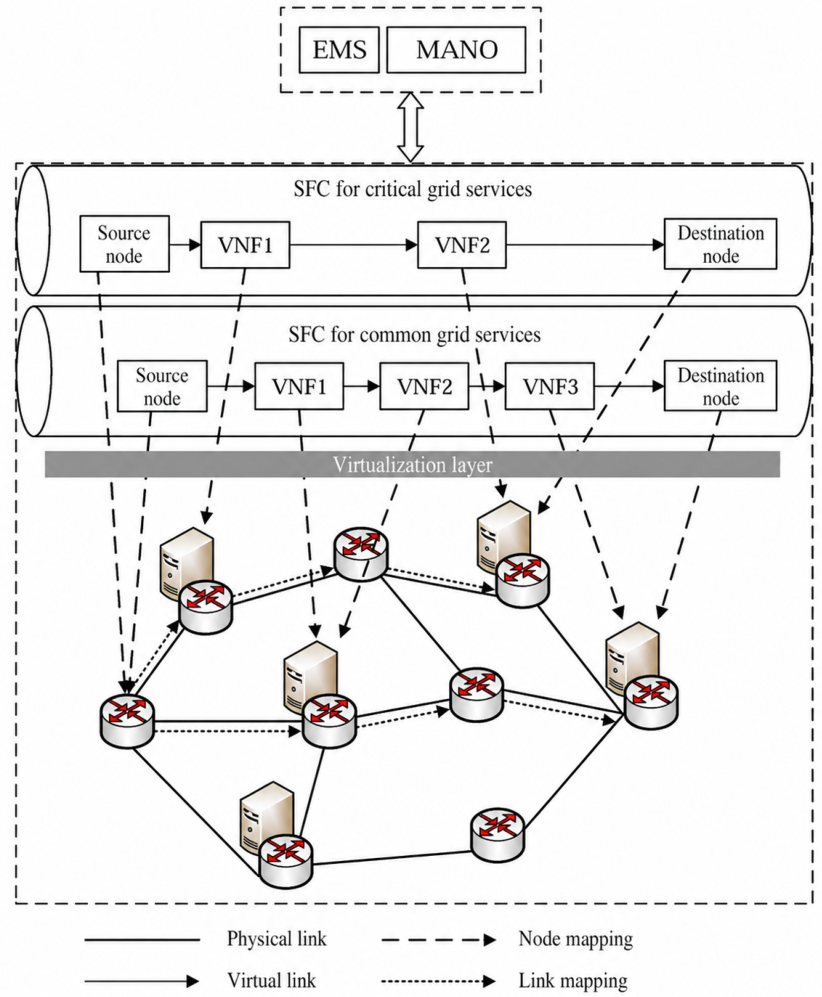
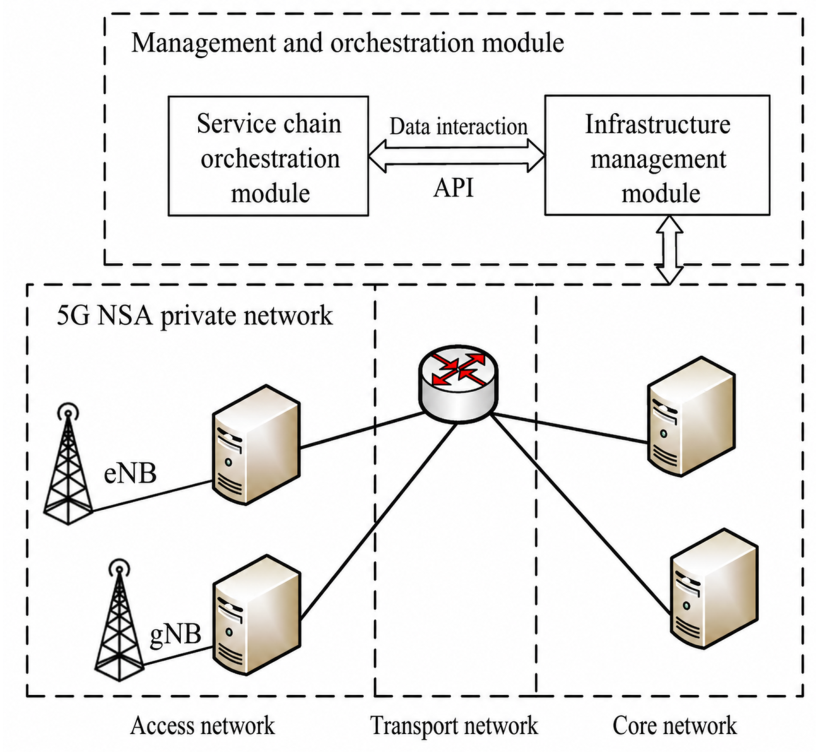
The considered architecture is shown in
Figure 1. In the smart grid private communication network, the management and orchestration (MANO) module is responsible for managing network resources and deploying SFCs on demand for different service requests. Following the service classification in the original model, smart grid services are divided into two categories: critical grid services and common grid services. Critical grid services correspond to services with higher requirements on security and operational reliability, such as production-control-related services. Common grid services correspond to ordinary services such as monitoring, inspection, or management-information services.
To satisfy the physical isolation requirement between different service categories, SFCs serving critical grid services should be physically isolated from SFCs serving common grid services at the server level. Specifically, VNFs belonging to SFCs of different service categories cannot be deployed on the same physical server. The threat considered in this paper is the potential risk caused by co-locating VNFs of different service categories on the same physical server, such as cross-service interference, resource contention, configuration errors, or security risks introduced by shared virtualization environments. Switches, physical links, the MANO module, and the transport infrastructure are assumed to be shared and trusted components in the current model. Therefore, the proposed isolation corresponds to server-level VNF deployment isolation, rather than virtualization-level isolation or end-to-end physical isolation of the entire communication infrastructure. It should be noted that the proposed method does not provide a complete security mechanism for smart grid private networks, and security functions such as encryption, authentication, access control, attack detection, side-channel mitigation, and data-plane traffic isolation are beyond the scope of this paper.
3.2. Substrate Network Model
The substrate network is modeled as an undirected graph
where
V denotes the set of physical nodes and
E denotes the set of physical links. The substrate network contains two types of physical nodes, i.e., servers and switches. Let
denote the set of server nodes and
denote the set of switch nodes. Thus, the physical node set is given by
For a physical node
, its neighboring node set is defined as
For a physical link between two physical nodes
, its bandwidth capacity and propagation delay are denoted by
and
, respectively.
The resource capacity of physical node
is denoted by
. If
, then
, since switch nodes do not provide computing resources for VNF deployment. If
, then
equals the resource capacity of the corresponding server node. Following the original model, servers in the private network are assumed to be homogeneous, and each server has the same resource capacity
C. In addition, a switch and a server located at the same site are assumed to be connected by a local link with unlimited bandwidth and negligible delay [
28].
3.3. SFC Request Model
Let
denote the set of all SFC request indices, and let
be the number of SFC requests. The set of SFC requests serving critical grid services is denoted by
, while the set of SFC requests serving common grid services is denoted by
. Thus,
The
k-th SFC request is represented by a five-tuple
where
and
denote the source node and destination node of request
, respectively.
denotes the bandwidth demand,
denotes the revenue coefficient per unit bandwidth and unit time, and
denotes the logical topology of the SFC request. If
, then
; if
, then
.
The logical topology of request
is represented as
where
is the set of VNFs and
is the set of virtual links. Let
denote the VNF index set of request
. Then, the VNF set and virtual link set of request
are given by
and
Here,
denotes the
v-th VNF of request
. The virtual link
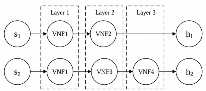
denotes the virtual link between the
v-th VNF and the
-th VNF. In particular,
denotes the virtual link from the source node to the first VNF, and
denotes the virtual link from the last VNF to the destination node.
3.4. VNF and Energy Models
Let
denote the set of VNF types in the network, where
is the number of VNF types. Each VNF in an SFC can be mapped to one VNF type. For any
and
, there exists a VNF type
such that
The processing capability required by the
v-th VNF of request
is defined as [
9]
where
denotes the packet processing time required by the VNF type corresponding to
, and
denotes the packet length of the SFC request.
For the energy model, each server node
has two operating states: active and inactive. Let
be a binary variable indicating the state of server node
i. If server
i is active,
; otherwise,
. When a server is inactive, its energy consumption per unit time is regarded as zero. When a server is active, a linear energy consumption model is adopted, where the energy consumption per unit time is proportional to the used processing capability [
15,
16,
28,
36]. Specifically,
where
is a binary variable. If the
v-th VNF of request
is deployed on physical node
i, then
; otherwise,
.
denotes the energy consumption per unit time when the server is idle, and
denotes the energy consumption per unit time when the server is fully loaded.
It should be noted that this model is used as a tractable first-order approximation of load-dependent server energy consumption. It assumes homogeneous servers and does not explicitly model transient energy overhead caused by container startup or shutdown, the additional overhead introduced by virtualization, or the nonlinear load–power curve of physical servers. In practical hardware platforms, the relationship between server load and power consumption may be nonlinear and device-specific. A more accurate dynamic energy model would require power measurement, curve fitting, and hardware-dependent parameter calibration. In this paper, the linear model is adopted to incorporate an energy-related operating cost into the SFC deployment formulation, while the main focus remains on physical-isolation-aware VNF placement and virtual link mapping.
3.5. Isolation-Aware SFC Deployment Formulation
The considered problem is to deploy SFCs onto the substrate network under limited network resources, while satisfying the bandwidth demands of SFC requests and the physical isolation requirement between critical grid services and common grid services. The objective is to maximize the revenue of network resource usage. It should be clarified that the current optimization explicitly models bandwidth feasibility, server resource constraints, virtual link mapping constraints, and server-level physical isolation, while end-to-end latency and reliability are not imposed as hard QoS constraints. In the proposed algorithm, latency-related information is considered at the deployment level: the server node selection metric includes shortest-path delay and hop count, and virtual links are mapped onto bandwidth-feasible shortest paths. This design helps select shorter paths with lower propagation delay, but it should not be interpreted as a guarantee of service-specific end-to-end delay, delay jitter, or reliability. A hard QoS-constrained formulation would require service-specific delay thresholds, queueing and scheduling models, failure probability models, backup paths, and possibly redundant VNF instances. These extensions are beyond the scope of the current static deployment model and will be considered in future work.
For notational consistency,
is treated as zero for switch nodes, since VNFs can only be deployed on server nodes. First, SFCs serving critical grid services and SFCs serving common grid services cannot place their VNFs on the same server. The physical isolation constraint is expressed as
Second, the total processing capability consumed by all deployed VNFs on a server cannot exceed the server resource capacity
Third, for any physical link
, the total bandwidth consumed by virtual links mapped onto this physical link cannot exceed its bandwidth capacity
where
is a binary variable. If virtual link
l of request
is mapped onto physical link
e, then
; otherwise,
. In addition,
is another representation of
, which indicates whether the virtual link between the
v-th VNF and the
-th VNF of request
is mapped onto the physical link between nodes
i and
. The virtual link
corresponds to the index
, and
corresponds to the index
.
Let
be a binary variable indicating whether SFC request
is successfully deployed. If request
is successfully deployed, then
; otherwise,
. The relationship between
and the deployment status of all VNFs in request
is expressed as
The flow conservation constraints are given in (
17)–(
21). Constraint (
17) ensures the flow conservation of the physical path mapped by the virtual link between two adjacent VNFs. Constraint (
18) ensures the flow conservation at the source node. Constraint (
19) ensures the flow conservation of intermediate physical nodes for the virtual link from the source node to the first VNF. Constraint (
20) ensures the flow conservation at the destination node. Constraint (
21) ensures the flow conservation of intermediate physical nodes for the virtual link from the last VNF to the destination node.
For the virtual link between the
v-th VNF and the
-th VNF, the flow conservation constraint is
For the virtual link from the source node to the first VNF, the source-node constraint is
and the corresponding flow conservation constraint for other nodes is
For the virtual link from the last VNF to the destination node, the destination-node constraint is
and the corresponding flow conservation constraint for other nodes is
The virtual link mapping constraints are given in (
22)–(
27). Constraint (
22) ensures that a virtual link is not simultaneously mapped onto both directions of the same physical link. Constraints (
23) and (
24) ensure that the physical path mapped by each virtual link contains no loop. Constraints (
25)–(
27) ensure that if two adjacent logical elements of an SFC are located on the same physical node, then no physical link is mapped for the corresponding virtual link.
A virtual link cannot be simultaneously mapped onto both directions of the same physical link
For any virtual link, at most one outgoing physical link can be selected from each physical node
Similarly, at most one incoming physical link can be selected for each physical node
If the source node and the first VNF of request
are located on the same physical node, the virtual link
should not be mapped onto any physical link
If the last VNF and the destination node of request
are located on the same physical node, the virtual link
should not be mapped onto any physical link
If the
v-th VNF and the
-th VNF of request
are deployed on the same physical node, the virtual link
should not be mapped onto any physical link
The operating state of a server is related to whether a VNF is deployed on it. Therefore,
Considering that private network users are concerned with the economic benefit generated by network services, the objective is formulated as maximizing the revenue of network resource usage
where
denotes the electricity price per unit energy. The energy-related term in the objective function is introduced to represent the operating cost associated with active servers during SFC deployment. It provides a simplified energy-cost consideration rather than a comprehensive model for evaluating green computing performance, since hardware-level power dynamics and nonlinear server load-power characteristics are not explicitly incorporated in the current formulation.
3.6. Linearization of Nonlinear Constraints
The optimization model above is an INLP model because it contains nonlinear constraints, including the physical isolation constraint, the SFC deployment indicator constraint, and the logical link mapping constraints. Since linear programming problems have more mature solution methods than general nonlinear programming problems, these nonlinear constraints are transformed into linear constraints, so that the model can be converted into an ILP model.
First, the physical isolation constraint in (
13) is nonlinear. Since
is a binary variable for any
,
, and
, (
13) can be equivalently written as
For binary variables, suppose that
Then, the following linear relationships hold
According to (
32), when
, (
30) can be transformed into
Second, the nonlinear SFC deployment indicator constraint in (
16) can be linearized. Since
and
, (
16) can be replaced by
and
Third, the logical constraints in (
25)–(
27) are also nonlinear. They can be linearized by introducing auxiliary binary variables and applying the big-
M method.
For binary variables
m and
n, suppose that
Then, the same relationships as (
32) hold. If
then the following linear relationships hold
Moreover, for
and
, if
implies
, this logical implication can be linearized by the big-
M method as
where
M is a sufficiently large constant.
Taking (
25) as an example, define
The auxiliary variable
is constrained by
For notational compactness, define
Then, (
25) can be linearized as
Similarly, (
26) and (
27) can be linearized by the same method.
After replacing the nonlinear constraints (
13), (
16), and (
25)–(
27) with their corresponding linear forms, the original INLP model is transformed into an ILP model. Therefore, the transformed model can be solved by an optimizer such as CPLEX through the branch-and-bound method.
The generated ILP model still has high computational complexity. Its size increases with the number of SFC requests, VNFs, candidate server nodes, virtual links, and physical links. In particular, the linearized physical isolation constraint introduces pairwise mutual-exclusion constraints between VNFs of different service categories on each physical server, and the logical mapping constraints introduce auxiliary variables and big-M constraints. These additional variables and constraints enlarge the branch-and-bound search space and may increase computation time and memory consumption. Therefore, the ILP model is mainly used as an exact benchmark for small-scale cases, while a heuristic algorithm is needed for larger-scale deployment scenarios.




 and
and