Article

Design and Field Implementation of a Communication System for Inspection Robots in Caged Broiler Houses


1
Key Laboratory of Smart Breeding (Co-Construction by Ministry and Province), Ministry of Agriculture and Rural Affairs, Tianjin 300384, China
2
College of Computer and Information Engineering, Tianjin Agricultural University, Tianjin 300384, China
*
Author to whom correspondence should be addressed.
These authors contributed equally to this work.
Electronics 2026, 15(11), 2406; https://doi.org/10.3390/electronics15112406
Submission received: 16 April 2026 / Revised: 24 May 2026 / Accepted: 28 May 2026 / Published: 1 June 2026

Abstract

This study proposes and implements a hierarchical communication system for inspection robots operating in practical caged broiler houses, where confined aisles, multi-tier cages, dust, humidity, and fluctuating wireless coverage impose challenges on stable remote inspection. The system uses Jetson Orin NX as the robot-side main controller, with industrial Ethernet and RS-485 supporting onboard device access, and Robot Operating System 2 (ROS 2) used for device coordination, data processing, and task scheduling. At the robot-cloud interaction level, Message Queuing Telemetry Transport (MQTT) is used for task delivery, status feedback, alarm reporting, and environmental data upload, while a real-time preview channel and sampled key-frame transmission support video monitoring and inspection-process retention. The proposed architecture organizes the control link and data link within an end-to-end closed loop and incorporates acknowledgment, buffering, reconnection, and abnormal-state handling mechanisms to improve communication availability under weak-network field conditions. Long-term field tests in a commercial caged broiler house demonstrated that the system could maintain reliable remote command execution, continuous status feedback, stable visual data transmission, and stable environmental telemetry upload during routine inspection tasks. The results indicate that the proposed communication architecture can provide practical support for remote inspection robots in smart poultry farming scenarios.

1. Introduction

With the development of large-scale and intensive broiler production, poultry house management is gradually shifting from experience-driven practice to a digital operating mode characterized by continuous sensing, remote decision-making, and process traceability [1]. In this context, information related to temperature and humidity, harmful gases, illumination, behavioral status, and welfare risks must be acquired and organized in a more timely and fine-grained manner to support precision environmental regulation, production management, and animal welfare assurance [2,3]. Compared with fixed monitoring devices, inspection robots with mobile observation capability can collect near-field, multi-point, and task-related data across the spatial extent of the poultry house and have therefore gradually been regarded as important on-site execution units in smart poultry farming [4,5].
Existing poultry monitoring systems are still mainly based on fixed nodes, localized sensing, and static-point observation. Although such approaches are valuable for recording environmental trends, they often struggle to simultaneously provide spatial coverage, near-field observation, and task-oriented process linkage in large-scale poultry houses [6,7]. Research on mobile robots for poultry applications has already demonstrated the feasibility of platform-based inspection. For example, PoultryBot verified the operational and auxiliary inspection potential of an autonomous mobile platform in poultry houses, whereas RobôFrango further demonstrated the application prospects of mobile robots for near-field environmental monitoring in broiler houses [8,9]. However, most existing studies have focused on navigation, target detection, visual localization, or other single-function implementations. Progress has been reported in areas such as road-feature-based navigation in caged chicken houses, machine-vision-based navigation, and abnormal-individual inspection [10,11,12]. Therefore, although previous studies have demonstrated the feasibility of introducing mobile robots into poultry houses, less attention has been paid to how these robots can maintain coordinated operation, remote interaction, and recoverable data transmission under real farming conditions [13]. As shown in Table 1, representative studies have mainly focused on platform feasibility, environmental monitoring, navigation, or inspection functions, whereas robot-side coordination, robot-cloud communication, and weak-network recovery have rarely been treated as the central objects of system design and validation.
Compared with floor-rearing poultry houses or general indoor mobile scenarios, large-scale caged broiler houses are characterized by narrow aisles, multi-tier cage structures, repetitive layouts, and frequent occlusion. These features not only increase the difficulty of stable robot traversal and multi-view observation but also make task execution more dependent on continuous state feedback and cross-module coordination [14,15]. More importantly, under long-term real-house operation, dust, high humidity, equipment disturbance, and fluctuating wireless coverage can further degrade sensing data quality, device stability, and communication continuity [16]. As a result, the problem is no longer merely whether a robot can move and perceive, but should instead be understood as a system-level communication problem involving heterogeneous device integration, hybrid service-flow organization, and recoverable operation under weak-network conditions [17,18,19]. Beyond poultry house robots, similar communication and coordination requirements have also been reported in agricultural robots, industrial mobile robots, and wheeled mobile manipulators operating in complex environments [20]. These systems commonly require continuous state feedback, coordinated module interaction, and reliable message exchange to maintain task execution under non-ideal operating conditions [21,22]. Studies on IoRT-based middleware and distributed ROS 2 communication have further shown that middleware selection and edge-to-edge or edge-to-cloud transmission paths can affect latency, throughput, resource consumption, and system availability under different network conditions [23,24,25]. Nevertheless, these studies have mainly been conducted in general robotic, industrial, or distributed computing scenarios, whereas communication system design and long-term field validation for caged broiler inspection robots remain limited.
Motivated by the above considerations, this study proposes a hierarchical communication architecture for inspection in caged broiler houses, in which internal robot communication and robot-cloud communication are jointly organized within a unified end-to-end closed loop. On the robot side, ROS 2 is used to coordinate the chassis, lifting mechanism, environmental sensing unit, and visual unit, while Industrial Ethernet and RS-485 are employed to support heterogeneous device access. At the robot-cloud interaction level, a remote communication mechanism is established for task delivery, status feedback, and inspection data upload, together with link reconnection, buffered retransmission, and abnormal-state handling strategies to improve operational availability under weak-network and complex field conditions. The focus of this work is not on improving a single navigation or perception algorithm in isolation, but on providing a communication-oriented system implementation and field-validation framework for caged broiler inspection robots, thereby offering an engineering basis for reliable remote command delivery, continuous status feedback, and stable transmission of multi-source inspection data.
The novelty of this study lies not in the individual adoption of ROS2, MQTT, RS-485, or a hierarchical structure, but in their field-oriented integration into a communication-centered architecture for caged broiler inspection robots. Compared with previous poultry house robotic studies that mainly verified mobile inspection, navigation, environmental sensing, or abnormal-target detection functions, this study defines and validates both the control and data communication loops under commercial caged-house conditions. In particular, it emphasizes multi-device access, robot-cloud message mapping, acknowledgment, buffering, reconnection, and long-term field operation as core components of the communication system.
The main contributions of this study are summarized as follows:
  • A robot-side communication structure is developed by combining industrial Ethernet, RS-485, and ROS2, supporting coordinated access to onboard sensing, motion, and execution units.
  • An MQTT-based robot-cloud communication mechanism is implemented for task delivery, status feedback, alarm reporting, environmental data upload, and visual key-frame transmission.
  • The control link and data link are organized separately, with acknowledgment, buffering, reconnection, and abnormal-state handling mechanisms used to improve communication availability under weak-network field conditions.
  • The system is evaluated through long-term field implementation in a commercial caged broiler house, demonstrating its applicability to routine remote inspection tasks.

2. Materials and Methods

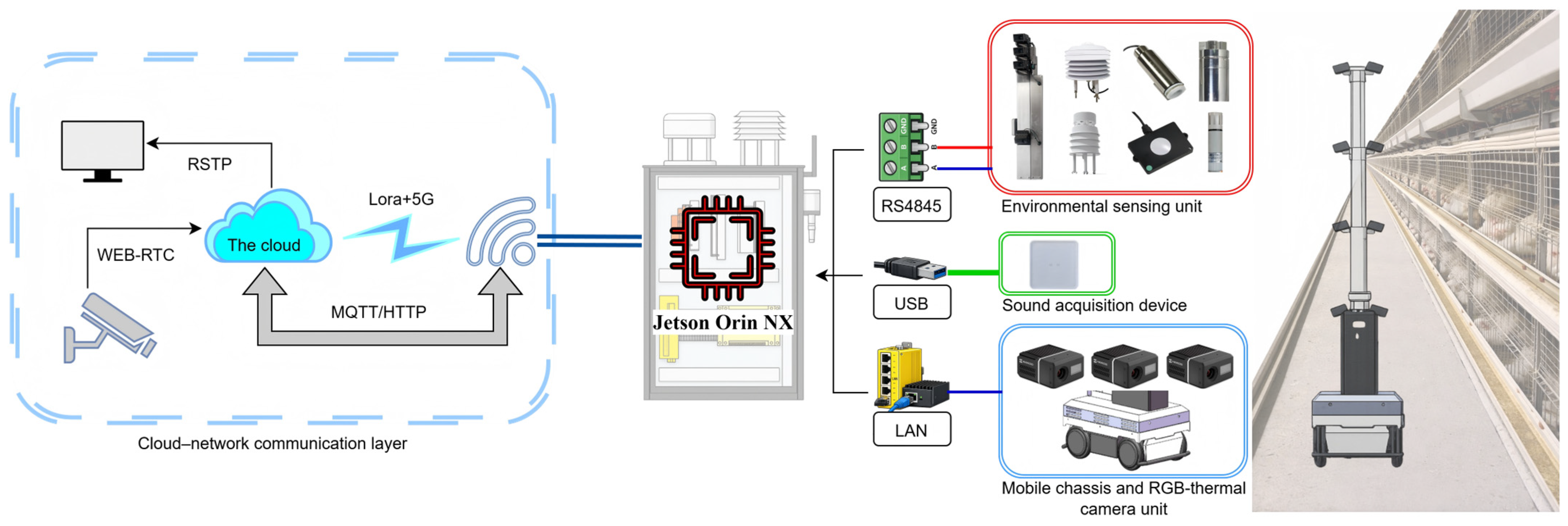
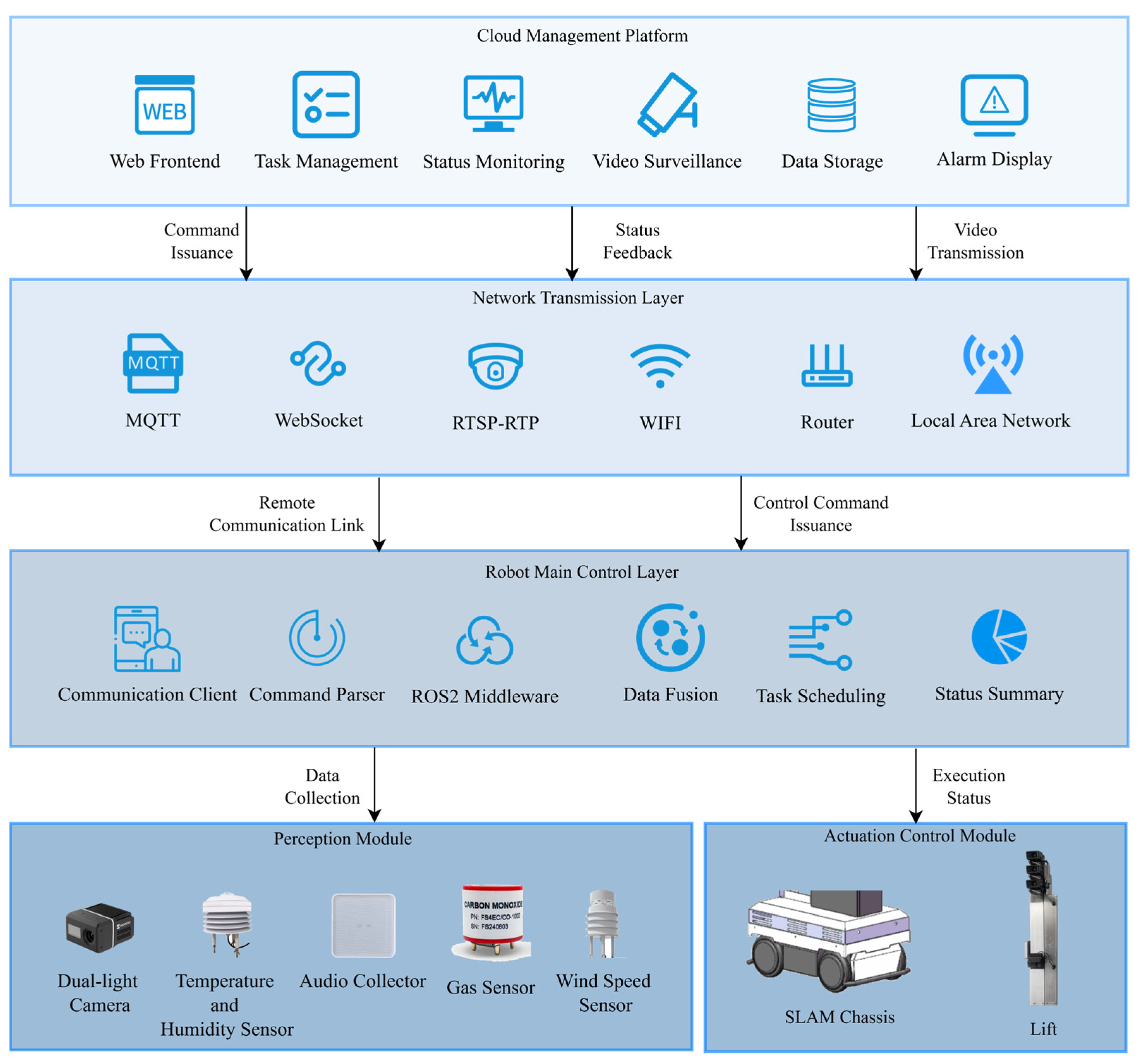
To cope with the practical constraints of caged broiler houses, such as narrow aisles, multi-layer cage arrangements, high humidity, heavy dust, and unstable wireless connectivity, the inspection robot system was formulated as a mobile communication and coordination system composed of the robot side, the wireless network, and the cloud platform. As shown in Figure 1, the system is characterized by three aspects, namely system composition, closed-loop workflow, and hierarchical organization [26,27]. In this architecture, the robot side undertakes on-site sensing, device control, and local task execution, while the cloud platform is responsible for remote task organization, operational status collection, and inspection-process management. Bidirectional communication between the two ends is established through the wireless network, thereby forming a remote inspection closed loop for practical poultry house deployment.
From a functional perspective, system communication can be divided into two categories: the control link and the data link. The former is used for remote task delivery, robot-side execution, and status feedback, whereas the latter supports the acquisition, transmission, and cloud-side retention of visual and environmental information generated during inspection. On this basis, the communication architecture is further organized into two interacting levels, namely robot-cloud external communication and intra-robot communication. The former is responsible for cross-end task interaction and upstream data transmission, while the latter supports coordination among heterogeneous devices and functional modules within the robot itself. The following sections describe the roles of the robot side and the cloud side, the end-to-end closed-loop workflow, and the corresponding communication mechanisms.
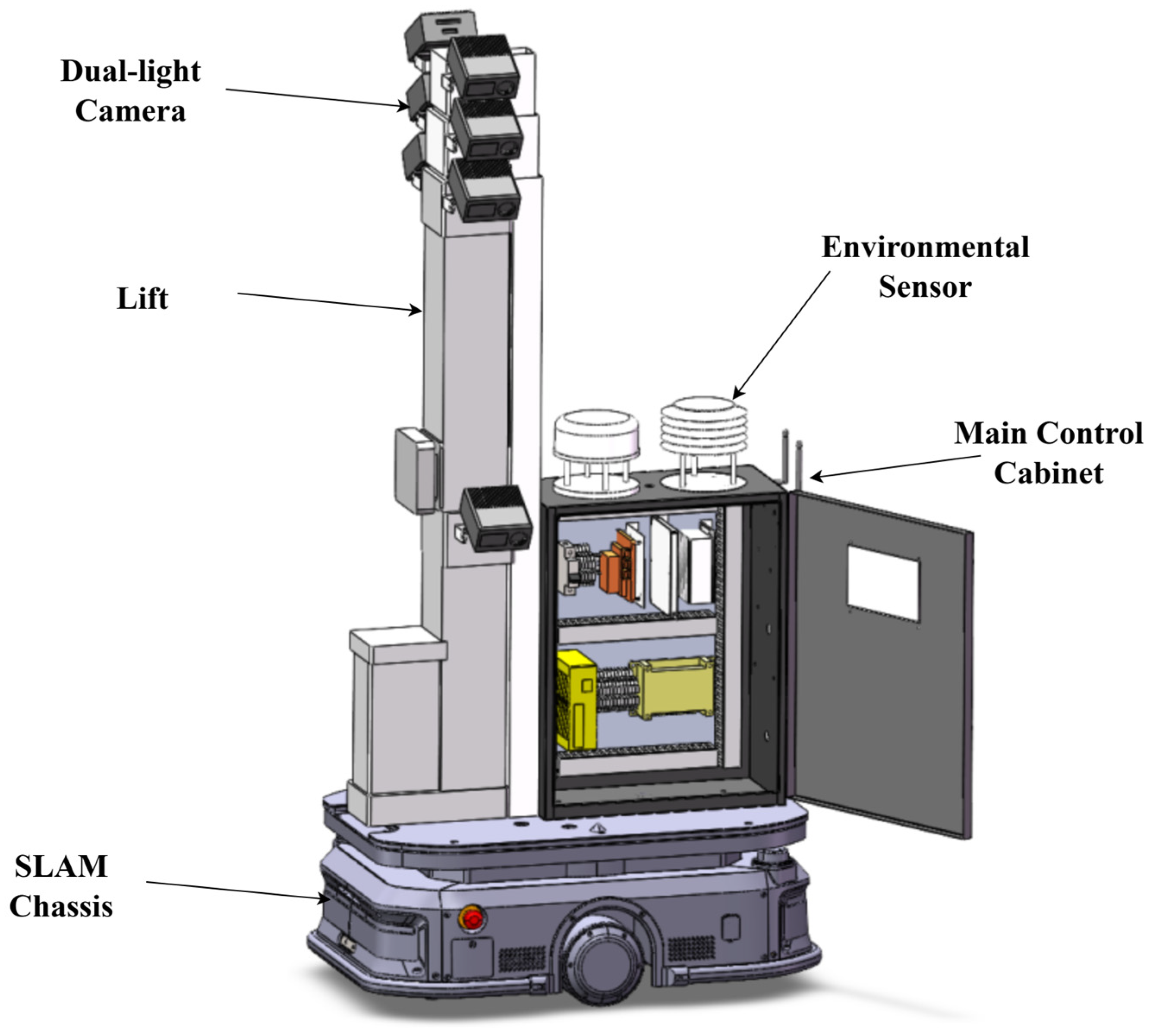
The robot side serves as the on-site execution entity of the system, undertaking mobile inspection, environmental sensing, visual acquisition, and local task coordination. Considering the distinctive spatial configuration and operating conditions of caged broiler houses, the robot platform was designed in a modular manner and consists of a mobile chassis, a lifting mechanism, a main control cabinet, a vision system, and an environmental sensing unit. This configuration enables stable movement within narrow aisles, observation of multi-tier cages, and integration of heterogeneous sensing data, as shown in Figure 2.

2.1. Robot-Side Design

SLAM chassis: The mobile chassis provides the locomotion foundation for inspection tasks. It enables autonomous navigation, path tracking, and point-to-point docking within the poultry house aisles, while also providing the mechanical support and mobility required for the entire platform.
Lifting mechanism: The lifting mechanism is mounted above the chassis and is used to adjust the observation height to accommodate inspection requirements under multi-layer cage arrangements. By allowing the sensing units to operate at different elevations, it improves both inspection coverage and observation flexibility.
Main control cabinet: The main control cabinet functions as the control and management center of the robot side. It integrates computing resources, power supply, device access, and local coordination functions, thereby providing a unified operational platform for all robot subsystems and supporting task execution as well as data aggregation during inspection.
Vision system: The vision system consists of eight network cameras deployed at different heights and orientations on the lifting structure, enabling multi-view coverage of the aisle and multi-tier cage areas. This module is primarily responsible for visual data acquisition during inspection and provides the basis for remote monitoring, process traceability, and subsequent image analysis.
Environmental sensing unit: The environmental sensing unit is used to collect key environmental parameters, including temperature, humidity, air velocity, illuminance, and gas concentration, as listed in Table 2. Combined with robot movement, this module generates spatially associated environmental observations, thereby providing a data basis for evaluating environmental conditions inside the poultry house.

2.2. Cloud-Side Design

The cloud platform serves as the remote management and information aggregation center of the system, mainly supporting task organization, operational monitoring, data retention, and result presentation. In the inspection scenario of caged broiler houses, the cloud side does not directly participate in low-level device control; instead, it acts as the upper-level support layer connecting user operations with on-site robot execution, thereby providing a unified entry point for task initiation, execution tracking, and process management [28,29].
From a functional perspective, the cloud platform mainly supports three categories of services. The first is task management, which is responsible for inspection-task configuration, initiation, and process recording. The second is status reception, which is used to collect task states, device states, and abnormal events generated during robot operation. The third is data retention, which receives and manages the visual information, environmental data, and related process records uploaded from the robot side.

2.3. End-to-End Closed-Loop Design

Once the functional roles of the robot side and the cloud side are defined, the system can be further described from two complementary perspectives, namely the control link and the data link. In this study, system communication is not treated merely as a message transmission process, but rather as a closed-loop infrastructure that supports task execution, status feedback, and data retention.

2.3.1. Control Link Workflow

The control link describes the closed-loop process by which remote inspection tasks are delivered from the cloud side to the robot side and are ultimately translated into executable actions. It mainly supports remote scheduling and task execution, with emphasis on whether tasks can be correctly received, stably executed, and accompanied by state feedback. The basic workflow is as follows: the cloud platform generates task requests according to the inspection plan; the robot side receives the requests and performs local scheduling based on the current operating state; the received tasks are then converted into executable actions such as chassis movement, lifting adjustment, or other inspection-related operations. During execution, the robot continuously generates task states and operational feedback and returns key results to the cloud side for remote monitoring and process tracking, as shown in Figure 3.
Unlike communication descriptions that regard message arrival alone as task completion, this study defines the endpoint of the control loop as the actual realization of robot actions. In other words, a remote task is considered completed only when it is not only received by the robot side but also converted into executable behavior and followed by corresponding state feedback. Therefore, the control link focuses not simply on command transmission itself, but on the executability and traceability of remote tasks under real on-site conditions.

2.3.2. Data-Link Workflow

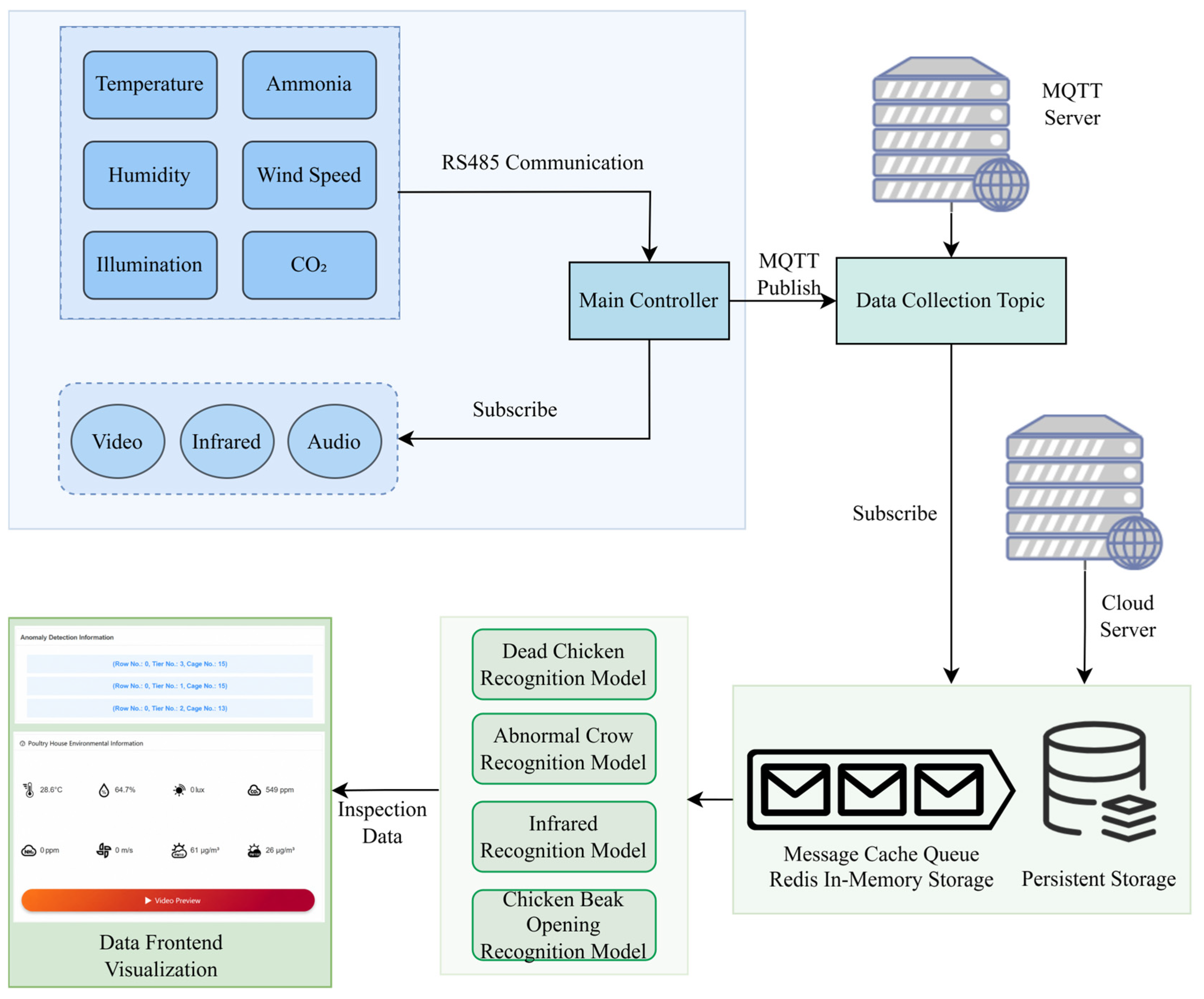
The data link describes the closed-loop process by which visual information and environmental data generated during inspection are produced on the robot side, uploaded, and ultimately made available on the cloud side for storage, visualization, and analysis. It mainly supports information acquisition and retention during the inspection process, with emphasis on whether sensing data can be continuously uploaded and transformed into usable cloud-side results. The basic workflow is as follows: during inspection, the robot continuously acquires visual information and environmental parameters, organizes the corresponding data, and uploads them to the cloud platform. After reception, storage, and presentation on the cloud side, the inspection data become available for querying, playback, and further analysis, as shown in Figure 4.
Different from the control link, the data link is centered not on action triggering but on information retention and result availability. In this study, the endpoint of the data loop is defined as the point at which cloud-side data become available, rather than the point at which data acquisition is completed on the robot side. In other words, the data link is regarded as truly closed only when the images and environmental data generated during inspection are stably aggregated and transformed into usable results on the cloud platform.

3. Communication System Design

This section presents the information organization and interaction mechanisms both within the robot and between the robot and the cloud platform. The communication design focuses on heterogeneous device integration, coordinated task scheduling, multi-source data transmission, and communication availability under unstable wireless conditions. The robot’s internal communication architecture, robot-side functional modules, and cloud communication mechanisms are described in the following subsections. Before presenting the detailed modules, the main technological choices used in the communication architecture are summarized in Table 3. The comparison focuses on their roles in the proposed system and the practical reasons for selecting them under caged broiler-house conditions.
These choices were not intended to replace navigation or perception algorithms, but to provide a communication structure that can organize heterogeneous devices, remote commands, status feedback, and multi-source data transmission under field deployment conditions.

3.1. Overall Internal Communication Architecture

The internal communication architecture of the robot supports the coordinated operation of sensing, control, status feedback, and local task processing, and thus forms the basis for closed-loop execution on the robot side. Because the inspection robot integrates vision devices, environmental sensing units, motion actuators, and local interaction components, a layered architecture was adopted to unify heterogeneous device access, data aggregation, and task scheduling.
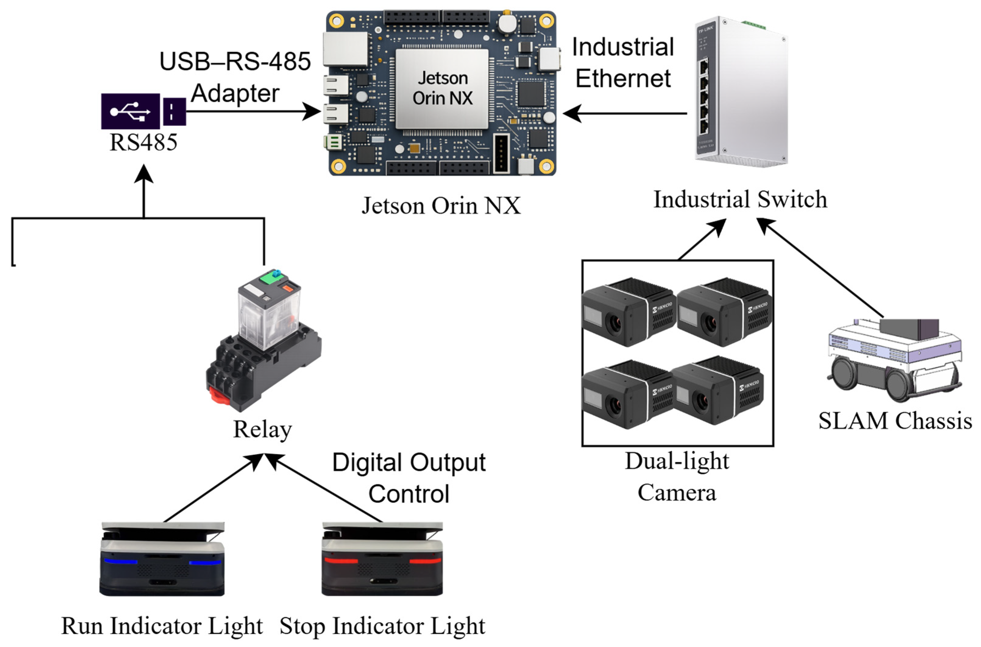
At the hardware level, the internal communication system is composed of Ethernet-based access and fieldbus-based access. Figure 5 focuses on the hardware communication topology of the robot side, showing how heterogeneous devices are physically connected to the main controller through Ethernet-based and RS-485-based access paths. The vision system and the chassis, which involve higher-bandwidth or stronger real-time interaction requirements, are organized on the network side, whereas environmental sensing, lifting control, and peripheral devices are organized on the field-device side. Therefore, Figure 5 describes the device-access layer of the internal communication system, rather than the software functional organization.
Above this hardware access layer, the internal communication functions are further organized through ROS 2-based messaging and task-coordination mechanisms, as described in Section 3.2.

3.2. ROS 2 Package Design

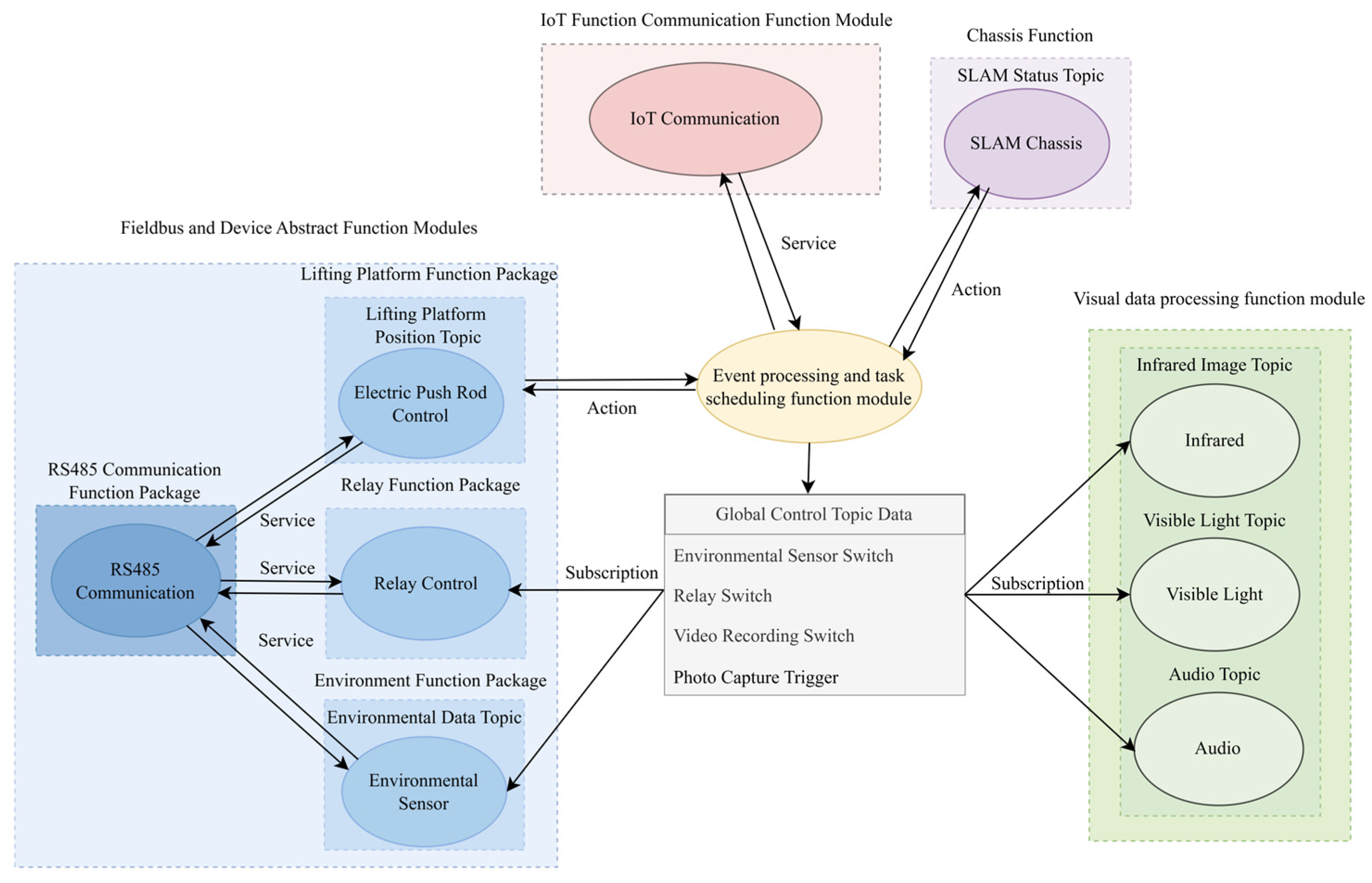
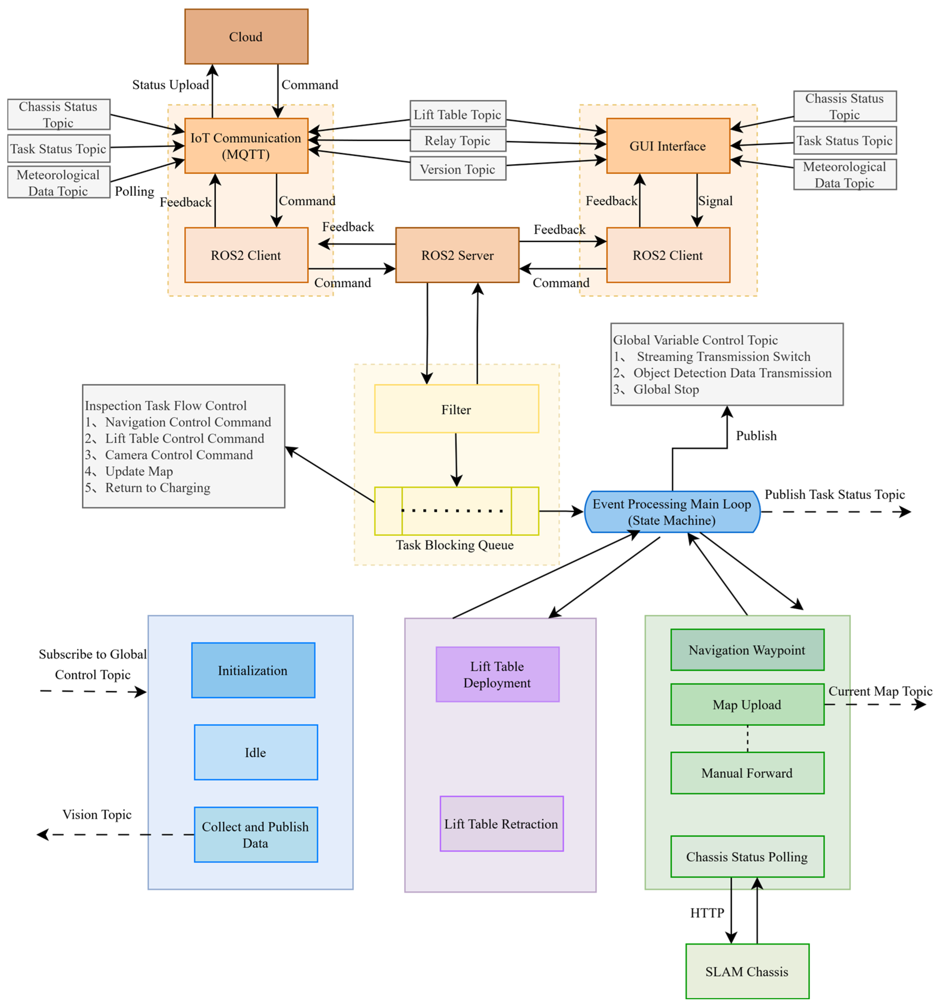
Based on the hardware communication topology shown in Figure 5, the robot-side software was further decomposed into ROS 2-based functional modules. Unlike Figure 5, which describes the physical and protocol-level access of heterogeneous devices, Figure 6 focuses on the software organization above the hardware access layer. It shows how cloud-command access, field-device communication, visual data processing, and coordinated task control are encapsulated into functional modules and coordinated through the ROS 2 communication mechanism [18,19,30].
According to their functional responsibilities, the ROS 2 system on the robot side mainly consists of four categories of modules: the IoT communication module, the fieldbus and device abstraction module, the visual data processing module, and the event-processing and task-scheduling module, as shown in Figure 6. These modules form the software backbone of the robot side and provide the basis for implementing the end-to-end control link and data link.

3.2.1. IoT Communication Module

The IoT communication module is used to establish the message channel between the robot side and the cloud platform. It is responsible for external network access, MQTT session maintenance, and message mapping between cloud-side messages and internal ROS 2 messages. This module runs on the robot side and supports multiple Wi-Fi configurations, link-status monitoring, and automatic reconnection, thereby maintaining continuous connectivity under fluctuating wireless conditions. In the field deployment, the poultry house was covered by a multi-access-point Wi-Fi network along the approximately 100 m inspection aisle. The access points were connected to the farm gateway through wired backhaul, and the robot accessed the external cloud platform through the house Wi-Fi network during inspection. The MQTT broker and the cloud backend were deployed on the same cloud-side server, so that command distribution, acknowledgment reception, status storage, and data visualization could be handled within the same service environment. The robot maintained only one active MQTT client session during operation, while different service flows were separated by predefined topic namespaces.
In terms of communication organization, the module adopts an MQTT publish/subscribe mechanism. According to service type, the Topics are divided into three categories: control Topics, status Topics, and data Topics. Control Topics are used to receive commands such as task start, task stop, waypoint inspection, and emergency stop. Status Topics are used to report robot operating states, device states, and abnormal events. Data Topics are used to upload environmental parameters and visual key frames. The robot receives control messages from the cloud backend by subscribing to control Topics and outputs operational information and sensing results by publishing status and data Topics. To accommodate different reliability requirements across services, control messages are prioritized with transmission strategies emphasizing reliable delivery, whereas periodic status messages are designed to balance communication load and transmission efficiency.
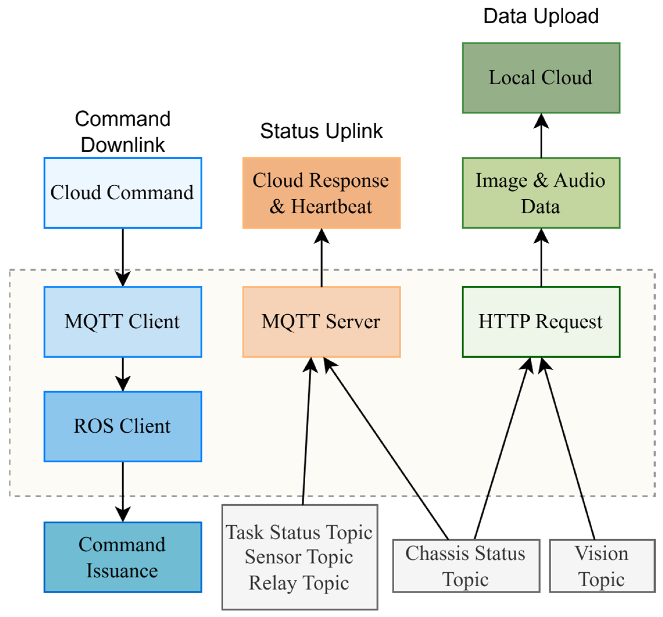
Functionally, this module consists of two parts, namely uplink message publication and downlink command reception, as shown in Figure 7. On the uplink side, the module subscribes to key internal Topics on the robot, such as visual key frames, structured detection results, environmental data, and operational states, and encapsulates the original ROS messages into structured messages that can be processed by the cloud platform. Uplink messages typically include fields such as timestamps, robot pose, status identifiers, message type, and payload content. On the downlink side, the module receives cloud-issued tasks and control commands and, after field parsing, format validation, and parameter checking, converts them into ROS service requests or task-triggering signals, which are then forwarded to the event-processing and task-scheduling module. Downlink commands typically include fields such as command type, task identifier, parameter content, priority, and timestamp.
To cope with weak-network conditions, a link-recovery mechanism was incorporated into this module. When the Wi-Fi connection is interrupted or the MQTT session is abnormally disconnected, the system can automatically re-establish the connection and restore subscriptions to critical Topics. For status messages that cannot be transmitted in time during short-term fluctuations, the module temporarily stores them in a buffer queue and resumes uploading after the link is restored. For critical control messages, acknowledgment and retransmission mechanisms are used to reduce the risk of message loss. Through this design, a relatively clear interface boundary is established between the internal ROS 2 messaging on the robot side and the MQTT-based cloud communication.

3.2.2. Fieldbus and Device Abstraction Module

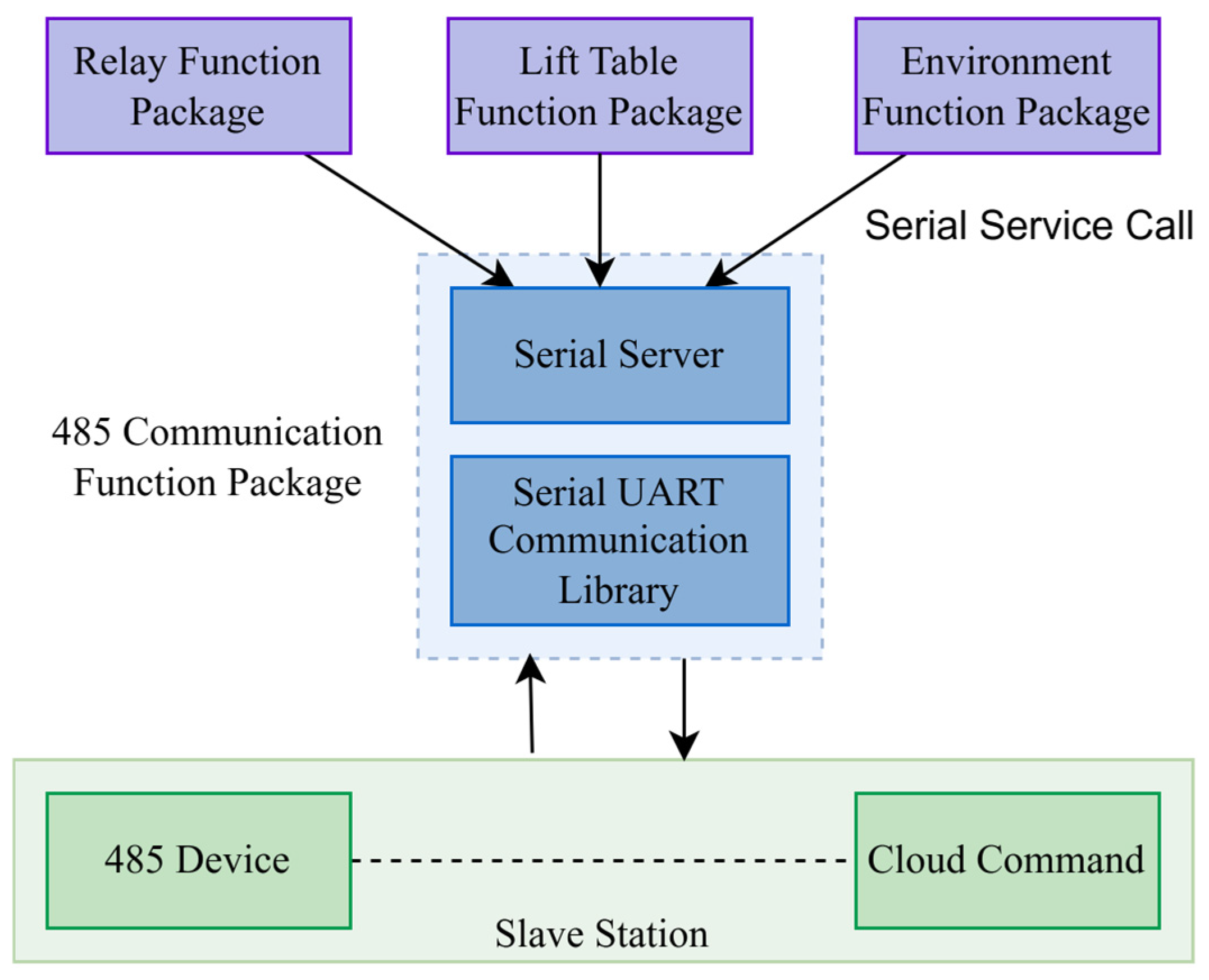
The fieldbus and device abstraction module is designed to provide unified management of RS-485 peripherals on the robot side, including the environmental sensing module, relay-control module, and lifting actuator. Located at the device-access layer, this module is responsible for fieldbus communication management, abstraction of device states, and unification of control interfaces, thereby providing higher-level ROS 2 modules with a consistent method for device access.
At the implementation level, the module adopts RS-485 as the physical bus and uses Modbus RTU for register-level data exchange. Considering the presence of dust, high humidity, and electromagnetic interference in poultry house environments, a single-master communication mode was adopted, in which an independent node centrally manages the RS-485 link and performs frame transmission, response reception, polling scheduling, and timeout handling [31]. This design avoids bus contention and access conflicts that could arise from direct multi-node access.
In terms of interface organization, although different peripherals perform state acquisition and command execution through register read/write operations, the register addresses, access rules, and protocol details are encapsulated within the driver layer, as summarized in Table 4. Higher-level modules do not directly manipulate Modbus RTU registers; instead, they access device capabilities through unified ROS 2 interfaces, such as reading environmental parameters, setting relay states, controlling lifting positions, and querying device status. In this way, the low-level communication implementation is decoupled from upper-level task logic.
The data handled by this module can be broadly classified into two categories, namely device-state data and device-control data, as shown in Figure 8. The former includes environmental parameters such as temperature, humidity, and gas concentration, as well as relay states, lifting positions, and device fault codes. The latter includes start/stop commands, relay-control commands, target lifting positions, and parameter configurations. After frame parsing and data conversion, the module either publishes device states as structured ROS 2 messages or maps control requests into device-level execution operations, which can then be invoked by the task-scheduling module and the IoT communication module.
In the event of device-response timeout, validation failure, or repeated polling anomalies, the module performs state detection and error reporting. Non-critical acquisition tasks are allowed a limited number of retries within the polling cycle, whereas execution-oriented devices rely on state interlocks and error reporting to prevent unsafe or unintended operations. Overall, the role of this module is to provide the robot side with a stable and consistent foundation for device access, rather than to undertake upper-level task decision-making.

3.2.3. Visual Data Processing Module

The visual data processing module is responsible for multi-camera video stream access, decoding, frame sampling, and image message publication, and serves as the visual processing unit within the internal data plane of the robot. Its main task is to convert continuous video streams into structured image messages that can be shared within the ROS 2 framework, thereby supporting subsequent detection, event triggering, and cloud upload.
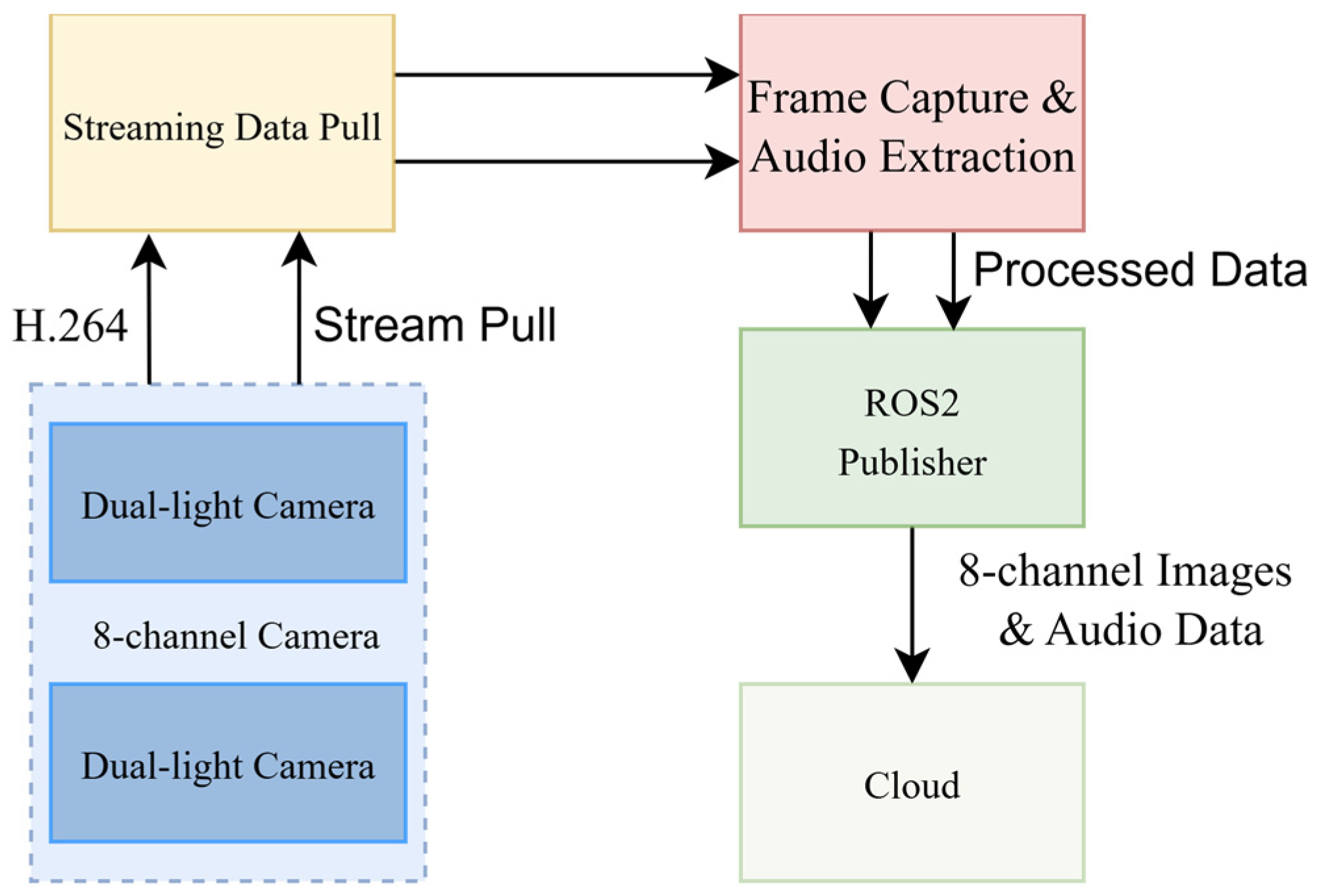
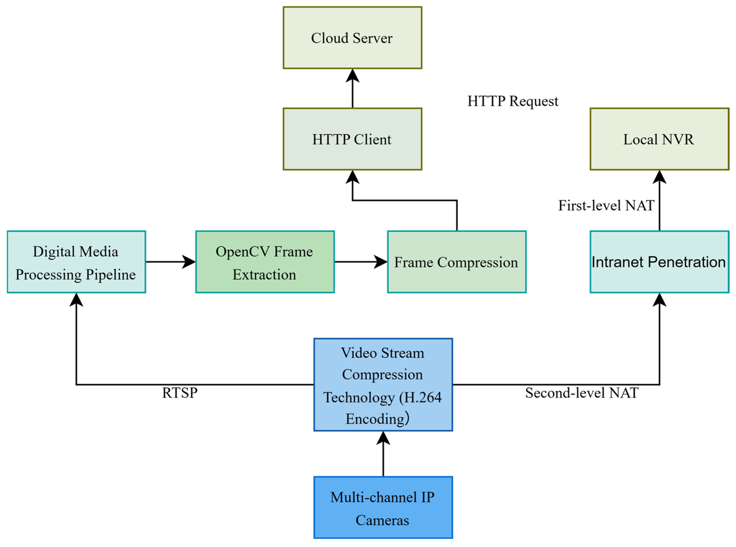
The system acquires video streams from eight network cameras through the internal Ethernet, with video encoded in H.264 and transmitted at a resolution of 720p. Considering the computational resources available on the robot side and the limitations of communication bandwidth, a periodic key-frame sampling strategy was adopted, in which image frames are extracted at 0.5 s intervals and published to the internal communication bus, as shown in Figure 9. Compared with continuous full-frame processing, this approach reduces the resource consumption associated with sustained decoding and data distribution.
In the processing workflow, the module first receives and decodes the video streams, converting the original encoded streams into image data. Key frames are then sampled at the predefined interval and enriched with metadata such as timestamps and camera identifiers. Finally, the results are published as image messages in a unified format for subscription by other modules. Through this process, the original video streams are transformed into visual data units with explicit temporal semantics and source identification.
The image messages generated by this module mainly serve two upper-level processes. One is the event-processing and task-scheduling module, which subscribes to visual data or subsequent detection results to trigger inspection events, assist status judgment, or adjust the control workflow. The other is the IoT communication module, which subscribes to key frames or structured image results and uploads them to the cloud after encapsulation together with pose and task-state information. In this way, the visual data processing module provides both visual data standardization and internal data sharing.
From an implementation perspective, the module does not transmit complete continuous video through the internal communication chain; instead, it adopts a “stream access-decoding-sampled publication” strategy to balance real-time performance, computational load, and bandwidth consumption. This design is better suited to inspection scenarios in which data usage is centered on task events rather than on full continuous video processing.

3.2.4. Event-Processing and Task-Scheduling Module

The event-processing and task-scheduling module organizes the operating workflow of the robot-side control plane and acts as the core scheduling hub connecting upper-level task requests with lower-level execution units. This module does not directly perform sensing, low-level device driving, or cloud communication. Instead, it is responsible for the unified intake, state judgment, sequential organization, and execution coordination of task requests and local events entering the control plane, thereby ensuring that robot actions during inspection remain consistent, controllable, and traceable.
With respect to input sources, the module receives two categories of information. The first consists of external task requests, including inspection commands issued from the cloud and control signals generated by the local interface. The second consists of internal robot states and event information, including operational feedback, abnormal alarms, and condition changes originating from the visual pipeline, device-state pipeline, and safety-detection pipeline. By processing external requests and internal events within the same scheduling framework, the system avoids distributing control logic across multiple nodes and thereby reduces the risk of action conflicts caused by multi-entry concurrent control.
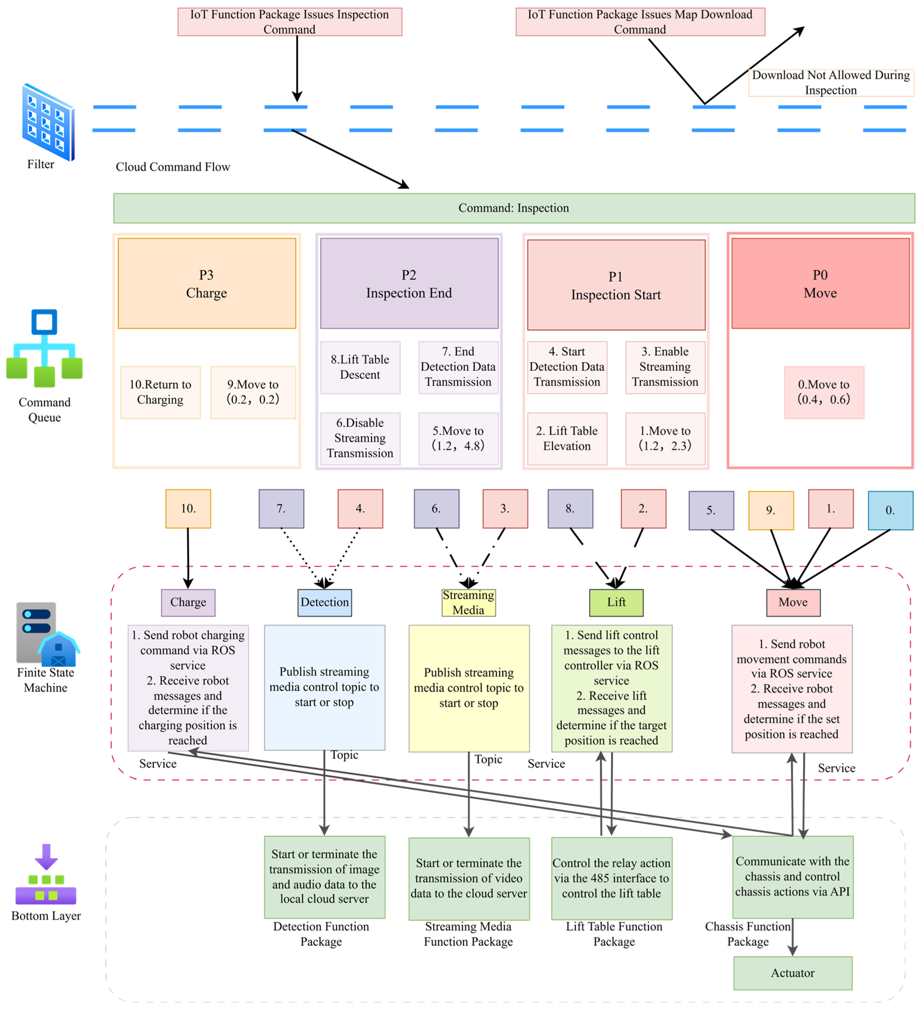
In terms of task organization, the module employs a finite-state machine to describe behavioral transitions among initialization, standby, inspection execution, abnormal handling, and stop states, while a task-blocking queue is used to manage the execution order of multi-step actions. For composite tasks such as waypoint-based inspection, the system does not treat the task as a single command; instead, it organizes it into multiple sequentially constrained substeps, including chassis movement, lifting-mechanism adjustment, image acquisition, state recording, and transition to the next waypoint. Through the combination of state-machine constraints and queue-based execution, the robot is able to maintain consistent action sequencing in complex scenarios and to reduce the impact of resource contention and disordered switching on task-execution stability. The internal scheduling framework is illustrated in Figure 10.
In terms of ROS 2 coordination, this module interacts with other functional modules through Topics, Services, and Actions, and the corresponding interface mapping is summarized in Table 5. Status broadcasting and asynchronous events are mainly implemented through Topic-based publication and subscription. One-time control requests are typically issued through Services. Tasks with longer execution times and intermediate feedback requirements are coordinated through Actions with modules such as chassis motion and lifting control. Based on this mechanism, the event-processing and task-scheduling module further maps upper-level task requests into executable invocation forms for the chassis-control node, lifting-control node, and peripheral-control node. During execution, it continuously receives status feedback, which is used to update state-machine conditions and adjust subsequent actions.
In terms of state management and abnormal handling, this module aggregates task-execution states, action-completion flags, and abnormal-event information, and uses them as the internal state basis of the robot-side control plane. When communication abnormalities, critical device failures, or unsatisfied execution conditions occur, the system can enter a safe state according to the current state-machine logic, for example, by stopping motion, locking execution units, and recording abnormal information. Therefore, the primary role of this module is to maintain execution ordering, state consistency, and controllability under abnormal conditions, rather than to replace the underlying device-control or sensing-data-processing modules.

3.3. Cloud Communication Mechanisms

Building upon the robot-side software modules, the system further incorporates communication mechanisms oriented toward the cloud platform to support remote task scheduling, video monitoring, and environmental data aggregation. These communication services can be grouped into two categories, namely the control link and the data link. The former is responsible for command delivery and execution-state feedback, whereas the latter is used for uploading video data, environmental parameters, and operational information. Given the differences among these services in latency sensitivity, reliability requirements, and bandwidth consumption, the system adopts a design strategy that combines control prioritization, data stratification, and abnormal-condition recovery. The mechanisms for cloud-based command delivery, video data upload, and environmental data upload are described in the following subsections.
For reproducibility, the main network and MQTT communication parameters used in the field implementation are summarized in Table 6, while the corresponding field network-layer measurements are reported in Section 4.2. These settings were selected according to the different latency, reliability, and bandwidth requirements of control commands, status feedback, environmental telemetry, alarms, and visual data.
In this configuration, control, acknowledgment, and alarm messages were assigned higher reliability, whereas periodic status messages were kept lightweight to reduce continuous communication load. Environmental telemetry was uploaded periodically and could also be triggered immediately when abnormal values were detected. When the MQTT session was interrupted, the robot attempted reconnection, restored topic subscriptions, and uploaded buffered messages after the link was recovered.

3.3.1. Cloud-Based Command Delivery Mechanism

The cloud-based command delivery mechanism is a core component of the robot control link, enabling remote task scheduling and command transmission from the cloud to the robot side. Control messages are organized using an MQTT-based publish/subscribe model. According to user operations or scheduling logic, the cloud backend generates structured task commands and publishes them to the robot via predefined control Topics. On the robot side, the IoT communication module continuously subscribes to the corresponding Topics and, upon receiving downlink messages, performs message reception, content parsing, and local forwarding. Rather than allowing the cloud to directly drive low-level actuators, the proposed system first maps cloud-issued commands into unified internal task requests and then forwards them to the local event-processing and task-scheduling module for execution management. This design ensures that remote control remains verifiable, interruptible, and closed-loop in terms of state feedback [32]. The overall framework for command access and execution is shown in Figure 11.
Cloud commands and local GUI commands enter the robot side through the MQTT communication interface and the GUI control interface, respectively, and are then merged into a unified ROS 2 service layer and routed to the central scheduling path. Subsequently, command arbitration, state evaluation, and sequential execution are performed through filtering, a task-blocking queue, and the event-processing main loop. The key idea of this design is to decouple multi-source command inputs from low-level actuation. Instead of allowing upper-layer scheduling logic to directly operate the chassis, lifting mechanism, or cameras, all commands are processed through a unified command-entry interface within the local control plane. This reduces action conflicts caused by multi-entry concurrent control and provides a structural basis for future extension to new control terminals, task types, and peripheral nodes.
Cloud-side messages are divided, according to service type, into control, status, acknowledgment, alarm, environmental data, and visual data Topics, as defined in Table 7. Control Topics are mainly used for commands such as task start, task stop, waypoint inspection, return-to-charge, and emergency stop. Status, acknowledgment, and alarm Topics are mainly used to return robot operating states, command-reception results, and abnormal events. Environmental data and visual data Topics are used to carry environmental telemetry and visual results generated during inspection.
During command parsing, the system is concerned not only with whether the required message fields are present, but more importantly with whether the command is executable under the current operating context. On the robot side, the command category is first identified according to the Topic type, after which the message payload undergoes deserialization, format validation, and integrity checking to confirm the presence of essential fields such as task identifier, target pose (x, y, θ), task type, priority, and timestamp. Parameter validity is then further examined, including whether the pose range is valid, whether the task type is supported, whether the priority complies with scheduling constraints, and whether the command timestamp satisfies timeliness requirements. Through these procedures, malformed, incomplete, duplicated, or expired control messages can be filtered out before entering the execution layer.
After basic validation is completed, the system performs semantic parsing in the context of the current operating state. In other words, command parsing evaluates not only whether a message is syntactically correct, but also whether it is executable at that moment. For example, when the robot is already performing navigation, a newly received movement command does not directly override the ongoing action; instead, it is inserted into a waiting queue according to priority and task type. Likewise, when the system is in abnormal-protection mode, global-stop state, or device-uninitialized state, the corresponding task request may be postponed, rejected, or converted into a recovery-related control event. For inspection commands composed of multiple waypoints, the parsing module further organizes the upper-level task semantics into a set of sequentially executable subtasks, which are then scheduled by the local task manager according to finite-state-machine logic.
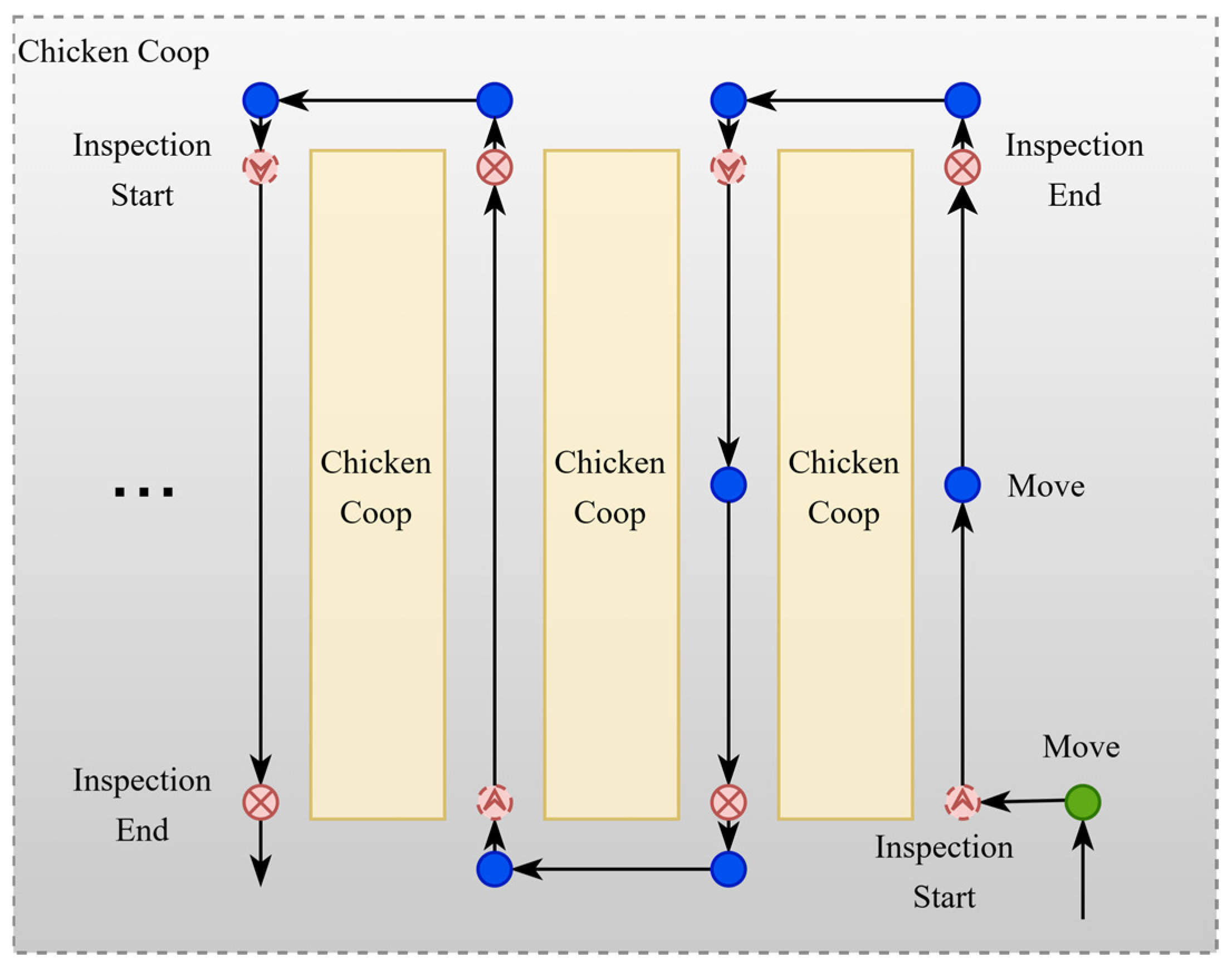
Inspection tasks are defined using structured waypoints, in which the target pose is represented as (x, y, θ), where x and y denote the planar position coordinates and θ denotes the heading angle. The task-type field specifies the semantic meaning of the corresponding waypoint. In this formulation, Move indicates motion to a designated position, Inspection Start and Inspection End denote the beginning and end of the inspection procedure, respectively, and Charge denotes return to the charging station after task completion. Based on this structure, the cloud can flexibly adjust inspection routes, stopping sequences, and waypoint-associated actions without modifying the underlying execution logic. A representative example of structured route organization is shown in Figure 12.
At the task-scheduling level, validated and semantically interpreted commands are delivered to the robot-side control plane, where they are uniformly organized by the event-processing and task-scheduling module according to the current operating state, interlock constraints, and task context, and are subsequently distributed to the chassis, lifting mechanism, and peripheral-control nodes. For Move commands, the system primarily invokes the chassis-navigation interface and monitors arrival feedback. For Inspection Start commands, the system enters the inspection state and coordinates navigation, lifting adjustment, image acquisition, and environmental data upload according to predefined logic. For Inspection End commands, the system terminates the current inspection procedure and releases related resources. For Charge commands, the system generates a navigation task toward the charging station and switches to the return-to-charge procedure. In this way, cloud-side commands do not directly drive individual actuators; instead, they are transformed into a controlled action chain through the sequence of cross-end command access, local state-aware parsing, and internal scheduling execution.
The command execution procedure follows the basic flow of “cloud publication-robot reception-command parsing-task scheduling-action execution-status return.” During execution, the robot continuously reports task states, action-completion flags, and abnormal events, enabling the cloud backend to perform remote monitoring and task tracking. Status feedback includes not only process markers such as “task started,” “executing,” and “completed,” but also error conditions such as navigation failure, communication abnormality, and actuator not-in-position, thereby providing the cloud platform with a traceable control loop. To cope with wireless-link fluctuations and unstable bandwidth in poultry house environments, reliable delivery is prioritized for control messages, while acknowledgment, duplicate-message suppression, and abnormal-event reporting are incorporated to improve scheduling-link robustness. The purpose of this mechanism is not to allow the cloud to perform fine-grained direct control over low-level actions, but rather to ensure that remote scheduling commands can be reliably received, correctly interpreted, and executed on the robot side in a controlled and feedback-enabled manner.

3.3.2. Video Data Upload Mechanism

The video data upload mechanism was designed to support both real-time preview and image retention during remote inspection. In the field implementation, the real-time preview channel was implemented as an RTSP-based H.264 streaming channel. The network cameras generated H.264 video streams, which were accessed through the internal Ethernet and then relayed to the cloud-side video service for remote preview. Continuous video frames were not transmitted through MQTT; MQTT was used for control messages, status feedback, alarms, environmental telemetry, and key-frame-related structured records. In parallel with the streaming channel, the robot extracted key frames at a fixed interval and uploaded them as independent visual records for process retention. Therefore, the video uplink was organized as two complementary channels: an RTSP-based real-time preview channel and a sampled key-frame upload channel.
As shown in Figure 13, the robot-side vision system acquires multi-camera video streams through the internal network, with video encoded in H.264 and transmitted at a resolution of 720p. This configuration provides a practical balance between image usability and bandwidth consumption. For real-time viewing, the system delivers continuous video preview to the cloud in a streaming manner, allowing remote observation of the current inspection state. For critical visual information generated during inspection, the robot extracts key frames at a fixed interval after video access and decoding and uploads these key frames or structured visual results as independent data units.
In addition to image content, each key-frame record includes metadata such as timestamp, camera identifier, robot pose, and task state, thereby supporting subsequent retrieval, playback, and process association. On the cloud side, real-time video and key-frame data are received and managed separately. Real-time streams are used for online monitoring, whereas key-frame data are used for process retention and result presentation. Compared with complete continuous video, key-frame data are more suitable for long-term storage and retrospective analysis of inspection processes.
In terms of transmission strategy, the system organizes the video link in the form of “streaming preview + periodic sampled upload.” This avoids treating full continuous video as the sole object for upload and storage, thereby reducing processing burden on the robot side and alleviating bandwidth pressure on the wireless link. For inspection-oriented applications, this design is more consistent with the practical requirement of combining real-time observation with selective visual record retention, while also helping maintain basic video-link availability under fluctuating network conditions.

3.3.3. Environmental Data Upload Mechanism

The environmental data upload mechanism is designed to enable continuous acquisition, transmission, and cloud-side aggregation of environmental parameters during inspection. The robot is equipped with sensors for temperature, humidity, air velocity, illuminance, and other environmental variables. After unified access through the RS-485-based device abstraction layer, these data are uploaded to the cloud according to predefined rules by the IoT communication module. In this way, environmental sensing results are transformed from on-site measurements into structured information that can be stored, visualized, and analyzed on the cloud platform.
Environmental data are encapsulated in a structured message format, typically including fields such as timestamp, current robot pose, sensor identifier, parameter type, and measured value. By attaching pose information to each message, environmental parameters can be associated with specific spatial locations along the robot’s inspection route, thereby supporting region-level statistics, spatial distribution analysis, and process traceability. For a mobile inspection platform, this mode of data organization is more suitable for subsequent application-oriented analysis than simple time-series recording alone.
Environmental data are uploaded to the cloud backend via MQTT and support both periodic transmission and event-triggered reporting. Periodic transmission is used to maintain continuous records of environmental conditions and is appropriate for routine monitoring and trend visualization. Event-triggered reporting is used to provide immediate upload when a parameter exceeds its threshold or undergoes a significant short-term variation, thereby improving responsiveness to critical environmental changes. By combining these two mechanisms, the system can balance data continuity and abnormal-event sensitivity without imposing excessive load on the control link.
After the cloud backend receives the environmental data, the data are stored, visualized, and statistically processed, and can be further combined with pose information for region-associated analysis. Compared with the video link, environmental telemetry imposes lower bandwidth demands, but places higher requirements on data-format consistency, sampling-cycle stability, and long-term accumulation. Therefore, the design emphasis of this mechanism is not on high-throughput transmission, but on stable upload behavior, unified data organization, and timely reflection of abnormal environmental conditions.

4. Results

4.1. Test Overview

To evaluate the availability and stability of the proposed communication system in a real caged broiler house, continuous field testing was conducted from 8 September 2025 to 5 January 2026, covering a total period of 120 d. The test spanned two actual production batches, including 45 d for the first batch and 62 d for the second batch, with an intermediate 13 d interval used for site cleaning, equipment maintenance, network adjustment, and system reset. The poultry house aisle was approximately 100 m in length, and the field environment was characterized by persistent high humidity, heavy dust, frequent equipment disturbance, and fluctuating wireless coverage.
During the test period, the system executed a total of 512 inspection tasks, covering the complete operational workflow, including task start/stop, waypoint-based inspection, return-to-charge, emergency stop, key-frame upload, and environmental telemetry reporting. Meanwhile, the cloud issued 6412 control commands, forming a relatively complete long-term operational dataset. The overall test arrangement and task scale are summarized in Table 8.

4.2. Network Condition Definition and Resource Monitoring

To make the latency and video availability results more reproducible, representative network-layer measurements were added to characterize the wireless conditions during field operation. The network condition was evaluated using robot-side received signal strength indicator (RSSI), packet loss rate, round-trip time (RTT), jitter, available uplink and downlink bandwidth, and MQTT reconnection records. RSSI was recorded from the robot-side Wi-Fi interface; packet loss, RTT, and jitter were obtained from periodic network probes between the robot and the cloud-side server; and the available bandwidth was measured through representative field sampling during inspection-related operation. According to these indicators, the field network was divided into normal, fluctuating, weak-network, and temporary-interruption conditions, as summarized in Table 9.
In this study, weak-network periods mainly referred to field sections or time windows in which RSSI decreased to approximately −70 to −78 dBm, packet loss increased to 3.0–8.0%, RTT increased to 150–300 ms, jitter increased to 45–90 ms, and the available uplink bandwidth decreased to approximately 1–3 Mbps. These periods were typically observed near the end of the aisle, in cage-shielded areas, or during short-term AP roaming and MQTT reconnection. Temporary interruptions were not treated as stable weak-network operation but were recorded separately as link-fluctuation or recovery events.
In addition to link-quality indicators, system resource usage was monitored to evaluate whether weak-network operation caused excessive computational or memory load on the robot side. CPU usage, memory usage, uplink and downlink traffic, buffer queue length, and MQTT reconnection frequency were compared under different network conditions, as shown in Table 10.
The results show that weak-network conditions mainly reduced the available uplink bandwidth and increased the buffer queue length and MQTT reconnection frequency. CPU and memory usage increased moderately, but no resource exhaustion or process crash was observed during the representative tests. This indicates that the link-recovery and buffered retransmission mechanisms increased the communication load to some extent, but the additional resource consumption remained within an acceptable range for field operation.

4.3. Control Link Performance

The evaluation of the control link was intended to verify whether cloud-side commands could be received, parsed, admitted into the local scheduling pipeline, and followed by valid feedback under real poultry house conditions. Four metrics were used: command delivery success rate, ACK validity rate, end-to-end control latency, and emergency-stop success rate. Command delivery success rate was calculated as the number of cloud-issued commands successfully parsed and admitted into the robot-side scheduling pipeline divided by the total number of cloud-issued commands. ACK validity rate was calculated as the proportion of commands for which the cloud received an acknowledgment with a matching cmd_id and a valid ack_state within the predefined timeout window. End-to-end control latency was measured from cloud-side command publication to the reception of the corresponding ACK by the cloud. Duplicate, expired, malformed, or unmatched ACK messages were excluded from the valid ACK count. Weak-network periods were identified according to the network condition definition in Section 4.2.
During the test period, the cloud issued a total of 6412 control commands. The overall command delivery success rate reached 99.53%, and the ACK validity rate reached 99.71%. Routine control commands, including task start/stop, waypoint navigation, and return-to-charge, remained generally stable throughout the field test. In addition, all 38 emergency-stop commands were successfully executed, corresponding to a success rate of 100%. Based on the network condition definition in Table 9, under normal network conditions, the median control latency was 182 ms, with a 95th-percentile latency of 426 ms. During weak-network periods, the median latency increased to 318 ms, and the 95th-percentile latency increased to 917 ms. The corresponding results are presented in Table 11.
To examine whether concurrent data transmission affected the control link, command records were further grouped according to the data-uplink state. The low-data-uplink condition refers to periods in which only routine status feedback and environmental telemetry were active, whereas concurrent control/data transmission refers to periods in which control commands were issued together with real-time video preview, key-frame upload, and environmental telemetry upload. As shown in Table 12, concurrent data transmission caused only a slight increase in control latency, while command delivery success rate and ACK validity rate remained close to those under low-data-uplink conditions.
These results indicate that the separated control/data link organization and control-priority strategy limited the interference of multi-source data transmission on command delivery.
From the observed failure samples, undelivered commands or invalid acknowledgments mainly occurred during short-term wireless-signal attenuation, reconnection windows on the robot side, and transient state conflicts during task switching. These findings indicate that the primary risks to the control link in the poultry house environment arise from field network fluctuation and state transition boundaries, rather than from fundamental protocol failure. Overall, the proposed system was able to meet the stability requirements of remote inspection tasks.

4.4. Data-Link Performance

The evaluation of the data link focused on whether visual and environmental information generated during inspection could be uploaded and converted into usable cloud-side records. Four metrics were used: real-time video availability, key-frame upload completion rate, environmental telemetry arrival rate, and event-triggered report arrival rate. Real-time video availability was calculated at the inspection-session level, based on whether the cloud-side preview channel was successfully established and remained decodable during inspection. A video session was counted as available when the RTSP preview stream could be established, and no continuous loss of decodable frames longer than 10 s occurred during the inspection task. Failed stream establishment or a continuous preview interruption longer than 10 s was counted as unavailable. Short stalls that recovered within this threshold were recorded as link fluctuations but were not counted as unavailable sessions. Key-frame upload completion rate was calculated as the number of key-frame records successfully received and stored by the cloud platform divided by the number of key-frame messages generated on the robot side. Environmental telemetry arrival rate was calculated as the number of complete telemetry records stored by the cloud platform divided by the number of telemetry messages generated by the robot-side sensing module. A telemetry record was considered valid only when the robot identifier, timestamp, sensor type, measured value, and pose-related information were complete. Event-triggered report arrival rate was calculated using the same rule for out-of-range or alarm-triggered messages.
The results show that, during the test period, the real-time video availability reached 97.50%, the key-frame upload completion rate reached 99.35%, the overall environmental telemetry arrival rate reached 98.96%, and the event-triggered report arrival rate reached 98.60%. Among these, the real-time video link was more susceptible to instantaneous bandwidth fluctuation and mainly manifested as preview stalling or short-term interruption during a small number of periods. By contrast, key-frame upload and environmental telemetry maintained higher completion levels due to the combined use of hierarchical transmission, buffered retransmission, and non-continuous full-frame transmission strategies. The relevant results are summarized in Table 13.
These results indicate that, under constrained network resources, the system prioritizes the retention of critical data and the visibility of key status information, rather than attempting to maintain continuous full-load transmission at all times. For long-term poultry house inspection, this design is more consistent with practical deployment requirements.

4.5. Mission-Level Completion and Recovery Capability

The availability of command delivery or data upload alone is not sufficient to demonstrate long-term operational suitability in production-oriented scenarios. Therefore, task-level closed-loop completion was further used to assess the engineering usability of the system. In this study, task completion was defined as successful cloud-side task delivery, completion of waypoint navigation, lifting, and data-acquisition actions on the robot side, and return of task status together with key data to the cloud. Recovery success was defined as successful continuation and completion of a task after link interruption or transient abnormality through automatic reconnection, buffered retransmission, or local state recovery, without requiring manual task reconfiguration.
Among the 512 inspection tasks, 485 were completed directly on the first attempt, 18 were completed after automatic recovery from short-term communication abnormalities, and 9 were terminated due to persistent weak-network conditions, manual obstacle avoidance, or equipment maintenance, corresponding to an overall task completion rate of 98.24%. During the test period, a total of 37 clearly observable link fluctuation events were recorded, among which 34 recovered within 60 s and successfully restored critical message subscriptions, while only 3 required manual intervention. The relevant statistics are presented in Table 14. These results indicate that the system does not depend on ideal network conditions; rather, most link fluctuations can be contained within a recoverable range through reconnection, retransmission, and state-machine protection.

4.6. Representative Field Operation Cases

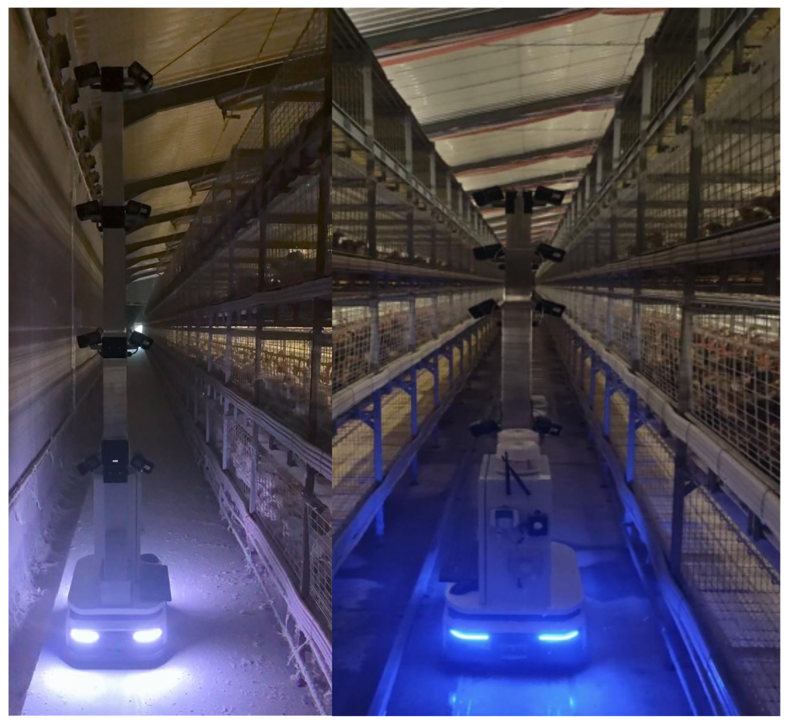
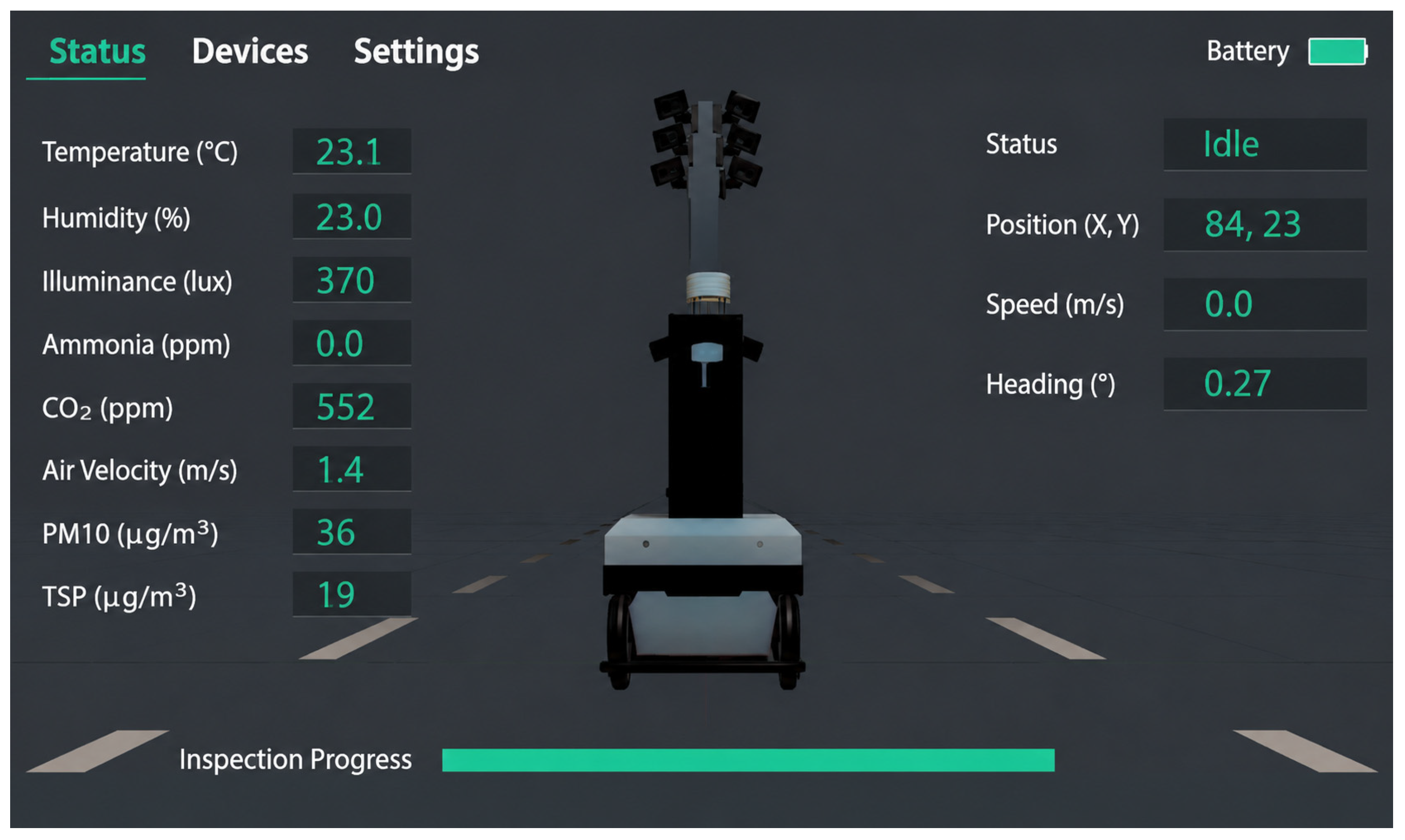
To strengthen the correspondence between the quantitative results and the actual field operation, only two representative figures are retained in this study. Figure 14 shows the on-site operation of the inspection robot in the corridor of the caged broiler house, reflecting the actual working conditions under which the robot performed movement, stopping, and multi-tier cage observation tasks within a long and narrow aisle. Figure 15 presents the robot status information during field inspection tasks, corresponding to the centralized presentation of task state, device state, and operational information on the platform side.
Taken together with Figure 14 and Figure 15 and Table 5, Table 6, Table 7 and Table 8, the results show that the robot side, network layer, and cloud platform formed a traceable closed loop around the same inspection task. Under favorable network conditions, the system was able to simultaneously maintain command delivery, status return, and data upload. When short-term link fluctuations occurred, the system preferentially preserved the reachability of control commands and critical data units and resumed the remaining workflow after link recovery. This is consistent with the statistical results presented above and demonstrates the engineering feasibility of deploying the proposed communication system in real caged broiler-house environments.

5. Discussion

This study proposed and implemented a communication-oriented robotic system architecture for inspection in caged broiler houses, in which internal robot-side coordination and robot–cloud communication were integrated into a unified end-to-end closed loop. The architecture was built on ROS 2 for internal coordination and MQTT for cross-end message exchange and was further enhanced with link reconnection, buffered retransmission, and finite-state-machine-based scheduling mechanisms. These design choices were introduced to address practical constraints commonly encountered in poultry house environments, including weak-network fluctuation, high humidity, heavy dust, field disturbance, and concurrent multi-service traffic.
Field test results demonstrated that, over a continuous 120 d period from 8 September 2025 to 5 January 2026, the system completed 512 inspection tasks and processed 6412 cloud-issued control commands. For the control link, the overall command delivery success rate reached 99.53%, while the ACK validity rate reached 99.71%, and all 38 emergency-stop commands were executed successfully. Under weak-network conditions, the system mainly exhibited an increase in latency tail rather than evident systemic failure. For the data link, the real-time video availability reached 97.50%, the key-frame upload completion rate reached 99.35%, the overall environmental telemetry arrival rate reached 98.96%, and the event-triggered report arrival rate reached 98.60%. At the mission level, 485 of the 512 inspection tasks were completed directly on the first attempt, 18 were completed after automatic recovery from short-term communication abnormalities, and only 9 were terminated, resulting in an overall task completion rate of 98.24%. Among 37 clearly observable link fluctuation events, 34 were automatically recovered within 60 s, with critical message subscriptions successfully restored.
These results indicate that the primary contribution of this work does not lie in proposing a new communication protocol or improving a single navigation or perception algorithm, but in establishing and validating a deployable, recoverable, and observable communication framework for caged broiler inspection robots. By closing the loop among cloud-side scheduling, robot-side execution, status feedback, and data retention, the proposed system provides a practical implementation pathway for the engineering deployment of remote inspection robots in smart poultry-farming scenarios.
Several limitations remain to be addressed in future work. First, the present validation was conducted on a single-robot system in one commercial caged broiler house. Although the layered architecture can be adapted to other poultry house scenarios, its deployment parameters, including access-point density, broker location, topic organization, camera number and resolution, key-frame sampling interval, telemetry frequency, and buffer capacity, should be adjusted when the house layout, network scale, or sensing configuration changes. Therefore, the field performance of the system still needs to be revalidated under different poultry house conditions or multi-robot deployments. Second, the current link protection strategy is mainly rule-based. Future work will explore semantic-priority-based adaptive QoS scheduling, so that control commands, acknowledgments, alarms, task states, environmental telemetry, key frames, and video streams can be assigned different transmission priorities according to task urgency and network quality. Edge computing nodes or lightweight digital-twin models may also be introduced to support local caching, task-state maintenance, preliminary data screening, and synchronized representation of robot and communication states, thereby reducing cloud dependency during short-term link fluctuations. In addition, the relationship between communication-quality indicators and poultry-production indicators requires further investigation.

Author Contributions

D.H.: Writing—Original draft, Software, Methodology, Investigation, Validation, Data curation, Writing—review and editing; K.Y.: Writing—review and editing, Data curation, Investigation, Supervision; H.W.: Investigation, Data curation, Methodology; J.S.: Investigation, Data curation, Methodology; H.Z.: Data curation, Methodology; S.L.: Investigation, Data curation, Methodology; C.C.: Resources, Supervision, Methodology, Investigation, Funding acquisition. All authors have read and agreed to the published version of the manuscript.

Funding

(1) “Supported by China Agriculture Research System of MOF and MARA” (CARS-41); (2) “Supported by National Key R&D Program of China” (2023YFD2000800); (3) “Supported by the 2025 Young Scientific and Technological Talents Development Fund Program of Tianjin Agricultural University” (2025QNKJ24).

Data Availability Statement

The data are not publicly available at this time due to ongoing related research but are available from the corresponding author upon reasonable request.

Acknowledgments

The authors thank the staff of the commercial poultry farm for their assistance during field deployment and long-term system testing.

Conflicts of Interest

The authors declare no conflicts of interest.

Abbreviations

The following abbreviations are used in this manuscript:
ACKAcknowledgment
APAccess Point
CPUCentral Processing Unit
DDSData Distribution Service
IoTInternet of Things
MQTTMessage Queuing Telemetry Transport
QoSQuality of Service
ROS 2Robot Operating System 2
RSSIReceived Signal Strength Indicator
RTTRound-Trip Time
SLAMSimultaneous Localization and Mapping
TSPTotal Suspended Particulates

References

  1. Terence, S.; Immaculate, J.; Raj, A.; Nadarajan, J. Systematic review on Internet of Things in smart livestock management systems. Sustainability 2024, 16, 4073. [Google Scholar] [CrossRef]
  2. Ojo, R.O.; Ajayi, A.O.; Owolabi, H.A.; Oyedele, L.O.; Akanbi, L.A. Internet of Things and machine learning techniques in poultry health and welfare management: A systematic literature review. Comput. Electron. Agric. 2022, 200, 107266. [Google Scholar] [CrossRef]
  3. Park, M.; Britton, D.; Daley, W.; McMurray, G.; Navaei, M.; Samoylov, A.; Usher, C.; Xu, J. Artificial intelligence, sensors, robots, and transportation systems drive an innovative future for poultry broiler and breeder management. Anim. Front. 2022, 12, 40–48. [Google Scholar] [CrossRef] [PubMed]
  4. Özentürk, U.; Chen, Z.; Jamone, L.; Versace, E. Robotics for poultry farming: Challenges and opportunities. Comput. Electron. Agric. 2024, 226, 109411. [Google Scholar] [CrossRef]
  5. Yang, D.; Cui, D.; Ying, Y. Development and trends of chicken farming robots in chicken farming tasks: A review. Comput. Electron. Agric. 2024, 221, 108916. [Google Scholar] [CrossRef]
  6. Godinho, A.; Vicente, R.; Silva, S.; Coelho, P.J. Wireless environmental monitoring and control in poultry houses: A conceptual study. IoT 2025, 6, 32. [Google Scholar] [CrossRef]
  7. Liu, M.; Chen, H.; Zhou, Z.; Du, X.; Zhao, Y.; Ji, H.; Teng, G. Development of an intelligent service platform for a poultry house facility environment based on the Internet of Things. Agriculture 2024, 14, 1277. [Google Scholar] [CrossRef]
  8. Vroegindeweij, B.A.; Blaauw, S.K.; IJsselmuiden, J.M.M.; van Henten, E.J. Evaluation of the performance of PoultryBot, an autonomous mobile robotic platform for poultry houses. Biosyst. Eng. 2018, 174, 295–315. [Google Scholar] [CrossRef]
  9. Balthazar, G.d.R.; Silveira, R.M.F.; Soares, T.C.; Silva, I.J.O. RobôFrango: Proof of concept of a mobile biosensor robot for environmental monitoring in broiler houses. Results Eng. 2025, 28, 107796. [Google Scholar] [CrossRef]
  10. Ma, W.; Wang, X.; Yang, S.X.; Xue, X.; Li, M.; Wang, R.; Yu, L.; Song, L.; Li, Q. Autonomous inspection robot for dead laying hens in caged layer house. Comput. Electron. Agric. 2024, 227, 109595. [Google Scholar] [CrossRef]
  11. Zhang, Y.; Lai, Z.; Wang, H.; Jiang, F.; Wang, L. Autonomous navigation using machine vision and self-designed fiducial marker in a commercial chicken farming house. Comput. Electron. Agric. 2024, 224, 109179. [Google Scholar] [CrossRef]
  12. Luu, T.; Nguyen, Q.; Tran, T.; Tran, M.; Ding, S.; Kua, J.; Hoang, T. Enhancing real-time robot teleoperation with immersive virtual reality in industrial IoT networks. Int. J. Adv. Manuf. Technol. 2025, 139, 6233–6257. [Google Scholar] [CrossRef]
  13. Han, Y.; An, Y.; Li, S.; Wang, N.; Niu, Y.; Zhang, M.; Li, H. Lane navigation control method and equipment of chicken house based on 2D LiDAR. Comput. Electron. Agric. 2025, 239, 110993. [Google Scholar] [CrossRef]
  14. Jiang, J.; Zhang, T.; Li, K.; Deng, H.; Yang, J. LiDAR-based 3D SLAM for autonomous navigation in stacked cage farming houses: An evaluation. Comput. Electron. Agric. 2025, 230, 109885. [Google Scholar] [CrossRef]
  15. Qi, F.; Zhao, X.; Shi, Z.; Li, H.; Zhao, W. Environmental Factor Detection and Analysis Technologies in Livestock and Poultry Houses: A Review. Agriculture 2023, 13, 1489. [Google Scholar] [CrossRef]
  16. Beniwal, G.; Singhrova, A. A systematic literature review on IoT gateways. J. King Saud Univ. Comput. Inf. Sci. 2022, 34, 9541–9563. [Google Scholar] [CrossRef]
  17. Carreira, R.; Costa, N.; Ramos, J.; Frazão, L.; Pereira, A. A ROS 2-based gateway for modular hardware usage in heterogeneous environments. Sensors 2024, 24, 6341. [Google Scholar] [CrossRef]
  18. Song, B.-Y.; Choi, H. ROS gateway: Enhancing ROS availability across multiple network environments. Sensors 2024, 24, 6297. [Google Scholar] [CrossRef]
  19. Xing, H.; Liu, Y.; Chen, J.; Li, W.; Ding, L.; Tavakoli, M. Variable admittance control for door opening with a wheeled mobile manipulator considering ground obstacles. Intell. Serv. Robot. 2026, 19, 41. [Google Scholar] [CrossRef]
  20. Chai, A.; Yin, W.; Lian, M.; Sun, Y.; Guo, C.; Wang, L.; Fang, Z. DUA-MQTT: A distributed high-availability message communication model for the Industrial Internet of Things. Sensors 2025, 25, 5071. [Google Scholar] [CrossRef]
  21. An, D.; Joo, H.; Kim, H. Enabling low-latency digital twins for large-scale UAV networks using MQTT-based communication framework. ICT Express 2025, 11, 264–269. [Google Scholar] [CrossRef]
  22. Freitas, L.; Silva, M.; Vale, G.; Avram, C.; Lopes, H.; Pereira, F.; Leal, N.; Machado, J. OPC UA and MQTT performance analysis within a unified namespace context. Internet Things 2025, 33, 101734. [Google Scholar] [CrossRef]
  23. Sasaki, R.; Takefusa, A.; Nakada, H.; Oguchi, M. Communication performance of ROS and ROS 2-based IoT systems for smart home applications. IEICE Trans. Inf. Syst. 2025, E108.D, 895–905. [Google Scholar] [CrossRef]
  24. Zhang, J.; Yu, X.; Ha, S.; Peña Queralta, J.; Westerlund, T. Comparison of Middlewares in Edge-to-Edge and Edge-to-Cloud Communication for Distributed ROS 2 Systems. J. Intell. Robot. Syst. 2024, 110, 162. [Google Scholar] [CrossRef]
  25. Muhammed, D.; Ahvar, E.; Ahvar, S.; Trocan, M.; Montpetit, M.-J.; Ehsani, R. Artificial Intelligence of Things (AIoT) for smart agriculture: A review of architectures, technologies and solutions. J. Netw. Comput. Appl. 2024, 228, 103905. [Google Scholar] [CrossRef]
  26. Yu, P.; Teng, F.; Zhu, W.; Shen, C.; Chen, Z.; Song, J. Cloud-edge-device collaborative computing in smart agriculture: Architectures, applications, and future perspectives. Front. Plant Sci. 2025, 16, 1668545. [Google Scholar] [CrossRef]
  27. Fernández, R.; Navas, E.; Rodríguez-Nieto, D.; Rodríguez-González, A.A.; Emmi, L. DigiHortiRobot: An AI-driven digital twin architecture for hydroponic greenhouse horticulture with dual-arm robotic automation. Future Internet 2025, 17, 347. [Google Scholar] [CrossRef]
  28. Rahman, H.; Shah, U.M.; Riaz, S.M.; Kifayat, K.; Moqurrab, S.A.; Yoo, J. Digital twin framework for smart greenhouse management using next-gen mobile networks and machine learning. Future Gener. Comput. Syst. 2024, 156, 285–300. [Google Scholar] [CrossRef]
  29. Nkwocha, C.L.; Adewumi, A.; Folorunsho, S.O.; Eze, C.; Jjagwe, P.; Kemeshi, J.; Wang, N. A comprehensive review of sensing, control, and networking in agricultural robots: From perception to coordination. Robotics 2025, 14, 159. [Google Scholar] [CrossRef]
  30. Ungurean, I. Integrating fieldbus and data-centric middleware: An STM32 Modbus master gateway for DDS-based IIoT systems. Technologies 2025, 13, 526. [Google Scholar] [CrossRef]
  31. Cuadros Zegarra, E.; Barrios Aranibar, D.; Cardinale, Y. IoRT-based middleware for heterogeneous multi-robot systems. J. Sens. Actuator Netw. 2024, 13, 87. [Google Scholar] [CrossRef]
  32. Liu, C.; Zhang, Y.; Ma, L.; Huang, Y.; Liu, K.; Wang, G. Unmanned aerial vehicle–unmanned ground vehicle centric visual semantic simultaneous localization and mapping framework with remote interaction for dynamic scenarios. Drones 2025, 9, 424. [Google Scholar] [CrossRef]
Figure 1. Architecture diagram.
Electronics 15 02406 g001
Figure 2. Hardware Architecture.
Electronics 15 02406 g002
Figure 3. Workflow of the control link.
Electronics 15 02406 g003
Figure 4. Workflow of the data link.
Electronics 15 02406 g004
Figure 5. Hardware communication topology of the robot side.
Electronics 15 02406 g005
Figure 6. ROS 2-based software communication and task-coordination modules.
Electronics 15 02406 g006
Figure 7. Uplink and downlink message workflow for robot–cloud interaction.
Electronics 15 02406 g007
Figure 8. Data and control-flow organization for RS-485 field devices.
Electronics 15 02406 g008
Figure 9. Workflow of video-stream access, key-frame extraction, and image publication.
Electronics 15 02406 g009
Figure 10. State-machine-based task execution and abnormal-handling workflow.
Electronics 15 02406 g010
Figure 11. Workflow of cloud communication.
Electronics 15 02406 g011
Figure 12. Structured inspection route and waypoint semantics.
Electronics 15 02406 g012
Figure 13. Real-time video preview and key-frame upload workflow.
Electronics 15 02406 g013
Figure 14. On-site operation of the inspection robot in the corridor of the caged broiler house.
Electronics 15 02406 g014
Figure 15. Robot status information during field inspection tasks.
Electronics 15 02406 g015
Table 1. Comparison of representative studies from a communication system perspective.
Study/SystemMain FocusRobot-Side CoordinationRobot-Cloud CommunicationWeak-Network/Recovery ConsiderationField-Validation Focus
PoultryBotPlatform feasibility and auxiliary inspectionNot the primary focusNot the primary focusNot explicitly discussedRobot operation in poultry houses
RobôFrangoMobile environmental monitoringPartially involvedMainly data acquisition-orientedNot explicitly discussedProof-of-concept monitoring
Navigation/inspection studiesNavigation, localization, or abnormal detectionTask-specificUsually not centralUsually not centralAlgorithm or task performance
Proposed systemCommunication system for caged broiler inspection robotsEthernet, RS-485, and ROS 2 coordinationMQTT-based task, status, alarm, and data interactionReconnection, buffering, ACK, and abnormal handling120-day communication-oriented field test
Table 2. Environmental sensors and their functional roles.
Sensor CategoryParametersFunctional Role
Temperature and humidityTemperature: 0–60 °C;
relative humidity:
0–100% RH
Used to characterize the thermal environment inside the poultry house and to support ventilation, cooling, and heating management.
Illuminance0–20,000 lxUsed to reflect the indoor light environment and to support supplemental-light management and environmental assessment during inspection.
Air velocity0–10 m/sUsed to evaluate airflow organization and ventilation uniformity, helping identify locally under-ventilated or over-ventilated areas.
CO20–5000 ppmUsed to indicate indoor air-exchange conditions and to assess whether the minimum ventilation rate is sufficient.
Ammonia0–100 ppmUsed to monitor harmful gas accumulation and to assess air-quality-related environmental risk.
PM100–1000 μg/m3Used to characterize inhalable particulate burden and reflect dust exposure levels in the poultry house.
TSP0–10 mg/m3Used to indicate the overall concentration of suspended particulate matter and to support the assessment of total dust pollution.
Table 3. Design rationale for the main communication technologies used in the proposed system.
Technology/MechanismMain RoleReason for Selection
ROS 2Coordinates robot-side software modulesSupports modular nodes, publish/subscribe communication, services, and actions, which helps separate device access, task scheduling, and data processing.
Industrial EthernetConnects cameras and chassis-related network devicesProvides stable bandwidth for video streams and motion-related communication inside the robot.
RS-485 with Modbus RTUConnects sensors, relays, and lifting actuatorSuitable for field-device access, multi-node wiring, and register-based control in harsh poultry house environments.
MQTTSupports robot-cloud task, status, alarm, and telemetry messagesLightweight topic-based messaging fits remote communication under fluctuating wireless coverage.
Streaming preview + key-frame uploadSupports real-time viewing and visual data retentionBalances online monitoring, storage cost, and bandwidth pressure better than full continuous video upload alone.
Control/data link separationOrganizes different service flowsAllows control commands and key status feedback to be prioritized when network quality decreases.
Table 4. Abstraction of field devices and ROS 2 interfaces.
Device TypeUnderlying CommunicationUnderlying ProtocolROS Interface TypePublished/Called ContentUpper-Level Function
Environmental data acquisition moduleRS-485Modbus RTUTopicTemperature, humidity, air velocity, illuminance, and other environmental parametersEnvironmental monitoring and cloud upload
Relay control moduleRS-485Modbus RTUServiceRelay energized/de-energized statePeripheral device start/stop control
Lifting actuatorRS-485Modbus RTUService/ActionTarget height setting and current-position feedbackCamera lifting and viewpoint adjustment
Chassis status interfaceEthernetNative device protocolTopic/ActionPose, velocity, and navigation targetMotion control and status feedback
Device abnormal-state interfaceRS-485Modbus RTUTopicFault code, timeout, and abnormal-state flagSafety interlock and abnormal-event reporting
Table 5. Mapping between task events and ROS 2 interfaces.
Task Event/Control RequestROS 2 Interface TypeTarget NodeMain InputMain Output/FeedbackDescription
Start inspection taskServicetask_manager_nodetask_id, route_idAcceptance result, task enters inspection stateUsed to trigger a complete inspection task
Stop inspection taskServicetask_manager_nodetask_idStop result, task enters termination stateUsed to terminate the current task
Waypoint navigationActionchassis_nav_nodetarget_pose (x, y, θ)Current position, navigation completion flagSuitable for long-duration execution with intermediate feedback
Lift adjustmentService/Actionlift_control_nodetarget_heightCurrent height, action completion stateCan be implemented as a one-time request or a continuous action
Relay controlServicerelay_control_noderelay_id, switch_stateControl execution resultUsed for peripheral device start/stop control
Environmental data publicationTopicenv_sensor_nodeSensor measurementsPeriodic environmental messagesRepresents continuously uploaded state data
Visual key-frame publicationTopicvision_nodeImage frame/detection resultImage message/structured resultSubscribed to by the task-scheduling and IoT communication modules
Abnormal-event broadcastTopicalarm_manager_nodealarm_type, alarm_levelAbnormal-state broadcastUsed for alarm propagation and state-machine switching
Emergency stopService/Topicsafety_manager_nodestop_flagStop confirmation, safety-state flagUsed to rapidly force the robot into a safe state
Table 6. Network configuration and MQTT communication parameters used in the field implementation.
ParameterSetting
Wi-Fi topologyMulti-AP coverage along the 100 m poultry house aisle, connected through the farm gateway
Broker/cloud serverMQTT broker and cloud backend deployed on the same cloud-side server or cloud-side network
MQTT clientOne active robot-side MQTT client
MQTT versionMQTT 3.1.1
Keep-alive30 s
Reconnection5 s initial interval; topic resubscription after reconnection
Control/ACK/alarm QoSQoS 1
Periodic status QoSQoS 0
Environmental telemetry QoSQoS 1
Status frequency3 s
Environmental telemetry frequency5 s
Key-frame sampling interval0.5 s
Buffer sizeUp to 2000 structured messages
Buffer policyCritical messages retained first; outdated periodic status may be discarded
Duplicate suppressionBased on cmd_id and timestamp
Table 7. MQTT Topics and message definitions for cloud communication.
Topic CategoryTopic ExampleMain Message FieldsDescription
Control Topic/robot/{id}/cmdcmd_type, task_id, target_pose (x, y, θ), params, priority, timestampUsed to deliver control commands such as task start, stop, waypoint inspection, return to charging, and emergency stop
Status Topic/robot/{id}/statustask_id, state, current_pose, battery, net_state, timestampUsed to return robot operating states, task-execution states, and online status
Acknowledgment Topic/robot/{id}/ackcmd_id, ack_state, error_code, timestampUsed to report command reception, parameter-validation results, and execution-acceptance feedback
Alarm Topic/robot/{id}/alarmalarm_type, alarm_level, description, timestampUsed to upload abnormal information such as device faults, communication failures, and safety-interlock triggers
Environmental data Topic/robot/{id}/envpose, sensor_id, data_type, value, timestampUsed to upload environmental telemetry such as temperature, humidity, air velocity, and illuminance
Visual data Topic/robot/{id}/visionframe_id, camera_id, pose, result_type, timestampUsed to upload key-frame indices or structured visual results
Table 8. Summary of the long-term field test arrangement and task scale.
ItemStatistical BasisResultDescription
Test periodContinuous field test2025.9–2026.1Total duration: 120 d
Batch compositionActual production batches45 days + 62 daysIntermediate 13 d used for cleaning and maintenance
Total inspection tasksComplete task-level closed loops512Including routine inspection, return-to-charge, and recovery-completed tasks
Total commandsCloud-issued control commands6412Including start/stop, waypoint navigation, return-to-charge, emergency stop, and mode switching
Key-frame uploadsValid key-frame records18,736Periodically sampled and uploaded during task execution
Environmental telemetry recordsValid telemetry messages24,580Including temperature, humidity, CO2, NH3, air velocity, and illuminance
Table 9. Definition of network conditions during field tests.
Network ConditionRSSI RangePacket Loss RateRTTJitterUplink BandwidthDownlink BandwidthMQTT
Reconnection
Typical
Situation
Normal
network
−45 to −60 dBm0–1.0%30–80 ms5–18 ms8–12 Mbps10–15 Mbps0–1 times/hNear AP or well-covered aisle sections
Fluctuating network−60 to −70 dBm1.0–3.0%80–150 ms18–45 ms3–8 Mbps5–10 Mbps1–3 times/hAP transition area or partial cage shielding
Weak
network
−70 to −78 dBm3.0–8.0%150–300 ms45–90 ms1–3 Mbps2–5 Mbps3–6 times/hEnd of aisle, cage shielding, or roaming area
Temporary interruption<−78 dBm or disconnected>8.0%>300 ms or timeout>90 ms or unstable<1 Mbps<2 Mbpsfrequent
reconnecting
Short-term disconnection or MQTT reconnection window
Table 10. System resource usage under different network conditions.
Operating ConditionCPU UsageMemory UsageUplink TrafficDownlink TrafficBuffer Queue LengthMQTT Reconnection
Normal
network
38.6 ± 5.4%46.8 ± 4.9%6.8 ± 1.7 Mbps0.42 ± 0.15 Mbps0–4 messages0–1 times/h
Fluctuating network42.9 ± 6.1%49.7 ± 5.3%3.9 ± 1.2 Mbps0.39 ± 0.14 Mbps3–18 messages1–3 times/h
Weak
network
47.5 ± 7.2%54.2 ± 6.1%1.8 ± 0.6 Mbps0.35 ± 0.12 Mbps12–46 messages3–6 times/h
Table 11. Control link performance statistics during field operation.
Command TypeNumber of CommandsDelivery Success Rate (%)ACK Validity Rate (%)Remarks
Task start/stop86499.6599.77Only a few cases exceeded the weak-network timeout window
Waypoint navigation/inspection498299.4899.69Main control service
Return-to-charge52899.4399.62More sensitive to network fluctuation and chassis-state interaction
Emergency stop38100.00100.00Highest-priority safety command
Overall641299.5399.71Control link remained generally stable
Table 12. Control link performance under different data-uplink loads.
Operating ConditionNumber of CommandsDelivery Success Rate (%)ACK Validity Rate (%)Median Latency (ms)P95 Latency (ms)
Low data-uplink load128699.6199.77176411
Concurrent control/data transmission512699.5199.69189458
Table 13. Uplink performance of visual data and environmental telemetry.
Link TypeStatistical ObjectTotalValid Arrival/CompletionResult (%)
Real-time video previewInspection video sessions512499 available97.50
Key-frame uploadKey-frame messages18,73618,615 completed99.35
Environmental telemetry uploadTelemetry messages24,58024,324 arrived98.96
Event-triggered reportingOut-of-range/alarm messages143141 arrived98.60
Table 14. Task-level completion and link-recovery statistics.
ItemNumber of Tasks/EventsRatio (%)Description
Tasks completed directly on first attempt48594.73Completed without link recovery
Tasks completed after automatic recovery183.52Completed after reconnection/retransmission
Aborted tasks91.76Mainly related to persistent weak network or manual intervention
Link fluctuation events37Defined as perceptible communication abnormalities
Automatically recovered within 60 s3491.89Critical subscriptions and status return restored
Requiring manual intervention38.11Occurred during maintenance or prolonged network interruption
Disclaimer/Publisher’s Note: The statements, opinions and data contained in all publications are solely those of the individual author(s) and contributor(s) and not of MDPI and/or the editor(s). MDPI and/or the editor(s) disclaim responsibility for any injury to people or property resulting from any ideas, methods, instructions or products referred to in the content.