Article

Flexible Grid-Connected/Off-Grid Switching Control Strategy for Storage Inverter

1
State Grid Hunan Electric Power Company Limited Research Institute, Changsha 410200, China
2
School of Electronic Information, Central South University, Changsha 410075, China
*
Authors to whom correspondence should be addressed.
Electronics 2026, 15(11), 2354; https://doi.org/10.3390/electronics15112354
Submission received: 26 April 2026 / Revised: 19 May 2026 / Accepted: 25 May 2026 / Published: 29 May 2026

Abstract

Taking a dual-mode grid-connected/off-grid storage inverter as the research subject, control models for both grid-connected and off-grid operation modes were established. For the grid-to-off-grid transition, an improved adaptive active frequency drift islanding detection algorithm was proposed, which employs a cubic power-based detection method when frequency deviation is small to reduce positive feedback speed, and a parabola-based detection method when frequency deviation is large to enhance positive feedback speed. Compared with the traditional active frequency drift islanding detection algorithm, the proposed method can ensure islanding detection speed while effectively reducing the current total harmonic distortion during grid-connected operation. Experiments conducted on a storage inverter prototype demonstrated stable operation in both grid-connected and off-grid modes. The results indicate that the proposed control strategy enables rapid identification of operating conditions and mode switching, significantly improving the stability and reliability of the inverter during transition, thus laying a foundation for the autonomous operation of dynamic microgrids.

1. Introduction

Against the backdrop of the escalating energy crisis and worsening environmental problems, renewable energy sources such as photovoltaic (PV) and wind power have been widely adopted, with the installed capacity of new energy power equipment registering steady annual growth [1]. Constructing a new power system dominated by new energy has become a crucial direction for the transformation and upgrading of power systems [2]. However, the output power of PV systems is constrained by factors including light intensity and temperature, exhibiting randomness and intermittency, which significantly impairs grid-connected stability [3,4,5]. In contrast, energy storage systems (ESSs) can effectively regulate output power, suppress PV power fluctuations [6], and enhance system stability. Therefore, ESS microgrids play a pivotal role in improving the reliability of PV power generation and the stability of grid connection.
Aiming at the off-grid and grid-connected control of inverters in ESS microgrids, this paper introduces the quasi-proportional resonant controller [7] and repetitive controller based on the internal model principle (IMP) to suppress disturbances and harmonics [8,9], as well as to improve the steady-state accuracy of the system. The ESS inverter with off-grid/grid-connected dual-mode operation is capable of switching between the two operating modes. When the inverter operating in grid-connected mode detects an islanding event caused by a grid power outage, it will switch to the off-grid mode. Islanding detection algorithms are mainly classified into three categories: passive, active, and hybrid types [10,11]. Passive algorithms mainly include overvoltage/undervoltage detection, overfrequency/underfrequency detection, and impedance detection for the system, which feature simple implementation but suffer from detection blind zones and are prone to maloperation under grid disturbances [12,13,14]. Active algorithms inject a disturbance term into the inverter’s output current, and the frequency will exceed the limit to trigger protection in the event of islanding. This method greatly reduces the detection blind zones but also degrades the power quality of the system. At present, active islanding detection methods based on signal injection strategies have been extensively investigated. References [15,16,17] all propose improved methods based on passive impedance detection, which realize islanding detection by analyzing the impedance characteristics before and after islanding through synchronous signal injection. However, these methods require injecting harmonics into the system, and the harmonic signals of multiple parallel-connected units are prone to mutual interference. Ref. [18] combines active and passive methods, taking both voltage and the rate of change of active power as the criteria for islanding detection, which can reduce the impact of active injected disturbances on power quality and avoid misjudgment in passive detection. However, this method is relatively complicated. Ref. [19] proposes a novel islanding detection method applicable to both grid-following and grid-forming inverters without additional communication. This method injects negative-sequence current into the grid and identifies islanding by detecting the voltage unbalance generated by the inverter at the point of common coupling, which is not suitable for single-phase inverters. Ref. [20] analyzes the output impedance characteristics of grid-connected inverters on the basis of the traditional active frequency drift (AFD) method, quantifies the interaction between AFD parameters and grid impedance, and proves that the system will become unstable due to insufficient phase margin after islanding occurs, so that the islanding state can be identified through frequency detection. However, the harmonic distortion of grid-connected current is still not taken into consideration. Ref. [21] puts forward an active islanding detection technology based on the mean absolute frequency deviation, which achieves effective islanding detection with low current distortion.
Aiming at the grid-connected/off-grid switching process of the inverter, to reduce the impact of islanding detection on grid-connected power quality while improving islanding detection performance, this paper proposes an improved positive feedback active frequency shift islanding detection algorithm, which adopts different positive feedback rates for different frequency deviation ranges. Compared with traditional islanding detection algorithms, such as positive feedback active frequency drift and impedance detection, this method can reduce the impact of islanding detection on grid-connected current harmonics without slowing down the islanding detection speed. In addition, it has lower complexity and is easier for engineering implementation than other detection methods. Experimental verification results demonstrate that this method achieves excellent performance in both reducing the impact of injected disturbances on power quality under grid-connected conditions and realizing fast islanding detection.

2. Structure and Control Strategy of ESS Inverter System

2.1. Structure of ESS Inverter System

The ESS inverter system investigated in this paper is shown in Figure 1. After inversion, electrical energy is fed into the power grid or supplied to the loads. In Figure 1, C1 is the DC bus capacitor, L1 is the filter inductor, and C2 is the filter capacitor. iin denotes the total current flowing into the DC capacitor and the inverter, idc is the current flowing into the inverter, iL is the inductor current of the inverter, Udc is the DC bus voltage, ui is the bridge arm voltage of the inverter, uo is the filter capacitor voltage, and ug is the grid voltage. This paper mainly focuses on the grid-connected and off-grid operation control as well as the switching strategy of the ESS inverter. Therefore, only the mathematical modeling and control strategy of the inverter are investigated in this study.

2.2. Control Strategy of ESS Inverter

2.2.1. Control in Grid-Connected Mode

Based on Kirchhoff’s Voltage and Current Laws, wherein the current directions are defined as shown in Figure 1, the mathematical model of the inverter in grid-connected mode is derived as follows:
i in = i dc + C 1 d U dc d t
u i = u g + i L r + L 1 d i L d t
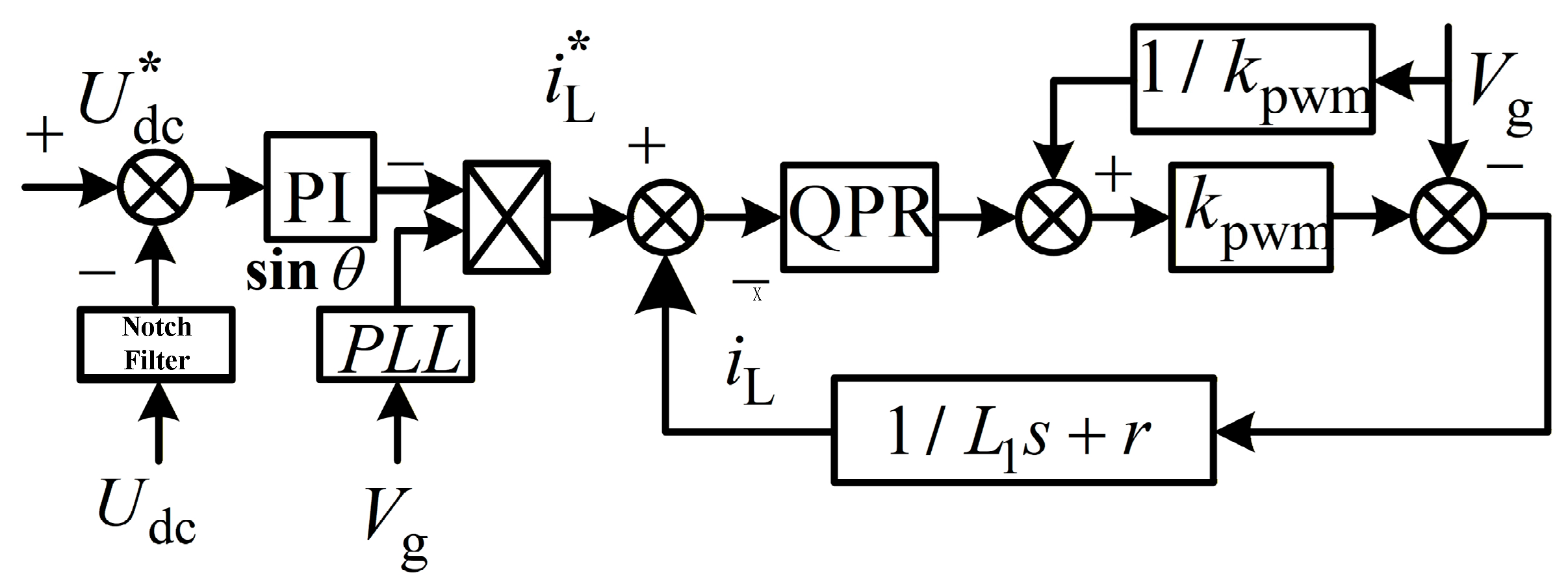
where r is the equivalent resistance of L1. The control structure shown in Figure 2 is adopted for the inverter in grid-connected mode.
A PI controller is used in the outer voltage loop to realize the static-error-free tracking of the DC bus voltage Udc to its reference value U* dc, thus maintaining the stability of the DC bus voltage. The double-frequency component contained in Udc needs to be filtered out by a notch filter. To suppress grid voltage interference, feedforward compensation of the grid voltage is added to the output of the inner loop controller. The inner current loop is required to realize the static-error-free tracking of the AC inductor current to its reference value i L * , and thus the quasi-proportional resonant (QPR) controller expressed in (3) is employed.
G QPR s = k p + 2 k r ω c s s 2 + 2 ω c s + ω 0 2
where kp is the proportional coefficient, kr the resonant coefficient, ωc the cut-off frequency, and ω0 the resonant frequency. Considering the effects of control and modulation delays, the total delay is 1.5Ts, where Ts denotes the control cycle. The delay transfer function is given in (4):
d e l a y s = 1 1 + 1.5 s T s .
Thus, the open-loop transfer function Gi(s) of the current loop is given by:
G i s = ( k p s 2 + 2 ω c k r + k p s + k p ω 0 2 ) k pwm 1.5 s T s + 1 L 1 s 3 + r + 2 ω c L 1 s 2 + ω 0 2 L 1 + 2 ω c r s + r ω 0 2
where kpwm is the equivalent gain of the inverter and ω0 = 100π. Since the allowable range of grid voltage frequency fluctuation is ±0.5 Hz, the value range of ωc is 0~π rad/s, and 3 rad/s is selectable. In addition, the cut-off frequency ωioff of the inner current loop is set to 1/10fs, and the phase margin is required to be greater than 45°, that is:
G i j ω ioff = 1 G i j ω ioff + 180 > 45
For (7), assuming that the power loss of the inverter switching devices is neglected, the power flowing into the inverter from the DC bus is equal to the inverter’s output power; thus, the following can be derived:
U dc * C 1 s U dc = U dc * i in U dc * i dc = p in 1 2 I m U m
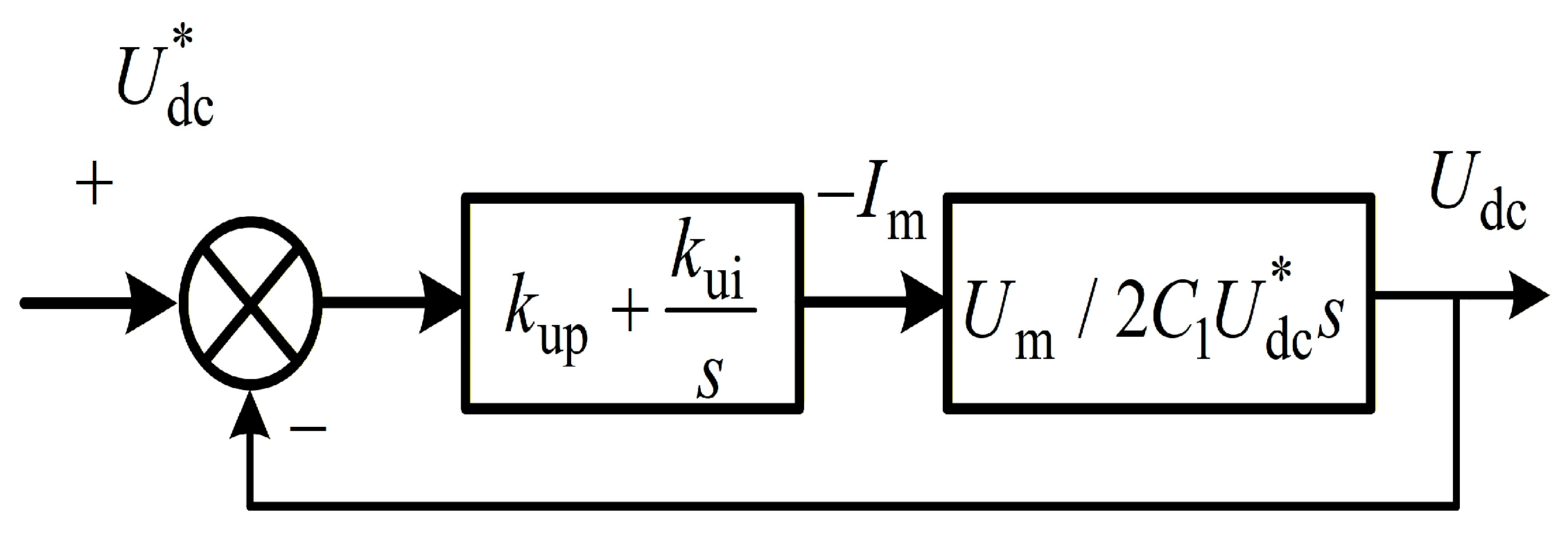
where Im and Um are the peak values of the grid current and voltage, respectively, and pin is the input power of the DC bus. Based on (7), the control structure of the outer DC bus voltage loop is shown in Figure 3.
The notch filter in (8) is used to filter out the second-order ripple in Udc where ωt = 2ω0 and η = 0.707.
G s = s 2 + ω t 2 s 2 + 2 η ω t s + ω t 2 .
The closed-loop transfer function Guc(s) of the outer DC bus voltage loop is given by:
G uc s = k up s + k ui 2 C 1 U dc * s 2 / U m + k up s + k ui .
It can be treated as a typical second-order element to configure kup and kui, thus:
k ui = 2 C 1 U dc * ω n 2 U m k up = 2 C 1 U dc * 2 ζ ω n U m
where ζ is the damping coefficient and ωn is the natural oscillation angular frequency.

2.2.2. Control in Off-Grid Mode

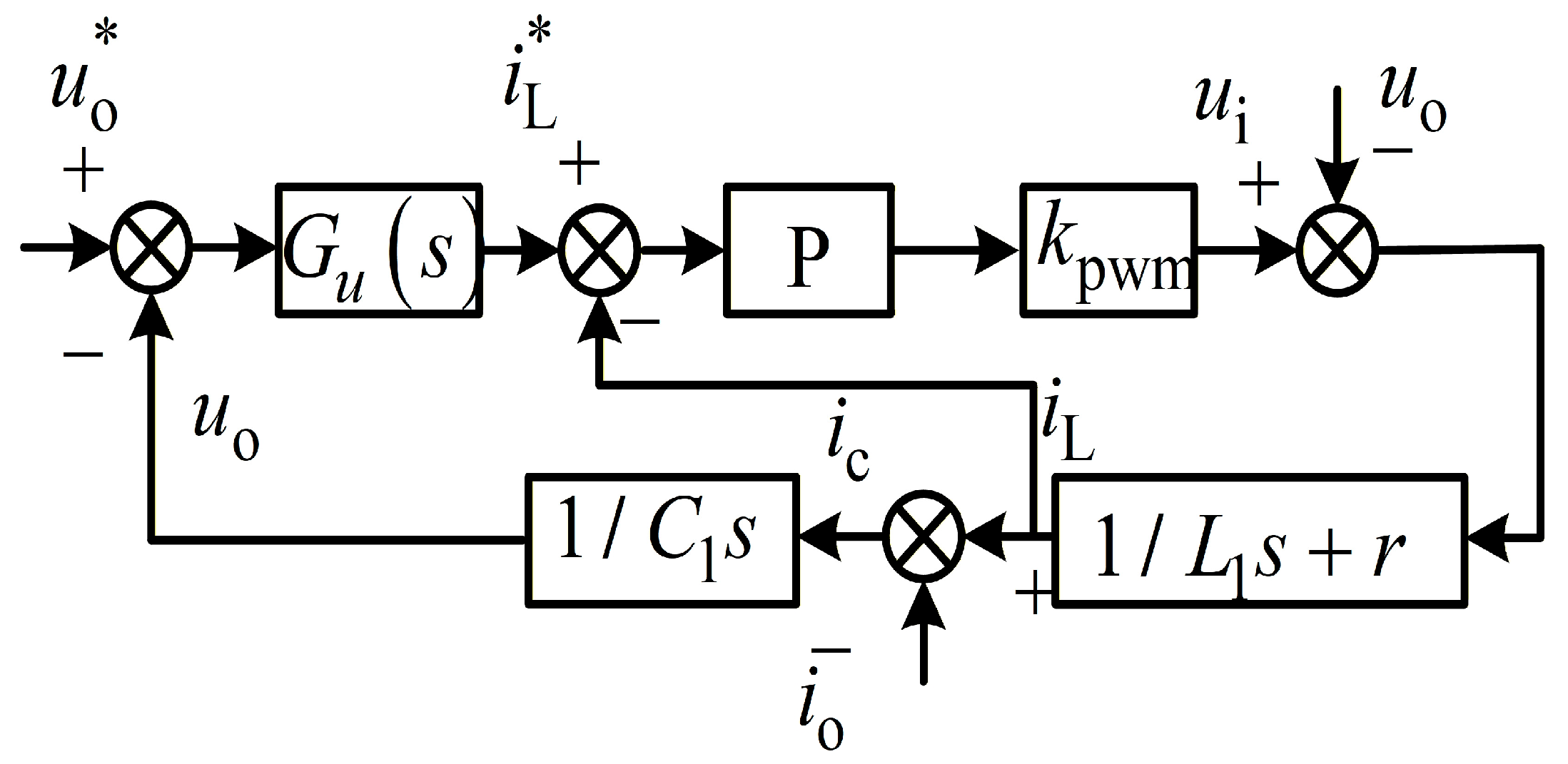
The mathematical model of the inverter in off-grid mode is given by:
u o = u i L 1 d i L d t r i L
C 2 d u o d t = i L i o
Figure 4 shows the off-grid control structure of the inverter, which adopts a dual closed-loop control strategy of voltage and current.
Proportional control is adopted for the current control of the off-grid inverter. Since the series resistance of the filter inductor is small, it is neglected. The closed-loop transfer function of the inner current loop control is given by:
G ( s ) = i L ( s ) i L * ( s ) = 1 s L 1 / ( k pi k pwm ) + 1 = 1 τ i s + 1
where τi determines the bandwidth of the system and the control parameter kpi is set as:
k pi = L τ i k pwm
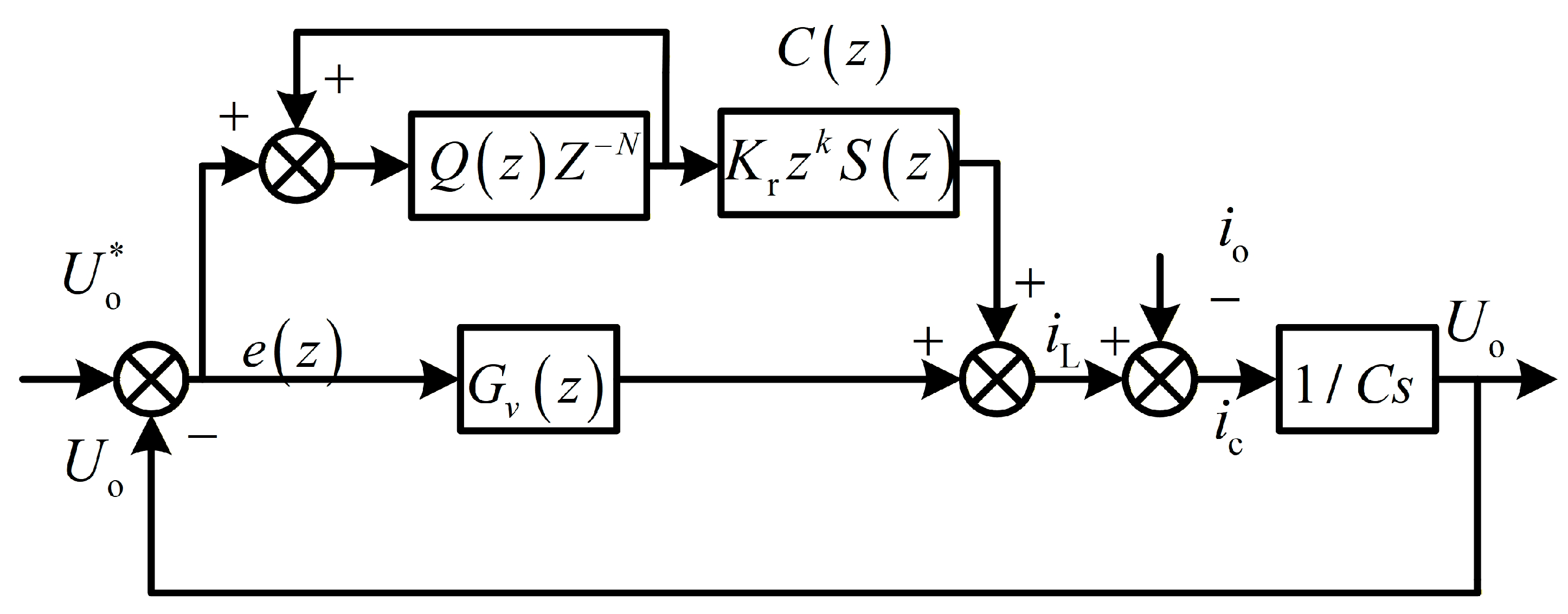
Since the inner current loop features a fast dynamic response, the closed-loop current structure can be equivalent to a unity gain. The outer voltage loop control adopts a combination of repetitive control and quasi-resonant control. The control structure of the outer voltage loop is shown in Figure 5.
Where Q(z) is the integral coefficient of the repetitive controller, C(z) is the compensator, Kr is the gain of the repetitive controller, zk is the lead element for phase compensation, and S(z) is the filter. This controller calibrates the low- and mid-frequency gain of the controlled object to 1, which eliminates the resonant peak of the controlled object. In addition, it enhances the high-frequency attenuation characteristic of the forward channel and improves the stability and anti-interference ability of the system. Gv(z) is the quasi-resonant controller.
Q(z) can be set as a low-pass filter or a constant, and a constant is usually selected with a value range of 0.95–1. The closer the value of Q(z) is to 1, the higher the steady-state accuracy, but the system may oscillate. The filter S(z) consists of a notch filter for suppressing the resonant peak of the system and a second-order filter for filtering out high-frequency noise. A comb filter expressed in (15) is adopted for the notch filter, where m is the number of delay steps.
F ( z ) = z m + a + z m 2 + a
When z = e, (15) can be turned into
F θ = 2 cos m θ + a 2 + a .
where θ = ω/fs, ω is the resonant frequency, and fs is the switching frequency.
When a = 2 and F(θ) = 0, F(z) achieves the maximum attenuation at specific frequencies with zero phase shift; thus,
cos ( m θ ) = 1 m θ = π + 2 k π   , k = 0 , 1 , 2
Let k = 0, then we have
m θ = π m = f s π / ω
The second-order filter of the filter S(z) is used to provide high-frequency attenuation characteristics, whose resonant frequency can be selected as the cut-off frequency of the inverter, and the damping coefficient is chosen to be in the range of 0.707–1. In the design of the quasi-resonant controller, the influence of the repetitive controller part can be neglected initially, which renders the system a linear one and facilitates the design process.

3. Smooth and Flexible Grid-Connected/Off-Grid Transition Control Strategy for ESS Microgrid Inverters

3.1. Grid-Connected/Off-Grid Switching Strategy for ESS Inverters

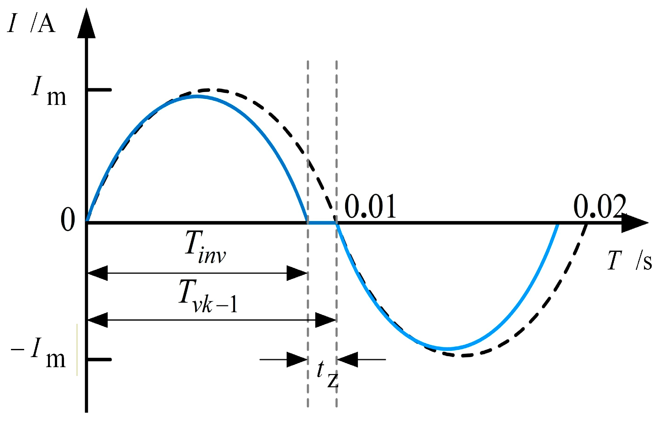
The principle of the traditional Active Frequency Drift with Positive Feedback (AFDPF) method is to inject the slightly distorted current of the inverter into the main grid. When an islanding event occurs, the frequency of the voltage at the point of common coupling (PCC) is forced to shift upward or downward. An islanding event is detected once the frequency shift exceeds the threshold value. With the AFDPF method, the slightly distorted current output by a single-phase inverter has two types of shifts: upward and downward. This paper adopts the upward shift method, as shown in Figure 6, where the light blue curve is the reference for the slightly distorted current and the black dashed line is the desired current reference.
The truncation coefficient cf is defined as follows:
c f = t z T v k 1 .
The reference frequency fi of the current with slight distortion is given by:
f i = f v k 1 1 c f
where fvk−1 is the PCC voltage frequency at the previous sampling step. The calculation formula for the truncation coefficient of the traditional AFDPF is given by:
c f = c f 0 + k f f 0
where cf0 is the initial truncation coefficient, k is the positive feedback coefficient, f is the real-time voltage frequency at the PCC, and f0 is the standard grid voltage frequency.
In practical systems, the grid voltage exhibits a certain degree of frequency fluctuation. Consequently, the positive feedback attaches the error fluctuation of the frequency deviation to the disturbance, which impairs the power quality of the grid-connected current. To address this problem, this paper improves the traditional AFDPF method and proposes a variable positive feedback coefficient method for islanding detection. This method adopts a piecewise algorithm expressed in (22), which employs a cubic power-based detection method when the frequency deviation is small and a parabola-based detection method when the frequency deviation is large. Since the frequency fluctuation range of normal grid voltage is within 0.2 Hz, the piecewise threshold is set to 0.2 Hz.
c f = c f 0 + k Δ f 3 , Δ f Δ f e ¯ c f 0 + k sign Δ f abs Δ f , Δ f > Δ f e ¯
where Δf = ff0.
This method enables a small positive feedback coefficient when the frequency deviation is small, which reduces the interference of grid voltage frequency fluctuations on islanding detection and the impact on power quality. When the frequency deviation is large, a large positive feedback coefficient is adopted to amplify the current disturbance, accelerate the frequency offset of the inverter’s output voltage, and ensure the rapid realization of islanding detection. This method can not only realize the timely and rapid response to islanding but also avoid the distortion of grid-connected current under normal grid conditions.

3.2. Non-Detection Zone Analysis of Islanding Detection Method

To evaluate the non-detection zone (NDZ) of islanding detection methods, it is necessary to reduce the dimension and complexity while accurately describing the NDZ characteristics. Therefore, the Qf0 × Cnorm space of the load parameter coordinate system is selected to characterize the NDZ distribution, which can reflect the relationship between the quality factor and the success or failure of islanding detection. The parameters are defined as follows:
Q f 0 = R ω 0 L
C n o r m = C C r e s
C r e s = 1 L ω 0 2
where R, L, and C represent the resistance, inductance, and capacitance of the local load respectively, and denotes the grid angular frequency.
According to [22], the boundary formula of the NDZ for the active frequency drift method can be expressed as
arctan Q f 0 ω 0 ( Δ ω ω 0 ) 2 + 2 Δ ω ω 0 + Δ C 1 + Δ ω ω 0 ω 0 + Δ ω 2 = π 2 c f
Here, ∆ω = ωω0, ∆C = Cnorm − 1, where C = (1 + ∆C)Cres.
Since ∆ω is negligible compared to the ω itself, (21) can be expressed as
arctan Q f 0 2 Δ ω ω 0 + Δ C = π 2 c f
Further derivation leads to the following expression:
Δ C = tan π 2 c f Q f 0 2 Δ ω ω 0
Considering that the frequency fluctuation range does not exceed 0.5 Hz, it can be obtained that
tan π 2 c f Q f 0 1 f 0 + 1 < C n o r m < tan π 2 c f Q f 0 + 1 f 0 + 1
According to (21), the non-detection zone expression of AFDPF with fixed positive feedback gain is
tan π 2 c f 0 + 0.5 π 2 k Q f 0 1 f 0 + 1 < C n o r m < tan π 2 c f 0 0.5 π 2 k Q f 0 + 1 f 0 + 1
Similarly, according to (22), the non-detection zone expression of the method proposed in this paper is obtained as follows:
tan π 2 c f 0 + 0.5 π 2 k Q f 0 1 f 0 + 1 < C n o r m < tan π 2 c f 0 0.5 π 2 k Q f 0 + 1 f 0 + 1
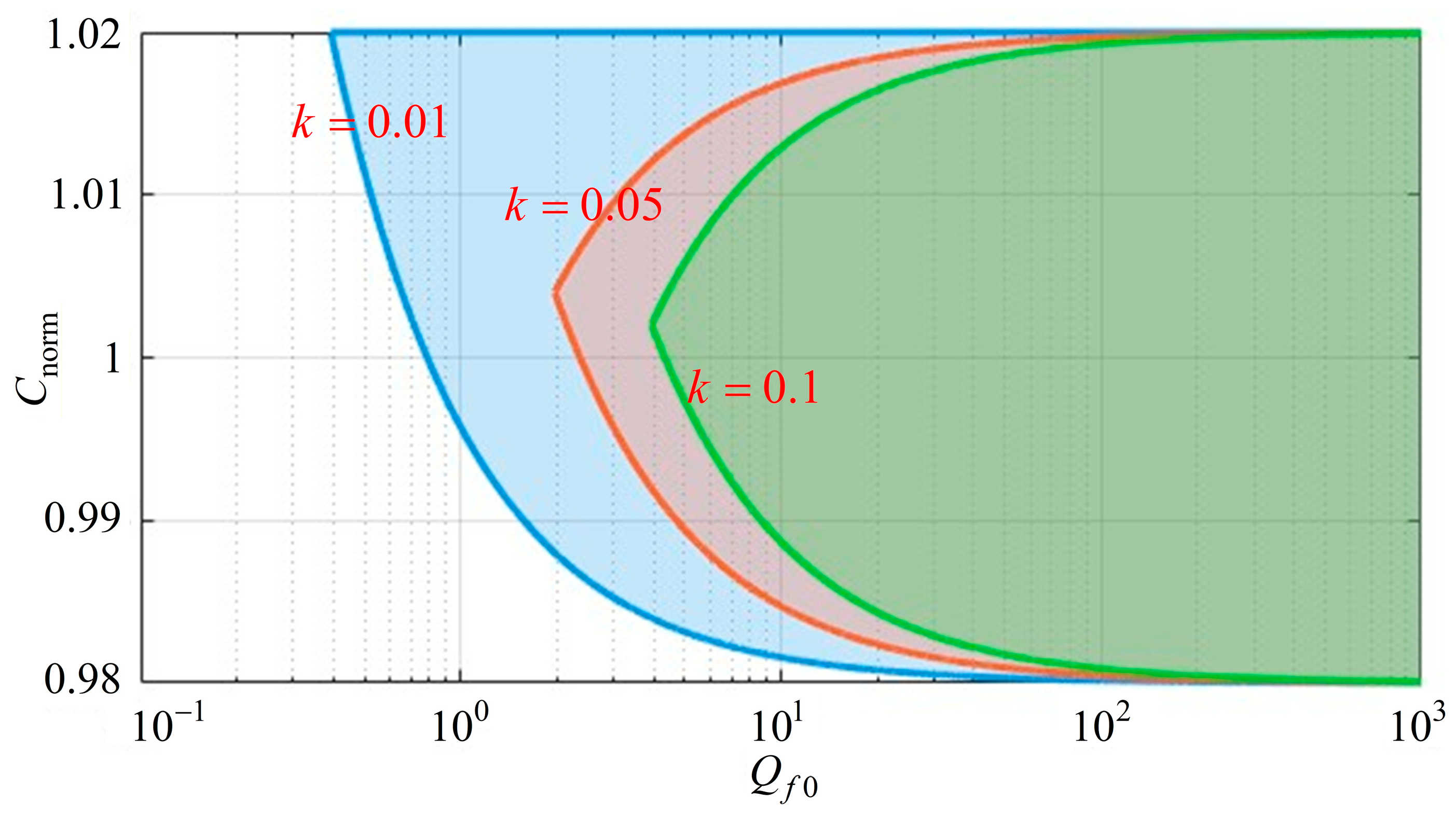
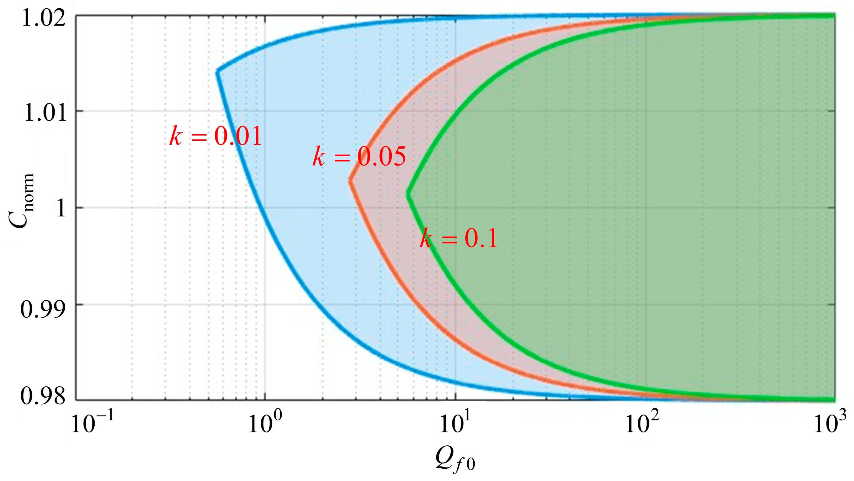
Based on the formulations in (30) and (31), the non-detection zone (NDZ) distributions of the two methods can be mapped separately with different k, and the cf0 is equal to 0.005.
As shown in Figure 7 and Figure 8, increasing the value of k helps reduce the non-detection zone. Under the same value of k, the proposed method exhibits a smaller non-detection zone than the method with fixed positive feedback gain.

4. Simulation Verification

4.1. Islanding Detection Algorithm Verification

To verify the performance of the proposed islanding detection algorithm and compare it with the conventional active frequency drift algorithm with fixed positive feedback gain, simulations are conducted under the grid condition with a short-circuit ratio (SCR) of 10 in the presence of grid frequency fluctuations. At 0.3 s, the grid frequency steps abruptly from 50 Hz to 50.1 Hz. The load is selected as the RLC type. The value of cf is set to 0.005, and the value of k is set to 0.01.
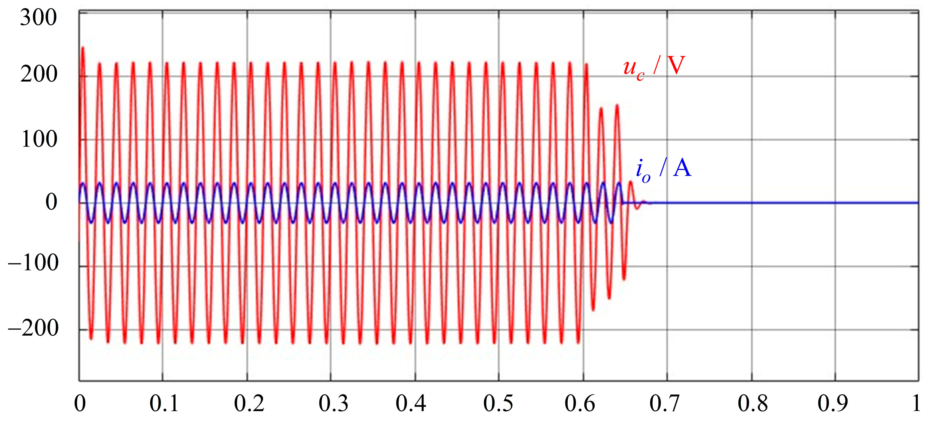
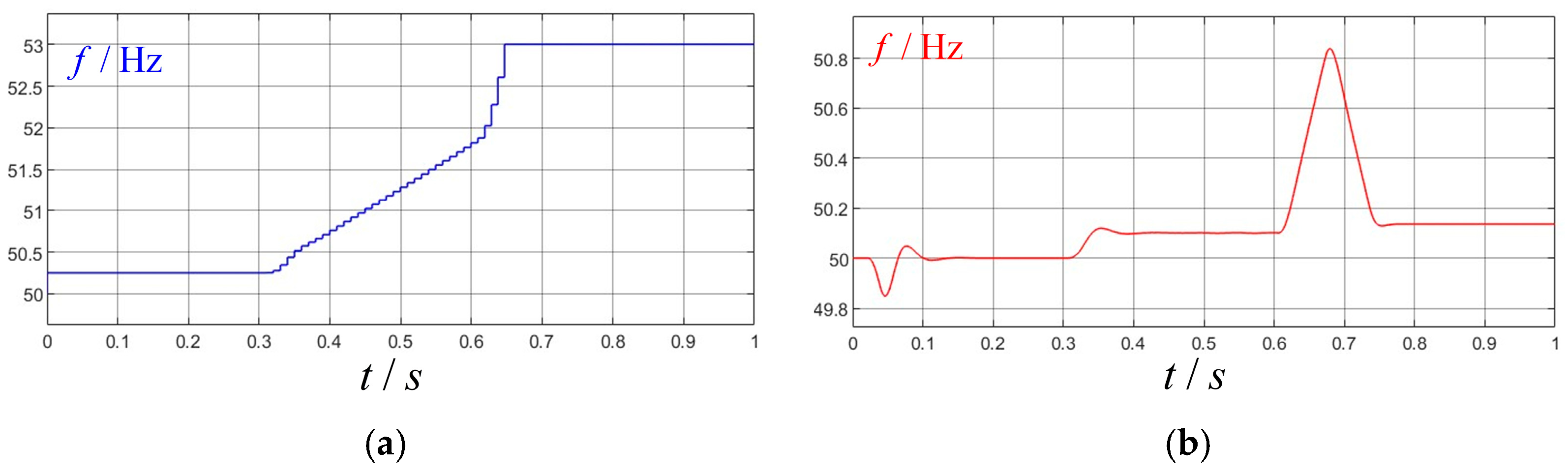
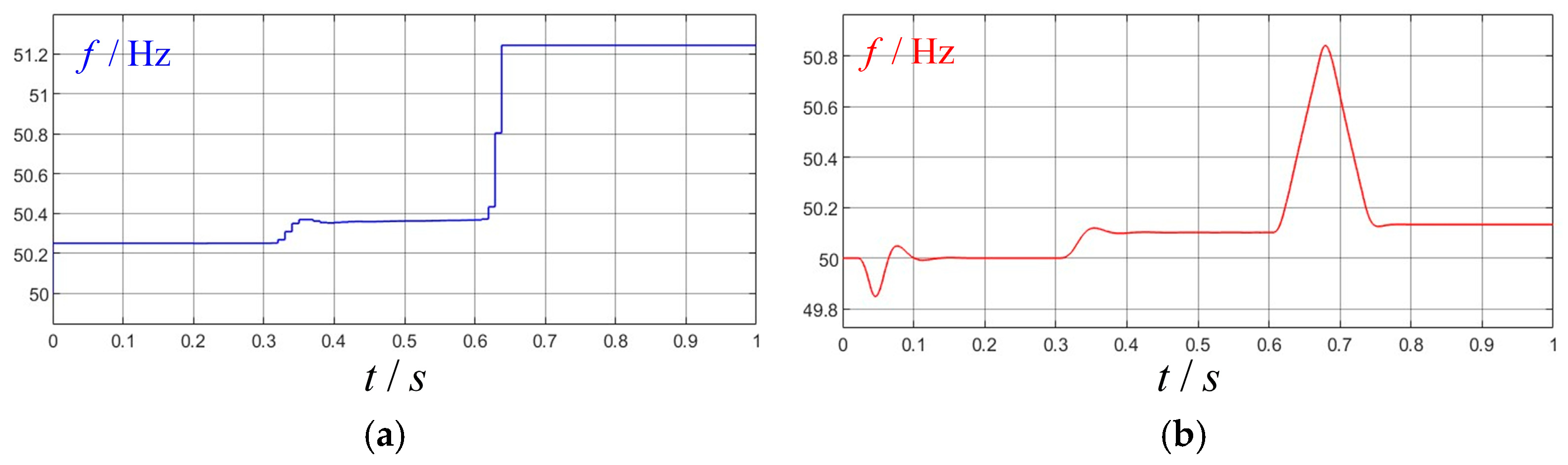
Combined with Figure 9 and Figure 10, it can be concluded that both algorithms are capable of detecting the islanding condition after its occurrence. However, comparing the injected frequency perturbations of the two algorithms after the frequency disturbance in Figure 11a and Figure 12a, it can be observed that the conventional AFDPF with fixed positive feedback gain exhibits a continuous and significant increase in the injected frequency perturbation following the frequency step. In contrast, the proposed method only shows a minor increase. This indicates that the proposed method has a certain level of immunity to normal grid frequency fluctuations. It can be observed from Figure 11b and Figure 12b that the two algorithms achieve nearly the same detection speed.
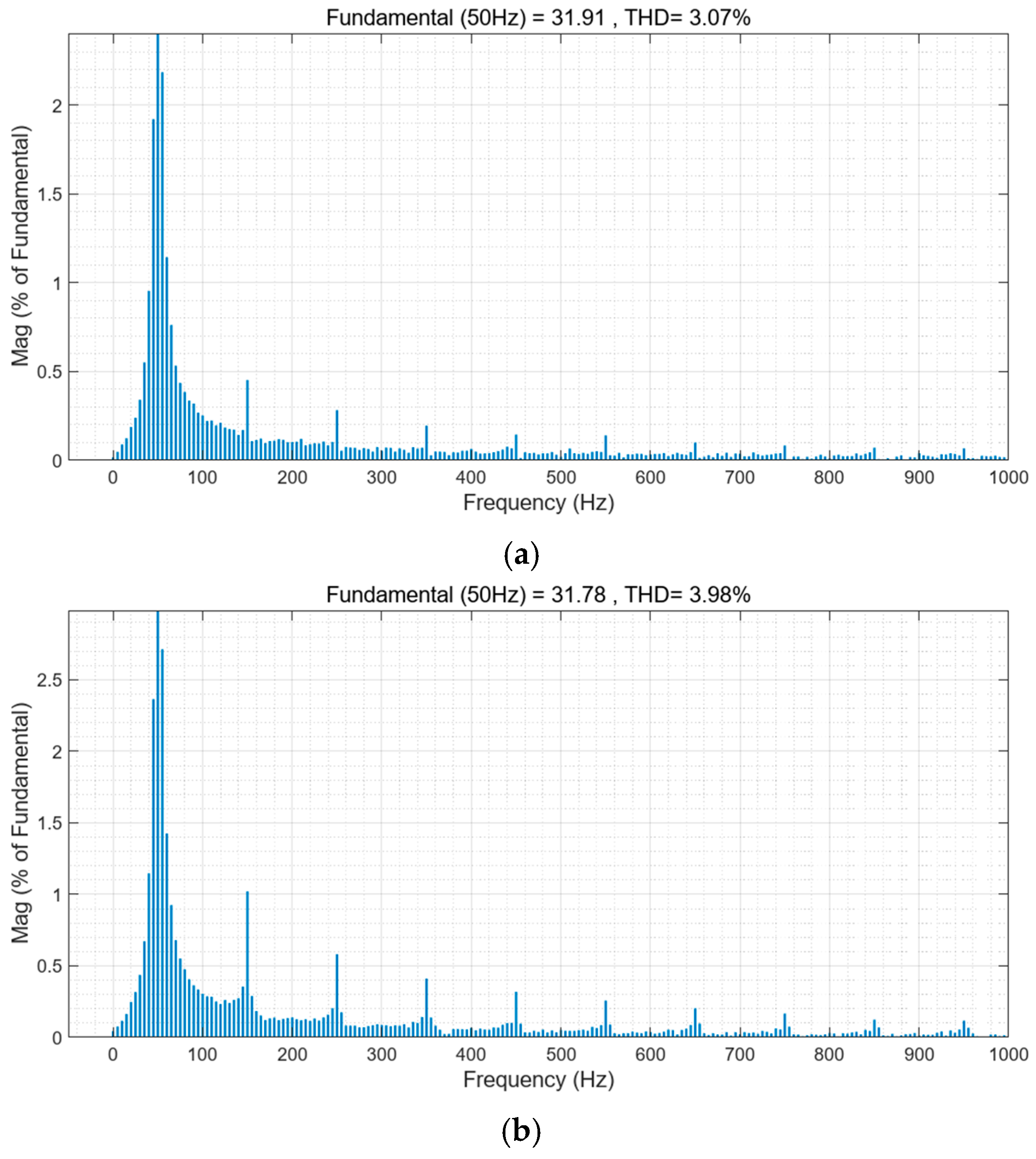
By comparing Figure 13a,b, it can be found that under normal grid-connected conditions, the grid-connected current harmonic content of the proposed method is nearly 1% lower than that of the conventional method. The proposed method effectively reduces the harmonic injection caused by islanding detection.
It can be seen from Table 1 that the proposed method possesses obvious advantages over the conventional method, especially in terms of the non-detection zone and harmonic performance.

4.2. Inverter Control in Off-Grid Mode

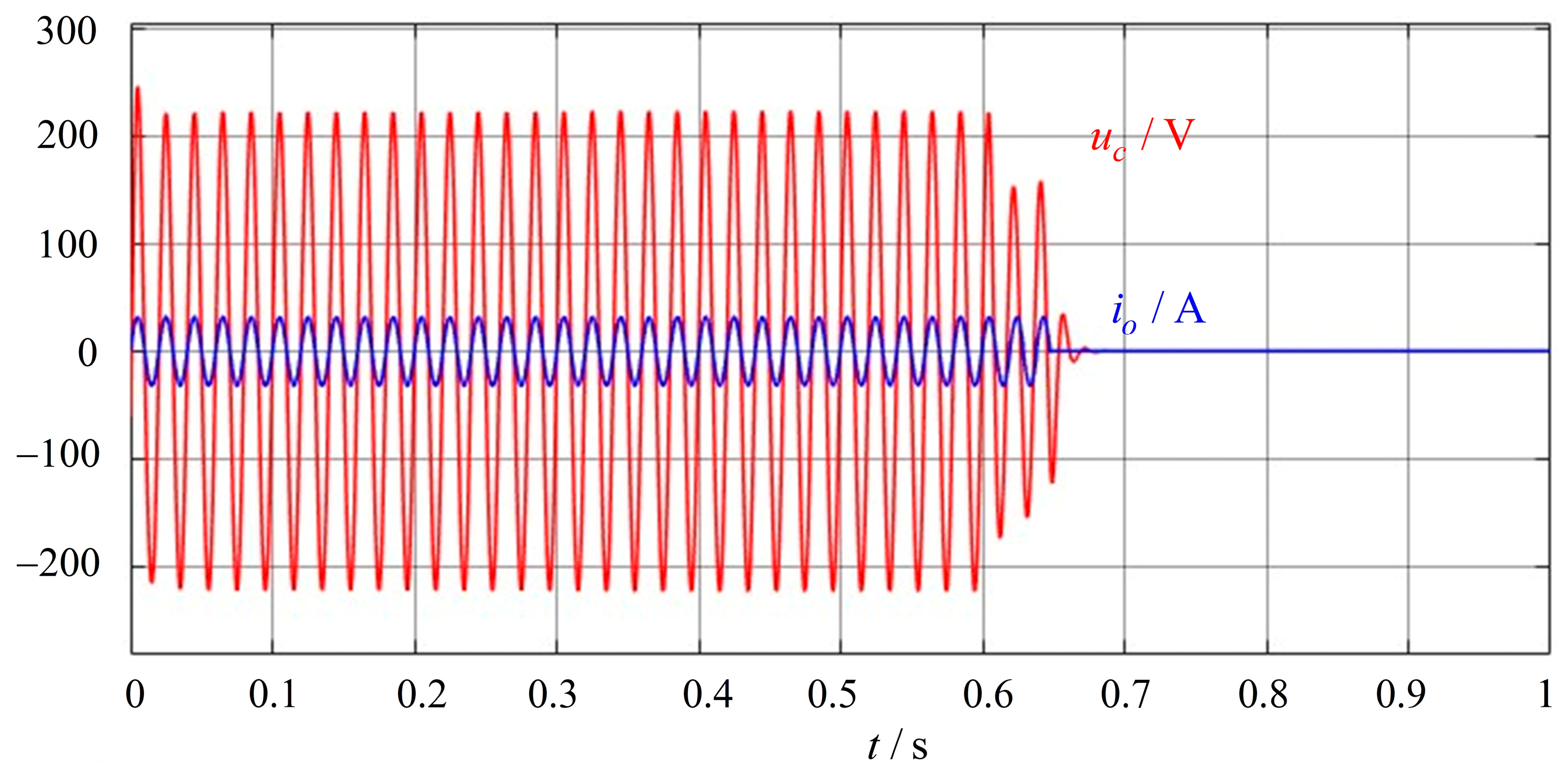
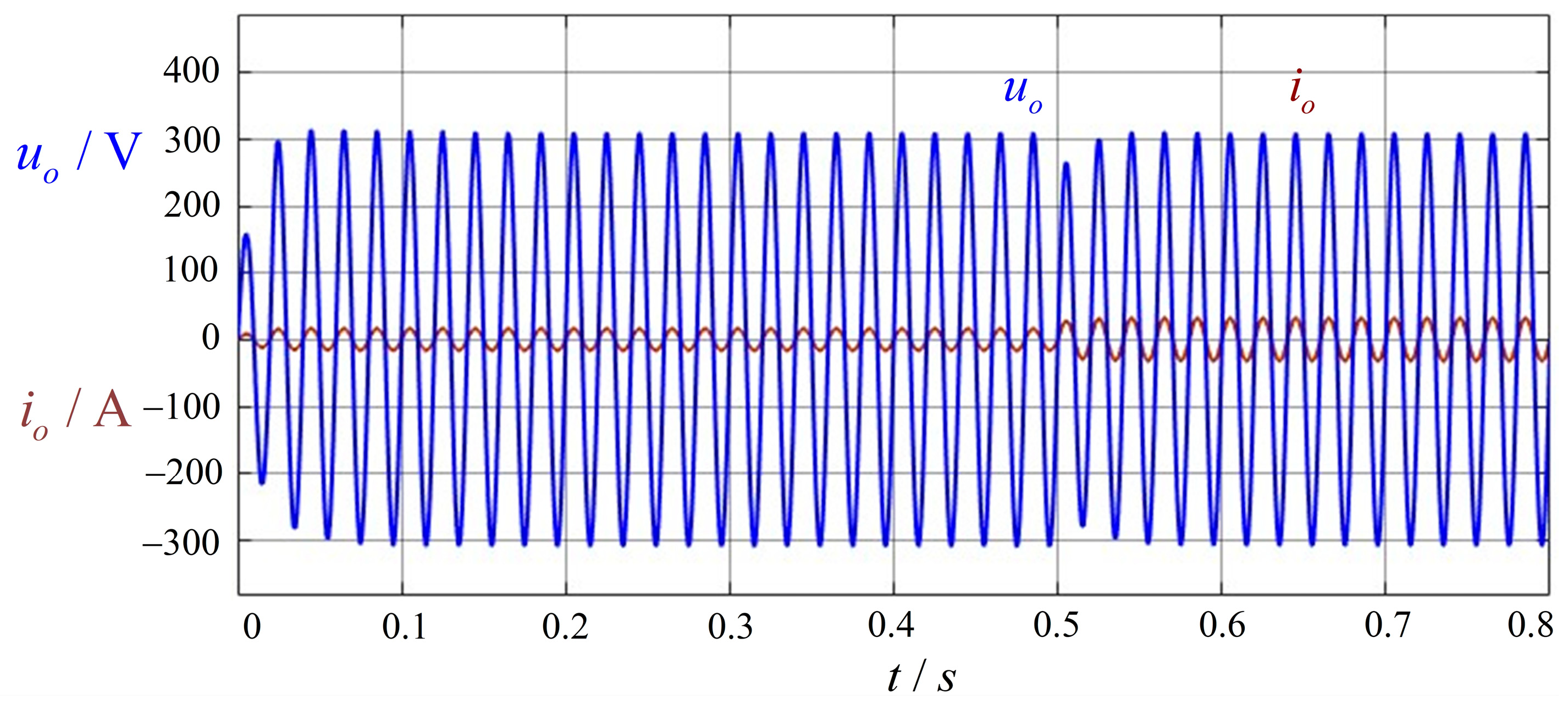
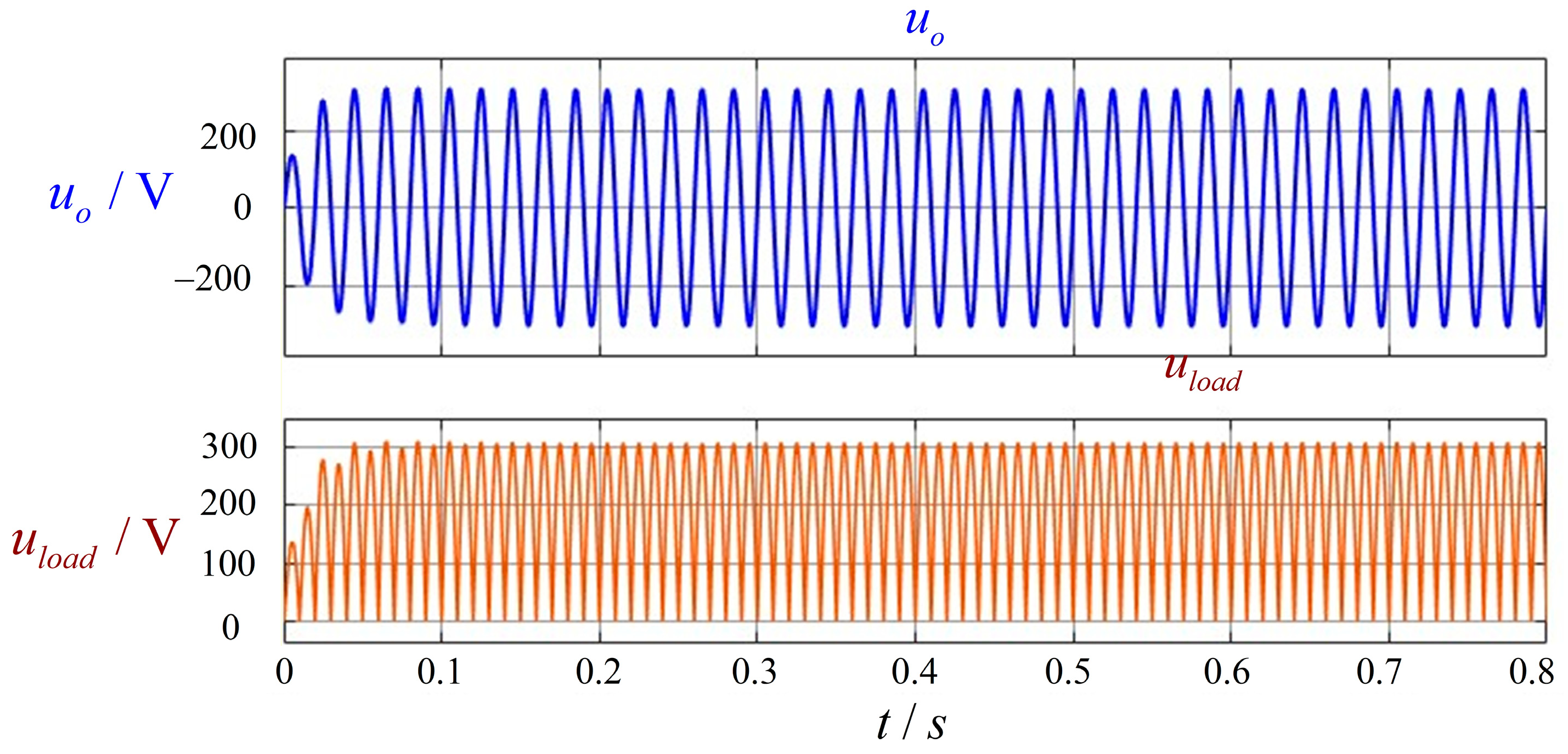
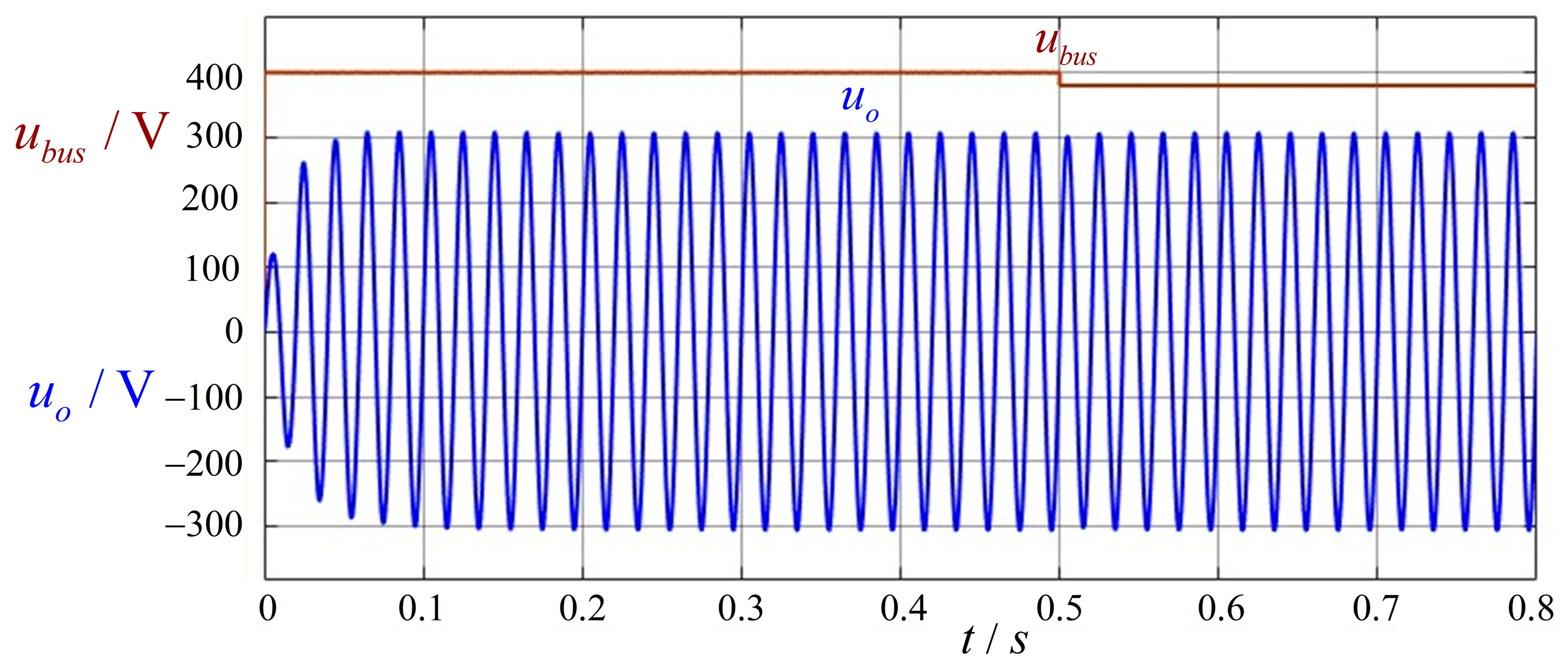
To verify the anti-disturbance capability and dynamic response performance of the proposed control strategy in the off-grid mode, simulations are carried out under the working conditions of sudden load switching, nonlinear load access, and DC bus voltage fluctuation.
Figure 14 shows the inverter output waveforms when the load suddenly increases from 2500 W to 5000 W. It indicates that the inverter can quickly adapt to load variations and maintain a stable output voltage even under sudden load step changes. Figure 15 presents the operating performance of the inverter under nonlinear load conditions. In this paper, an uncontrolled rectifier bridge is adopted as the nonlinear load. It can be seen that the output voltage of the inverter is smooth with a low distortion rate. Figure 16 indicates that even when the DC bus voltage suddenly drops by 40 V, it has only a slight impact on the output voltage of the inverter. In addition, io, uo, and uload represent the output current of the inverter, the output voltage of the inverter, and the voltage across the resistive load on the output side of the uncontrolled rectifier, respectively.
According to the above simulation results, the controller in off-grid mode can well adapt to various disturbances and exhibits excellent anti-disturbance capability and dynamic response performance.

5. Experimental Verification

Based on a self-developed single-phase ESS microgrid inverter, the proposed grid-connected/off-grid dual-mode control and switching strategy is verified and analyzed. Table 1 presents the main parameters of the system. In the experiment, the inverter adopts SPWM modulation. The energy storage side is simulated by a DC power supply (IT6018C-1500-30, ITECH Electronics Co., Ltd., Nanjing, Jiangsu, China), and the controller is implemented based on the DSP chip TMS320F28069. A resistive load is adopted on the test platform. The nominal accuracy of the current sensor and the voltage sampling circuit are ±0.95% and 0.5%. The main parameters of the system are listed in Table 2.

5.1. Grid-Connected Mode Operation

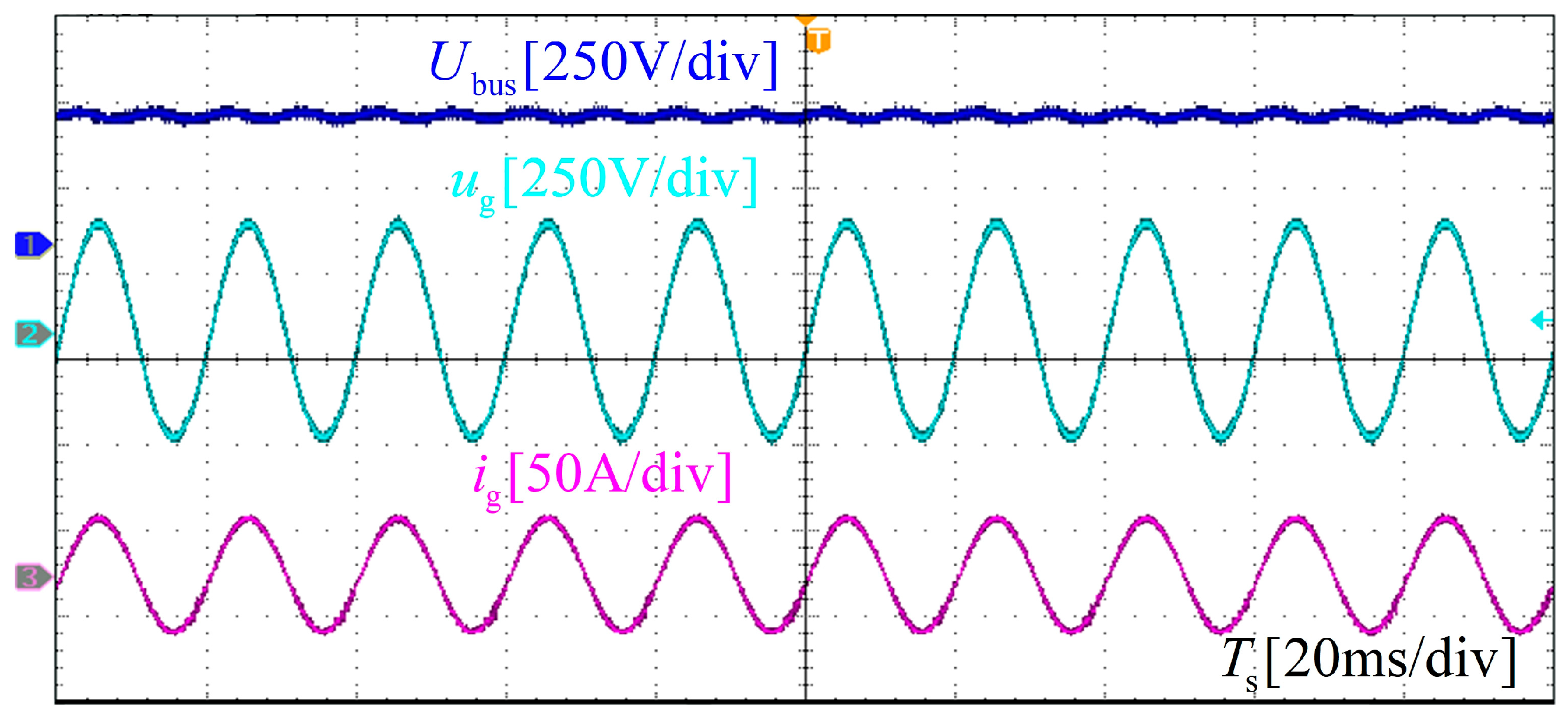
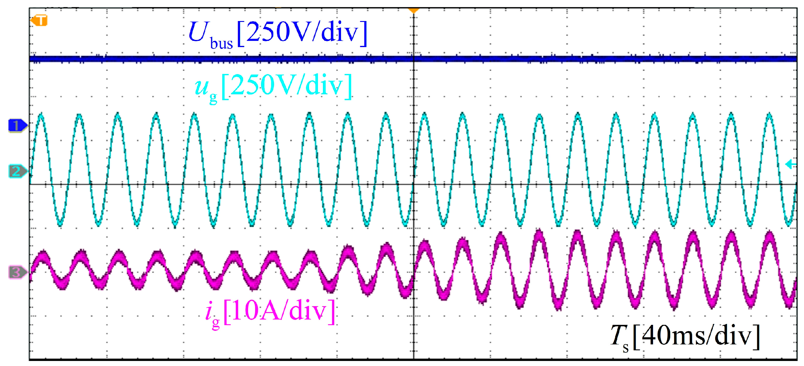
In the grid-connected mode, the grid-connected waveforms of the ESS inverter are presented in Figure 17. It can be observed that the inverter operates in the unity power factor mode with a stable system performance. The grid-connected current waveforms are smooth with low harmonic content, yielding high power quality. In addition, reference power adjustment tests under grid-connected mode were conducted. As can be seen from Figure 18, the grid-connected current varies smoothly without sudden changes.

5.2. Off-Grid Mode Operation

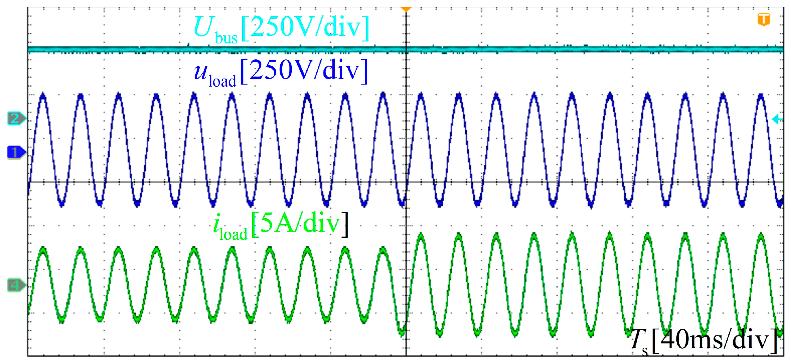
In off-grid mode, a resistive load is applied, and the corresponding operating waveforms are shown in Figure 19. It can be observed that the load voltage uload and load current iload are distortion-free with low harmonic content and maintain the same phase. In addition, Figure 19 also shows the loading test under off-grid mode. There is no current impact during the loading process, and the test proceeds very smoothly.

5.3. Flexible Grid-Connected/Off-Grid Mode Switching

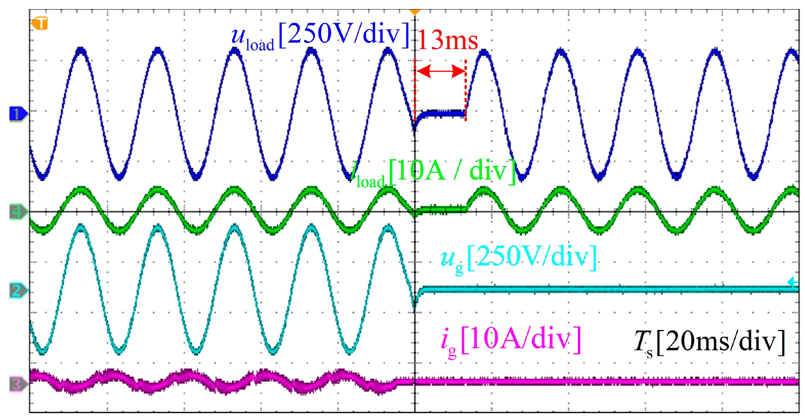
This paper verifies the operation performance of the energy storage system (ESS) inverter during the grid-connected to off-grid switching process. The grid-connected/off-grid switching waveforms shown in Figure 20 demonstrate that the inverter can rapidly detect the occurrence of islanding under grid faults and initiate the grid-connected to off-grid switching, with no voltage or current overshoot during the entire process. The time from grid-connected shutdown to off-grid startup is 13 ms. Due to the adoption of the active frequency drift method, voltage and current distortion appear during the grid-connected to off-grid transition. However, the fast transient switching does not affect the normal operation of the inverter.

6. Conclusions

This paper designs corresponding control strategies for the grid-connected and off-grid modes of the inverter in energy storage microgrids, and proposes an improved mode switching algorithm. Simulation results demonstrate that the improved AFDPF strategy proposed in this paper has a smaller non-detection zone and lower current THD compared with the conventional AFDPF strategy, while its detection speed is not inferior to that of the traditional method with fixed positive feedback gain. Experimental results show that the energy storage inverter can operate stably in both grid-connected and off-grid modes, and the grid-connected/off-grid switching process is accurate and rapid, which verifies the effectiveness of the proposed control and flexible mode switching strategies for energy storage inverters. However, the applicability of the proposed method in multi-inverter scenarios has not been accurately verified yet. Further research is needed to improve the algorithm by considering the effect of the dilution effect in multi-inverter applications.

Author Contributions

Conceptualization, J.Z., K.Z. and X.H.; methodology, J.Z. and H.T.; writing—original draft preparation, J.Z., Y.Z. and K.Z.; writing—review and editing, X.H. and M.S. All authors have read and agreed to the published version of the manuscript.

Funding

This work is supported by Hunan Provincial Science and Technology Major Project under Grant 2025QK1004, and State Grid Corporation Laboratory of Intelligent Application Technology for Distribution Network.

Data Availability Statement

The original contributions presented in the study are included in the paper. Further inquiries can be directed to the corresponding author.

Conflicts of Interest

The authors declare no conflicts of interest.

References

  1. Min, Y.; Lei, Z.; Chen, L.; Xu, F.; Zhao, B.; Lu, Z.; Hao, L. Frequency-fixed grid-forming control for less-dynamic and safer renewable power systems. iEnergy 2024, 4, 219–234. [Google Scholar] [CrossRef]
  2. Hassan, Q.; Viktor, P.; Al-Musawi, T.J.; Mahmood Ali, B.; Algburi, S.; Alzoubi, H.M.; Khudhair Al-Jiboory, A.; Zuhair Sameen, A.; Salman, H.M.; Jaszczur, M. The renewable energy role in the global energy Transformations. Renew. Energy Focus 2024, 48, 100545. [Google Scholar] [CrossRef]
  3. Wei, X.; Yue, D.; Hancke, G.P.; Dou, C.; Li, H.; Qiu, Y. Ultra Short-Term Solar Irradiance Forecast Based on Multimodal Data Fusion and Fuzzification. IEEE Trans. Ind. Inform. 2025, 21, 3256–3265. [Google Scholar] [CrossRef]
  4. Xue, C.; Wang, J.; Li, Y. Model Predictive Control for Grid-Tied Multi-Port System with Integrated PV and Battery Storage. IEEE Trans. Smart Grid 2022, 13, 4596–4609. [Google Scholar] [CrossRef]
  5. Yuan, H.; Yue, W.; Dou, C.; Hancke, G.P.; Zhang, Z.; Wei, X.; Li, H.; Guo, Y. Aggregated Distributed Photovoltaics-Based Active Fast Power-Frequency Regulation in the New Power System. IEEE Trans. Sustain. Energy 2026, 17, 1728–1740. [Google Scholar] [CrossRef]
  6. Alam, M.J.E.; Muttaqi, K.M.; Sutanto, D. A Novel Approach for Ramp-Rate Control of Solar PV Using Energy Storage to Mitigate Output Fluctuations Caused by Cloud Passing. IEEE Trans. Energy Convers. 2014, 29, 507–518. [Google Scholar] [CrossRef]
  7. Li, S.; Zhou, S.; Li, H. Harmonic Suppression Strategy of LCL Grid-Connected PV Inverter Based on Adaptive QPR_PC Control. Electronics 2023, 12, 2282. [Google Scholar] [CrossRef]
  8. Lu, W.; Wang, W.; Zhou, K.; Fan, Q. General High-Order Selective Harmonic Repetitive Control for PWM Converters. IEEE J. Emerg. Sel. Top. Power Electron. 2022, 10, 1178–1191. [Google Scholar] [CrossRef]
  9. Zhao, Q.; Li, S.; Li, Y.; Li, X.; Xia, Y. A Novel Repetitive Control Scheme for Grid-Tied Inverters in Consumer Electronics. IEEE Trans. Consum. Electron. 2026, 72, 159–169. [Google Scholar] [CrossRef]
  10. Aslani, F.; Li, S. Islanding Detection Methods and Challenges for Distribution Generation: A Technological Review. IEEE Access 2025, 13, 133568–133595. [Google Scholar] [CrossRef]
  11. Lashin, A.; Ghanem, A.; Kaddah, S.S.; Hu, W.; Deng, F.; Abulanwar, S. Adaptive Multimode Droop-Based Distributed Energy Management for Standalone Hybrid AC/DC Microgrid. Chin. J. Electr. Eng. 2025, 11, 146–166. [Google Scholar] [CrossRef]
  12. Liu, N.; Diduch, C.; Chang, L.; Su, J. A Reference Impedance-Based Passive Islanding Detection Method for Inverter-Based Distributed Generation System. IEEE J. Emerg. Sel. Top. Power Electron. 2015, 3, 1205–1217. [Google Scholar] [CrossRef]
  13. Reddy, V.R.; Sreeraj, E.S. A Feedback-Based Passive Islanding Detection Technique for One-Cycle-Controlled Single-Phase Inverter Used in Photovoltaic Systems. IEEE Trans. Ind. Electron. 2020, 67, 6541–6549. [Google Scholar] [CrossRef]
  14. Song, G.; Cao, B.; Chang, L. A Passive Islanding Detection Method for Distribution Power Systems with Multiple Inverters. IEEE J. Emerg. Sel. Top. Power Electron. 2022, 10, 5727–5737. [Google Scholar] [CrossRef]
  15. Liu, N.; Aljankawey, A.; Diduch, C.; Chang, L.; Su, J. Passive Islanding Detection Approach Based on Tracking the Frequency-Dependent Impedance Change. IEEE Trans. Power Deliv. 2015, 30, 2570–2580. [Google Scholar] [CrossRef]
  16. Jia, K.; Wei, H.; Bi, T.; Thomas, D.W.P.; Sumner, M. An Islanding Detection Method for Multi-DG Systems Based on High-Frequency Impedance Estimation. IEEE Trans. Sustain. Energy 2017, 8, 74–83. [Google Scholar] [CrossRef]
  17. Ganivada, P.K.; Jena, P. Frequency Disturbance Triggered D-Axis Current Injection Scheme for Islanding Detection. IEEE Trans. Smart Grid 2020, 11, 4587–4603. [Google Scholar] [CrossRef]
  18. Seyedi, M.; Taher, S.A.; Ganji, B.; Guerrero, J. A Hybrid Islanding Detection Method Based on the Rates of Changes in Voltage and Active Power for the Multi-Inverter Systems. IEEE Trans. Smart Grid 2021, 12, 2800–2811. [Google Scholar] [CrossRef]
  19. Kim, H.J.; Kim, M.S.; Lee, E.S. Enhanced Islanding Detection for GFM and GFL Inverters Using Negative Sequence Current Injection. IEEE Trans. Ind. Electron. 2025, 72, 10119–10129. [Google Scholar] [CrossRef]
  20. Wen, B.; Boroyevich, D.; Burgos, R.; Shen, Z.; Mattavelli, P. Impedance-Based Analysis of Active Frequency Drift Islanding Detection for Grid-Tied Inverter System. IEEE Trans. Ind. Appl. 2016, 52, 332–341. [Google Scholar] [CrossRef]
  21. Gupta, P.; Bhatia, R.S.; Jain, D.K. Average Absolute Frequency Deviation Value Based Active Islanding Detection Technique. IEEE Trans. Smart Grid 2015, 6, 26–35. [Google Scholar] [CrossRef]
  22. Wang, H.; Liu, F.; Kang, Y.; Chen, J.; Wei, X. Experimental Investigation on Non Detection Zones of Active Frequency Drift Method for Anti-islanding. In Proceedings of the IECON 2007—33rd Annual Conference of the IEEE Industrial Electronics Society, 5–8 November 2007; IEEE: Piscataway, NJ, USA, 2007; pp. 1708–1713. [Google Scholar]
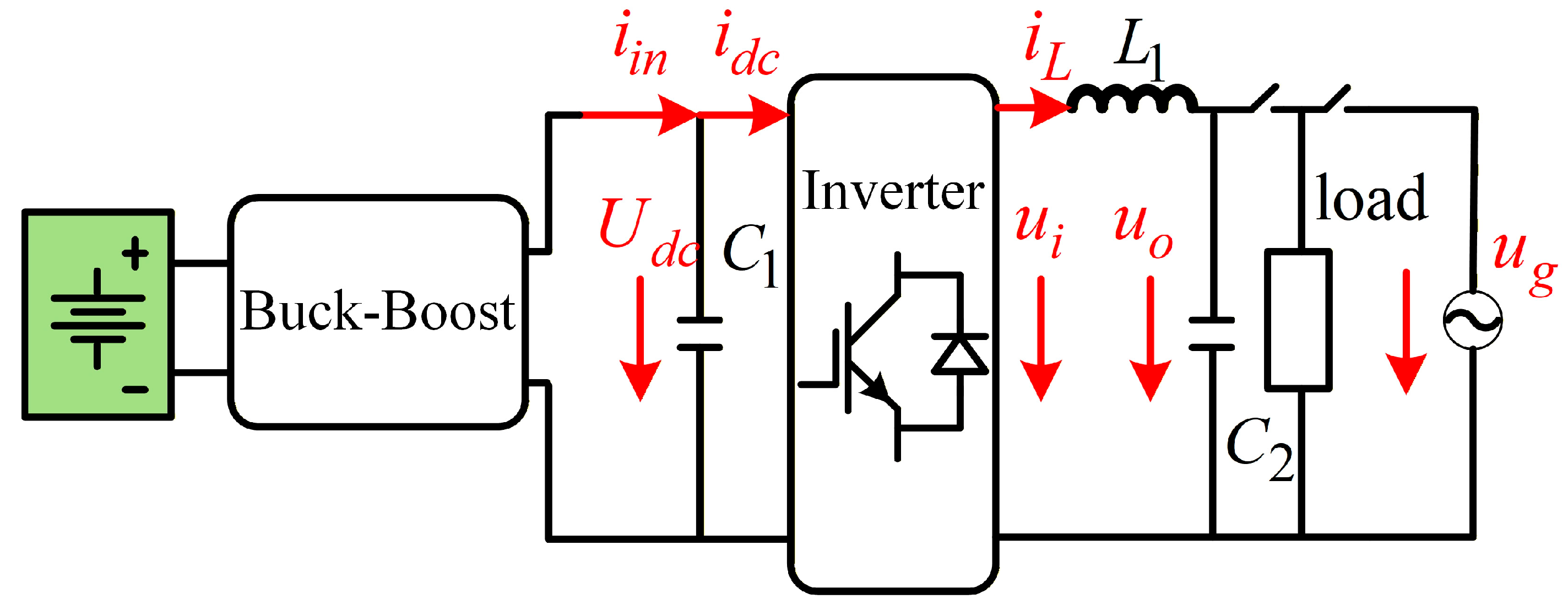
Figure 1. The ESS inverter system.
Electronics 15 02354 g001
Figure 2. Grid-connected control structure of the inverter.
Electronics 15 02354 g002
Figure 3. DC bus voltage outer-loop control structure.
Electronics 15 02354 g003
Figure 4. Off-grid control structure of the inverter.
Electronics 15 02354 g004
Figure 5. Off-grid voltage outer loop control structure of the inverter.
Electronics 15 02354 g005
Figure 6. Reference current waveform of AFDPF.
Electronics 15 02354 g006
Figure 7. NDZ distribution of AFDPF with fixed positive feedback gain.
Electronics 15 02354 g007
Figure 8. NDZ distribution of the proposed improved AFDPF.
Electronics 15 02354 g008
Figure 9. Inverter output waveforms of the proposed improved AFDPF.
Electronics 15 02354 g009
Figure 10. Inverter output waveforms of the AFDPF with fixed positive feedback gain.
Electronics 15 02354 g010
Figure 11. Value of (a) the injected frequency and (b) the actual frequency with proposed improved AFDPF.
Electronics 15 02354 g011
Figure 12. Value of (a) the proposed injected frequency and (b) the actual frequency of AFDPF with fixed positive feedback gain.
Electronics 15 02354 g012
Figure 13. THD of io under (a) the proposed improved AFDPF, (b) AFDPF with fixed positive feedback gain.
Electronics 15 02354 g013
Figure 14. Off-grid waveforms of the inverter under sudden load step.
Electronics 15 02354 g014
Figure 15. Off-Grid waveforms of the inverter under nonlinear load.
Electronics 15 02354 g015
Figure 16. Off-Grid waveforms of the inverter under bus voltage sag disturbance.
Electronics 15 02354 g016
Figure 17. Grid-connected waveforms of the inverter.
Electronics 15 02354 g017
Figure 18. Grid-connected waveforms with increased power reference.
Electronics 15 02354 g018
Figure 19. Off-grid waveforms of the inverter.
Electronics 15 02354 g019
Figure 20. The grid-connected to off-grid switching waveforms.
Electronics 15 02354 g020
Table 1. Comparison of the two methods.
Comparison CategoryTraditional AFDPFProposed AFDPF
THD of current3.98%3.07%
NDZlargersmaller
Detection time47 ms45 ms
Table 2. Main parameters of the system.
ParameterValue
AC filter inductor/mH1.12
AC filter capacitor/μF4.7
DC bus capacitor/μF2250
DC bus voltage/V380
Grid voltage (RMS)/V220
Rated power/W5000
Sampling frequency/kHz20
Switching frequency/kHz20
Dead   time / μ s 1.2
Disclaimer/Publisher’s Note: The statements, opinions and data contained in all publications are solely those of the individual author(s) and contributor(s) and not of MDPI and/or the editor(s). MDPI and/or the editor(s) disclaim responsibility for any injury to people or property resulting from any ideas, methods, instructions or products referred to in the content.