1. Introduction
The usage of diesel generators for power supply in remote areas isolated from the electrical network is widespread. However, working with these units entails a series of drawbacks, such as the need to transport the generator to its location. Additionally, fuel needs to be transported to the machine and maintenance further escalates the price of the generated kWh. In most cases the use of generators with renewable energies, such as solar and photovoltaic, is already a common solution.
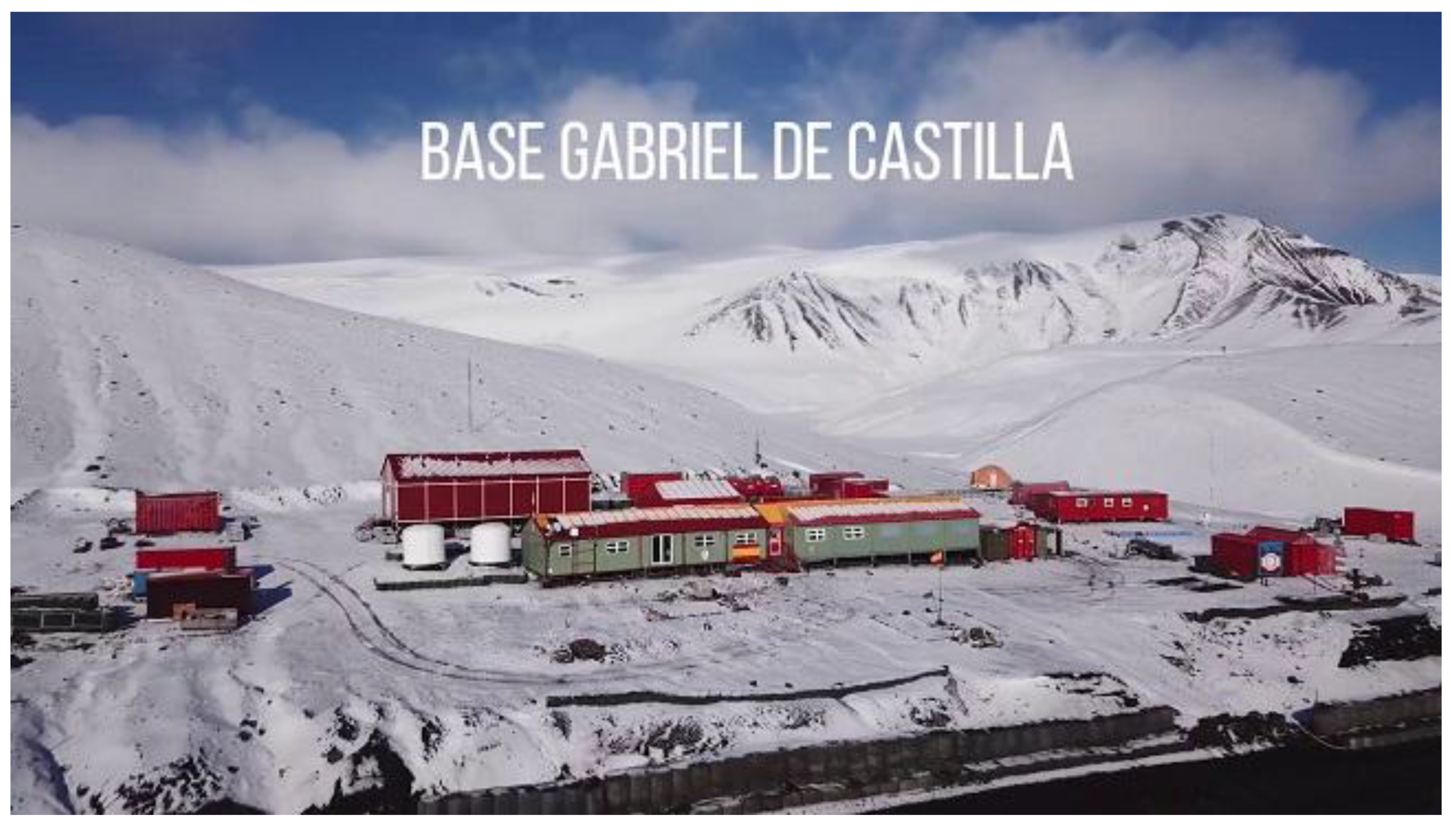
However, there are still locations in which the use of renewable energies is not an acceptable solution, such as scientific facilities in polar areas where there are not many available alternatives that meet the requirements, both technical and economic ones, to ensure energy supply. Therefore, provided that machines with efficient operation are available which minimize carbon footprint and result in significant savings in fuel, their use will be facilitated, having the added value of properly respecting the environment where these machines are installed (
Figure 1).
In this article, we introduce a machine that works efficiently, achieving significant fuel savings compared to a standard one with similar characteristics, while also considerably reducing its weight. As an example of application, we present the case study of the Spanish Antarctic Base (SAB) “Gabriel de Castilla”.
2. State of the Art
Different technologies can be used today to supply energy-isolated environments and enclaves away from the conventional electrical network, with the minimum possible impact on the environment. Depending on the amount of energy demanded and resources and location of the area, different generation techniques can be used: photovoltaic, wind and geothermal.
Hybrid architectures are also used, in which different technologies coordinated by supervisory systems are increasingly efficient [
1,
2,
3,
4]. However, in the vast majority of them, the thermal generator, normally diesel, is always present today due to the reliability of supply, as well as the generation capacity, as they cannot be supplied only with renewable energy.
2.1. Photovoltaic Generation
In the technological evolution witnessed during the past century, renewable energy sources such as photovoltaic have been affected; this is evident in the increased efficiency of photovoltaic solar panels, currently up to 24% compared to a mere 12% in the early years of this century [
5]. Likewise, researchers have developed techniques for the preliminary evaluation of a given installation [
6], even for the early detection of failures in the components of insulation, such as the board itself, insulation errors, etc. [
7,
8], thus ensuring efficient and reliable operation.
In places like the polar circles, where solar radiation is nearly parallel to the ground, these installations have low efficiency, coupled with almost six months of total darkness each year and the possibility of the panels becoming covered by snow, reducing their performance even more. Consequently, they are only viable for small devices with minimal electrical consumption or as a supplementary system in an installation based on conventional diesel generators.
Given the aforementioned factors, although photovoltaic energy is a genuine global alternative, there are regions where its installation is not feasible as the only source of energy.
2.2. Wind Power Generation
Wind energy is currently a mature technology with steady installed capacity. However, these places where the machines are located, as well the environment itself, can make the installation of a wind turbine unfeasible.
In the case of the Antarctic polar region, south of the polar circle, where its climatic conditions are extreme (with temperatures reaching around −30 °C in Winter), this cold freezes the machine’s orientation system, and additionally, there are strong gusts of wind, remnants of katabatic winds that change direction abruptly, and which expose the wind turbine to extreme aerodynamic stress. Moreover, suspended volcanic dust (if present), known as pyroclast, has a highly abrasive effect on any surface it comes into contact with, particularly degrading the turbine blades, so they become almost unusable after an Antarctic winter. For this reason, the design of these is fundamental in these environments [
9].
Due to these circumstances, the installation of vertical axis machines has been considered. Although their efficiency is somewhat lower than horizontal axis turbines, for areas with the mentioned characteristics, they can be a viable option as support for conventional generator sets.
2.3. Traditional Diesel Generation
The evolution of diesel machines has gone hand in hand with advances in both the material science and the manufacturing methods and processes.
Since the coming into force of the European Emission Regulations for Machinery, in 2019, called Stage V, the importance of fuel savings and operation improvements of the generator sets (GSs) has been shown [
10,
11,
12,
13].
Likewise, the electrical machines associated with generators have evolved, that is, the alternators, both synchronous and asynchronous, as well as the equipment used to control the machines, including their remote monitoring [
13,
14].
All of this has enabled increasingly more efficient use of these machines.
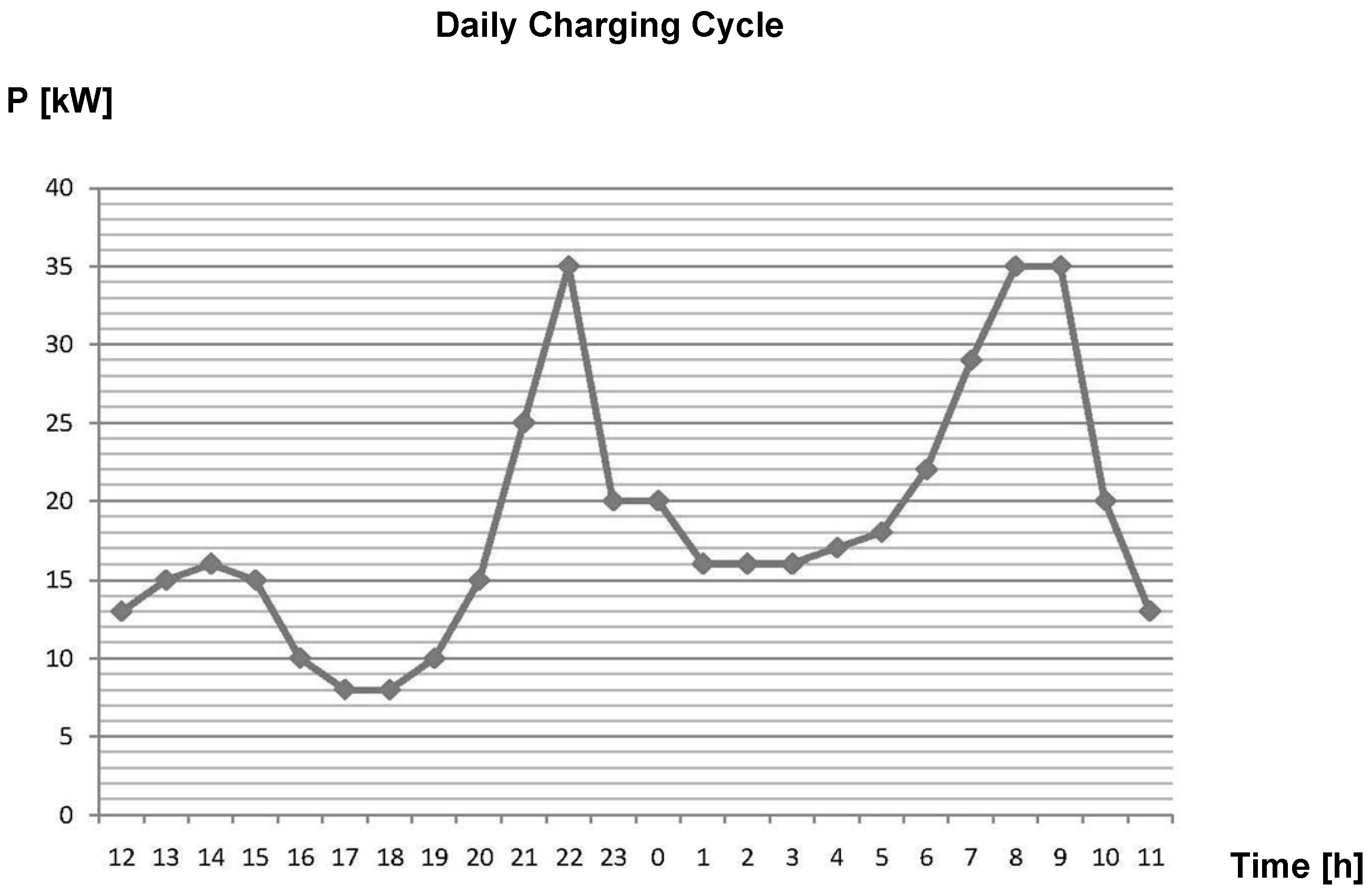
Depending on the installation’s requirements, the GS architectures can vary. In general, it is beneficial to use machines of different capacities and adjust their use according to the load condition at any given time. A typical example is the electric power generation plant on large ships. However, this is not the most common situation in most cases. In other words, a single GS is used to supply power to all loads available under all conditions, leading to inefficient usage, because the angular speed of the motor is always the same in order to maintain constant frequency in the output voltage. In those conditions, the output power of the engine will be at its optimum, yet it hardly ever reaches that state mainly due to the charge cycles which are characterized by a variable profile (see
Figure 2) unless the machine is working at a constant load, in parallel with the network or in cogeneration mode.
2.4. Variable-Speed Generation
The fact that diesel generators (GSs) operate well below their nominal power (NP) level results in their improper functioning. The engines have been designed and optimized for operation at around 70–80% of their NP, where the temperature, pressure and turbulence of the gas inside the engine combustion chamber facilitate proper fuel combustion and ensure correct adjustments between moving parts. Operating outside this design range leads to incorrect adjustments, causing oil leakage from the exhaust components and injector nozzles, leading to premature engine degradation over time. Additionally, since the engine operates below its optimal point, fuel consumption is higher than it should be if the engine were operating at its optimum. As evidence shows, inappropriate use of the GS results in a shortened engine lifespan.
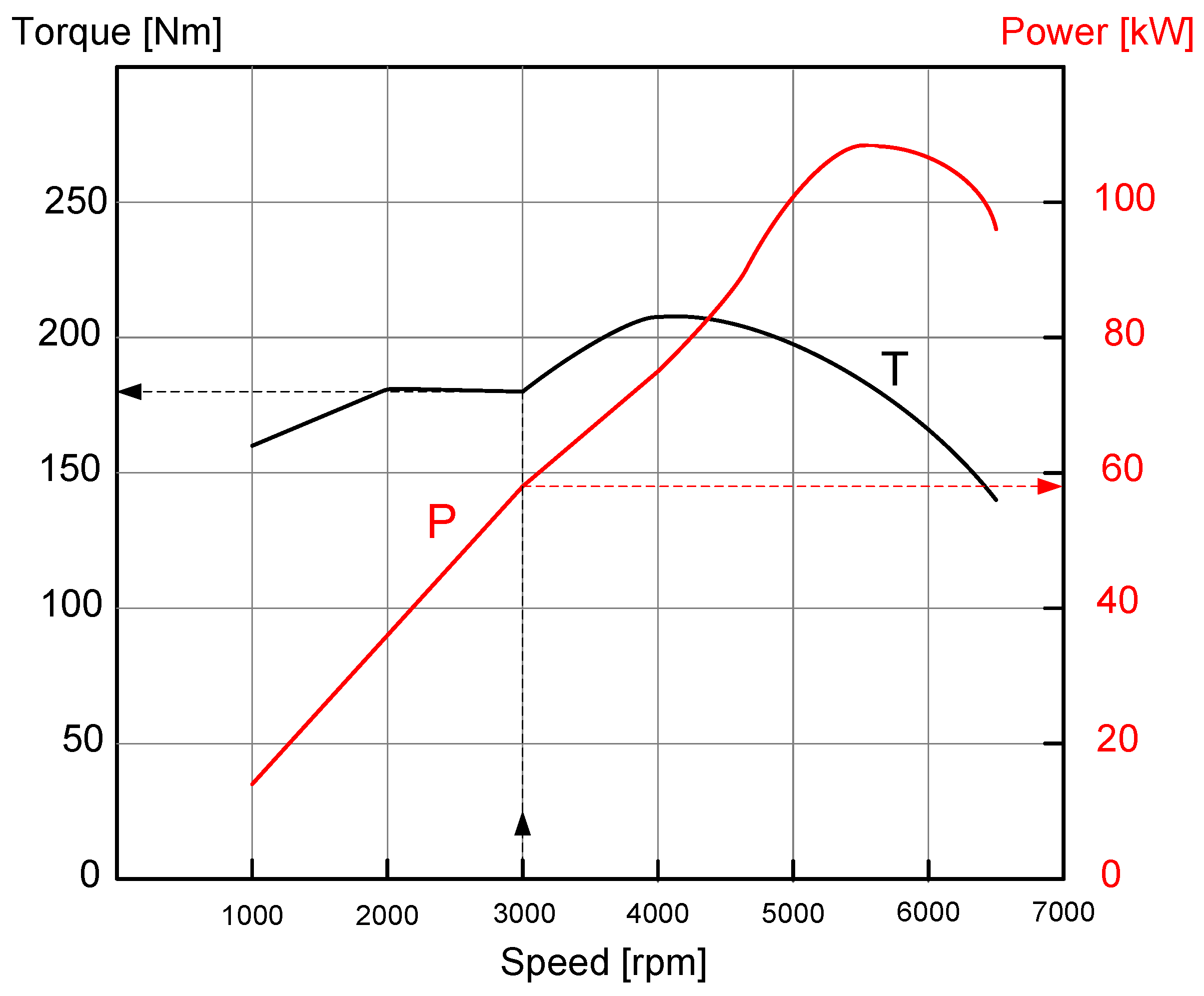
Given that the motor’s rotational speed in a GS remains constant, the NP of the GS represents the power that the engine can develop at its nominal speed, excluding losses. However, it is known that the power curve of the thermal engine shows linear behavior in that range. There, the power supplied by the engine is proportional to its rotational speed; although the engine can deliver more power than the value reflected in the nominal power of the GS, it cannot be effectively used due to the requirement to maintain constant speed. This can be observed in
Figure 3, where, for a rotational speed of 3000 r.p.m. (revolutions per minute, corresponding to a two-pole synchronous alternator), the maximum power supplied by the engine is around 58 kW. However, within the linear section of the curve, it can reach up to approximately 97 kW. Consequently, if there is a need for 75 kW at 3000 r.p.m., a larger and heavier engine than theoretically appropriate must be selected for the GS, increasing the machine’s weight, cost, maintenance expenses and fuel consumption [
13,
15].
On the order hand, when power requirements are much lower than the nominal power (NP), the engine’s speed could be lower than the nominal speed, thus operating at this optimal point.
These issues become particularly significant in hard-to-reach areas or environmentally protected zones. In such cases, where fuel transportation is challenging due to the machine’s location, as well as the weight of the machine for transportation and installation, and the maintenance periods, there is a need to design more efficient machines in terms of fuel consumption, weight and maintenance.
All these problems mean that in many applications it is essential to resort to variable-speed techniques in which the combustion engine will always be rotating at the optimal speed to the load applied to the machine, which makes the operation of the machine itself more efficient and therefore reduces the periods of maintenance required.
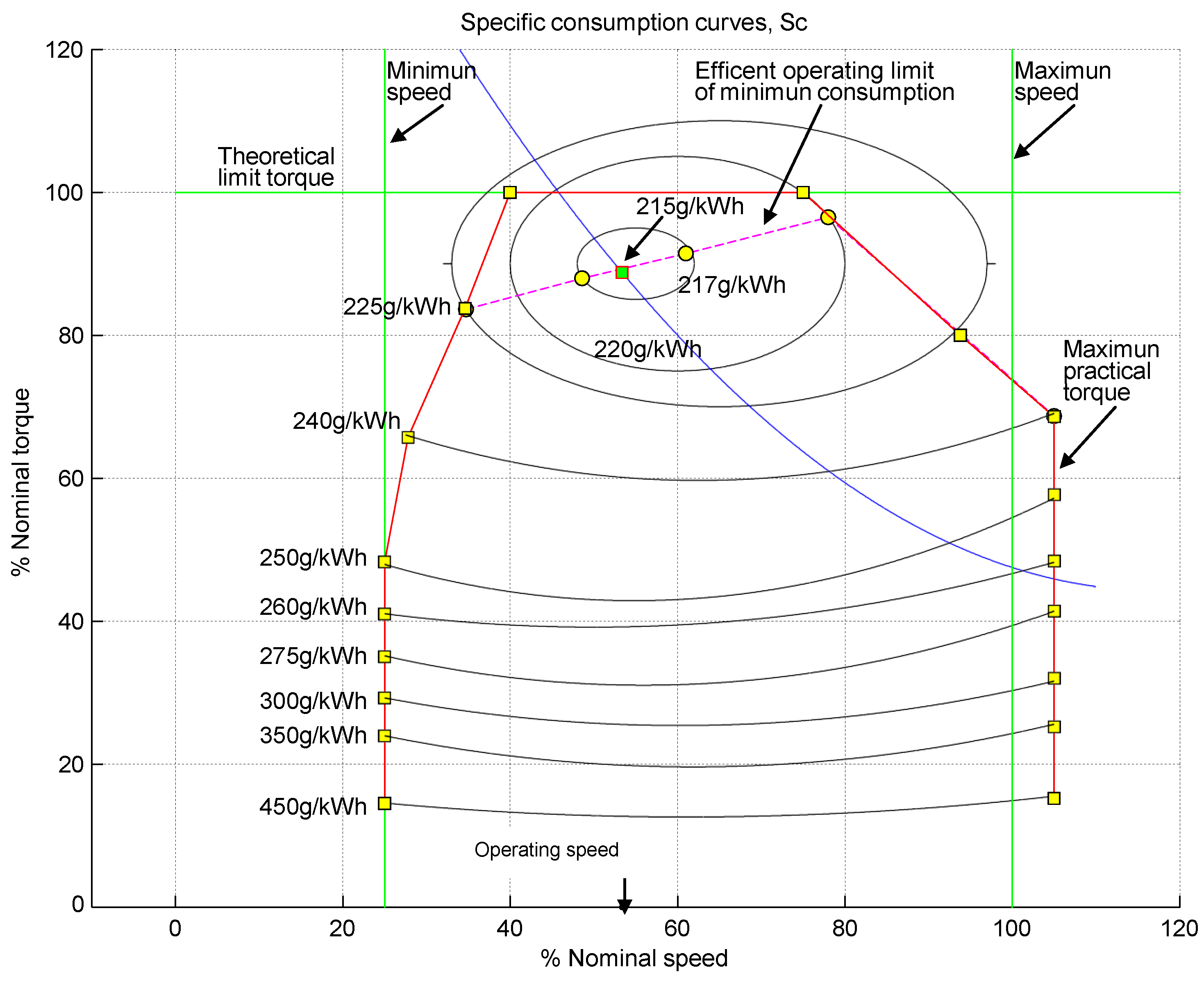
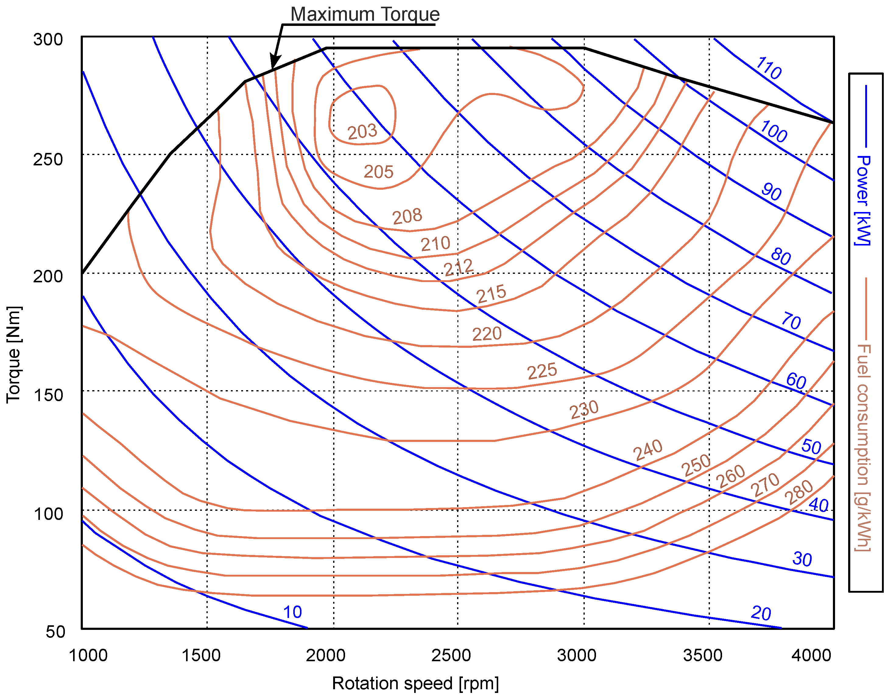
In order to obtain the optimal operating point of the engine, which is defined as one whose fuel consumption is minimal for a given power, we start from specific curves of a diesel engine (similar to that in
Figure 4), which represent the specific consumption in g/kWh for each speed and engine load. These curves are digitalized, establishing the operating point of the engine, which can be seen in
Figure 5. In this figure, the green lines represent the theoretical operating limits of the engine (an ideal one with a constant maximum torque) and the red line represents the actual torque limits of our engine. A single isopower curve (blue parabola) is shown to avoid complicating the view of the figure. The intersection point of this curve with the curve that defines the working area of the engine (dashed line in magenta) will provide the optimal working point of the engine (speed- and consumption-specific) for those given conditions.
As can be seen in
Figure 5 for 45% of the nominal power input, which is represented by the parabola whose branches protrude from the figure as a whole, this intersects with the work curve of the engine at a point marked with a square green background, and this point provides the specific consumption data for that input value (215 g/kWh). At about this point, a straight line is drawn parallel to the vertical axis (represented by an arrow on the x-axis), with its intersection with the horizontal axis providing the required speed data (53.38% of the nominal speed). Also,
Figure 5 shows the specific consumption for the given power input at a nominal speed (260 g/kWh approx.), which represents a fuel saving of around 20%.
In this way, the optimal point (engine speed) and specific consumption Sc (gr/kWh) are obtained for a given power from the curves of isoconsumption. That speed is then compared with that corresponding to a constant speed generator, showing a notable fuel saving.
Finally, we shall highlight the weight of the machine, because a larger engine will be necessarily small and therefore less heavy for the same nominal power of the machine, as it leverages the entire power curve of the thermal engine.
From the electrical standpoint, one advantage of having a variable-speed generator is that the output frequency of the machine does not depend on its angular speed, thus remaining very constant with load variations. This is beneficial for loads sensitive to frequency variations. In addition, the harmonic content of the output will be lower compared to a conventional machine as the power electronics required in the variable-speed machine can adequately control this aspect.
3. Application Example
This section describes the designed equipment, which has been tested during two Spanish Antarctic Campaigns in the SAB “Gabriel de Castilla” (corresponding to the XXX and XXXI Antarctic Campaigns of the Spanish Army) [
16], on the island, which will run for approximately four months, the duration of the austral summer.
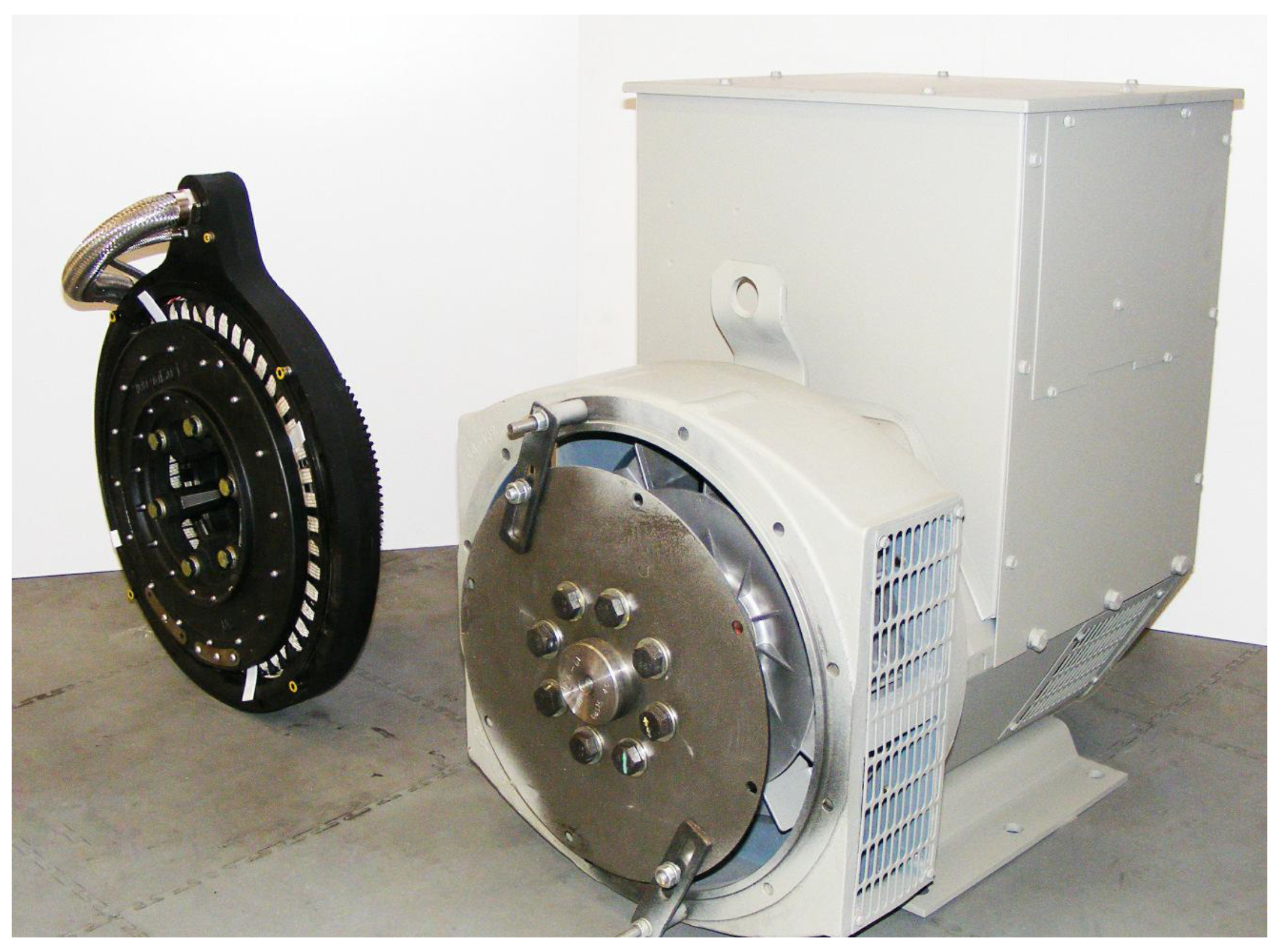
This equipment is a 50 kVA machine, which operates with a variable speed of 1200–2400 “r.p.m”, with a PMG (permanent magnets generator) featuring 16 poles and axial flux that operates at a frequency of 50 or 60 Hz. It features a three-phase output with neutral and two selectable voltages: 120/208 V and 230/400 V. Unlike standard alternators, the machine’s alternator is not connected through mounting plates. Instead, the polar wheel functions as the engine’s flywheel, replacing it. The stator is directly attached to the engine block using screws, making the alternator connection much more rigid and vibration-free. As depicted in
Figure 6, the difference in size and weight between the two machines is noteworthy, considering they both have the same power output.
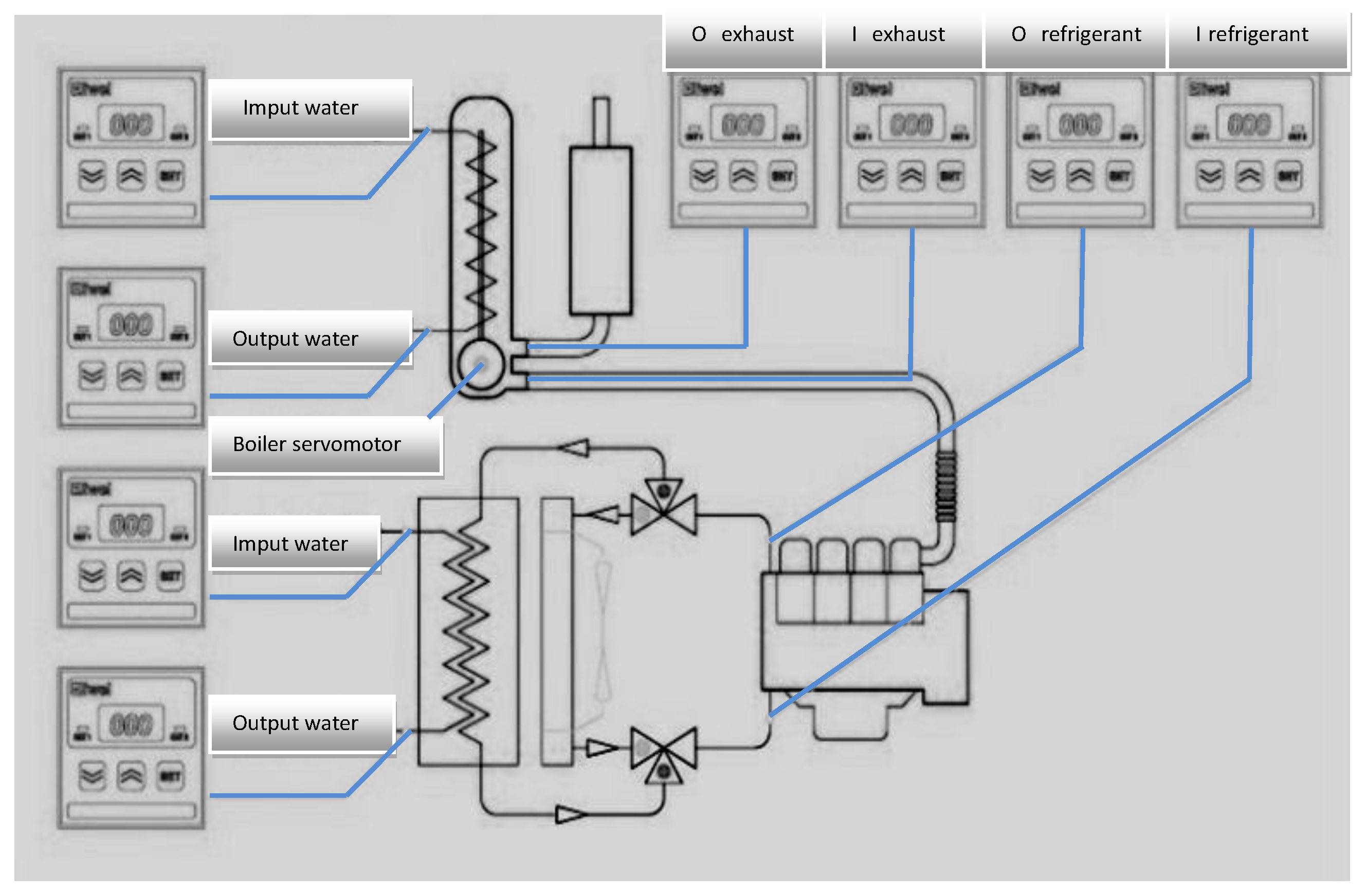
Furthermore, the designed equipment includes a heat recovery system for the engine, comprising a 500 L water tank with an air-to-air heat exchanger and liquid-to-liquid heat exchanger to recover the heat from the exhaust gases and the engine’s cooling fluid. All these components are integrated into the same frame (see
Figure 7).
Between the alternator and the output, there is a power conditioning unit based on an uncontrolled rectifier at the alternator’s output, providing a direct current (DC) bus to supply a DC/DC converter that maintains a constant 800 VDC output. Subsequently, an IGBT-based inverter forms the three-phase output. The neutral is supplied by an intermediate connection in the DC capacitors.
With this described architecture, the machine can operate as a standalone generator (GS) in island mode (as the sole supplier of power to the load), as a grid watchdog (in the case of main voltage failure supply, all the power in emergency mode), in parallel with other generators, at a fixed load, or in load sharing by drop.
We use the variable-speed thermal engine Deutz TD 2011 LO4W, (Deutz Spain. Madrid, Spain) which can be classified as a standard engine given its structural and operational characteristics.
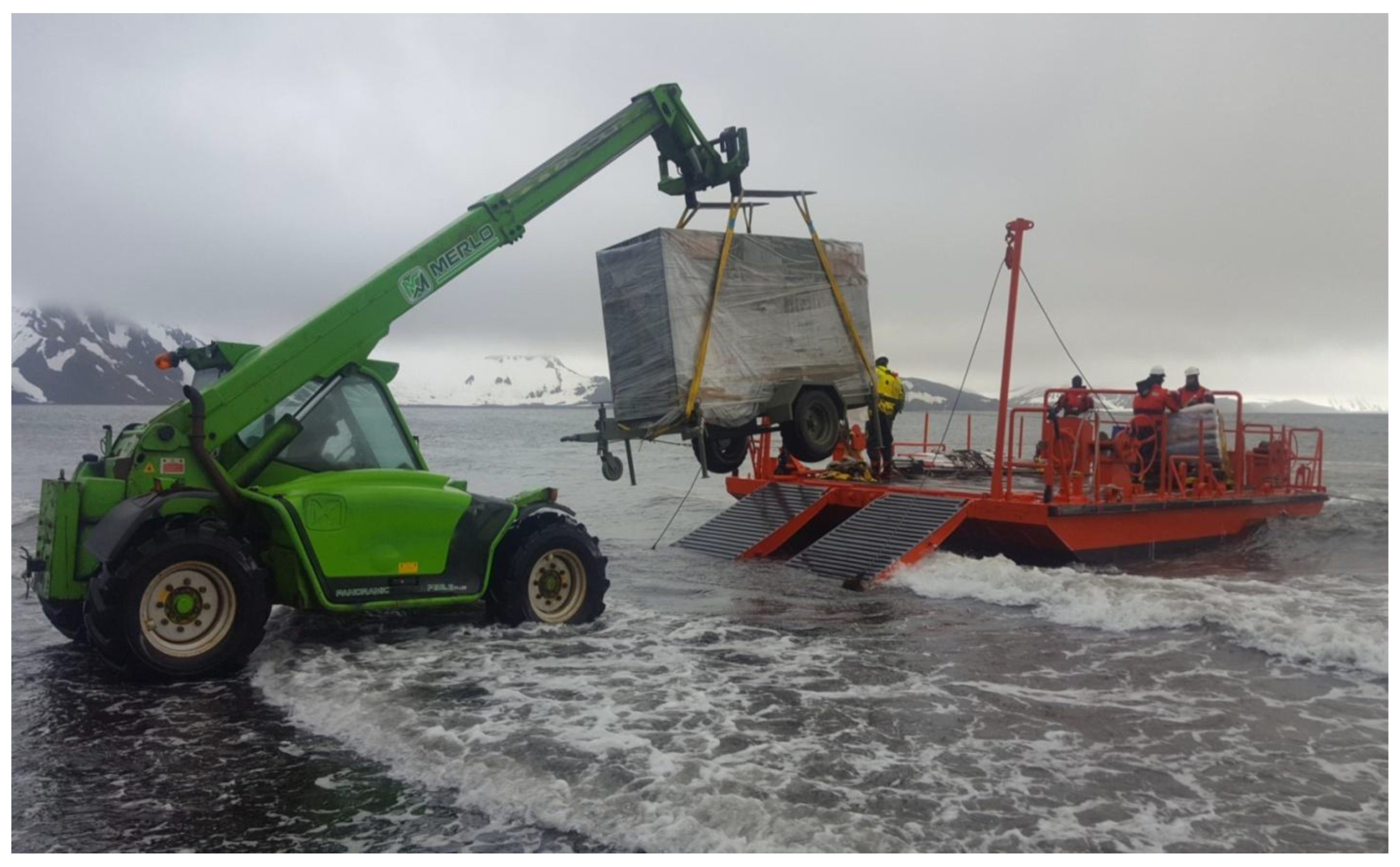
The engine-alternator assembly, along with the heat recovery system, is adapted in a trailer frame, around a soundproof cover as shown in
Figure 8. This picture portrays the unloading phase of the designed equipment on Decepcion Island for its test and the SAB “Gabriel de Castilla”.
For the specific case of the SAB “Gabriel de Castilla”, the fuel for the generators must be supplied by boat, from Punta Arenas (Chile) or Ushuaia (Argentina), with a 4-to-5-day delivery time from the SAB. This figure shows how crucial fuel savings are. Not only are the apparent economics important in this case, but, since the SAB is in a Specially Protected Area [
17], it is also important that the carbon footprint is as minimal as possible, so fuel consumption should be reduced.
4. Results
The machine was connected to the electrical power generator system of the SAB, with a constant demand of 10–13 kW during certain hours; during base activity and during nighttime rest periods, it was disconnected. The addition of a heat recovery system increased its performance up to 40%. Furthermore, the recovery heat was integrated into the base’s domestic hot water (DHW) circuit, thus taking advantage of all the features of the machine and achieving under these conditions fuel savings of approximately 20% per research campaign.
The data provided by the ECU (Electronic Control Unit) was used to calculate the fuel savings achieved with the use of the equipment installed with respect to the main generators of the base. Sets of measurements were taken at different times: the generated power (10 and 13 kW), total fuel consumption on the base (5.19 and 6.80 l/h), and designed equipment fuel consumption (3 and 4.2 l/h). Assuming linear fuel consumption, the total fuel of both the base generators and the equipment installed could be calculated (for the intermediate values).
The fuel saving of the equipment with the head recovery system is calculated similarly to that of the previously mentioned equipment. An average time is estimated for operation of the electric water heater of the base of which the technical data are known. With both values (electrical and thermal) of the approximate total fuel savings, thanks to technical data, an average of the running time of the electric water heater is estimated at about 30 liters of fuel per day, for a total of about 156 liters per day, which means an approximate saving of 20% of the total fuel consumed at the base by the main generators.
Likewise, to estimate the performance of the installed equipment, we start with the calorific capacity of the fuel used (diesel), which is related to the obtained power (heat and electrical) of the machine.
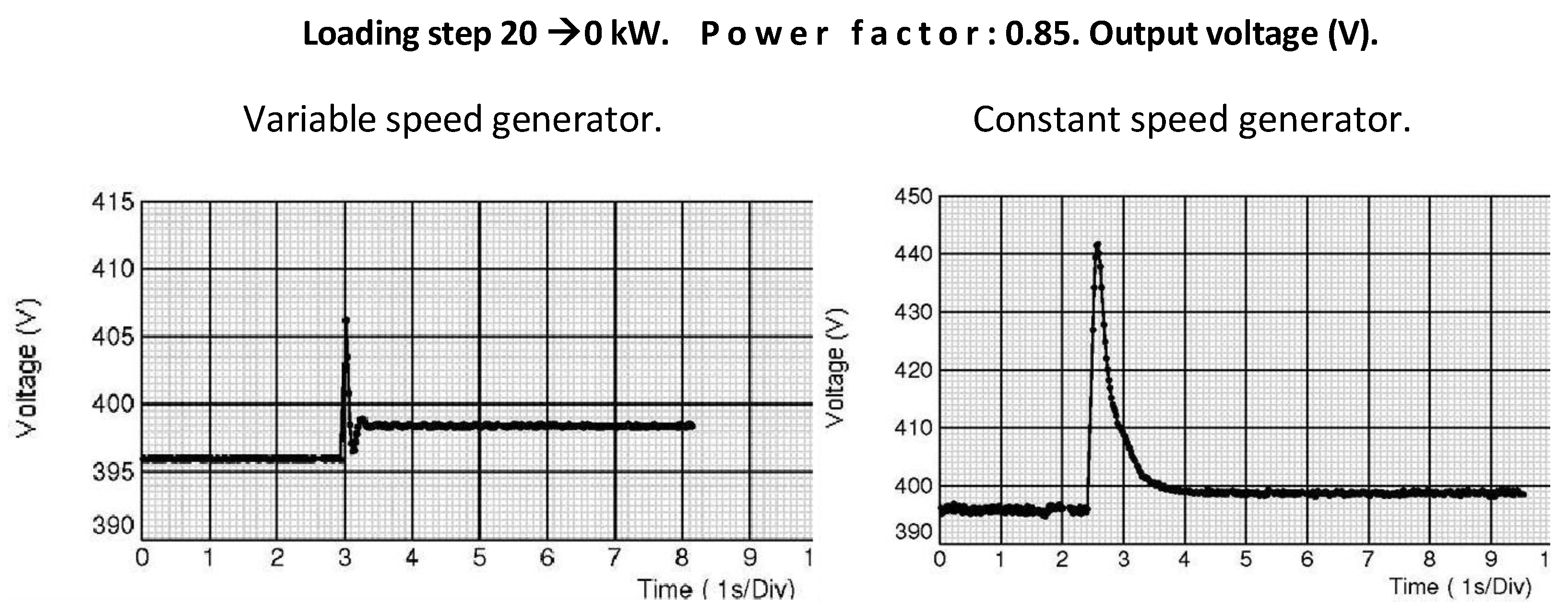
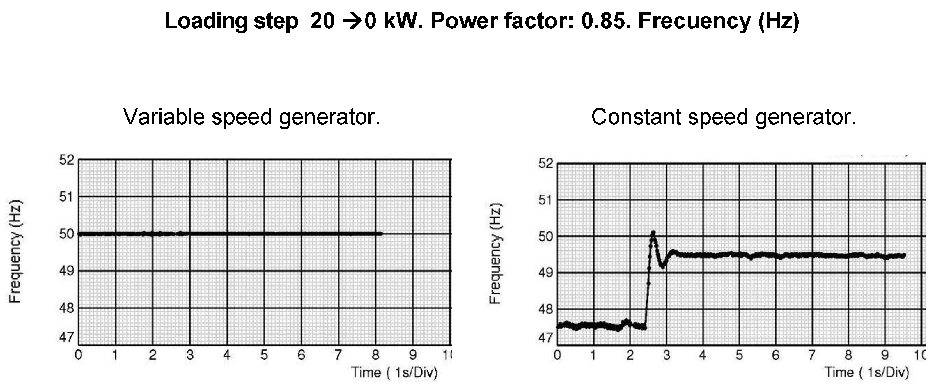
Regarding the electrical behavior of the installed equipment, the machine’s response to a negative load step of 20 kW and power factor of 0.85 can be seen, both for a standard machine of 50 kVA, and in the designed equipment (
Figure 9 and
Figure 10). The peak voltage value is approximately 42 V (10% of the value), which lasts about 1s, which can seriously damage electronic equipment, with an additional rise in frequency of around 2 Hz (a little less than 10%).
If the results are compared with those under the same load in the same conditions of the designed equipment, it can be seen that the variation in the voltage is around 10 V (2.5%), but only for 0.2 s, practically imperceptible. As for the frequency, it does not suffer any variation, since in this prototype, the frequency is independent of the engine speed. The graphs shown in
Figure 9 and
Figure 10 were obtained during the machine evaluation period, comparing the equipment present with a constant speed generator, with the same characteristics as the variable-speed machine presented, prior to its transfer to the Antarctic base.
Currently, work is being done to improve our equipment in several aspects: One of them and perhaps most important is to replace all the power electronics with a back-to-back architecture, which consists of a PWM rectifier connected though a DC bus to an inverter. The advantage of this configuration on the rectification stage is the possibility of controlling the power factor for the PMG alternator, thereby increasing performance and reducing the harmonics in the machine, although the control is somewhat more complex, requiring greater computing capacity, significantly increasing the price of this equipment.
Another aspect that is being worked on can be deduced from
Figure 9. In the graph corresponding to the RMS voltage, we can see a step response of approximately 10 V. Since in this case the step of the load is negative (ballast shedding), this 10 V implies a voltage peak in the machine’s terminals of that value. Although it is not significant for our purposes, this aspect can be improved. But in the case of a significant positive load step, the voltage drop produced may have a rise time that is not advisable, due to the time constant of the combustion engine. The response of the machine might be improved by placing energy storage equipment (batteries, supercapacitors, etc.) on the DC bus, which absorbs the drop, so it will not be appreciated in the value of the voltage of the connection or disconnection of important loads on the machine.
It is worth remembering that the machine has been working in a difficult environment due to the temperature and very saline environment, since the SAB it is located very close to the beach. It must also be taken into account that the type of loads used was not sensitive; that is, it was not necessary to have especially extreme quality in the electrical supply. Owing to that reason we choose simplicity and robustness as our design guidelines, increasing operation reliability, a crucial aspect in these circumstances. But in the case of using the machine for more demanding loads from the power quality point of view, this second version will undoubtedly be more appropriate.
5. Conclusions
The proper evaluation of this technique requires considering different power ranges for the machines. Thus, for a small machine (up to 50 kVA) and for certain load conditions, the associated extra cost and the difficulty of implementation are acceptable and the investment return is guaranteed, as explained in this article. On the contrary, a large machine is not a feasible solution for mobile equipment that must be installed in locations with strong environmental restrictions or in remote locations, due to the difficulties of transportation and use, despite the fact that the advantages of these machines are demonstrated.
One conclusion of this paper is that the size of the generator can be reduced, thereby optimizing fuel consumption and decreasing the carbon footprint. This is achieved with the described procedure, and the use of a variable-speed generator has been fundamental, allowing the selection of the optimal operating point for efficient fuel consumption.
The implementation and operation of the first prototype installed (at the SAB) has reduced fuel consumption by 20% compared to previous Antarctic campaigns, thus validating the procedure developed in this paper. This procedure will allow, in the future, the selection of other generators with an optimal size for similar installations with different output power levels.
We are currently undergoing a rapid energy transition to a decarbonized future. Variable-speed technology is an important option to consider as a necessary stepstone to that goal.
Author Contributions
Conceptualization, JJ.C. and JV.M.; Methodology, JJ.C. and JV.M.; Validation, JJ.C. and JV.M.; Investigation, JJ.C. and JV.M.; Resources, JJ.C., JV.M. and J.C.; Data curation, JJ.C., JV.M. and J.C.; Writing—original draft preparation, JJ.C., JV.M. and J.C.; Writing—review and editing, JJ.C., JV.M. and J.C.; Supervision, JJ.C., JV.M. and J.C. All authors have read and agreed to the published version of the manuscript.
Funding
The publication of this article has been funded by School of Industrial Engineering of UNED and by the Vice-Rectorate for Research of UNED.
Data Availability Statement
For any further information or access to data, figures or software, please contact the authors by email.
Acknowledgments
We express our gratitude to the Spanish Ministry of Defense, ET, for facilitating and supporting the construction of the generator equipment presented here, as well as its transportation to the “Gabriel de Castilla” SAB for testing and evaluation during the XXX and XXXI Spanish Antarctic Campaigns. The first author, J.J. Calero, was a member of the technical team in both campaigns. This research work is also part of the first author’s PhD thesis, carried out in the “Doctoral Program in Industrial Technologies” of the UNED.
Conflicts of Interest
The authors declare that they have no conflict of interest.
References
- Prakash, M.; Preetha, R. Supervisdory control of Standalone Wind—Solar Energy Generation Systems. In 2014 IEEE 8th International Conference on Intelligent Systems and Control (ISCO); Conference Paper; IEEE: New York, NY, USA, 2014. [Google Scholar]
- García Vera, Y.E.; Dufo-López, R.; Bernal-Agustín, J.L. Energy Management in Microgrids with Renewable Energy Sources: A Literature Review. Appl. Sci. 2019, 9, 3854. [Google Scholar] [CrossRef]
- Al-Quraan, A.; Al-Qaisi, M. Modelling, Design and Control of a Standalone Hybrid PV-Wind Micro-Grid System. Energies 2021, 14, 4849. [Google Scholar] [CrossRef]
- Kong, X.; Liu, X.; Ma, L.; Lee, K.Y. Hierarchical Distributed Model Predictive Control of Standalone Wind-Solar-Battery power System. J. Artic. IEEE Trans. Syst. 2019, 49, 1570–1581. [Google Scholar] [CrossRef]
- Shayani Amaral, S.; Gonçalves de Oliveira, M.A. A New Index for Absolute Comparison of Standalone Photovoltaic Systems Installed at Differen Locations. IEEE Trans. Sustain. Energy 2011, 2, 495–500. [Google Scholar] [CrossRef]
- Barbosa, E.J.; Acevedo, G.; Cavalcanti, C.M.; Cavalcante, V., Jr.; Bradaschia, F.; Limongi, L. Junction box integrade irradiance estimator for photovoltaic modules basade on IoT technology. IEEE Trans. Ind. Electron. 2024, 71, 14135–14145. [Google Scholar] [CrossRef]
- Mignoni, N.; Carly, R.; Dotoli, M. Layout optimization for photovoltaic panels in solar power plant via a MINLP approach. IEEE Trans. Autom. Sci. Eng. 2023, 22, 18148–18161. [Google Scholar] [CrossRef]
- Ghassami Akbar, A.; Sadeghzadeh Mohammad, S. A communicaction based method for PSC. Detection and GMP tracking under PSC. IEEE Trans. Ind. Inform. 2019. [Google Scholar] [CrossRef]
- Debacche, M.; Meziane, F.; Bekhti, A.; Tata, M. Desing and sizing of wind blades based on generator parameters for samll wind turbines for low wind regions. In 2023 2nd International Conference on Electronics, Energy and Measurement (IC2EM); IEEE: New York, NY, USA, 2023. [Google Scholar]
- Grama, A.; Petreus, D.; Etz, R.; Patarau, T. Fuel Consumption Reduction of a Diesel-Electric Power Generator. In 2015 38th International Spring Seminar on Electronics Technology (ISSE); Conference Paper; IEEE: New York, NY, USA, 2015. [Google Scholar]
- Agajie, T.F.; Fopah-Lele, A.; Amoussou, I.; Ali, A.; Khan, B.; Mahela, O.P.; Nuvvula, R.S.S.; Ngwashi, D.K.; Soriano Flores, E.; Tanyi, E. Techno-Economic Analysis and Optimization of Hybrid Renewable Energy System with Energy Storage under Two Operational Modes. Sustainability 2023, 15, 11735. [Google Scholar] [CrossRef]
- Guiles, P.; Ross, M.; Sumanik, S. Modelling Prime Diesel Electric Generator Fuel Consumption across Genset Sizing. In 2020 IEEE Electric Power and Energy Conference (EPEC); Conference Paper; IEEE: New York, NY, USA, 2020. [Google Scholar]
- Gallardo-López, F.; Hernández-Chontal, M.A.; Cisneros-Saguilán, P.; Linares-Gabriel, A. A Development of the Concept of Agroecology in Europe: A Review. Sustainability 2018, 10, 1210. [Google Scholar] [CrossRef]
- Casado, J.A.; Nieto, J.F.; Blázquez, F.; Platero, A.C. A monitoring system for diesel engine driven generators based on electric power out oscillation assessment. IEEE Trans. Ind. Appl. 2016, 53, 3182–3188. [Google Scholar] [CrossRef]
- Suryoatmojo, H.; Aulia, A.R.; Riawan, D.C.; Dzulfikar, R.D.; Prabowo; Suwito. Optimal control of diesel engine generator using variable speed permanent magnet synchronous generator based on fuzzy controler. In 2022 10th International Conference on Smart Grid and Clean Energy Technologies (ICSGCE); Conference Paper; IEEE: New York, NY, USA, 2022. [Google Scholar]
- BAE (Base Antártica Española del ET). XXX y XXXI Campaña. Available online: https://ejercito.defensa.gob.es/unidades/Antartica/antartica/index.html (accessed on 22 January 2018).
- MICIIN. Spanish Polar Committee and Sapnish Antarctic Bases, Tratado Antártico. Available online: https://www.ciencia.gob.es/en/Organismos-y-Centros/Comite-Polar-Espanol.html (accessed on 18 February 2022).
| Disclaimer/Publisher’s Note: The statements, opinions and data contained in all publications are solely those of the individual author(s) and contributor(s) and not of MDPI and/or the editor(s). MDPI and/or the editor(s) disclaim responsibility for any injury to people or property resulting from any ideas, methods, instructions or products referred to in the content. |