Article

Three-Switching-Surface Nonsingular Fast Terminal Sliding Mode Control for Two-Phase Buck Converters Powering DC Bus of Permanent Magnet Synchronous Motor Drives


School of Electrical Engineering, Southeast University, Nanjing 210096, China
*
Author to whom correspondence should be addressed.
Electronics 2026, 15(10), 2024; https://doi.org/10.3390/electronics15102024
Submission received: 7 April 2026 / Revised: 29 April 2026 / Accepted: 30 April 2026 / Published: 9 May 2026
(This article belongs to the Section Power Electronics)

Abstract

Aiming to improve the robustness of two-phase buck converters powering DC bus of permanent magnet synchronous motor drives, this article presents a novel voltage regulation scheme. The proposed scheme comprises a three-switching-surface nonsingular fast terminal sliding mode controller (TSS-NFTSMC) for output voltage regulation and a current balancing controller to equalize the inductor currents. Due to the fast terminal sliding mode surface, the output voltage error converges more rapidly both when far from zero and when approaching zero. The phase plane is split into four regions by three independent switching surfaces. Based on the region where the sliding variable resides, the TSS-NFTSMC can directly decide the number of enabled high-side switches, which helps suppress internal disturbances effectively. The stability and convergence of the presented control system are verified via Lyapunov stability analysis. The convergence property of TSS-NFTSMC is independent of the current controller. Both simulation and experimental results demonstrate that the proposed control strategy achieves satisfactory dynamic response and strong disturbance rejection capability.

1. Introduction

The pursuit of high-efficiency, reliable, and compact power conversion has solidified the status of DC-DC buck converters as essential components in critical sectors such as photovoltaic generation, energy storage, and aviation [1,2]. Permanent magnet synchronous motors (PMSMs) have been widely applied in numerous fields [3,4,5,6], such as electric vehicles, aerospace, and medical equipment. Voltage fluctuations of the power supply and sudden changes in the bus current of motor drivers will cause bus voltage fluctuation in PMSM drives. Such bus voltage fluctuations introduce disturbances and even limit the output capability of motor drivers. Integrating a buck converter at the front stage of the motor driver is a common solution to this problem.
While single-phase designs are common, the transition to a two-phase interleaved architecture offers substantial improvements: it enables power sharing that drastically shrinks the required size of inductors and switches, while simultaneously smoothing out current ripples [7]. Addressing the control challenges inherent in this sophisticated topology, the present study investigates novel approaches for precise voltage regulation in two-phase buck converters.
In practical implementations, the dynamic behavior of buck converters is frequently compromised by a confluence of parametric ambiguities and stochastic external perturbations. A primary source of intrinsic nonlinearity stems from the filter inductors, whose magnetic permeability fluctuates significantly under high flux density conditions, leading to saturation effects that deviate from ideal linear models. Compounding this issue are exogenous disturbances arising from volatile input supply rails, abrupt load transients, unmodeled high-frequency dynamics, and inevitable sensor measurement noise. Many advanced control schemes have been proposed for disturbance rejection [8,9,10]. To address the challenges of disturbances in buck converters and ensure the robustness of system performance, numerous targeted control strategies have been developed. These range from classical strategies like sliding mode control (SMC) [11] and proportional-integral-derivative (PID) [12,13], to more advanced frameworks including adaptive control [14,15], backstepping techniques [16,17], model predictive control (MPC) [18], and active disturbance rejection control (ADRC) [19]. Furthermore, intelligent control schemes have emerged as powerful alternatives for handling such complex, uncertain systems [20,21].
SMC has garnered significant acclaim within the control community, primarily attributed to its inherent resilience against system uncertainties. Early advancements focused on augmenting SMC with extended state observers (ESO) to counteract unmatched disturbances [22], while other studies introduced composite quasi-SMC frameworks to mitigate the destabilizing negative-resistance characteristics of constant power loads [23]. Furthermore, dead-beat terminal SMC strategies have been deployed to address simultaneous fluctuations in load, input, and reference voltages [24]. A critical limitation shared by these conventional approaches is their reliance on pulse width modulation (PWM)-based averaged models. While such models ensure that state variables track reference trajectories within a bounded error, they inherently fail to capture high-frequency switching ripple dynamics [25,26]. In contrast, leveraging the intrinsic switching nature of SMC—where the sliding variable oscillates around the manifold to directly actuate power switches—enables the deployment of controllers on precise switching models [27,28,29,30]. This paradigm shift has catalyzed the development of finite-time second-order [31] and terminal SMC algorithms [32], which drastically shorten convergence periods. Additionally, the exploitation of switching dynamics has facilitated sensor-less operations via finite-time observers that reconstruct voltage derivatives [33], and has enabled suboptimal control laws that maximize transient response by saturating current limits [34]. Despite these substantial achievements in single-phase topologies, a significant research gap persists. The direct translation of these switching-model-based SMC strategies to multiphase buck converters remains largely unexplored. This hesitation stems from the compounded complexities of inter-phase current balancing and the synchronized coordination of multiple switching devices, challenges that render single-phase solutions insufficient for multiphase applications.
The phase-shift PWM strategy stands as the predominant paradigm for orchestrating multiphase buck converters, serving as the foundation for various averaged modeling frameworks [35,36,37,38]. Within this domain, digital PID (D-PID) controllers have been engineered to ensure precise voltage regulation, often augmented by current-error feedback loops to enforce inductor current balancing [35]. Addressing the stringent robustness requirements of electric vehicle applications, researchers have introduced multiple-input multiple-output control architectures [36], which achieve phase current equalization through the symmetric dispatching of reference currents to individual phase controllers. Parallel advancements have been made in active disturbance rejection control (ADRC). Notably, linear ADRC schemes incorporating reference differential feedforward and cascaded linear ESO have been deployed [37], while improved linear ADRC (ILADRC) variants [38] further refine performance by rectifying disturbance estimation errors. Empirical evidence confirms that these approaches, typically structured around a dual-loop configuration, significantly enhance system resilience. In such architectures, the inner loop leverages identical current references across parallel buck stages to naturally facilitate current sharing, while the phase-shift PWM mechanism ensures effective interleaved operation. However, the validity of the averaged model approximation is contingent upon a sufficiently high switching frequency relative to the system dynamics. A critical bottleneck emerges when demanding ultra-fast transient responses: the requisite rapid variation in control signals can outpace the fixed carrier frequency. Under these conditions, the averaging assumption breaks down, giving rise to internal high-frequency disturbances that prove intractable for standard compensation techniques, thereby limiting the efficacy of averaged-model-based controllers in high-bandwidth scenarios.
While averaged models often obscure high-frequency dynamics, switching models provide a precise representation of these characteristics, enabling the direct application of SMC to multiphase buck converter topologies [39,40,41,42]. Early implementations, such as hysteresis-based SMC [39], utilize the aggregate inductor current as a reference, where the combined output of voltage and current loops dictates the switching state of individual phases. Although this approach successfully enforces current sharing, it inadvertently induces significant cross-coupling dynamics between the voltage and current regulation loops, potentially compromising system stability. Subsequent research has focused on ripple mitigation through dedicated multiphase SMC strategies [40], evolving into fixed-switching frequency interleaved SMC (FSFISMC) [41]. The latter achieves stable interleaved operation and precise current balancing by defining novel switching manifolds for slave phases. However, a critical limitation persists in both [40,41]: the interleaving mechanism relies heavily on integrators, which inherently introduces phase lag and degrades the transient response speed. Alternatively, zero average dynamics SMC (ZADSMC) [42] employs a master-slave topology where the first phase acts as the leader, compelling the slave phases to track the current trajectory of the leader. While this configuration guarantees effective current equalization, its practical deployment is hindered by excessive computational complexity. Specifically, ZADSMC necessitates multiple high-speed analog-to-digital conversions and intensive real-time calculations within a single PWM period, posing significant challenges for standard digital implementation. To address this issue, a three-switching-surface nonsingular terminal sliding mode control (TSS-NTSMC) was proposed [43]. By designing three distinct switching surfaces, direct and precise control of the power switches in a two-phase buck converter was successfully achieved while maintaining remarkably low computational complexity. However, it is important to note that the sliding surfaces employed in [43] are merely common nonsingular terminal sliding surfaces, which inherently limits their dynamic performance. Consequently, the overall convergence speed remains suboptimal and relatively sluggish when the output voltage error is significantly large.
To address the aforementioned issues, this article proposes a three-switching-surface nonsingular fast terminal sliding mode control (TSS-NFTSMC). This method achieves faster convergence when the output voltage error is large, while also exhibiting finite-time convergence characteristics on the terminal sliding surface when the output voltage error approaches zero. Furthermore, by utilizing the three-switching-surface design, the proposed TSS-NFTSMC, together with a current controller, enables direct control of the power switches in a two-phase buck converter. Finally, to further validate the effectiveness of the proposed control scheme, simulations and experiments are conducted. The simulation and experimental results demonstrate that the proposed control scheme exhibits fast response speed and provides excellent compensation for sudden changes in load current and input voltage.
The remainder of this article is structured to guide the reader from theoretical modeling to experimental validation. Section 2 establishes the mathematical foundation by deriving the dynamic model of the two-phase buck converter. Building on this framework, Section 3 details the formulation and implementation of the proposed control strategy. The efficacy of the design is then rigorously evaluated in Section 4, which presents comprehensive simulation data alongside experimental verification. Finally, Section 5 concludes the article by summarizing the key findings and implications.

2. Mathematical Model of Two-Phase Buck Converter

The circuit diagram of the two-phase buck converter is shown in Figure 1. The operating principle of the two-phase Buck converter was previously discussed in [39,40,41,42]. The switching model can be expressed as
L d i 1 d t = λ 1 ( t ) u i t u o t + d 1 ( t )
L d i 2 d t = λ 2 ( t ) u i t u o t + d 2 ( t )
C d u o d t = i 1 t + i 2 t i L ( t )
where L and C represent inductance and capacitance, respectively; u i t and u o t denote input voltage and output voltage, respectively; λ 1 ( t ) and λ 2 ( t ) indicate the states of the power switches in the first and second phases, respectively; i 1 t and i 2 t denote the inductor currents in the first and second phases, respectively; d 1 ( t ) and d 2 ( t ) denote the disturbances in the first and second phases, respectively; i L ( t ) represents the load current. If λ 1 t = 1 , the high-side power switch of the first phase is turned on and the low-side power switch is turned off. If λ 1 t = 0 , the high-side power switch of the first phase is turned off and the low-side power switch is turned on. The switching logic for the second phase is identical to that of the first phase.
Since the output voltage depends on both λ 1 t and λ 2 ( t ) , it is inconvenient to simultaneously output λ 1 t and λ 2 ( t ) through a single voltage controller. Therefore, models (1)–(3) are rewritten as
d 2 u o d t 2 = 1 L C u i t Γ v t 2 u o t + 1 L C d 1 t + d 2 t 1 C d i L d t
where Γ v t = λ 1 t + λ 2 ( t ) is the control input. A voltage controller is designed below, and its output is set as the control input Γ v t .
Assumption 1.
It is assumed that there exist positive constants  c 1 ,  c 2 , and  c 3  such that  d 1 t + d 2 t c 1 ,  d u o / d t c 2 , and  d i L / d t c 3 .
Differencing (1) and (2) gives the current model as
d i Δ d t = 1 L ( u i t Γ c t + d 1 t d 2 t )
where i Δ t = i 1 t i 2 t is the inductor current error, and Γ c t = λ 1 t λ 2 ( t ) is the control input of the current model.

3. Design of Voltage Controller and Current Controller

3.1. Control Structure

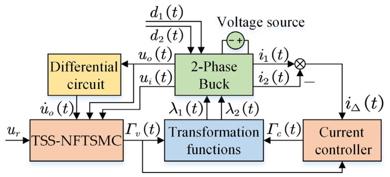
TSS-NFTSMC is designed for voltage model (4), while the current controller is designed for current model (5). The control block diagram is shown in Figure 2. TSS-NFTSMC determines the number of high-side power switches turned on in the two-phase buck converter based on the reference voltage, input voltage, output voltage, and the time derivative of the output voltage. This number can be 0, 1, or 2. When the number of high-side power switches turned on is 1, the current controller further determines whether the high-side power switch for the first or second phase is turned on based on the inductor current error. Therefore, the results from the TSS-NFTSMC and current controller can be converted into the power switch states of the two-phase buck converter via transformation functions.

3.2. Three-Switching Surface Nonsingular Fast Terminal Sliding Mode Control for Voltage

This part introduces the proposed TSS-NFTSMC. Compared to traditional linear sliding surfaces, terminal sliding surfaces exhibit finite-time convergence characteristics with faster convergence rates [24,44]. The attractors of terminal sliding surfaces demonstrate excellent convergence speeds near the reference value but exhibit reduced convergence speeds far from it. The fast terminal sliding surface achieves balanced convergence speeds both near and far from the reference value. The nonsingular fast terminal sliding mode surface further resolves the singularity issue in controllers [21]. The nonsingular fast terminal sliding surface is designed as follows:
s t = e t + 1 α e g h t + 1 β e ˙ p q t = 0
where e t = u r u o ( t ) ; α and β are the positive coefficients; g , h , p and q are the positive odd integers ( p > q and g / h > p / q ). The reference voltage u r is a positive constant.
To further analyze the advantages of the nonsingular fast terminal sliding surface, (6) is compared below with a nonsingular terminal sliding surface. The nonsingular terminal sliding surface can be expressed as
s t = e t + 1 β e ˙ p q t = 0
When s t reaches the sliding surface, e ˙ t in (6) can be written as
e ˙ t = β e t β α e g h ( t ) q p
By contrast, when s t reaches the sliding surface, e ˙ t in (7) can be written as
e ˙ t = β e t q p
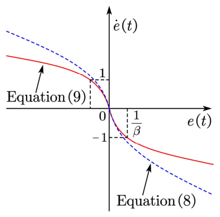
Figure 3 shows the curves for (8) and (9). It can be observed that (8) and (9) are similar when e t is near 0. This indicates that the convergence characteristics of the nonsingular fast terminal sliding surface (6) and the nonsingular terminal sliding surface (7) are similar when e t is near 0. Therefore, when e t is near 0, (6) exhibits finite-time convergence. When e t is far from 0, e ˙ t in (8) is relatively large. Therefore, when e t is far from 0, the nonsingular fast terminal sliding surface (6) converges more rapidly.
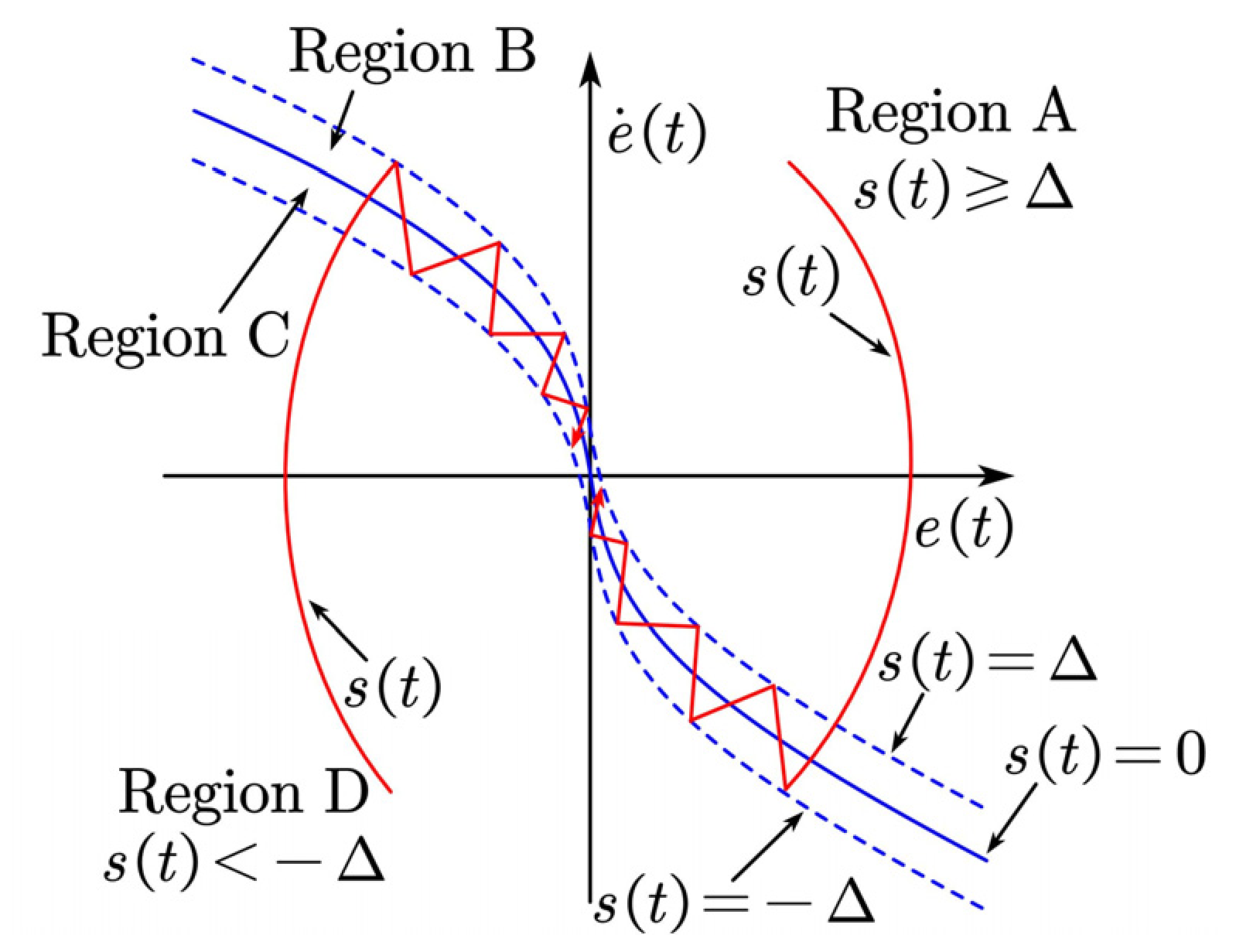
Figure 4 contains three switching surfaces: s t = Δ , s t = 0 , and s t = Δ . These three switching surfaces divide the phase plot into four regions: Region A ( s t Δ ), Region B ( s t < Δ and s t 0 ), Region C ( s t < 0 and s t Δ ), and Region D ( s t < Δ ). The TSS-NFTSMC is designed to determine which region the sliding variable s t resides in and to determine the number of high-side power switches to turn on based on the region where the sliding variable s t is located.
For the voltage model (4), the TSS-NFTSMC is designed as
Γ v t = Φ ( s i g n s t + s i g n s t + Δ + s i g n s t Δ + s i g n 2 u r u i t 2 + 1 )
where Δ > 0 is an adjustable coefficient, and the functions s i g n x and Φ x are
s i g n x = 1 ,   i f   x 0 ,   1 ,   i f   x < 0 ,      Φ x = 0 ,   i f   x 0 , x ,   i f   0 < x < 2 , 2 ,   i f   x 2 .

3.3. Convergence Analysis of TSS-NFTSMC

Theorem 1:
Considering the voltage model (4) with TSS-NFTSMC (10), the sliding variable  s t  and the voltage error  e t  will converge to near 0 within a finite time if the following conditions hold.
  • u i t > 0 ,  α > 0 ,  β > 0 , and  Δ > 0 ;
  • g ,  h ,  p  and  q  are the positive odd integers,  p > q , and  g / h > p / q ;
  • the input voltage  u i t  and the reference voltage  u r  are satisfied by  δ u i t / 2 + c 4 L C / 2 + c 2 / α + c 2 p / q / β + < u r < 1 δ / 2 u i t c 4 L C / 2 c 2 / α c 2 p / q / β  , where  δ ( 0 , 1 )  is a constant and  c 4 = c 1 / ( L C ) + 1 / ( 1 / ( α c 2 ) + p c 2 p / q 2 / ( β q ) ) + c 3 / C .
Proof. 
The Lyapunov function is designed as
V 1 t = 1 2 s 2 ( t )
Taking the time derivative of (11) yields
V ˙ 1 t = s ( t ) ( e ˙ t + g α h e g h 1 t e ˙ t + p β q e ˙ p q 1 t e ¨ t ) = s ( t ) ( u ˙ o t g α h e g h 1 t u ˙ o ( t ) p β q u ˙ o p q 1 t u ¨ o t )
Substituting (4) into (12) yields
V ˙ 1 t = s t u ˙ o t g α h e g h 1 t u ˙ o t    p β q u ˙ o p q 1 t 1 L C u i t Γ v t 2 u o t + 1 L C d 1 t + d 2 t 1 C d i L d t = p β q u ˙ o p q 1 t s t β q p u ˙ o 2 p q t β q g α h p e g h 1 t u ˙ o 2 p q t    1 L C u i t Γ v t 2 u o t 1 L C d 1 t + d 2 t + 1 C d i L d t
Case 1 ( s ( t ) > Δ ): In this case, the sliding variable s t is not near the sliding surface, and the controller operates in the reaching phase. According to the definition of TSS-NFTSMC (10), if s ( t ) > Δ , then TSS-NFTSMC (10) can be rewritten as
Γ v t = s i g n s t + 1
Substituting (14) into (13) yields
V ˙ 1 t = p β q u ˙ o p q 1 t s t β q p u ˙ o 2 p q t β q g α h p e g h 1 t u ˙ o 2 p q t      1 L C u i t s i g n s t + 1 2 u o t 1 L C d 1 t + d 2 t + 1 C d i L d t
Since p and q are positive odd integers, (15) can be written as
V ˙ 1 t = p β q u ˙ o t p q 1 s t β q p u ˙ o 2 p q t β q g α h p e g h 1 t u ˙ o 2 p q t 1 L C u i t s i g n s t + 1 2 u o t 1 L C d 1 t + d 2 t + 1 C d i L d t
Based on (16) and the definitions of c 1 , c 2 , c 3 , and c 4 , if u i t > 0 , then the following inequality can be obtained.
V ˙ 1 t p β q u ˙ o t p q 1 s t ( 1 δ ) u i t s i g n s t L C δ u i t s i g n s t L C u i t L C + 2 u o t L C + β q g α h p e g h 1 t c 2 2 p q t + c 4 s i g n s t
According to (17), if the following inequality is satisfied
δ 2 u i t + c 4 L C 2 u o t 1 δ 2 u i t c 4 L C 2
then one obtains:
s t 1 δ u i t s i g n s t L C u i t L C + 2 u o t L C + β q g α h p e g h 1 t c 2 2 p q t + c 4 s i g n s t 0
Substituting (19) into (17) yields
V ˙ 1 t δ 1 α + p β q u ˙ o t p q 1 u i t L C s t
According to (18), one obtains u i t c 4 L C / ( 1 δ ) . From (20), it follows that
V ˙ 1 t ρ s t
where ρ = c 4 δ L C / ( α L C ( 1 δ ) ) > 0 .
According to (11) and (21), if s ( t ) > Δ , then one obtains:
s ( t 0 ) s ( t 0 + t r ) d s t 0 t 0 + t r ρ d t
where t 0 is the initial time; t r is the moment at which the sliding variable s ( t ) reaches the interval [ Δ , Δ ] . Solving inequality (22) yields t r ( s t 0 ) / ρ . A similar method can be used to obtain t r ( s t 0 ) / ρ when s t < Δ . In summary, if s ( t ) > Δ , then t r ( s t 0 ) / ρ .
The above discussion addressed cases where inequality (18) is satisfied. Below, it will be introduced when inequality (18) does not hold. When inequality (18) is not satisfied, the reference voltage u r must meet certain conditions to enable the output voltage u o t to converge to the reference voltage u r . The condition that the reference voltage is required to satisfy is
δ u i t / 2 + c 4 L C / 2 + c 2 / α + c 2 p / q / β + < u r < 1 δ / 2 u i t c 4 L C / 2 c 2 / α c 2 p / q / β
There are two cases where inequality (18) is not satisfied: u o t < δ u i t / 2 + c 4 L C / 2 and u o t > 1 δ / 2 u i t c 4 L C / 2 . If u o t < δ u i t / 2 + c 4 L C / 2 and the reference voltage satisfies condition (23), then s ( t ) > Δ , i.e., Γ v t = 2 . At this point, the two-phase buck converter operates in its maximum output state, which drives the output voltage upward, causing it to approach the reference voltage. Similarly, if u o t > 1 δ / 2 u i t c 4 L C / 2 and the reference voltage satisfies condition (23), then s t < Δ , i.e., Γ v t = 0 . Under this condition, the two-phase buck converter operates in its minimum output state, causing the output voltage to decrease and thereby converge toward the reference voltage.
Case 2 ( s ( t ) Δ ): In this case, the sliding variable s t is near the sliding surface. At this point, the controller is in the sliding phase. When s t converges to near 0, the output voltage error e ( t ) will follow the convergence behavior of the nonsingular fast terminal sliding surface (6). The output voltage error e ( t ) will converge to near 0 within a finite time [21]. □

3.4. Current Controller Design

Two-phase buck converters contain two inductors. If the current in one inductor becomes excessively high while the current in the other inductor is too low, overcurrent conditions may occur in the inductors. Overcurrent in the inductors can lead to saturation or even damage. Therefore, designing a reliable current equalization algorithm is essential.
When the TSS-NFTSMC outputs 0, both high-side power switches are off. When the TSS-NFTSMC outputs 2, both high-side power switches are on. Therefore, when the TSS-NFTSMC outputs 0 or 2, it is impossible to adjust the difference between the two inductor currents by controlling the power switch states. When TSS-NFTSMC outputs 1, two scenarios exist: either the high-side power switch of the first phase is on ( λ 1 t = 1 and λ 2 t = 0 ) or the high-side power switch of the second phase is on ( λ 1 t = 0 and λ 2 t = 1 ). Therefore, in this case, the power switch states can be adjusted based on the difference between the two inductor currents to achieve inductor current equalization [43].
For the current model (5), the current controller is designed as
Γ c t = s i g n ( i Δ t ) ,   i f   Γ v t = 1 ,   0 , i f   Γ v t = 0   o r   Γ v t = 2 .
When Γ v t = 0 or Γ v t = 2 , Γ v t = 0 , which means the current controller (24) does not affect i Δ t at this moment. According to the current model (5), i Δ t is offset by the disturbances d 1 t and d 2 t at this time. When Γ v t = 1 , Γ c t = s i g n ( i Δ t ) , which means the current controller (24) will apply a counteracting force based on the difference between the two inductor currents, thereby driving i Δ t back to 0. According to TSS-NFTSMC (10), as the sliding variable s t traverses the sliding surface, there will inevitably be cases where Γ v t = 1 and cases where Γ v t = 0   o r   Γ v t = 2 . Therefore, i Δ t will alternatively be in phases where it is far from 0 and phases where it approaches 0. Substituting the current controller (24) into the current model (5) yields
d i Δ d t = 1 L ( u i t s i g n ( i Δ t ) + d 1 t d 2 t ) ,   i f   Γ v t = 1 ,   1 L ( d 1 t d 2 t ) , i f   Γ v t = 0   o r   Γ v t = 2 .
According to (25), by increasing the input voltage u i t , the rate at which i Δ t approaches 0 when Γ v t = 1 can be accelerated; in fact, the rate at which i Δ t approaches 0 when Γ v t = 1 can be significantly greater than the rate at which i Δ t moves away from 0 when Γ v t = 0   o r   Γ v t = 2 . Consequently, i Δ t can be maintained near 0.

3.5. Power Switch Coordination in Two-Phase Buck Converters

The number of high-side power switches turned on can be determined via the TSS-NFTSMC (10). When the number of high-side power switches turned on is 1, the current controller (24) can further determine whether the high-side power switch for the first phase or the second phase is turned on. Therefore, the state of all power switches can be determined based on the TSS-NFTSMC and the current controller. The outputs of the TSS-NFTSMC and the current controller can be converted into the state of the power switches through a transformation function. The transformation functions are designed as follows:
λ 1 t = 0 , i f   Γ v t = 0   o r Γ v t = 1 Γ c t = 1 1 , i f   Γ v t = 2   o r Γ v t = 1 Γ c t = 1
λ 2 t = 0 , i f   Γ v t = 0   o r Γ v t = 1 Γ c t = 1 1 , i f   Γ v t = 2   o r Γ v t = 1 Γ c t = 1
Based on Equations (26) and (27), the voltage controller Γ v t and the current controller Γ c t can be converted into the states of the switching transistors.

3.6. Hysteresis Comparator Design

The switch function s i g n · is used in both the TSS-NFTSMC (10) and current controller (24). High-frequency oscillations may occur when the sliding variable is at the switching surface. To avoid this phenomenon, s i g n · can be replaced with a hysteresis comparator [29]. The expression for the hysteresis comparator is
Ψ x , y = 1 ,   i f   x > y ; 1 ,   i f   x < y ; u n c h a n g e d ,   o t h e r w i s e .
Replacing the switching functions in the TSS-NFTSMC (10) and the current controller (24) with hysteresis comparators respectively yields
Γ v t = Φ ( Ψ s t , k 1 + Ψ s t + Δ , k 1 + Ψ s t Δ , k 1 + Ψ 2 u r u i t , k 1 2 + 1 )
Γ c t = Ψ ( i Δ t , k 2 ) ,   i f   Γ v t = 1 ,   0 , i f   Γ v t = 0   o r   Γ v t = 2 .
where k 1 < Δ and k 2 are positive constants.
The switching states of the two-phase buck converter can be directly controlled using the voltage controller (29) and current equalization controller (30). This design enables the proposed scheme to achieve a fast response. Additionally, the sliding surface in the voltage controller (29) is designed as a nonsingular fast terminal sliding surface. This design further improves the response speed of the controller. Therefore, the proposed control scheme is suitable for applications involving sudden heavy loads.

3.7. Controller Parameter Tuning

Larger values of k 1 and k 2 help reduce the switching frequency of the power switches, but they also cause an increase in voltage ripple and current ripple. Reducing the values of k 1 and k 2 will increase the switching frequency of the power switches, but voltage ripple and current ripple will decrease.
Δ is used to set the distance between the three switching surfaces. Increasing Δ reduces the switching frequency and meanwhile increases the voltage ripple.
After the sliding mode variable s ( t ) converges to the sliding surface, increasing β and decreasing α helps accelerate the convergence of the output voltage. However, excessively large β and excessively small α will cause system oscillations. The parameters g , h , p , and q shall be positive odd integers, satisfying p > q and g / h > p / q .

4. Simulation and Experimental Results

4.1. Simulation Results

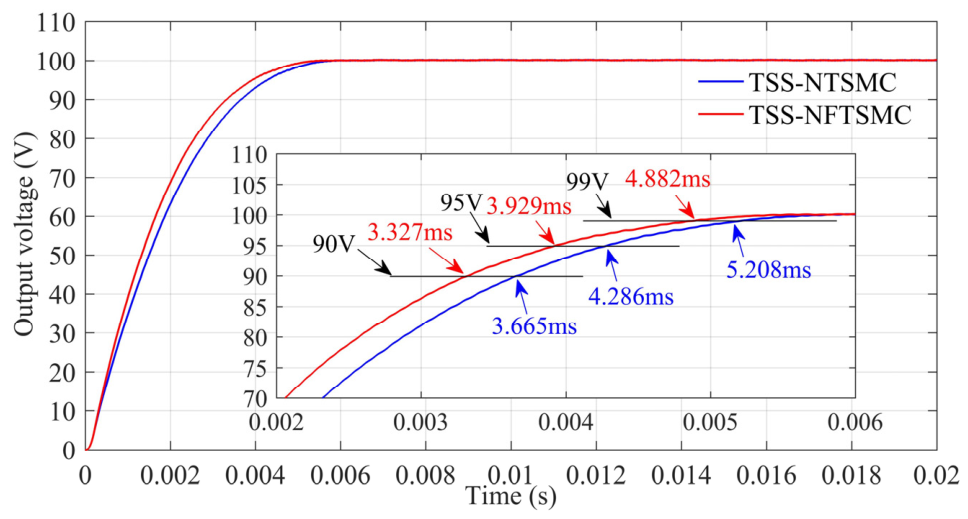
In this part, the efficacy of the proposed control strategy is validated through simulations implemented in MATLAB R2016a. The simulation environment utilizes a fixed-step Euler solver with a step size of 10 ns. Controllers are embedded within a triggered subsystem operating at a frequency of 50 kHz. The input and reference voltages are configured at 150 V and 100 V, respectively. The initial states for both the output voltage and inductor currents are set to zero. The circuit components include an inductance of 460 μH, a capacitance of 2160 μF, and a load resistance of 10 Ω. Furthermore, the controller gains and parameters are defined as follows: α = 5 , β = 3,500,000 , g = 9 , h = 5 , p = 5 , q = 3 , Δ = 1 , k 1 = 0.05 , and k 2 = 0.1 . To better validate the performance of the proposed scheme, TSS-NTSMC [43] is set as the comparison scheme. The parameter tuning principle for these control schemes is to accelerate the output voltage response as much as possible without oscillation. The simulation results are shown in Figure 5, Figure 6 and Figure 7.
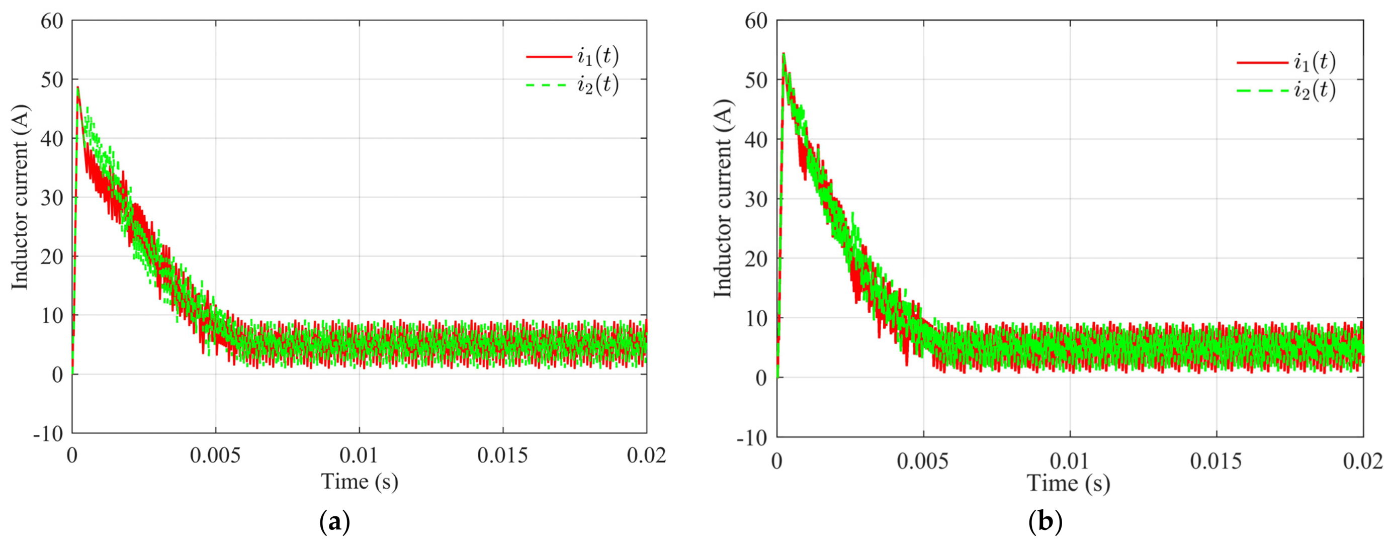
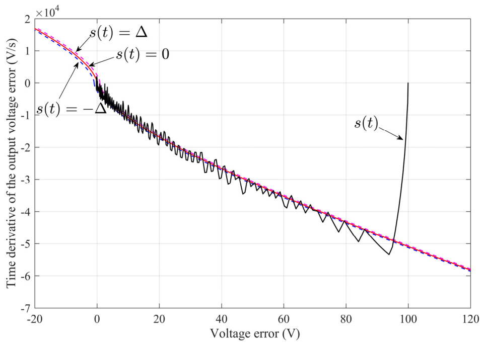
Figure 5 shows that both TSS-NTSMC and the proposed TSS-NFTSMC can converge to the reference voltage without overshoot, and TSS-NFTSMC exhibits faster convergence. This is because the nonsingular fast terminal sliding mode surface exhibits superior performance when the output voltage tracking error is large. Additionally, it possesses the finite-time convergence characteristic of the terminal attractor when the output voltage tracking error is small. Figure 5 shows the time taken for the two control schemes to reach 90 V, 95 V, and 99 V. Compared to TSS-NTSMC, TSS-NFTSMC reduces the time required to reach 90 V by 9.22%, the time required to reach 95 V by 8.33%, and the time required to reach 99 V by 6.26%. Figure 6 illustrates the inductor currents for both TSS-NTSMC and the proposed TSS-NFTSMC. The waveforms of i1(t) and i2(t)and for both control schemes are similar, indicating that the current equalization controller ensures a small difference between the two inductor currents, thereby preventing overcurrent issues in either phase. Figure 7 depicts the trajectory of the sliding variable. The sliding variable rapidly approaches the sliding surface and subsequently converges toward zero along the surface. It is worth noting that the sliding surface far from zero approximates a straight line, while the sliding surface near zero forms an arc. This is precisely the characteristic of a nonsingular terminal sliding surface. The farther the output voltage tracking error is from zero, the larger its time derivative becomes, accelerating the convergence speed of the output voltage. Even when the tracking error is near zero, its time derivative remains relatively large, which further aids in hastening the convergence of the tracking error.

4.2. Experimental Results

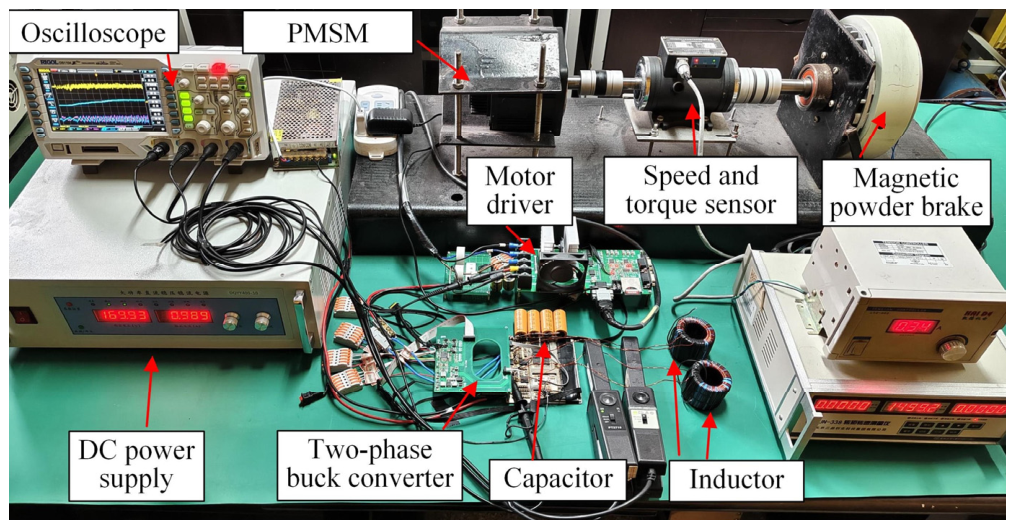
This part further validates the performance of the proposed control scheme using the experimental platform shown in Figure 8. Figure 8 includes the two-phase buck converter platform and the PMSM platform. The DC power supply provides input voltage to the two-phase buck converter. Simultaneously, the two-phase buck converter outputs a stable DC voltage. The output voltage of the two-phase buck converter supplies the DC bus of the PMSM driver. The microprocessor and power switch of the two-phase buck converter are STM32F405RGT6 and IPT111N20NFD, respectively. The control frequency of the controller is 50 kHz. Since the control frequency of the controller is 50 kHz, the maximum sampling frequency of the voltage sensor shall be greater than or equal to 50 kHz. Meanwhile, the microcontroller also needs to execute the control algorithm 50 thousand times per second, thus requiring a high-performance microcontroller. A high control frequency imposes stringent performance requirements on voltage sensors and microprocessors. Nevertheless, these specifications can be satisfied by mainstream commercial microprocessors and voltage sensors at present. The filter inductor and output capacitor of the two-phase buck converter are 460 μH and 2160 μF, respectively. The parameters of the PMSM are shown in Table 1. The PMSM, speed-torque sensor, and magnetic powder brake are connected in sequence. The magnetic powder brake can apply load torque to the PMSM. The reference speed of the PMSM is set to 1500 r/min. The motor driver can drive the PMSM to the reference speed.
Next, two tests with the PMSM load are conducted. The first test assesses the output voltage response of the two-phase buck converter when the PMSM is suddenly applied with load torque. The second test evaluates the output voltage response of the two-phase buck converter under input voltage fluctuations. In these two tests, the proposed TSS-NFTSMC is compared with TSS-NTSMC [43].
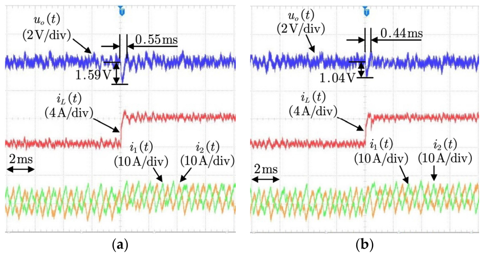
Test 1 (PMSM is applied with a torque load): When the PMSM is suddenly applied with load torque, the motor driver increases the output current to compensate for the load torque. Simultaneously, the bus current of the motor driver also increases. In this experiment, the bus current of the motor driver corresponds to the load current iL(t) of the two-phase buck converter. The input voltage of the two-phase buck converter is set to 150 V, and the reference value for the output voltage is designed to be 100 V. The output voltage, load current, and inductor currents of the two-phase buck converter under a sudden 2.1 Nm load applied to the PMSM are shown in Figure 9.
When the load current iL(t) suddenly increases, the output voltage of the proposed TSS-NFTSMC drops by 1.04 V. Subsequently, under the action of the TSS-NFTSMC, the output voltage rapidly recovers to its original value. Through comparison with the TSS-NTSMC, it can be concluded that the proposed TSS-NFTSMC exhibits greater robustness. The inductor currents i1(t) and i2(t) of the TSS-NFTSMC also increase to provide the large load current. Additionally, due to the operation of the current controller, the trends of inductor currents i1(t) and i2(t) become similar. The current controller prevents a situation where one inductor current is large while the other is small.
Test 2 (input voltage variation): This test verifies the output voltage response of the two-phase buck converter when the input voltage is suddenly changed while the PMSM is driving a load. First, a load torque of 2.1 Nm is applied to the PMSM. Subsequently, the input voltage of the two-phase buck converter is abruptly increased from 125 V to 175 V, representing a 40% increase. However, due to the regulation of the DC power supply, the actual input voltage will overshoot. The input voltage increases by a maximum of 68 V, representing a 54.4% increase. The reference voltage of the two-phase buck converter is set to 100 V.
The experimental results are shown in Figure 10. Under the action of the TSS-NFTSMC, the input voltage variation only causes the output voltage to rise by 0.32 V, which is an increase of 0.32%. Compared to the TSS-NTSMC, the proposed TSS-NFTSMC shows stronger robustness against input voltage fluctuations.

5. Conclusions

In this article, the TSS-NFTSMC is proposed for a two-phase buck converter. Thanks to the nonsingular fast terminal sliding surface, the output voltage error exhibits fast convergence rates both when the error is large and when it approaches zero. Furthermore, the three-switching-surface design allows the TSS-NFTSMC and current controller to directly determine the states of the power switches. Simulation and experimental results demonstrate that the proposed control scheme offers superior convergence speed and provides effective compensation for sudden changes in load current and input voltage.

Author Contributions

Conceptualization, J.X. and X.F.; methodology, J.X.; software, J.X.; validation, J.X. and X.F.; formal analysis, J.X.; investigation, J.X.; resources, J.X.; data curation, J.X.; writing—original draft preparation, J.X.; writing—review and editing, J.X.; visualization, J.X.; supervision, J.X.; project administration, X.F.; funding acquisition, X.F. All authors have read and agreed to the published version of the manuscript.

Funding

This research received no external funding.

Data Availability Statement

This article presents the original contributions of this research. For further inquiries, please contact the corresponding author.

Conflicts of Interest

The authors declare no conflicts of interest.

References

  1. Chen, Z.; Xiang, T.; Wu, Y.; Zhao, L.; Tang, X. Current Sharing Strategy of Three-Phase Series Capacitor Buck Converter for Wide Output Voltage Range Application. IEEE J. Emerg. Sel. Top. Power Electron. 2023, 11, 836–849. [Google Scholar] [CrossRef] [Scilit]
  2. Ning, G.; Chen, J.; Liu, Y.; Xu, G.; Xiong, W.; Su, M. Coupled-Inductor-Based Buck-Type Converter with Autonomous Voltage Balancing for Bipolar DC Microgrid. IEEE Trans. Power Electron. 2024, 39, 11937–11942. [Google Scholar] [CrossRef] [Scilit]
  3. Kang, Z.; Lin, X.; Liu, Z.; Shen, X.; Gao, Y.; Liu, J. Adaptive Generalized Super-Twisting Sliding Mode Control for PMSM Drives. IEEE Trans. Energy Convers. 2026, 41, 148–159. [Google Scholar] [CrossRef] [Scilit]
  4. Xu, R.; Liu, J.; Lin, X.; Liu, Z.; Yan, F.; Gao, Y. Autotuned Nonlinear Extended State Observer-Based Fixed-Time Control for Motor-Drive Servo Systems. IEEE Trans. Power Electron. 2025, 40, 14536–14546. [Google Scholar] [CrossRef] [Scilit]
  5. Shi, D.; Bodemann, K.; Wang, Y.; Xu, C.; Liu, L.; Feng, C. A Novel Nonsingular Fast Terminal Sliding Mode Control with Sliding Mode Disturbance Observer for Permanent Magnet Synchronous Motor Servo Control. Processes 2024, 12, 1986. [Google Scholar] [CrossRef] [Scilit]
  6. Ma, X.; Xu, Y.; Zhang, L.; Bai, J. Model-Free Generalized Super-Twisting Fast Terminal Sliding Mode Control for Permanent Magnet Synchronous Motors. Symmetry 2025, 17, 18. [Google Scholar] [CrossRef] [Scilit]
  7. Kandeel, Y.; O’Driscoll, S.; O’Mathúna, C.; Duffy, M. Optimum Phase Count in a 5.4-W Multiphase Buck Converter Based on Output Filter Component Energies. IEEE Trans. Power Electron. 2023, 38, 4909–4920. [Google Scholar] [CrossRef] [Scilit]
  8. Tang, R.; Song, H.; Lin, X.; Jiang, S.; Gao, X.; Liu, Z.; Liu, J. Prescribed-Time Synchronization of Second-Order Kuramoto Oscillators. IEEE Trans. Circuits Syst. II Express Br. 2026, 73, 453–457. [Google Scholar] [CrossRef] [Scilit]
  9. Zad, H.S.; Ulasyar, A.; Zohaib, A.; Khalid, S. Adaptive Observer-Based Robust Control of Mismatched Buck DC–DC Converters for Renewable Energy Applications. Eng. Proc. 2025, 111, 22. [Google Scholar]
  10. Ma, B.; Jiao, J.; Ye, Z. Adaptive Fast Integral Terminal Sliding Mode Control Strategy Based on Four-Switch Buck–Boost Converters. Energies 2024, 17, 3645. [Google Scholar] [CrossRef] [Scilit]
  11. Babes, B.; Mekhilef, S.; Boutaghane, A.; Rahmani, L. Fuzzy Approximation-Based Fractional-Order Nonsingular Terminal Sliding Mode Controller for DC–DC Buck Converters. IEEE Trans. Power Electron. 2022, 37, 2749–2760. [Google Scholar] [CrossRef] [Scilit]
  12. Campos, M.W.D.S.; Prado, E.M.; De Medeiros, R.L.; Fantesia, M.P.; De Oliveira, W.D.; Conceição, V.C.; Correa, I.V.; Dias, O.F.D.R.; Ayres, F.A.D.C. Development of a Hybrid Fractional-Order Fuzzy-PID Controller Applied to a DC-DC Buck Converter. IEEE Trans. Circuits Syst. II Express Br. 2025, 72, 1218–1222. [Google Scholar] [CrossRef] [Scilit]
  13. Kalvapalli, S.R.; Jeyasenthil, R.; Kobaku, T.; Siwakoti, Y. Quantitative Feedback Design Based Robust 2-DOF PID Control of Voltage Mode Controlled DC-DC Buck Converter with Unstructured Uncertainty and Sensor Noise Suppression. IEEE J. Emerg. Sel. Top. Ind. Electron. 2026, 7, 570–580. [Google Scholar] [CrossRef] [Scilit]
  14. He, W.; Namazi, M.M.; Guerrero, J.M. Adaptive Energy-Based Control for Buck Converter with a Class of Nonlinear Loads. IEEE Trans. Circuits Syst. II Express Briefs 2022, 69, 4869–4873. [Google Scholar] [CrossRef] [Scilit]
  15. Cheng, Y.; Du, H.; Yang, C.; Wang, Z.; Wang, J.; He, Y. Fast Adaptive Finite-Time Voltage Regulation Control Algorithm for a Buck Converter System. IEEE Trans. Circuits Syst. II Express Briefs 2017, 64, 1082–1086. [Google Scholar] [CrossRef] [Scilit]
  16. Alam, Z.; Roy, T.K.; Ghosh, S.K.; Mahmud, M.A. Control of DC–DC Buck Converters Using Robust Composite Backstepping and Integral Terminal Sliding Mode Approaches. IEEE J. Emerg. Sel. Top. Ind. Electron. 2023, 4, 866–877. [Google Scholar] [CrossRef] [Scilit]
  17. Martin, A.D.; Cano, J.M.; Silva, J.F.A.; Vázquez, J.R. Backstepping Control of Smart Grid-Connected Distributed Photovoltaic Power Supplies for Telecom Equipment. IEEE Trans. Energy Convers. 2015, 30, 1496–1504. [Google Scholar] [CrossRef] [Scilit]
  18. Liu, Y.; Mi, X.; Zhang, P.; Yang, Y.; Zheng, C.; Pei, Y. Hybrid Extended State Observer-Based Model-Free Predictive Control for Interleaved Buck Converter. IEEE Trans. Power Electron. 2026, 41, 1799–1810. [Google Scholar] [CrossRef] [Scilit]
  19. Yang, J.; Cui, H.; Li, S.; Zolotas, A. Optimized Active Disturbance Rejection Control for DC-DC Buck Converters with Uncertainties Using a Reduced-Order GPI Observer. IEEE Trans. Circuits Syst. I Regul. Pap. 2018, 65, 832–841. [Google Scholar] [CrossRef] [Scilit]
  20. Fei, J.; Jiang, D. Fuzzy Neural Network Sliding-Mode Controller for DC-DC Buck Converter. IEEE Internet Things J. 2024, 11, 31575–31586. [Google Scholar] [CrossRef] [Scilit]
  21. Fei, J.; Gong, X. Self-Organizing Fuzzy Neural Nonsingular Fast Terminal Sliding Mode Control of DC-DC Buck Converter. IEEE Trans. Circuits Syst. I Regul. Pap. 2024, 71, 4309–4322. [Google Scholar] [CrossRef] [Scilit]
  22. Wang, J.; Li, S.; Yang, J.; Wu, B.; Li, Q. Extended state observer based sliding mode control for PWM-based DC–DC buck power converter systems with mismatched disturbances. IET Control. Theory Appl. 2015, 9, 579–586. [Google Scholar] [CrossRef] [Scilit]
  23. Zheng, C.; Dragičević, T.; Zhang, J.; Chen, R.; Blaabjerg, F. Composite Robust Quasi-Sliding Mode Control of DC–DC Buck Converter with Constant Power Loads. IEEE J. Emerg. Sel. Top. Power Electron. 2021, 9, 1455–1464. [Google Scholar] [CrossRef] [Scilit]
  24. Wu, L.; Mei, P.; Lei, B.; Lin, Z. Dead-Beat Terminal Sliding Mode Control with Application to DC–DC Buck Converters. IEEE Trans. Circuits Syst. II Express Br. 2023, 70, 2470–2474. [Google Scholar] [CrossRef] [Scilit]
  25. Middlebrook, R.D.; Cuk, S. A general unified approach to modelling switching-converter power stages. In Proceedings of the 1976 IEEE Power Electronics Specialists Conference, Cleveland, OH, USA, 8–10 June 1976; IEEE: New York, NY, USA, 2015; pp. 18–34. [Google Scholar]
  26. Yue, X.; Wang, X.; Blaabjerg, F. Review of Small-Signal Modeling Methods Including Frequency-Coupling Dynamics of Power Converters. IEEE Trans. Power Electron. 2019, 34, 3313–3328. [Google Scholar] [CrossRef] [Scilit]
  27. Ling, R.; Maksimović, D.; Leyva, R. State-machine realization of second-order sliding-mode control for synchronous buck DC-DC converters. In Proceedings of the 2013 IEEE Energy Conversion Congress and Exposition (ECCE), Denver, CO, USA, 15–19 September 2013; IEEE: New York, NY, USA, 2013; pp. 125–132. [Google Scholar]
  28. Ling, R.; Maksimović, D.; Leyva, R. Second-Order Sliding-Mode Controlled Synchronous Buck DC–DC Converter. IEEE Trans. Power Electron. 2016, 31, 2539–2549. [Google Scholar] [CrossRef] [Scilit]
  29. Tan, S.-C.; Lai, Y.M.; Cheung, M.K.H.; Tse, C.K. On the Practical Design of a Sliding Mode Voltage Controlled Buck Converter. IEEE Trans. Power Electron. 2005, 20, 425–437. [Google Scholar] [CrossRef] [Scilit]
  30. Naik, B.; Mehta, A. Sliding mode controller with modified sliding function for DC–DC buck converter. ISA Trans. 2017, 70, 279–287. [Google Scholar] [CrossRef] [Scilit]
  31. Ding, S.; Zheng, W.X.; Sun, J.; Wang, J. Second-Order Sliding-Mode Controller Design and Its Implementation for Buck Converters. IEEE Trans. Ind. Inform. 2018, 14, 1990–2000. [Google Scholar] [CrossRef] [Scilit]
  32. Repecho, V.; Masclans, N.; Biel, D. A Comparative Study of Terminal and Conventional Sliding-Mode Startup Peak Current Controls for a Synchronous Buck Converter. IEEE J. Emerg. Sel. Top. Power Electron. 2021, 9, 197–205. [Google Scholar] [CrossRef] [Scilit]
  33. Zhang, L.; Wang, Z.; Li, S.; Ding, S.; Du, H. Universal finite-time observer based second-order sliding mode control for DC–DC buck converters with only output voltage measurement. J. Frankl. Inst. 2020, 357, 11863–11879. [Google Scholar] [CrossRef] [Scilit]
  34. Ramos, R.; Repecho, V.; Biel, D. Current-Limited Suboptimal Sliding Mode Control for Voltage-Regulated Synchronous Buck Converters. IEEE Trans. Power Electron. 2022, 37, 13081–13090. [Google Scholar] [CrossRef] [Scilit]
  35. Mao, G.; Zhou, G.; Zhao, H.; Gao, Y.; Kubulus, P.P.; Munk-Nielsen, S. Digital Average Current Predictive Control for Multiphase Interleaved DC–DC Converters. IEEE Trans. Circuits Syst. II Express Briefs 2023, 70, 4519–4523. [Google Scholar] [CrossRef] [Scilit]
  36. Ntogramatzidis, L.; Cuoghi, S.; Ricco, M.; Mandrioli, R.; Grandi, G. A Novel MIMO Control for Interleaved Buck Converters in EV DC Fast Charging Applications. IEEE Trans. Control. Syst. Technol. 2023, 31, 1892–1900. [Google Scholar] [CrossRef] [Scilit]
  37. Tao, L.; Wang, P.; Wang, Y.; Ma, X.; Cheng, P.; Zhao, D. Variable Structure ADRC-Based Control for Load-Side Buck Interface Converter: Formation, Analysis, and Verification. IEEE Trans. Ind. Electron. 2022, 69, 6236–6246. [Google Scholar] [CrossRef] [Scilit]
  38. Wang, Y.; Tao, L.; Wang, P.; Ma, X.; Cheng, P.; Zhao, D. Improved Linear ADRC for Hybrid Energy Storage Microgrid Output-Side Converter. IEEE Trans. Ind. Electron. 2022, 69, 9111–9120. [Google Scholar] [CrossRef] [Scilit]
  39. Kanzian, M.; Agostinelli, M.; Huemer, M. Digital hysteresis sliding mode control for interleaved DC–DC converters. Control Eng. Pract. 2019, 90, 148–159. [Google Scholar] [CrossRef] [Scilit]
  40. Lee, H.; Utkin, V.I.; Malinin, A. Chattering reduction using multiphase sliding mode control. Int. J. Control 2009, 82, 1720–1737. [Google Scholar] [CrossRef] [Scilit]
  41. Repecho, V.; Biel, D.; Ramos-Lara, R.; Vega, P.G. Fixed-Switching Frequency Interleaved Sliding Mode Eight-Phase Synchronous Buck Converter. IEEE Trans. Power Electron. 2018, 33, 676–688. [Google Scholar] [CrossRef] [Scilit]
  42. Repecho, V.; Biel, D.; Ramos-Lara, R. Robust ZAD Sliding Mode Control for an 8-Phase Step-Down Converter. IEEE Trans. Power Electron. 2020, 35, 2222–2232. [Google Scholar] [CrossRef] [Scilit]
  43. Xiong, J.; Fu, X. Three-Switching Surface Nonsingular Terminal Sliding Mode Control for Two-Phase Buck Converters with Load Variations and Uncertain System Parameters. IEEE Trans. Ind. Electron. 2025, 72, 887–897. [Google Scholar] [CrossRef] [Scilit]
  44. Minh Trieu, N.; Tan No, N.; Nguyen Vu, T.; Thinh, N.T. Chattering-Free PID-Nested Nonsingular Terminal Sliding Mode Controller Design for Electrical Servo Drives. Mathematics 2025, 13, 1197. [Google Scholar] [CrossRef] [Scilit]
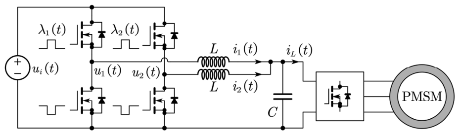
Figure 1. Two-phase buck converter powering DC bus of PMSM Drives.
Electronics 15 02024 g001
Figure 2. Control diagram of the proposed control scheme.
Electronics 15 02024 g002
Figure 3. Comparison of the nonsingular terminal sliding surface and the nonsingular fast terminal sliding surface.
Electronics 15 02024 g003
Figure 4. Phase plot of TSS-NFTSMC.
Electronics 15 02024 g004
Figure 5. Step response of the output voltage under resistive load conditions.
Electronics 15 02024 g005
Figure 6. Inductive currents in the first and second phases under resistive load conditions. (a) Inductive currents when using TSS-NTSMC; (b) inductive currents when using TSS-NFTSMC.
Electronics 15 02024 g006
Figure 7. Phase plot of the two-phase buck converter control system.
Electronics 15 02024 g007
Figure 8. Two-phase buck converter experimental platform with PMSM load.
Electronics 15 02024 g008
Figure 9. Output voltage, load current, and inductor currents of two-phase buck converter un-der the condition that PMSM is applied with 2.1 Nm load. (a) Experimental results for the TSS-NTSMC when a 2.1 Nm load is suddenly applied to the motor; (b) experimental results for the TSS-NFTSMC when a 2.1 Nm load is suddenly applied to the motor.
Electronics 15 02024 g009
Figure 10. Output voltage of the two-phase buck converter when the input voltage is suddenly changed. (a) Experimental results for the TSS-NTSMC when the input voltage suddenly increases; (b) experimental results for the TSS-NFTSMC when the input voltage suddenly increases.
Electronics 15 02024 g010
Table 1. Parameters of the PMSM.
ParametersValueParametersValue
d-axis inductance2.95 mHq-axis inductance2.95 mH
Rated speed1500 r/minStator resistance0.59 Ω
Rated power750 WStator flux linkage91.45 mWb
Rated torque4.78 NmViscous friction coefficient0.005 Nms/rad
Pole pairs5Moment of total inertia0.0108 kgm2
Disclaimer/Publisher’s Note: The statements, opinions and data contained in all publications are solely those of the individual author(s) and contributor(s) and not of MDPI and/or the editor(s). MDPI and/or the editor(s) disclaim responsibility for any injury to people or property resulting from any ideas, methods, instructions or products referred to in the content.