Article

Comprehensive Power Regulation of a Novel Shared Energy Storage Considering Demand-Side Response for Multi-Scenario Bipolar DC Microgrid

1
CHN Energy (Gonghe) Renewable Energy Development Co., Ltd., Hainan 813000, China
2
National Institute of Clean-and-Low-Carbon Energy, Beijing 102211, China
3
School of Automation Engineering, University of Electronic Science and Technology of China, Chengdu 611756, China
*
Author to whom correspondence should be addressed.
Electronics 2025, 14(9), 1866; https://doi.org/10.3390/electronics14091866 (registering DOI)
Submission received: 17 March 2025 / Revised: 21 April 2025 / Accepted: 27 April 2025 / Published: 3 May 2025
(This article belongs to the Special Issue Innovations in Intelligent Microgrid Operation and Control)

Abstract

:
In order to improve the ability to suppress unbalanced voltage in bipolar DC microgrids, a comprehensive power regulation control of a novel shared energy storage system is proposed for a multi-scenario bipolar DC microgrid. The novel shared energy storage system is composed of an electric spring (ES) with a full-bridge DC/DC converter and non-critical load (NCL) in series, considering demand-side response. The proposed comprehensive power regulation control can enable the bipolar DC microgrid to deal with various scenarios. When operating in stand-alone mode, the unbalanced voltage caused by greater unbalanced power can still be suppressed under the proposed control of the shared energy storage. In case of distributed energy storage (DES) failure on the source side, the shared energy storage can realize DC voltage regulation and maintain system operation by reducing NCL power. In grid-connected operation, the shared energy storage can actively cooperate with the power dispatching of the utility grid for storage reduction of DES on the source side. Thus, the reliability and resilience of the bipolar microgrid have been improved. Finally, to verify the effectiveness of the proposed control strategy, hardware-in-the-loop experimental results are presented in this paper.

1. Introduction

Recently, DC loads such as electronic equipment, electric vehicles, and DC motors, have been widely used in daily life. In addition, due to not suffering from the issues of harmonics, reactive power loss, and phase synchronization, DC microgrids are of great significance to renewable energy consumption, and have received much attention [1,2,3]. According to the form of power distribution and the number of power supply buses, DC microgrids are classified into unipolar and bipolar. Bipolar DC microgrids with three-wire structures (positive bus, negative bus, and neutral bus) not only inherit the general advantages of unipolar DC microgrids, but also are superior in terms of having different voltage levels, further improving the flexibility of the DC power supply [4,5,6].
During the operation of a bipolar DC microgrid, unbalanced voltage between the positive and negative poles is a problem worthy of attention. Unbalanced current caused by the power difference will increase the power loss of the network. Moreover, the current in the neutral bus will also bring about load voltage deviation, deteriorating the quality of the power supply [7,8]. Therefore, it is necessary to suppress unbalanced voltage to ensure the efficient and reliable operation of bipolar DC microgrids.
In previous studies on bipolar DC microgrids, unbalanced voltage and power regulation have usually been accomplished by adopting a splitting capacitor-based converter with balanced voltage control for distributed energy storage (DES) on the source side [9,10]. Aiming at splitting capacitor-based bipolar DC microgrids, scholars mainly focus on the converter topology and control method. For the unbalanced voltage suppression control method of a traditional three-level converter, Refs. [11,12,13] studied a three-level buck converter and boost converter, and proposed corresponding control methods for voltage regulation; while [14] focused on model predictive control (MPC) of a three-level bidirectional converter (T-LBC) to realize bidirectional power flow and voltage balance in a bipolar DC microgrid. However, the topologies and control methods mentioned above use DES to achieve power regulation (e.g., suppress unbalanced voltage and power dispatching) of a bipolar DC microgrid only from the perspective of the source side, without considering demand-side response.
In fact, distributed resources such as household energy storage and electric vehicles near the demand side have bidirectional regulation functions, which can flexibly switch roles between being power producers and consumers to achieve clean, low-carbon, safe, and efficient development of power systems [15,16,17]. In recent years, the concept of shared energy storage has been proposed and rapidly developed. Shared energy storage can effectively reduce operating costs, promote on-site consumption of renewable energy, and achieve power/frequency regulation by utilizing the complementarity of DES among different users; Refs. [18,19,20,21,22] proposed shared energy storage operation management frameworks based on capacity allocation and energy interaction. Based on shared energy storage devices, Ref. [23] proposed an energy capacity trading strategy to minimize the operating costs for microgrids; Ref. [21] studied a day-ahead scheduling model of a regional integrated energy system considering sharing energy storage equipment utilizing cooperative game theory. However, the above studies only involve optimizing the operation and capacity configuration of shared energy storage to achieve long-term economic benefits, with little consideration given to the participation of shared energy storage in short-term power regulation under changeable demand-side response.
Aiming at the control of shared energy storage considering demand-side response, using a DC electric spring (ES) to eliminate voltage imbalance has emerged as a potential method [24]. By dividing the load into critical load (CL) and non-critical load (NCL), a DC ES can take advantage of the loose voltage or power adjustment range of the NCL to obtain flexible regulation ability. Meanwhile the CL and NCL are both in operation. Up till now, DC ESs have been studied in the fields of stabilizing DC bus voltage [25,26], restraining harmonics [27,28], and improving system inertia; Ref. [29] proposed a distributed control method based on MPC for both improving system inertia and reducing voltage deviation; Ref. [30] studied a DC ES and its functionalities of DC bus regulation and fault-ride through support; Ref. [31] utilized a DC ES to reduce the power loss on the line resistance in a DC microgrid. However, the above studies only aimed to improve the performance of DC microgrids in islanded operation.
Motivated by the above, this paper establishes a novel shared energy storage system based on a DC ES configuration with the combination of economic control in grid-connected operation and performance improvement in islanded operation. The proposed comprehensive power regulation method can not only improve the ability of unbalanced voltage suppression and realize voltage support in the case of DES failure, but also adjust power consumption according to the power dispatching command.

2. Analysis of Studied Bipolar DC Microgrid Equipped with a Novel Shared Storage System

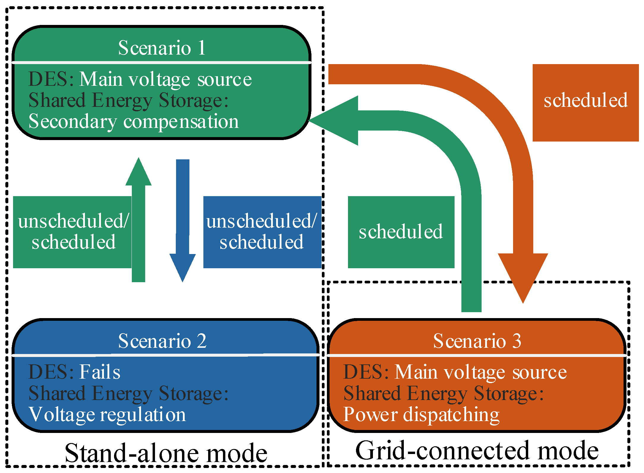
2.1. Overview and Operation Principle

Figure 1 shows the configuration of the studied bipolar DC microgrid with three DC buses, namely, the positive bus (P), negative bus (N), and neutral bus (0), which is equipped with a novel shared storage system. A cluster of distributed generators (DGs) is installed on the power supply side. The generated power can be fed with ±0.5 VDC (P−0 and 0-N) and VDC, where VDC is the nominal value of the P-N bus voltage. DES is normally responsible for both the bus voltage regulation and unbalanced voltage suppression through a T-LBC. On the demand side, except for the conventional loads composed of the constant power load (CPL) and resistive load, ESs with the structure of NCLs in series are combined to inform the shared energy storage system for both the positive and negative poles, allowing flexible power consumption. This novel shared energy storage system consisting of an ES and series-connected NCLs can achieve charging and discharging by making the NCLs bear voltage deviations with full consideration of users’ demands.
The bipolar DC microgrid with novel shared energy storage is generally able to operate in stand-alone or grid-connected mode with the disconnection or connection of the utility grid. For the DES control system, a droop control method with voltage balance of the neutral bus is adopted to manage the parallel operations of the DGs, which has been well explored in previous research work. Thus, the proposed control strategy is targeted at the shared energy storage on the demand side, which can adapt to both stand-alone and grid-connected operation modes. Based on the system structure in Figure 1, the proposed comprehensive power-regulation-controlled shared energy storage system can consequently work in three operation modes in response to the specific scenarios illustrated in Figure 2.
(1)
Secondary compensation mode: In scenario 1, when DES exists, the shared energy storage is controlled to realize secondary compensation for eliminating the bus voltage deviation caused by the droop characteristic and improving the ability to suppress unbalanced voltage.
(2)
Voltage regulation mode: In scenario 2, when DES fails, the shared energy storage is controlled as two DC voltage sources, regulating the bus voltage and maintaining the power balance between the positive and negative poles by adjusting the power consumption of the NCL.
(3)
Power dispatching mode: In scenario 3, when the bipolar DC microgrid operates in grid-connected mode, the shared energy storage is controlled as the current source, managing the part of the power flow between the microgrid and the utility grid.

2.2. Realization of Secondary Compensation

In order to further analyze the voltage imbalance suppression ability, the bipolar DC microgrid with the novel shared energy storage shown in Figure 1 was simplified, as demonstrated in Figure 3. Since a DG controlled by MPPT can be regarded as a power source with changing power in real time, it can be represented by the negative of the CPL power. Define P1,2 = PCPL1,2PRES1,2, then P1,2 > 0 indicates that the power generated by the DGs is less than the power consumed by the loads. On the contrary, P1,2 < 0 means that the supplied power is more than load power. The subscripts 1 and 2 represent the power between P-0 and 0-N, respectively.
A CPL can be simulated by the controlled current source and resistance connected in parallel expressed in (1).
I CPL , i = 2 P CPL , i V 0 P CPL , i V 0 2 V CPL , i     ( i = 1 , 2 )
where ICPL,i is the current absorbed by CPLi, VCPL,i is the voltage across CPLi, PCPL,i is the power consumed by CPLi, V0 is the voltage of the normal operation point, and V0 = 0.5 VDC.
In a shared energy storage system, an ES with the structure of an NCL in series can be equivalent to a controlled voltage source and resistance connected in series. The relationship of voltage, current, and power is described in (2).
I N C L , i = V N C L , i R N C L , i V i = V N C L , i + V E S , i                       ( i = 1 , 2 ) P SL , i = V N C L , i 2 + V N C L , i V E S , i R N C L , i
where VNCL,i, INCL,i, and RNCL,i are the voltage, current, and resistance of NCLi. PNCL,i is the sum of the power of NCLi and ESi.
According to the KCL law in Figure 3 and the CPL equivalent model in (1), the relationship between the currents in the positive bus I1, negative bus I2, and neutral bus I0 can be obtained as in (3) without considering shared energy storage.
I 0 = I 1 I 2 = 2 P 1 V 0 P 1 V 0 2 V 1 2 P 2 V 0 + P 2 V 0 2 V 2
where P1,2 is the net power consumed after equivalence of the RES and CPL. V1 and V2 are the voltages of the positive and negative poles. The subscripts 1, 2, and 0 denote the positive, negative, and neutral buses, respectively.
The neutral bus current of the T-LBC can be calculated by (4):
I M = I 0 + C 1 d V 1 d t C 2 d V 2 d t
where IM is the output current in the neutral line of the T-LBC. C1 and C2 are the output capacitance.
When C1 and C2 are designed to be the same and equal to C, (5) can be deduced by integrating (4).
V 1 V 2 = 1 C 0 T s ( I M I 0 ) d t
Because the value of I0 is related to the difference of P1 and P2, V1 = V2 can only be realized by controlling IM. According to (4), V1 = V2 will cause IM = I0. Using the relationship of V1 = V2 = V0 = 0.5 VDC, the following can be obtained.
I M = I 0 = ( P 1 P 2 ) V 0 = 2 ( P 1 P 2 ) V DC
Substituting the relationship between the input and output currents of the T-LBC, shown as IM ≤ (1 − D)IL, into (6), the imbalance in power can be further obtained.
P 1 P 2 ( 1 D ) I L V DC 2
where D and IL are the duty cycle and input current of the T-LBC.
Therefore, in the bipolar DC microgrid without shared energy storage, only when the imbalance power meets (7) can neutral-point voltage balance control be achieved by the T-LBC.
After considering shared energy storage, combining (2) and (3), I0, I1, and I2 are changed into the following.
I 0 = I 1 I 2 I 1 = 2 P 1 V 0 P 1 V 0 2 V 1 + V 1 V E S 1 R N C L 1 I 2 = 2 P 2 V 0 P 2 V 0 2 V 2 + V 2 V E S 2 R N C L 2
According to (8), and further assuming RNCL,1 = RNCL,2, (4) and (7) can be rewritten as (9) and (10).
I M = 2 ( P 1 P 2 ) V DC + V E S 2 V E S 1 R N C L
P 1 P 2 ( 1 D ) I L V DC 2 + ( V E S 1 V E S 2 ) V DC 2 R N C L
where VES1VES2 can be controlled to be larger than 0.
Therefore, after equipping shared energy storage in the bipolar DC microgrid, the value of unbalanced power can be greater than that in (7). That is, the system has a stronger ability to suppress unbalanced voltage.

2.3. Regulation of Bus Voltage as Voltage Source

When DES in the system fails and exits the operation, shared energy storage is controlled as follows.
(1)
ES1 and ES2 can keep V1 and V2 running at the rated voltage point V0 by controlling VES1 and VES2. Therefore, the stability of the bus voltage within a certain range is maintained.
(2)
Coordinating PSL1 and PSL2 can ensure P1 + PSL1 = P2 + PSL2. Thus, unbalanced voltage control is achieved.

2.4. Ability of Power Dispatching

Define that PG is the interactive power between the bipolar DC microgrid and the grid. It is worth noting that it is assumed that PG is a known parameter obtained by upper-level optimization. How factors such as user behavior and electricity prices affect PG is not considered in this paper. PG > 0 means there is power transmission from the bipolar DC microgrid to the grid, while PG < 0 indicates that the bipolar DC microgrid absorbs power from the grid. Then, the load power consumption of the whole system can be calculated by P1 + PSL1 + P2 + PSL2. Assuming that the power transmitted by DES through the T-LBC is PS, PS > 0 means discharging of DES, otherwise the DES is charging. Thus, according to the V-I relationship of the series ESs in (2), PG can be described by (11).
P G = P S ( P 1 + P 2 + P S L 1 + P S L 2 )   = P S P 1 P 2 V DC 2 R N C L ( 2 V DC V E S 1 V E S 2 )
It can be seen from (11) that PG can be adjusted by controlling VES1 and VES2, which means power consumed by NCLs can be dispatched by controlling the ES according to the dispatching command PG. Although the efficiency of the NCLs will be affected, the bus voltage of the system can be compensated and economic power dispatching can be achieved by increasing or decreasing the power consumption of the NCLs.

3. Proposed Comprehensive Power Regulation Control Strategy

The comprehensive power regulation control strategy proposed in this paper is divided into two parts: the voltage support of shared energy storage in stand-alone operation mode, and the power dispatching in grid-connected operation mode. In this section, these two parts are described in detail. The topology of shared energy storage is composed of an ES with full-bridge DC/DC converter and NCLs connected in series, as shown in Figure 4.
We take one shared energy storage system as an example to explain the control strategy in detail; the control system of another one can be designed in the same way. Since DES adopts droop control with voltage balance control for the neutral bus, the load voltage VDC has a deviation due to the droop characteristics. Thus, there is also a voltage drop in V1 and V2. In order to compensate for the voltage deviation, the ES with full-bridge DC/DC converter adopts voltage–current double-loop control, as shown in (12).
V 1 ref = V 0   I E S 1 ref = ( V 1 ref V 1 ) * G V 1 d 1 = ( I E S 1 ref I E S 1 ) * G I 1
where GV1 and GI1 are the transfer functions of the PI controller in the voltage loop and current loop, respectively. d1 is the duty cycle of IGBT (Insulated Gate Bipolar Transistor); T11/T14, and T12/T14 are controlled by (1 − d1). V 1 ref and I E S 1 ref are the reference values of the voltage outer loop and current inner loop.

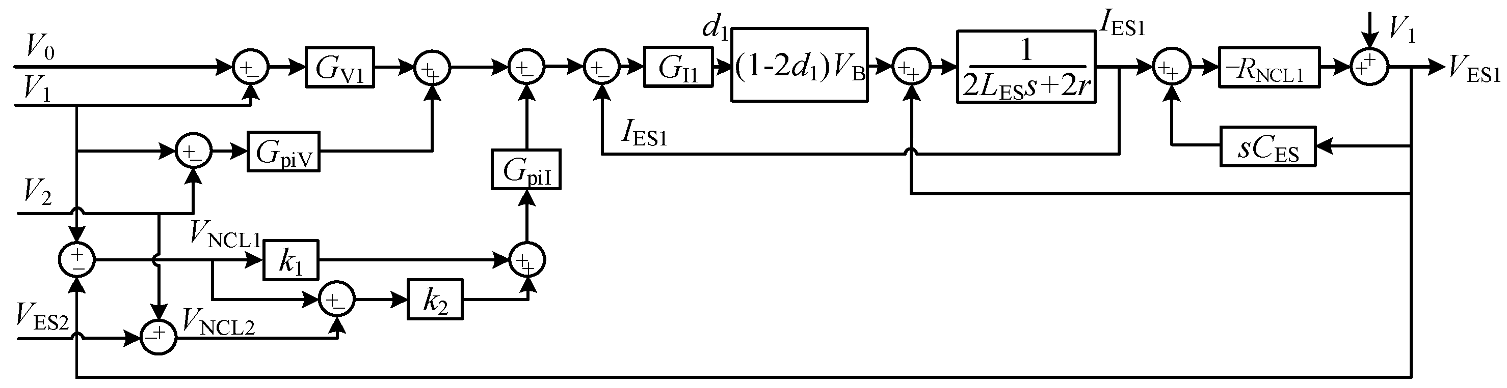
3.1. Design of Unbalanced Voltage Suppression Control with Voltage Support in Stand-Alone Mode

When the bipolar DC microgrid operates in stand-alone mode, shared energy storage needs to further improve the ability of unbalanced voltage suppression on the basis of bus voltage deviation compensation. Therefore, by adding the unbalanced voltage correction to (12), the ES can compensate the voltage imbalance, as shown in (13).
Δ V 1 = ( V 1 V 1 + V 2 2 ) * G piV
where G V 1 is the transfer function of the PI controller with the objective of enforcing zero (V1V2), achieving voltage balance between V1 and V2 by adding the imbalance correction ΔV1 to the bus voltage reference.
On the other hand, (13) is also critical for enabling the bus voltage regulation capability in the event of DES failure. At this moment, due to the constant voltage control of the ES in (12), as long as the power balance is maintained, the system will not collapse when DES fails. The NCL power can be either decreased or increased by controlling the ES voltage, thus the power provided/absorbed by the failed DES before can be balanced by the NCL.

3.2. Design of Unbalanced Voltage Suppression Control with Power Dispatching in Grid-Connected Mode

In grid-connected operation mode, the power command PG on the inverter is sent from the dispatching center. In order to cooperate with the power dispatching of the utility grid, power consumed by NCLs should be adjusted according to PG. Different from the condition in stand-alone operation mode, load power should be reduced when PG > 0, which indicates the utility grid requests power from the microgrid. When the utility grid needs to transmit power to the microgrid, that is, PG < 0, the NCL needs to increase the consumed power, improving the power transmission capacity of the microgrid. Considering that the ES adopts constant voltage control, the change in power can only be obtained by correcting the reference current of the NCL. Therefore, the current correction can be calculated by the following.
Δ I 1 d = ( V N C L 1 min V N C L 1 ) * G piI   P G > 0   Δ I 1 i = ( V N C L 1 max V N C L 1 ) * G piI   P G < 0
where V N C L 1 min and V N C L 1 max are the allowable minimum and maximum voltages of NCL1. G piI is the transfer function of the PI controller with the objective of enforcing zero ( V N C L 1 min V N C L 1 ) or ( V N C L 1 max VNCL1).
In order to further deal with the case of using shared energy storage to improve the unbalanced voltage suppression capability, a power imbalance correction is carried out for the current correction according to the different consumed powers of PSL1 and PSL2. Therefore, the current correction shown in (14) is rewritten as (15).
Δ I 1 d = G piI * ( V N C L 1 min V N C L 1 + max { ( V N C L 1 V N C L 2 ) , 0 } )   P G > 0 Δ I 1 i = G piI * ( V N C L 1 max V N C L 1 + min { ( V N C L 1 V N C L 2 ) , 0 } )   P G < 0
where max {( V N C L 1 V N C L 2 ), 0} stands for the larger value between ( V N C L 1 V N C L 2 ) and 0, and min {( V N C L 1 V N C L 2 ), 0} represents the smaller value between ( V N C L 1 V N C L 2 ) and 0.
Equation (15) means that when PG > 0, the shared energy storage with less total power between PSL1 and PSL2 is limited to the allowable minimum power value of the NCL, and the other one is adjusted according to the voltage balance. Similarly, when PG < 0, the shared energy storage with larger power between PSL1 and PSL2 is set to the allowable NCL maximum power. According to the above analysis, the current reference value of NCL1 in power dispatching mode is calculated as follows:
Δ I N C L 1 = Δ I 1 d ,   P G > 0 0 ,       P G = 0 Δ I 1 i ,   P G < 0
I E S 1 ref = ( V 1 ref V 1 ) * G V 1 + Δ V 1 Δ I N C L 1
Thus, power dispatching can be achieved by using (16) and (17). It is worth mentioning that the power dispatching function in grid-connected mode can be enabled by a variable δ. When PG is equal to 0, δ is equal to 0. Otherwise, δ is equal to 1. As shown in Figure 4, the blue box is controlled by δ, marked in red.

4. Stability Analysis

Since the proposed control strategy is aimed at the full-bridge DC/DC converter of the ES in the shared energy storage, the dynamics of the voltage outer loop and current inner loop can be decoupled for stability analysis. A stability analysis of a conventional voltage-controlled full-bridge DC/DC has been presented in [31]. The analysis for the proposed unbalanced voltage suppression-controlled ESs in the bipolar DC microgrid can be carried out based on it. Figure 5 shows the equivalent control diagram of the autonomous controlled ES1, where the output voltage and current can be obtained from (18), and the current relationship between ES1 and ES2 is described in (19).
V ˙ E S 1 = V E S 1 R N C L 1 C E S 1 I E S 1 C E S 1 + V 1 R N C L 1 C E S 1 I ˙ E S 1 = V E S 1 2 L E S 1 r L E S 1 I E S 1 Δ d 2 L E S 1 V B 1
where r is the equivalent series resistor of inductor LES1. Δd is the difference in the duty ratios between T11 and T13, calculated as Δd = 2d1 − 1.
C D V ˙ 1 = V S 1 V 1 r d P 1 V 1 I N C L 1 C D V ˙ 2 = V S 2 V 2 r d P 2 V 2 I N C L 2
The state-space model of unbalanced voltage correction and NCL current correction can be obtained by introducing intermediate variables φpiV and
k iiV 1 φ ˙ piV 1 = V 1 V 2 2 k iiI 1 φ ˙ piI 1 = k 1 V N C L 1 + k 2 ( V N C L 1 V N C L 2 )
The state-space model of the voltage loop and current loop can also be obtained in a similar way.
k iV 1 φ ˙ V 1 = V 0 V k iI 1 φ ˙ I 1 = k pV 1 ( V 0 V 1 ) + φ V 1 + k piV 1 ( V 1 V 2 ) / 2 + φ piV 1 + k piI 1 [ ( k 1 k 2 ) V N C L 1 k 2 V N C L 2 ] + φ piI 1
The state space model of ES1 and its control system can be expressed in the following by integrating (18)–(21) and combining the voltage current relationship shown in (2).
X ˙ 1 = A 1 X 1 X 1 = [ V 1 , V E S 1 , I E S 1 , φ piV , φ piI , φ V 1 , φ I 1 ] T
Thus, duty cycle d1 can be obtained through (23).
d 1 = k pI 1 k iI 1 φ ˙ I 1 + φ I 1
In the same way, the state-space model of ES2 can be obtained, which will not be repeated here. Therefore, based on the current relationship shown in (19), the state-space model of Figure 4 can be expressed as X ˙ = A X , where X = [ V 1 , 2 , V E S 1 , 2 , I E S 1 , 2 , φ piV 1 , 2 , φ piI 1 , 2 , φ V 1 , 2 , φ I 1 , 2 ] T .
With the state-space model of the whole system presented in (4), the stability analysis of unbalanced voltage suppression-controlled ESs can be developed with the parameters listed in Table 1. In order to analyze the stability under different unbalanced load power and dispatching power from the utility grid, the root locus plot considering changes in Δ P = | P 1 P 2 | and PG is shown in Figure 6.
It can be seen from Figure 6a, with the increase in ΔP, the eigenvalues λ1,2, λ4, and λ7,8 are vulnerable to being influenced. However, although λ7,8 move towards the unstable area, all the eigenvalues are located in the left half-plane with the range of 0~5000, which indicates the system is stable.
When PG increases, the small-signal stability is also changed, especially λ3,4 and λ9,10, which, respectively, move towards the right half-plane and move far away from the real axis, as shown in Figure 6b. A stability analysis of the proposed control in the condition where PG = 0, k1, k2, k3, and k4 are set to 0 in stand-alone operation is also presented.

5. Results and Discussion

To verify the effectiveness of the proposed control strategy, hardware-in-the-loop experiments based on the OPAL-RT real-time simulator and MATLAB/Simulink 2020a simulation environment were developed, as presented in Figure 7. The control systems of the shared energy storage were implemented by a DSP(TMS320F28335) controller, while the mathematic model of the system, including the loads shown in Equation (1), were established by OPAL-RT based on the MATLAB/Simulink modeling environment. The DSP controller and OPAL-RT were connected through built-in input/output modules, while the host computer and OPAL-RT were connected through TCP/IP. The effect of the communication delay is not considered in this paper. The basic parameters of the tested bipolar DC microgrid shown in Figure 3 can be seen in Table 2, which shows the power scale of the studied system and the limit values of both power generation and power consumption.
Three cases with different scenarios for changes in stand-alone mode and grid-connected mode were tested. With the controller parameters given in Table 1, the power of the NCLs, CPLs, and DES of the studied system are observed to explain the control performance, and also the voltages of the positive and negative poles.

5.1. Case 1: Secondary Compensation Mode

In case 1, the performance of shared energy storage operating in secondary compensation mode with the change in CPLs is studied and the experimental results are presented in Figure 8. The results without shared energy storage are also presented. Initially, P1 and P2 are −2.5 kW and −4 kW, respectively. Here, the negatives of P1 and P2 mean that the power generated by the DGs is greater than that consumed by the CPLs. The power difference between the positive and negative poles can be calculated by ΔP = |P1P2|. In this condition, the bipolar DC microgrid without shared energy storage can also regulate the DC bus voltage and suppress unbalanced voltage through the control of the T-LBC, as shown in Figure 8b before t = 2 s. However, there are still voltage deviations in V1 and V2. Fortunately, this drawback is solved when the bipolar DC microgrid is equipped with shared energy storage, as shown in Figure 8a. It can be concluded that with the proposed control of shared energy storage, the DC bus voltage deviation caused by droop control of the T-LBC has been reduced from 2.67% to 0.01%.
Power change happens at t = 2 s. P1 suddenly changes from −2.5 kW to 0 kW. ΔP subsequently increases from 1.5 kW to 4 kW, which has gone beyond the unbalanced voltage suppression ability of the T-LBC. Thus, in Figure 8b, the voltage difference occurs after t = 2 s, where V1 = 138 V and V2 = 146 V. While in Figure 8a, with the proposed control of shared energy storage, the voltage imbalance has been well eliminated for the different power consumed in NCL1 and NCL2. The difference between V1 and V2 has been reduced from 5.3% to around 0%.

5.2. Case 2: Secondary Compensation Mode to Voltage Regulation Mode

Case 2 demonstrates the mode switch from secondary compensation to voltage regulation mode in stand-alone operation. The experimental results are shown in Figure 9. The initial conditions are the same as in case 1. At t = 2 s, the T-LBC fails and disconnects from the DC bus. As shown in Figure 10, the shortage power caused by the failing of the T-LBC is compensated by further reducing the power consumed by NCL1, from 4.5 kW to 3.2 kW, and by NCL2, from 2.75 kW to 2 kW. Consequently, the DC bus voltages of the positive and negative poles are regulated and balanced by the shared energy storage, as shown in Figure 10, where V1 = V2 ≈ 150 V. Thus, the effectiveness of the proposed control strategy from secondary compensation mode to voltage regulation mode in stand-alone mode has been verified.

5.3. Case 3: Secondary Compensation Mode to Power Dispatching Mode

In case 3, the performance of the studied system operating from secondary compensation mode to power dispatching mode is explored, and Figure 11 and Figure 12 show the experimental results. The initial conditions are the same as in case 1 before t = 2 s, as shown in Figure 11. The bipolar DC microgrid is connected with the utility grid at t = 2 s. With the condition of PG = 3 kW, NCLs reduce its power consumption to enable the microgrid output a larger PG. Thus, DES only needs to output 1.9 kW to smooth the power imbalance. However, if the NCL does not reduce its power consumption, DES will output a power greater than 3 kW, which has already exceeded the maximum output power of DES. Therefore, the bipolar DC microgrid cannot meet the power dispatching of the utility grid without reducing NCL power in some conditions.
Furthermore, the performance of the power dispatching mode with PG change in grid-connected operation is also presented between t = 2 and 6 s. When t = 4 s, the dispatching power PG changes from 3 kW to −4 kW, which means the utility grid transmits power to the bipolar DC microgrid. The consumed power of the NCLs increases to the maximum load power P N C L 1 m a x and P N C L 2 m a x . With the condition of PNCL,1 = 7.2 kW and PNCL,2 = 4.3 kW, DES only needs to output power of 1 kW through the T-LBC.
During the operation of mode transferring and the change in PG, the DC voltage of V1 and V2 can be well maintained to be balanced and stable, as shown in Figure 12. The effectiveness of the proposed control strategy from secondary compensation mode in stand-alone operation to power dispatching mode in grid-connected operation has been verified.
In order to reflect the advantages of the power dispatching mode of the ESs, Table 3 shows the NCL consumption power and DES output power under the conditions of actively adjusting power and non-regulation power, respectively.
It can be seen from Table 3 that when PG > 0, NCLs can reduce the power consumption to enable DES to output less power. So, the capacity of DES can be reduced and the bipolar microgrid can output more PG. Similarly, when PG < 0, NCLs can reduce the input power of DES by increasing the power consumption, so as to make the microgrid have the ability to absorb greater PG.

6. Conclusions

In this paper, comprehensive power regulation control of shared energy storage with both voltage support and power dispatching for a multi-scenario bipolar DC microgrid is proposed. The proposed control is targeted at ensuring the performance of the bipolar DC microgrid in different conditions, which are stand-alone operation, DES failure condition, and grid-connected operation. In this way, the voltage deviation is reduced by about 2.67% in stand-alone operation, and DES achieves a lower power in power dispatching mode than in grid-connected operation. Furthermore, when DES fails, DC voltage can still be regulated by decreasing the power consumption of the shared energy storage. With the proposed control, the reliability and resilience of the bipolar DC microgrid are both improved. Then, the system’s stability under proposed control is analyzed based on small-signal modeling, and the HIL experimental results for different operating conditions are carried out to verify the effectiveness of the proposed control.

Author Contributions

Conceptualization, G.L. and B.Z.; methodology, X.M.; Validation, X.J. and H.Y.; writing-original draft preparation, H.Y.; writing-review and editing, G.L., B.Z., X.M. and X.J. All authors have read and agreed to the published version of the manuscript.

Funding

This paper was supported by Research and Technology Project for 100 MW High Voltage Energy Storage System (Grant Nos. E565400011).

Data Availability Statement

The original contributions presented in this study are included in the article. Further inquiries can be directed to the corresponding author.

Conflicts of Interest

Author Gongqiang Li, Bin Zhao and Xiaoqiang Ma were employed by the company CHN Energy (Gonghe) Renewable Energy Development Co., Ltd., Author Xiaofan Ji were employed by the company National Institute of Clean-and-Low-Carbon Energy. The remaining authors declare that the research was conducted in the absence of any commercial or financial relationships that could be construed as a potential conflict of interest.

References

  1. Lotfi, H.; Khodaei, A. Ac versus dc microgrid planning. IEEE Trans. Smart Grid 2015, 8, 296–304. [Google Scholar] [CrossRef]
  2. Han, Y.; Zhang, G.; Li, Q.; You, Z.; Chen, W.; Liu, H. Hierarchical energy management for pv/hydrogen/battery island dc microgrid. Int. J. Hydrogen Energy 2019, 44, 5507–5516. [Google Scholar] [CrossRef]
  3. Li, X.; Jiang, W.; Wang, J.; Wang, P.; Wu, X. An autonomous control scheme of global smooth transitions for bidirectional dc-dc converter in dc microgrid. IEEE Trans. Energy Convers. 2020, 36, 950–960. [Google Scholar] [CrossRef]
  4. Lee, J.-O.; Kim, Y.-S.; Moon, S.-I. Current injection power flow analysis and optimal generation dispatch for bipolar dc microgrids. IEEE Trans. Smart Grid 2020, 12, 1918–1928. [Google Scholar] [CrossRef]
  5. Tavakoli, S.D.; Zhang, P.; Lu, X.; Hamzeh, M. Mutual interactions and stability analysis of bipolar dc microgrids. CSEE J. Power Energy Syst. 2019, 5, 444–453. [Google Scholar]
  6. Carvalho, E.L.; Meneghetti, L.H.; Bellinaso, L.; Cardoso, R.; Michels, L. Bidirectional interlink converter for bipolar dc microgrids. In Proceedings of the 2019 IEEE PES Innovative Smart Grid Technologies Conference-Latin America (ISGT Latin America), Gramado, Brazil, 15–18 September 2019; pp. 1–6. [Google Scholar]
  7. Liao, J.; Zhou, N.; Huang, Y.; Wang, Q. Unbalanced voltage analysis and suppression method in a radial bipolar dc distribution network. IEEE J. Emerg. Sel. Top. Power Electron. 2021, 9, 5687–5702. [Google Scholar] [CrossRef]
  8. Khodabakhsh, J.; Moschopoulos, G. Distributed unbalanced voltage suppression in bipolar dc microgrids with smart loads. In Proceedings of the 2021 IEEE Applied Power Electronics Conference and Exposition (APEC), Phoenix, AZ, USA, 14–17 June 2021; pp. 2692–2697. [Google Scholar]
  9. Li, B.; Fu, Q.; Mao, S.; Zhao, X.; Xu, D.; Gong, X.; Wang, Q. DC/DC converter for bipolar LVDC system with integrated voltage balance capability. IEEE Trans. Power Electron. 2020, 36, 5415–5424. [Google Scholar] [CrossRef]
  10. Lin, B.-R.; Zhang, S.-Z. Analysis and implementation of a three-level hybrid dc–dc converter with the balanced capacitor voltages. IET Power Electron. 2016, 9, 457–465. [Google Scholar] [CrossRef]
  11. Zhang, X.; Gong, C.; Yao, Z. Three-level dc converter for balancing dc 800-v voltage. IEEE Trans. Power Electron. 2014, 30, 3499–3507. [Google Scholar] [CrossRef]
  12. Carstensen, C.; Biela, J. Novel 3 level bidirectional buck converter with wide operating range for hardware-in-the-loop test systems. In Proceedings of the 2012 15th International Power Electronics and Motion Control Conference (EPE/PEMC), Novi Sad, Serbia, 4–6 September 2012; p. DS2b-2. [Google Scholar]
  13. Chen, H.-C.; Liao, J.-Y. Modified interleaved current sensorless control for three-level boost pfc converter with considering voltage imbalance and zero-crossing current distortion. IEEE Trans. Ind. Electron. 2015, 62, 6896–6904. [Google Scholar] [CrossRef]
  14. Nisha, K.; Gaonkar, D.N. Model predictive controlled three-level bidirectional converter with voltage balancing capability for setting up EV fast charging stations in bipolar dc microgrid. Electr. Eng. 2022, 104, 2653–2665. [Google Scholar] [CrossRef]
  15. Wang, W.; Kang, K.; Sun, G.; Xiao, L. Configuration optimization of energy storage and economic improvement for household photovoltaic system considering multiple scenarios. J. Energy Storage 2023, 67, 107631. [Google Scholar] [CrossRef]
  16. Sun, Y.; Gao, J.; Wang, J.; Huang, Z.; Li, G.; Zhou, M. Evaluating the reliability of distributed photovoltaic energy system and storage against household blackout. Glob. Energy Interconnect. 2021, 4, 18–27. [Google Scholar] [CrossRef]
  17. Bai, J.; Ding, T.; Jia, W.; Zhu, S.; Bai, L.; Li, F. Online rectangle packing algorithm for swapped battery charging dispatch model considering continuous charging power. IEEE Trans. Autom. Sci. Eng. 2024, 21, 320–331. [Google Scholar] [CrossRef]
  18. Zhai, X.; Li, Z.; Li, Z.; Xue, Y.; Chang, X.; Su, J.; Jin, X.; Wang, P.; Sun, H. Risk-averse energy management for integrated electricity and heat systems considering building heating vertical imbalance: An asynchronous decentralized approach. Appl. Energy 2025, 383, 125271. [Google Scholar] [CrossRef]
  19. Zhang, W.; Wei, W.; Chen, L.; Zheng, B.; Mei, S. Service pricing and load dispatch of residential shared energy storage unit. Energy 2020, 202, 117543. [Google Scholar] [CrossRef]
  20. Zhang, H.; Li, Z.; Xue, Y.; Chang, X.; Su, J.; Wang, P.; Guo, Q.; Sun, H. A stochastic bi-level optimal allocation approach of intelligent buildings considering energy storage sharing services. IEEE Trans. Consum. Electron. 2024, 70, 5142–5153. [Google Scholar] [CrossRef]
  21. Jo, J.; Park, J. Demand-side management with shared energy storage system in smart grid. IEEE Trans. Smart Grid 2020, 11, 4466–4476. [Google Scholar] [CrossRef]
  22. Zhang, W.-Y.; Zheng, B.; Wei, W.; Chen, L.; Mei, S. Peer-to-peer transactive mechanism for residential shared energy storage. Energy 2020, 246, 23204. [Google Scholar] [CrossRef]
  23. Doroudchi, E.; Khajeh, H.; Laaksonen, H. Increasing self-sufficiency of energy community by common thermal energy storage. IEEE Access 2022, 10, 85106–85113. [Google Scholar] [CrossRef]
  24. Mok, K.-T.; Wang, M.-H.; Tan, S.-C.; Hui, S.Y.R. Dc electric springs-a technology for stabilizing dc power distribution systems. IEEE Trans. Power Electron. 2016, 32, 1088–1105. [Google Scholar] [CrossRef]
  25. Wang, M.-H.; Yan, S.; Tan, S.-C.; Xu, Z.; Hui, S.Y. Decentralized control of dc electric springs for storage reduction in dc microgrids. IEEE Trans. Power Electron. 2019, 35, 4634–4646. [Google Scholar] [CrossRef]
  26. Chen, X.; Shi, M.; Sun, H.; Li, Y.; He, H. Distributed cooperative control and stability analysis of multiple dc electric springs in a dc microgrid. IEEE Trans. Ind. Electron. 2017, 65, 5611–5622. [Google Scholar] [CrossRef]
  27. Chen, T.; Zheng, Y.; Chaudhuri, B.; Hui, S.-Y.R. Distributed electric spring based smart thermal loads for overvoltage prevention in lv distributed network using dynamic consensus approach. IEEE Trans. Sustain. Energy 2019, 11, 2098–2108. [Google Scholar] [CrossRef]
  28. Wang, M.-H.; Yan, S.; Tan, S.-C.; Hui, S.Y. Hybrid-dc electric springs for dc voltage regulation and harmonic cancellation in dc microgrids. IEEE Trans. Power Electron. 2017, 33, 1167–1177. [Google Scholar] [CrossRef]
  29. Yang, H.; Li, T.; Long, Y.; Chen, C.L.P.; Xiao, Y. Distributed virtual inertia implementation of multiple electric springs based on model predictive control in dc microgrids. IEEE Trans. Ind. Electron. 2021, 69, 13439–13450. [Google Scholar] [CrossRef]
  30. Wang, M.-H.; Mok, K.-T.; Tan, S.-C.; Hui, S.Y.R. Multifunctional dc electric springs for improving voltage quality of dc grids. IEEE Trans. Smart Grid 2018, 9, 2248–2258. [Google Scholar] [CrossRef]
  31. Yang, Y.; Tan, S.-C.; Hui, S.Y.R. Mitigating distribution power loss of dc microgrids with dc electric springs. IEEE Trans. Smart Grid 2017, 9, 5897–5906. [Google Scholar] [CrossRef]
Figure 1. Configuration of studied bipolar DC microgrid with novel shared energy storage.
Electronics 14 01866 g001
Figure 2. Main control objectives of bipolar DC microgrid mode switch in different scenarios.
Electronics 14 01866 g002
Figure 3. Simplified configuration of studied bipolar DC microgrid with novel shared energy storage.
Electronics 14 01866 g003
Figure 4. Topology and control diagram of shared energy storages.
Electronics 14 01866 g004
Figure 5. Equivalent control diagram of one shared energy storage.
Electronics 14 01866 g005
Figure 6. Root locus diagram of the overall system for stability analysis. (a) 0 < ΔP < 500. (b) −3000 < PG < 3000.
Electronics 14 01866 g006
Figure 7. HIL experimental setup.
Electronics 14 01866 g007
Figure 8. Experimental results of DC voltage in case 1. (a) With proposed control of shared energy storage in bipolar DC microgrid. (b) Without shared energy storage in bipolar DC microgrid.
Electronics 14 01866 g008
Figure 9. Experimental results of power distribution in case 2.
Electronics 14 01866 g009
Figure 10. Experimental results of DC voltage in case 2.
Electronics 14 01866 g010
Figure 11. Experimental results of power distribution in case 3.
Electronics 14 01866 g011
Figure 12. Experimental results of DC voltage in case 3.
Electronics 14 01866 g012
Table 1. Parameters of controller.
DescriptionSymbolNominal Value
ES output capacitanceCES1,2500 × 10−6 F
ES input inductanceLES1,23 mH
Equivalent series resistancer0.01 Ω
Proportional gain in GVkpV1,23
Integral gain in GVkiV1,210
Proportional gain in GIkpI1,25
Integral gain in GIkiI1,250
Proportional gain in GpiVkpiV1,20.5
Integral gain in GpiVkiiV1,225
Proportional gain in GpiIkpiI1,20.01
Integral gain in GpiIkiiI1,23
Equivalent control parametersk1,2,3,40.65/0/0.65/1
Resistance of NCLRNCL1,24.5 Ω/7.5 Ω
Power of CPLP1,23 kW/1 kW
Table 2. Parameters of the studied bipolar DC microgrid.
DescriptionsValue
Nominal DC voltage of positive and negative pole150 V
Maximum power of DES3 kW
Range of power generation by DGs0~7 kW
Range of power consumption by CPLs2~10 kW
Range of P1 and P2−10~10 kW
Resistance of NCL in positive pole4.5 Ω
Resistance of NCL in negative pole7.5 Ω
Allowable voltage deviation of NCL−20~20%
Droop coefficient of T-LBC7 × 10−3
Table 3. Comparison of results with/without power dispatching control.
With Power Dispatching ControlWithout Power Dispatching Control
PG = 0 kWPNCL,1 = 4.5 kWPNCL,1 = 4.5 kW
PNCL,2 = 2.75 kWPNCL,2 = 2.75 kW
PDES = 1.12 kWPDES = 1.12 kW
PG = 3 kWPNCL,1 = 3.2 kWPNCL,1 = 4.2 kW
PNCL,2 = 1.92 kWPNCL,2 = 2.1 kW
PDES = 1.9 kW PDES = 3 kW = P D E S m a x
PG = −4 kWPNCL,1 = 7.2 kWPNCL,1 = 5.2 kW
PNCL,2 = 4.32 kWPNCL,2 = 3.5 kW
PDES = −1 kWPDES = −2.0 kW
Disclaimer/Publisher’s Note: The statements, opinions and data contained in all publications are solely those of the individual author(s) and contributor(s) and not of MDPI and/or the editor(s). MDPI and/or the editor(s) disclaim responsibility for any injury to people or property resulting from any ideas, methods, instructions or products referred to in the content.

