Article

Miniaturized Patch Array Antenna Using CSRR Structures for 5G Millimeter-Wave Communication Systems

by
Abderraoufe Zerrouk
1,
Mohamed Lamine Tounsi
1,*,
Tan Phu Vuong
2,
Nicolas Corrao
2 and
Mustapha C. E. Yagoub
3
1
LCDEP Laboratory, Faculty of Electrical Engineering, USTHB University, Algiers 16111, Algeria
2
CROMA, Grenoble INP-UGA, Université Grenoble Alpes, 38400 Grenoble, France
3
ELEMENT Laboratory, EECS, University of Ottawa, Ottawa, ON K1N 6N5, Canada
*
Author to whom correspondence should be addressed.
Electronics 2025, 14(9), 1834; https://doi.org/10.3390/electronics14091834
Submission received: 26 February 2025 / Revised: 25 April 2025 / Accepted: 25 April 2025 / Published: 29 April 2025
(This article belongs to the Special Issue Advanced RF/Microwave Circuits and System for New Applications)

Abstract

:
This paper presents a novel design of a 28 GHz miniaturized 1 × 4 patch antenna array with a low profile configuration based on Complementary Split Ring Resonators (CSRRs). Along with a return loss of 45 dB and a bandwidth of 1.5 GHz, the proposed structure exhibits low side lobes with a high gain of 13.7 dBi and an efficiency of 97%, as well as a beamwidth of 20° and 49° in the E and H-planes, respectively. With a compact size of 27 × 13 × 0.787 mm3, the good agreement between measured and simulated data makes the proposed array suitable for 5G millimeter-wave communication systems.

1. Introduction

Nowadays, 5G designers are targeting millimeter-wave (mm-wave) antennas with enhanced performance in terms of high gain, broad bandwidth, and high efficiency. However, existing 5G millimeter-wave microstrip antennas have either a complex design or limited radiation characteristics, while communication system networks tend to reach higher data rates. Hence, large data requirements lead to the use of mm-wave compact antenna arrays [1].
In fact, beyond the miniaturized physical dimensions, mm-wave frequency bands (such as the 28 GHz band) offer high data rates even if some 5G technologies still adopt the sub-6 GHz band as a result of the significant challenge in designing mm-wave antennas [2]. In fact, 5G mm-wave antenna arrays should exhibit high gain, wide bandwidth, and compact size, making their design quite challenging. In this context, even if microstrip antennas can be preferred for their low profile and physical size, their limited gain and narrow bandwidth forced antenna designers to target enhanced structures [3]. Therefore, different techniques have been explored, including metamaterials, resonators, multilayer configurations, and even adding slots or parasitic shapes in the radiators or the ground plane.
In [1], a dual-band circular polarization E-shape antenna was developed at 28 GHz and 38 GHz. It involves four patch elements, with each radiator being surrounded by L-shape and hat-shape metallic, with an overall size of 1.5λ0 × 1.86λ0 (with λ0 the free-air wavelength at the center frequency) and a maximum gain and efficiency of, respectively, 12.69 dBi and 95% at 28 GHz, as well as 11.10 dBi and 90% at 38 GHz.
The work described in [2] presents a compact, wideband, and high-gain antenna. By using a single-layer metamaterial lens above the patch layer, the antenna gain has been improved by 4 dBi at 28 GHz. With a size of 12.8 × 12.8 × 7.27 mm3, it shows an efficiency of 92%. In [3], a 2 × 2 patch antenna array achieved a gain of 8.7 dBi at 28 GHz with the use of a stepped line cut and U-slot technique, leading to a wide bandwidth of 4.47 GHz. Furthermore, a miniaturized two-element microstrip antenna was proposed in [4] for 5G communication systems. With an electromagnetic band-gap ground, the authors demonstrated that their miniaturization method achieved a close proximity between the two elements, i.e., 0.3λ0 center-to-center distance, with lower mutual coupling. In [5], a 24 GHz low-profile mm-wave patch antenna array reached a bandwidth of 1.318 GHz and a gain of 12.3 dBi.
Moreover, many works have been proposed to miniaturize 5G mm-wave antennas, from which we can cite the Split Ring Resonator (SRR) that can be used as metamaterial to manipulate the waves through the antenna or as a resonator to enhance the antenna performance at the targeted frequency. Several works suggested different SRR configurations, like the work in [6], which presented a 26–75 GHz miniaturized UWB antenna with four L-shape slots, as well as an SRR slot in the ground plane, to reach a maximum gain of 5 dBi. In [7], a compact single-patch antenna was designed in which the ground plane has been slotted by an SRR metamaterial structure, achieving a gain of 3 dBi and an efficiency of 88%. In [8], two SRR slots have been inserted in the patch and the ground plane to achieve a high gain of 7.2 dBi for a single radiator. In [9], a circular SRR was used as a ground plane to design a 28 GHz planar dipole antenna with a wide bandwidth of 6.9 GHz.
Furthermore, different SRR-based patch antenna array designs have been proposed to reduce the mutual coupling between the radiator elements. In [10], four radiator elements operating at 25 GHz for 5G beamforming were introduced, along with a Complementary Split Ring Resonator (CSRR) placed between each of the two elements to reduce the mutual coupling up to −55 dB. In [11], three SRR patch-array configurations were proposed by incorporating one SRR in the ground plane for each element, showing enhanced results while compared to the one without SRR. In [12], a mm-wave 5G compact hybrid antenna, with CSRR and circular dielectric resonator, achieved a gain and efficiency of 4 dBi and 97%, respectively. Also, several works used lens metamaterials with microstrip antennas to improve the antenna gain. Hence, in [13], a gain enhancement of 4 dBi was achieved by adding four layered dielectric shells and four layered metamaterial lenses above a 24 GHz patch array. In [14], the gain increased by 10 dBi when a metasurface layer was placed above the patch at a distance of λ0/2. In [15], a configuration using a parasitic element array on top of each inset-fed patch allowed an enhancement in both bandwidth and radiation. Moreover, in [16], the gain and bandwidth were, respectively, increased by 4 dBi and 2.2% by adding an SRR metaplate array above the patch.
In this paper, a novel mm-wave patch antenna array with a new CSRR configuration is proposed for 5G applications. First, a single-patch antenna was designed and optimized to maximize its gain. Next, a second patch was placed at a distance of 0.28λ0 to further enhance the gain. Then, an optimized CSRR structure resonating at 28.76 GHz was added on top of each patch. Finally, a miniaturized antenna array composed of four CSRR-based elements was optimized, achieving a maximum gain, efficiency, and bandwidth of 14 dBi, 97%, and 1.5 GHz, respectively. The final four-element configuration exhibits a compact size of 27 × 13 mm2.

2. Proposed Antenna Design Process

Compared to recent configurations [1,2,3,4,5,6,7,8,9,10,11,12,13,14,15,16,17,18,19,20], the originality of the proposed design consists of combining CSRR resonators and patch antennas on the same layer. Note that the required antenna performance operating at 28 GHz can vary based on various factors such as the specific application or the design constraints (Table 1). For instance, in 5G applications, achieving a balance between high gain and compactness is essential to ensure both performance and practicality in device integration.

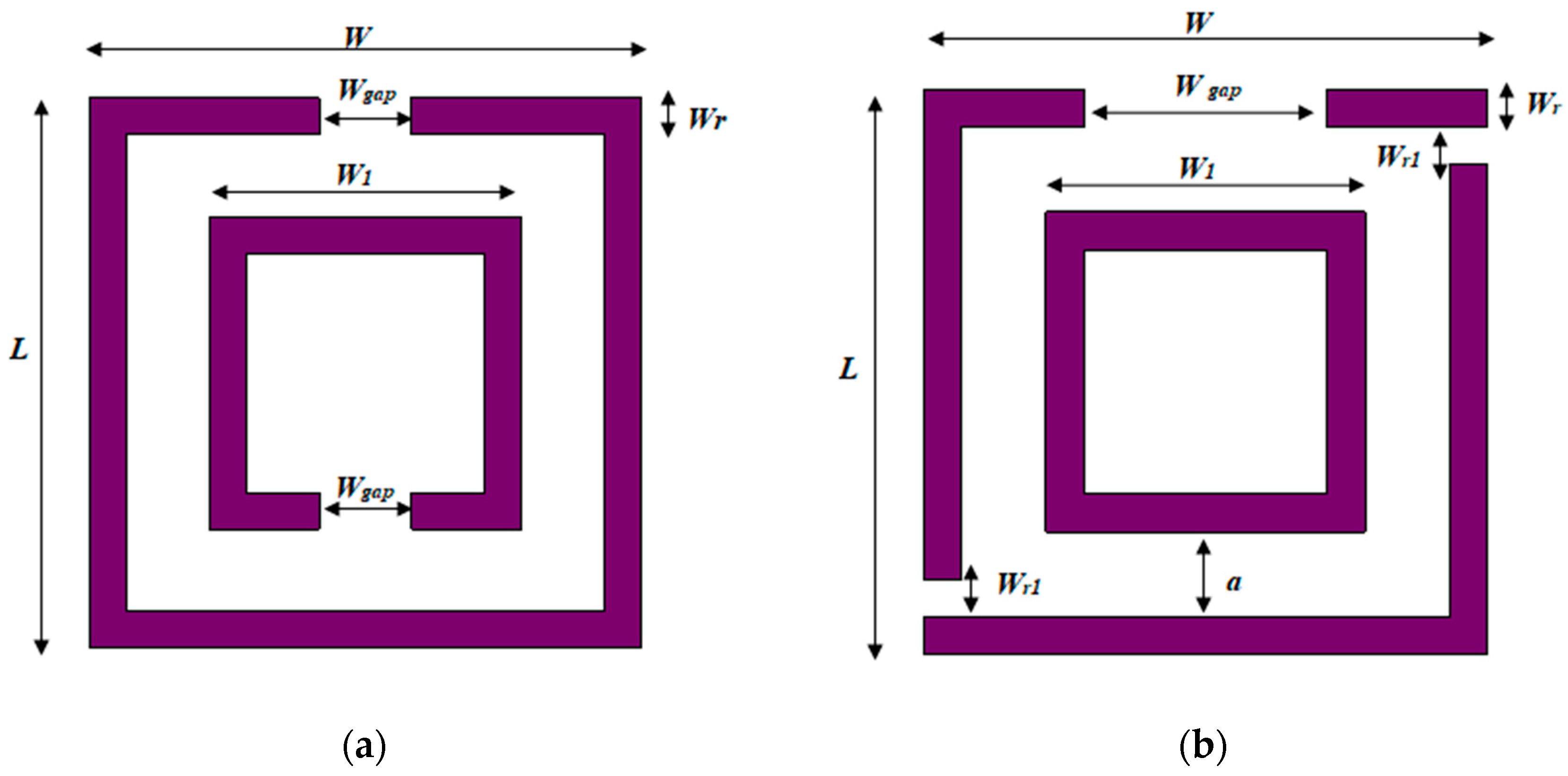
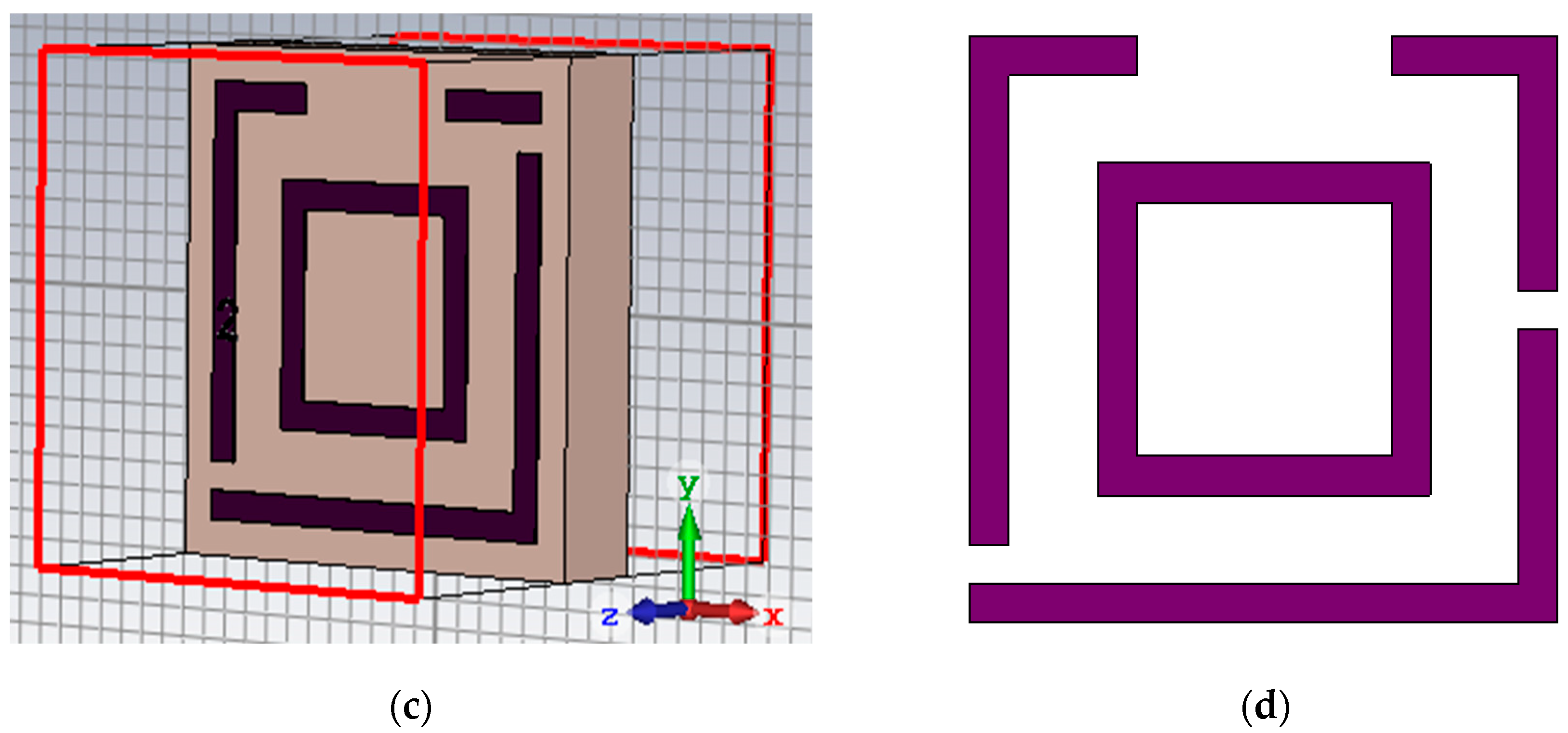
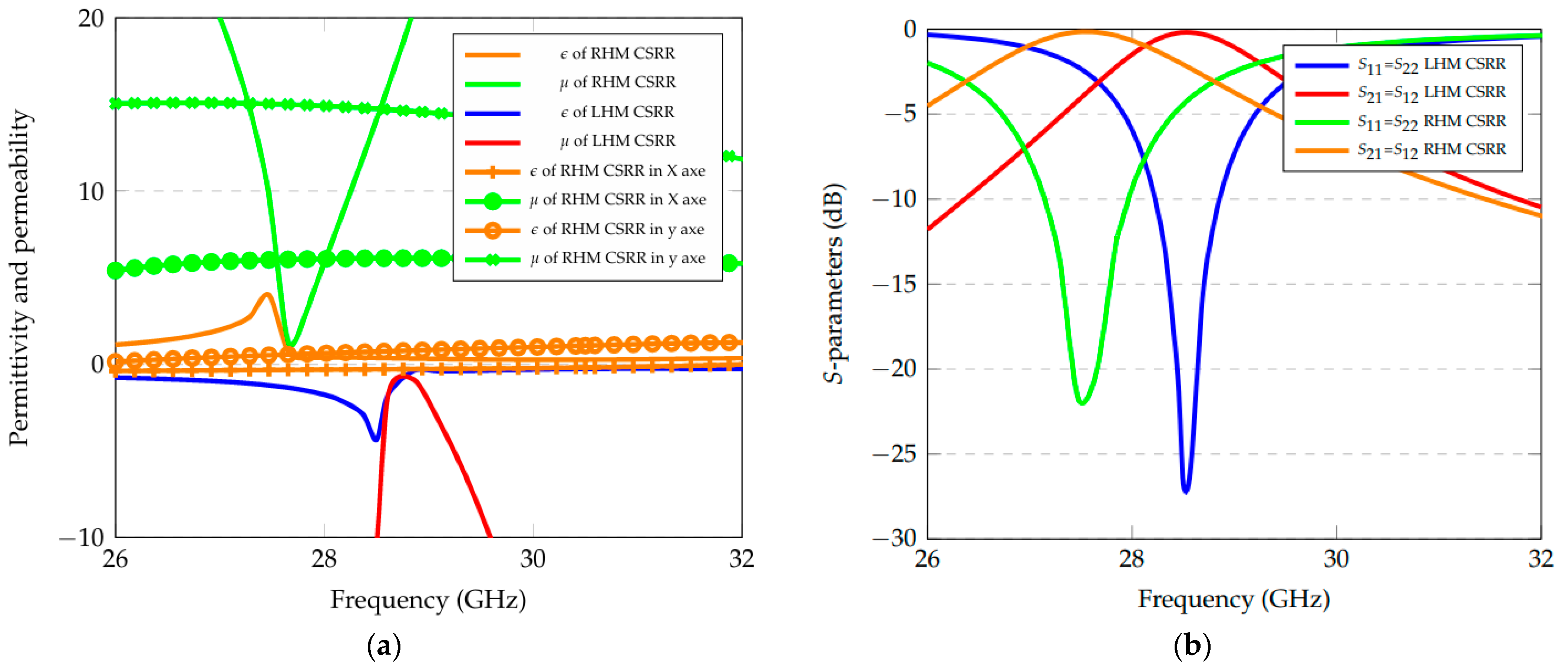
2.1. Complementary Split-Ring Resonator Unit Cell Design
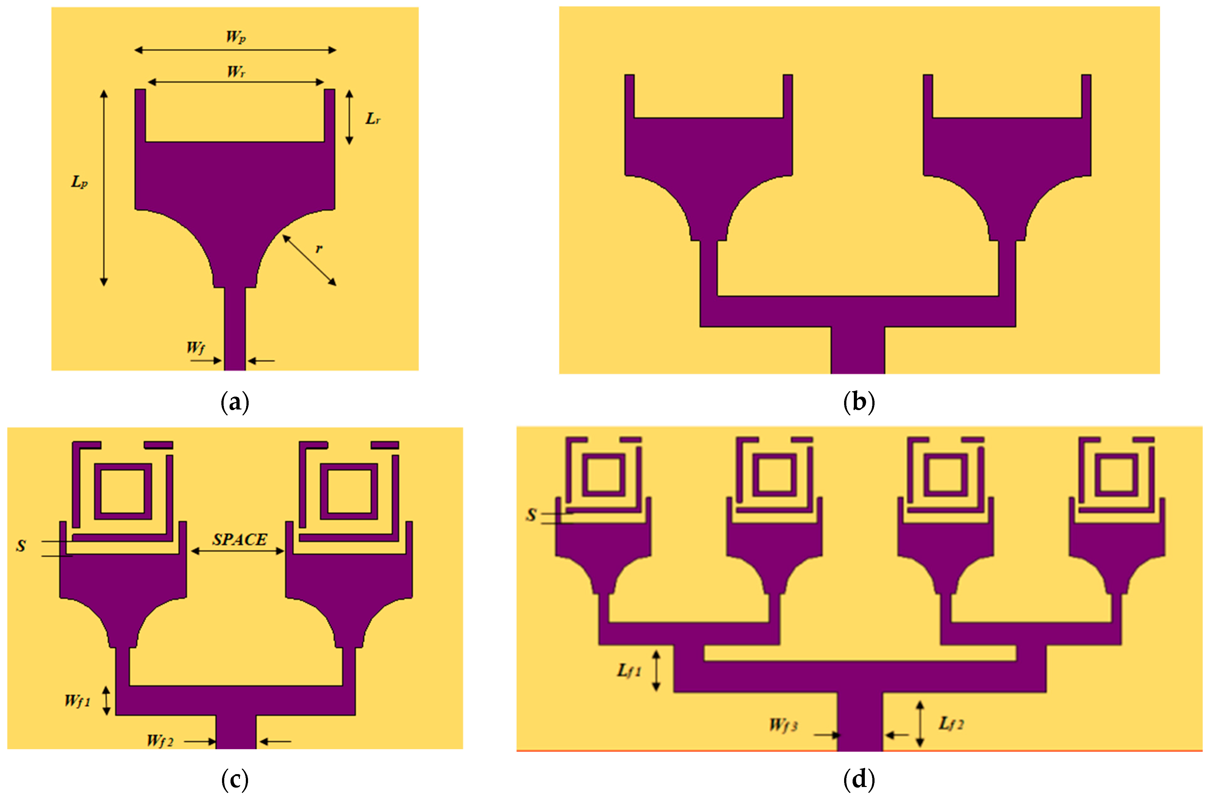
The proposed design was inspired by the conventional structure (Figure 1a) discussed in [6,7,8,9,10,11,12]. Figure 1b and Figure 1c show, respectively, the CSRR structure and the simulation setup using the RT/Roger Duroid 5880 substrate (manufactured by Rogers Corporation, Chandler, AZ, USA) with a thickness of 0.787 mm. The E and H fields are applied on the x- and y-axis, respectively, while the EM wave excitation is applied through the z-axis. The aim of analyzing the resonator in the perpendicular direction is to ensure strong coupling and resonance interaction between the CSRR and the patch. Therefore, the impact on effective permittivity and permeability leads to improvements in both gain and efficiency.
Note that in Figure 1b, the included metamaterial is a Right-Handed Material (RHM) characterized by three gaps in the first ring, where related dimensions are reported in Table 1, while in Figure 1d, the metamaterial is a Left-Handed Material (LHM). Note that, at a specific frequency, an RHM exhibits positive permittivity and permeability, while an LHM shows negative permittivity and permeability.
Therefore, the first step was to optimize the CSRR structure for metamaterial properties (RHM or LHM) by simply changing the location of the gap on the right of the outer ring (from the top for the RHM configuration to the middle for the LHM), leading to a different distribution of EM fields in the structure.
Figure 2a shows both relative permittivity εr and permeability μr of the two CSRRs (Figure 1b and Figure 1d, respectively), where the first design exhibits a positive permittivity and permeability contrary to the second one that presents a negative index. Furthermore, the two parameters εr and μr of the resonator structure presented in Figure 1b were also evaluated in x- and y-axis excitation, exhibiting a negative permittivity in the x-axis (Figure 2a). Table 2 reports the optimized values for each CSRR parameter.
Figure 2b illustrates the S-parameters for both the RHM- and LHM-CSRR structures, showing that the RHM one resonates at 27.46 GHz, while the LHM structure resonates at 28.76 GHz. With close results, we kept both options for the next step before performing a final optimization round with the retained structure.
Both relative permeability and permittivity were extracted through the Nicolson–Ross–Weir (NRW) method [45], depending on S11 and S21 parameters by considering lossless and homogeneous materials [46] as follows:
μ r = 2 j Kd 1 X 2 1 + X 2
ε = 2 j Kd 1 X 1 1 + X 1
where d and K represent the substrate thickness and the free-space wave number, respectively. As for X1 and X2, they are evaluated as follows [46]:
X1 = S21 − S11
X2 = S21 + S11.

2.2. Array Design

The design of the proposed array started with the design of a square single-patch antenna of initial dimensions Wp = Lp = 4.34 mm, calculated from [7]:
W p = c 2 f o ε r + 1 2
The width and the length of the ground plane, Wg = Lg = 9.062 mm, have been calculated as:
Wg = Wp + 6 h
Lg = Lp + 6 h
The initial square patch antenna did not resonate in the 27–31 GHz band. It was thus optimized (Wp = Lp = 3.8 mm) and slotted by two arcs (Figure 3a) of radius r = 1.5 mm, built on the RT Roger 5880 substrate and fed by a 50 Ω microstrip line (of width Wf = 0.40 mm). Note that the patch was slotted at its top by a rectangle of dimensions Wr =3.40 mm and Lr = 1 mm. Next, the patch was duplicated at a distance of 0.28λ0, leading to a two-element array (Figure 3b). Here, λ0 states for the free space wavelength at 28 GHz. Then, a CSRR was added to each element (Figure 3c), with Wf1 = 1 mm and Wf2 = 1.2 mm (note that only the RHM configuration is displayed for conciseness, while both RHM and LHM were simulated). Finally, the structure was further duplicated to get a four-CSRR array with Lf1 = 1.85 mm, Wf3 = 1.80 mm, and Lf2 = 2.40 mm (Figure 3d), leading to a miniaturized size of 27.93 × 13 mm2.
Depending on the targeted application and the retained configuration [1,2,3,4,5,6,7,8,9,10,11,12,13,14,15,16,17,18,19,20], the steps in designing CSRRs can vary in terms of size, shape, and combination with the patch antenna. For instance, in [16,17,18,19,20], ground-loaded CSRRs with metasurface configurations utilized compact CSRR structures (less than 0.1λ0 × 0.1λ0), leading to a small CSRR array with enhanced gain, efficiency, and bandwidth. Compared to previous approaches, the proposed CSRR design features a moderate size (0.28λ0 × 0.28λ0) and a different metal structure to further improve its gain, efficiency, and bandwidth. Those characteristics made it easy to be integrated and implemented with different antenna designs. Moreover, simply adjusting the gap position enables the structure to achieve negative permittivity and permeability in different frequency bands, which is suitable for negative-index metamaterial applications.
Additionally, unlike previous studies, the proposed approach integrates a single CSRR and patch antenna within the same layer, thus reducing fabrication complexity and enhancing the radiation characteristics.

2.3. Final Optimization Round

An optimization round was then run to further enhance the radiation parameters of the designed array. It started by optimizing the performance of the single antenna, focusing on the parameters r, Wr, and Lr. The radius r was optimized for an impedance matching of 50 Ω, while Wr and Lr dealt with the antenna’s radiation characteristics optimization. After increasing the gain of the single antenna from 5 dBi to 6 dBi, adding the second element allowed for an increase in the gain to 8 dBi (Figure 3c). Similarly, with the four-element array, the gain and efficiency were further improved. The initial and optimized values are reported in Table 3, while the antenna performance simulations are discussed in the next section.
In this work, a single CSRR resonator has been integrated into the single-patch layer. As they are placed in the same layer, since the patch generates EM waves propagating from the bottom to the top, the CSRR interacts with such EM waves in the perpendicular direction. Also, the choice of a moderate size (0.28 λ0 × 0.28 λ0) simplifies the manufacturing process while enhancing performance without significantly increasing the entire antenna size. In addition, the shape of the resonator structure, as well as the gap spacing, is carefully optimized to meet certain fabrication constraints while leading to better impedance matching and enhanced radiation performance.
Depending on the CSRR performance and its placement (next to the patch or to the ground plane), integrating a resonator in a patch antenna will modify the current distribution and reduce the spurious wave propagation losses [47]. This will lead to performance improvement at the resonance frequency.

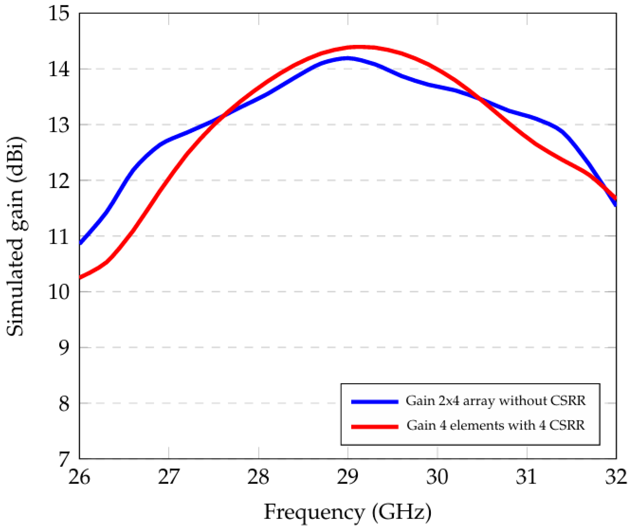
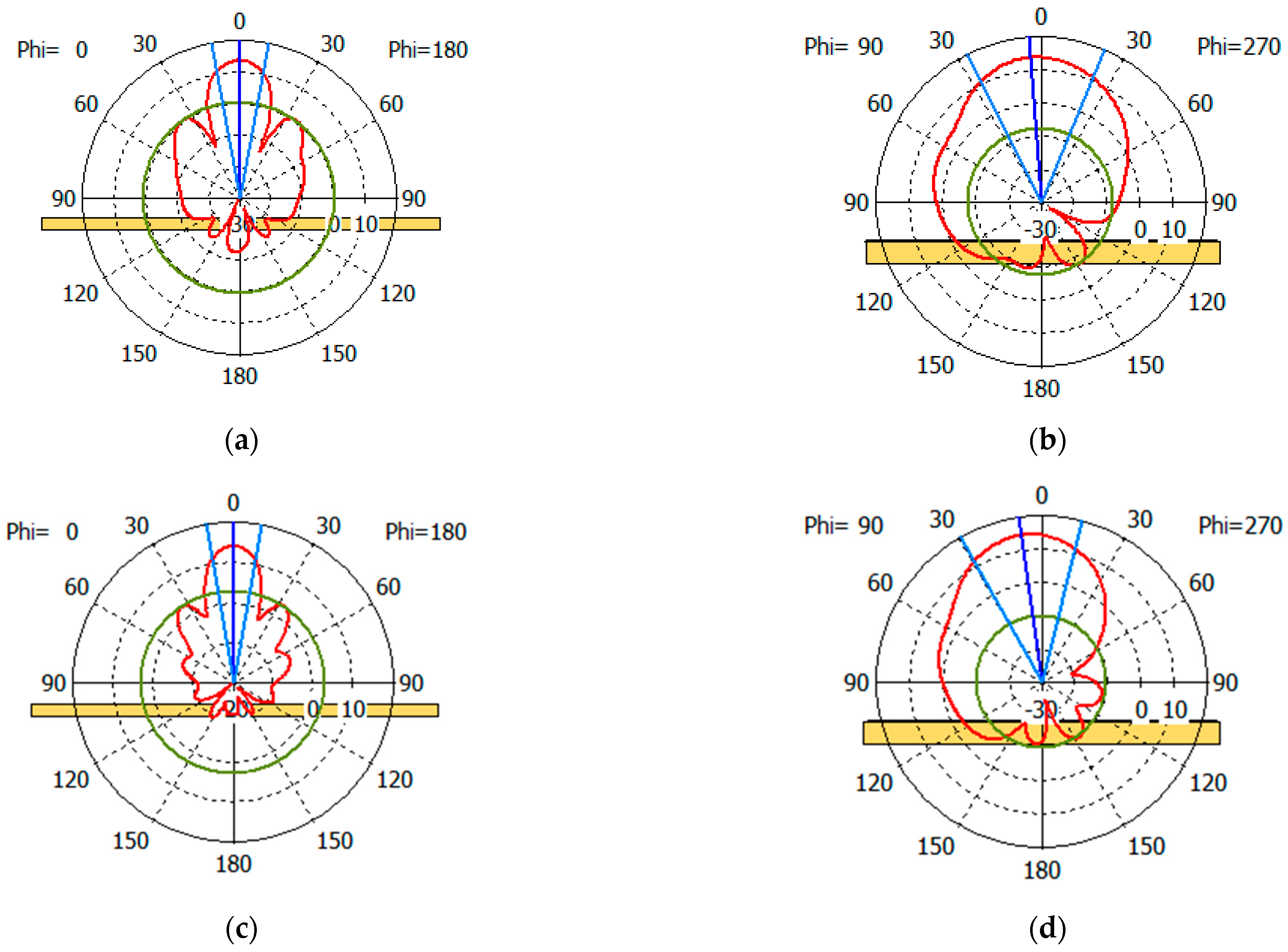
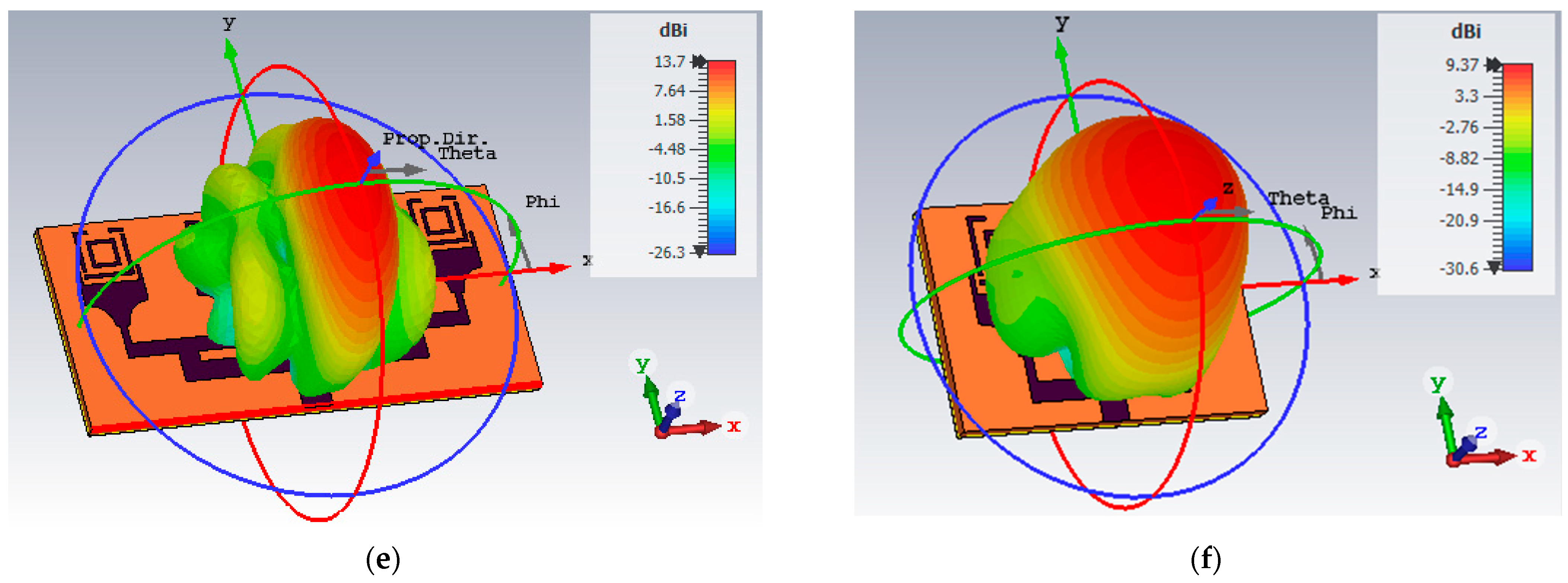
3. Simulation Results

The CST studio suite software 2022 has been used to simulate the antenna in the range 24–32 GHz. As illustrated in Figure 4, the E-field of a 2 × 1 antenna array (Figure 3b) is highly concentrated (with a maximum of 695 V/m) at the top surface of the patch, indicating that placing a SRR as resonator at this location can ensure a strong EM coupling with the E-field generated by the patch. Also, instead of placing a resonator structure on the lateral sides, positioning it at the top further enhances the impedance matching and radiation characteristics while maintaining the compactness of the antenna.
Figure 5a illustrates the S11 parameter for the four design steps (Figure 3). Note that the four-element array with RHM-CSRRs exhibits an S11 value of −45 dB at 28 GHz. Moreover, the four-element array with LHM-CSRR configuration resonates at the same frequency, but with a relatively lower S11. Consequently, the proposed configuration contains 4-RHM-CSRR, while the entire antenna can operate from 27.39 GHz to 29 GHz.
Next, the S11 parameter was simulated for different values of the gap s (from 0.2 mm to 1 mm) between the patch and the RHM-CSRR (Figure 3d). As shown in Figure 5b, the value of s = 0.4 mm exhibits a better reflection coefficient of −45 dB compared to the other values.
Also, the space between the radiator elements plays a crucial role in the antenna performance. Figure 6 shows that for three different values of space parameter (i.e., 0.5 λ0, 0.39λ0, and 0.28λ0), the last value (0.28λ0) allows for the obtainment of better gain and return loss.
The simulated gain of the array is shown in Figure 7. As expected, the gain of the array with CSRRs is significantly higher than the one without CSRRs (maximum gain of 14.5 dBi at 29 GHz and 13.7 dBi at 28 GHz vs. 12.5 dBi at 29 GHz and 12 dBi at 28 GHz).
Moreover, Figure 8 shows a comparison between the simulated array efficiency with or without CSRRs, reaching a relatively stable value of around 97% with the CSRRs, while the antenna without CSRRs exhibits a lower and unstable efficiency value. Furthermore, the antenna input impedance shown in Figure 9 exhibits a real part close to 50 Ω, as well as an imaginary part of 0 Ω at the targeted frequency of 28 GHz.

Miniaturized Array Antenna

In this section, the impact of adding the CSRRs is discussed in terms of miniaturization. As we can notice from Figure 10, further increasing the number of elements from four to eight (2 × 4 array without CSRR) not only did not reach the performance of the proposed four-element array with CSRR but also required a larger space. Those findings demonstrate that the use of the resonator is an efficient approach for antenna miniaturization without decreasing gain. The proposed antenna demonstrated a reduced size of about 20% compared to the 2 × 4 elements without CSRR.
Then, by comparing the obtained size with those of recent works, we can notice that the proposed array is of smaller size than the ones described in [3,11,18], while the respective sizes are 20 × 20 mm2, 36 × 35 mm2, and 13 × 52.87 mm2.
Further, the 3D radiation patterns shown in Figure 11 in both E-plane (Figure 11a,c) and H-plane (Figure 11b,d) demonstrate low side lobe levels at −13 dB and −22 dB, respectively. Also, the array achieves good radiation characteristics at both 28 GHz and 29 GHz with, respectively, a narrow beam of 20° and 49° on the E-plane and 19° and 43° on the H-plane.

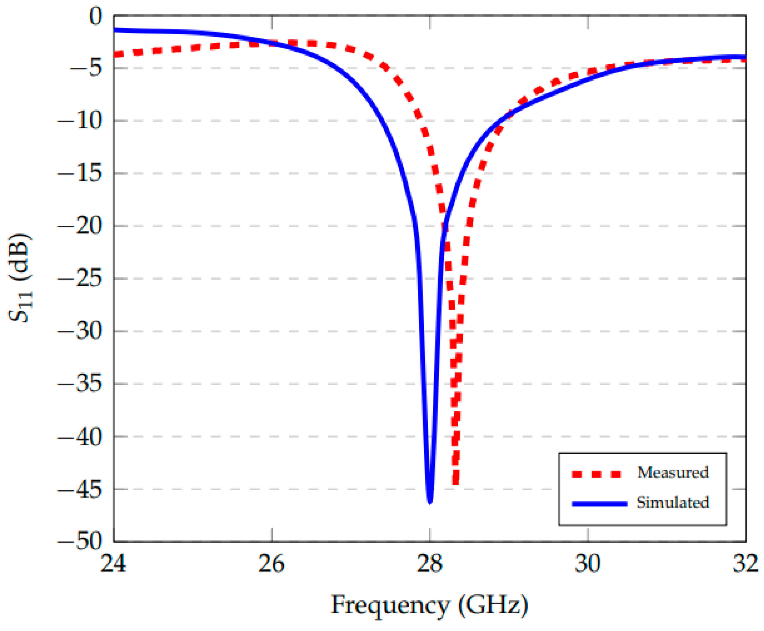
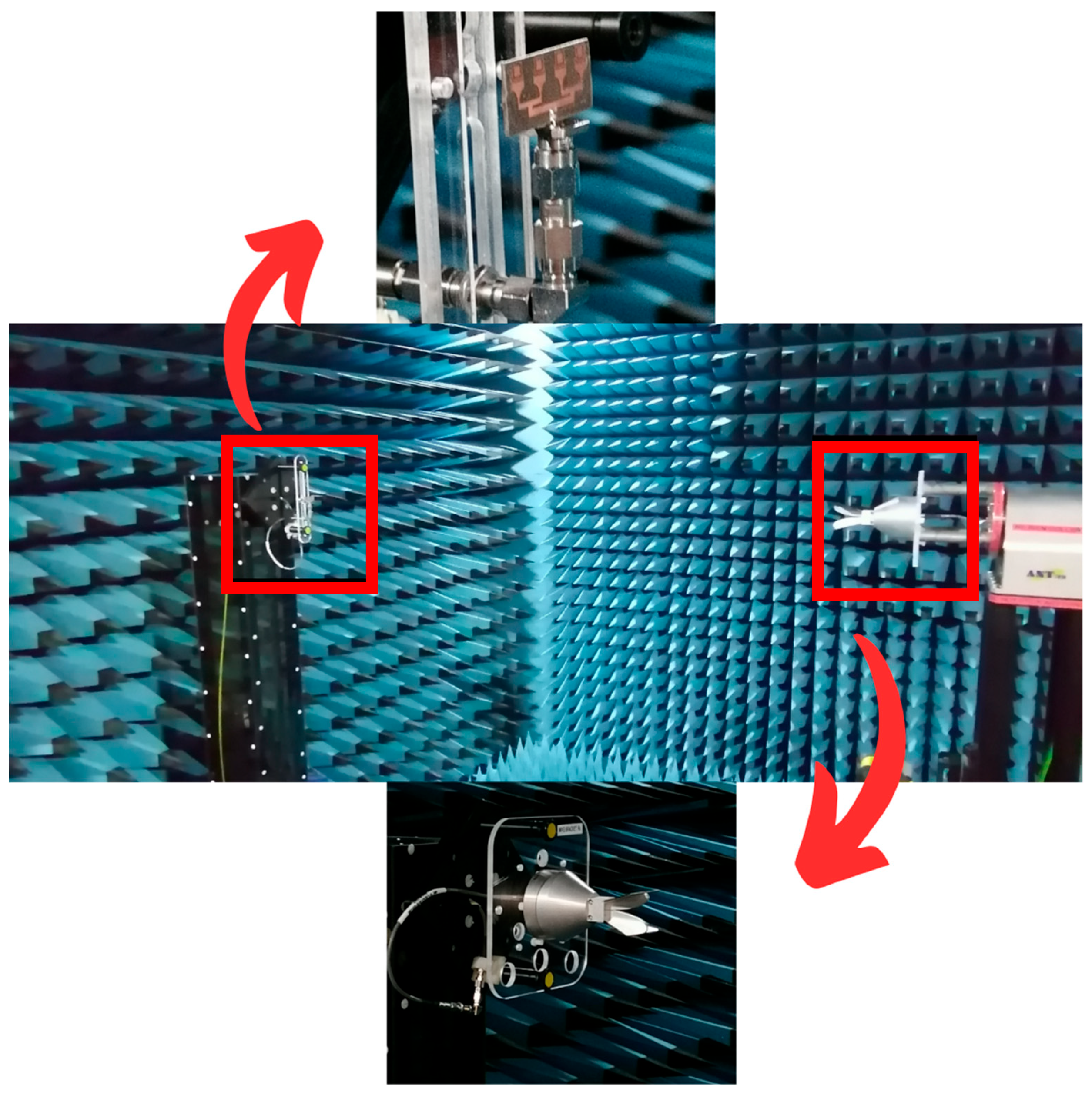
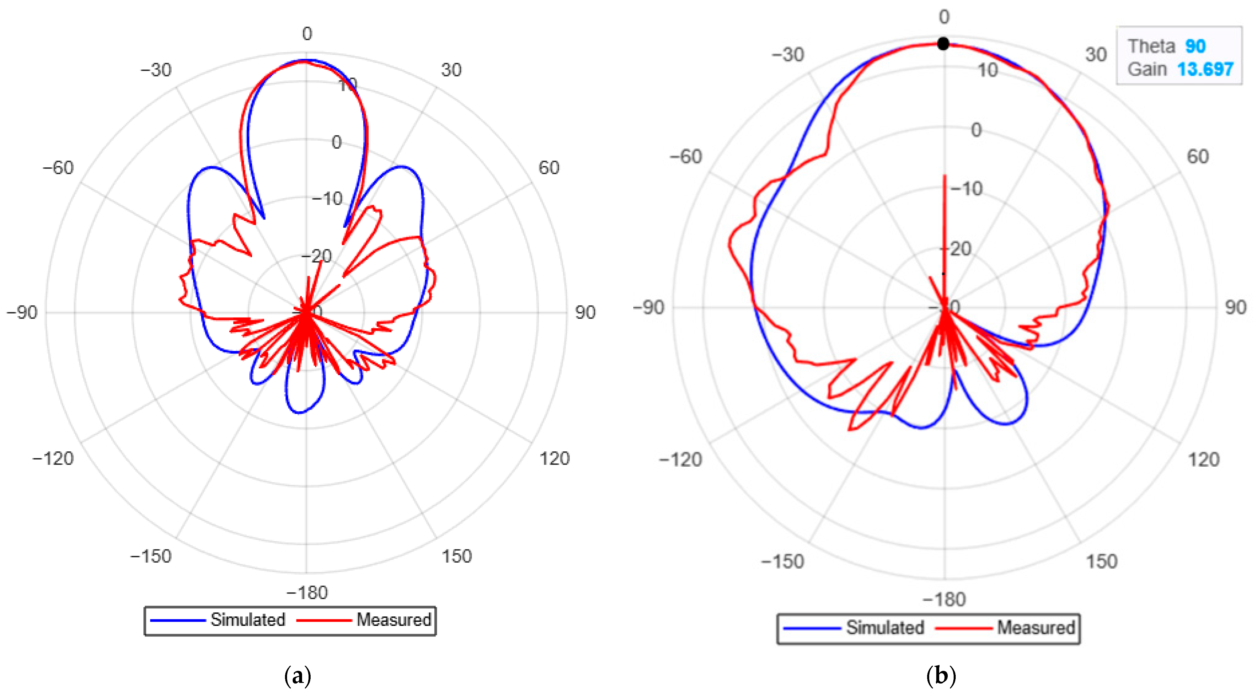
4. Experimental Results

The proposed 5G mm-wave antenna was fabricated in PCB layout technology. Figure 12a and Figure 12b show, respectively, the measurement bench with the Anritsu MS46522B VNA (Vector Network Analyzer) and the fabricated antenna. A measured S11 parameter value of −44 dB was obtained (Figure 13), while the resonance frequency was shifted from 28 GHz to 28.32 GHz due to the discrepancies in impedance matching in the fabricated antenna. By comparing the fabricated PCB and the original CST design, minor inconsistencies in the arc slots (identified by r in Figure 3) across all four radiator elements could explain the resonance frequency shift.
The radiation patterns and the gain were measured in an anechoic chamber, with a distance of 1 m between the measured antenna and a reference horn antenna (Figure 14). It shows a respective gain and directivity of 13.69 dBi and 14.2 dBi, as well as an efficiency of 96%. Figure 15a,b shows the comparison between measured and simulated radiation patterns in the E and H-plane at the target frequency, knowing that the fabricated antenna resonates at 28.32 GHz. Both results demonstrated a maximum gain of 13.69 dBi (Figure 15b). The measurements also show a beamwidth of 22° and 37.8° in the respective E-plane and H-plane at the targeted frequency (Figure 15), while the simulation results predicted a beamwidth of 20° and 49°.
Despite the slight difference, the measured data offer good agreement with simulated results at the targeted frequency.
Hence, Table 4 highlights the compact size of the proposed array compared to the antenna arrays described in [3,10,11,15,18]. Note also that the works reported in [13,14,15,16] have adopted a metasurface metamaterial approach to improve the antenna gain. Despite that, the fabrication was not straightforward. A higher gain and efficiency were obtained compared to the loaded CSRR arrays mentioned in [6,7,8,9,10,11]. Further, the antenna has a wide bandwidth compared to some of the listed works. Simultaneously, it exhibits a narrow beamwidth.
Note that, from a volume size point of view, the proposed antenna is more compact (27.4 × 13 × 0.787 mm3) compared to the one discussed in [13], where the size is 20 × 20 × 7 mm3. Moreover, the obtained S11 and efficiency values can be advantageously compared to the above-mentioned references.
Moreover, and according to the technical specifications listed in Table 1, the proposed antenna structure can be applied in various 5G applications, including 5G networks, industrial IoT, augmented reality (AR)/virtual reality (VR), healthcare, and smart cities as well.

5. Conclusions

This paper deals with the design of a new four-element patch array for 5G mm-wave communication systems. By incorporating four CSRR resonators, it achieves a respective high gain and high efficiency of about 14 dBi and 97%, along with a bandwidth of 1.5 GHz. The radiation characteristics were also enhanced by adding the CSRR structures on the patch layer, leading to compact size, low side lobes, and narrow beamwidth. While simulation results indicate a resonance frequency at 28 GHz, the difference with regard to the measured one did not exceed 1%, mainly due to fabrication tolerances. However, despite the obtained high gain (around 14 dBi), the very high-gain requirements of certain 5G applications, such as Fixed Wireless Access (FWA), Radar Systems, and Wireless Backhaul, cannot be met. On the other hand, the proposed antenna’s performance fulfills the requirements of applications, including 5G networks, IoT industrial, augmented reality (AR)/virtual reality (VR), and healthcare. The next step will be to improve the proposed antenna directivity in the context of beamforming applications.

Author Contributions

Conceptualization: M.L.T., T.P.V. and M.C.E.Y.; Data curation: A.Z. and N.C.; Formal analysis: A.Z. and M.L.T.; Funding acquisition: M.L.T. and T.P.V.; Investigation: A.Z., N.C., T.P.V. and M.L.T.; Methodology: A.Z. and M.L.T.; Project administration: M.L.T. and T.P.V.; Resources: M.L.T. and T.P.V.; Software: A.Z.; Supervision: M.L.T. and T.P.V.; Validation: A.Z., M.L.T., N.C. and T.P.V.; Visualization: A.Z., M.L.T., T.P.V. and M.C.E.Y.; Writing—original draft: A.Z. and M.L.T.; Writing—review & Editing: A.Z., M.L.T., T.P.V. and M.C.E.Y. All authors have read and agreed to the published version of the manuscript.

Funding

This research received no external funding.

Data Availability Statement

All used data are available in the article.

Conflicts of Interest

The authors declare no conflict of interest.

References

  1. Sadeghi-Marasht, S.; Sharawi, M.S.; Zhu, A. Dual-Band Circularly Polarized Antenna Array for 5 G Millimeter-Wave Applications. IEEE Open J. Antennas Propag. 2022, 3, 314–323. [Google Scholar] [CrossRef]
  2. Saleh, C.M.; Almajali, E.; Jarndal, A.; Yousaf, J.; Alja’Afreh, S.S.; Amaya, R.E. Wideband 5G Antenna Gain Enhancement Using a Compact Single-Layer Millimeter Wave Metamaterial Lens. IEEE Access 2023, 11, 14928–14942. [Google Scholar] [CrossRef]
  3. Efri, S.; Rusmono, R.; Diamah, A.; Vinda, K. Ultra-wideband Microstrip Array Antenna for 5G Millimeter-wave Applications. J. Commun. 2020, 15, 198–204. [Google Scholar]
  4. Shen, X.; Liu, Y.; Zhao, L.; Huang, G.-L.; Shi, X.; Huang, Q. A Miniaturized Microstrip Antenna Array at 5G Millimeter-Wave Band. IEEE Antennas Wirel. Propag. Lett. 2019, 18, 1671–1675. [Google Scholar] [CrossRef]
  5. Bangash, K.; Ali, M.M.; Maab, H.; Ahmed, H. Design of a Millimeter Wave Microstrip Patch Antenna and Its Array for 5G Applications. In Proceedings of the 2019 International Conference on Electrical, Communication, and Computer Engineering (ICECCE), Swat, Pakistan, 13–14 July 2019. [Google Scholar]
  6. Frist, Y.; Elhabchi, M.; Srifi, M.N. A Novel Millimeter-Wave Miniaturized UWB Antenna Developed for 5G Applications Using Four L-Shaped and SRR Slots. In Proceedings of the 2023 6th International Conference on Advanced Communication Technologies and Networking (CommNet), Rabat, Morocco, 11–13 November 2023. [Google Scholar]
  7. Vinoth, M.; Vallikannu, R. Design and Analysis of Metamaterial Patch Antenna 5G and X Band Applications. In Proceedings of the 2021 International Conference on Computer Communication and Informatics (ICCCI), Coimbatore, India, 19–22 July 2021. [Google Scholar]
  8. Kumar, R.; De, A. Design of High Gain, Twin-band Antenna with CSRR for 5G Applications. In Proceedings of the 2022 IEEE Silchar Subsection Conference (SILCON), Silchar, India, 4–6 November 2022. [Google Scholar]
  9. Estu, T.T.; Murad, N.A.; Sugandi, G.; Praludi, T.; Yusoff, M.F.M.; Wijayanto, Y.N. Directive Beam Metamaterial Inspired Transparent Folded Dipole Antenna for Millimeter Wave Applications. In Proceedings of the 2023 International Conference on Radar, Antenna, Microwave, Electronics, and Telecommunications (ICRAMET), Bandung, Indonesia, 15–16 November 2023. [Google Scholar]
  10. Selvaraju, R.; Jamaluddin, M.H.; Kamarudin, M.R.; Nasir, J.; Dahri, M.H. Mutual Coupling Reduction and Pattern Error Correction in a 5G Beamforming Linear Array Using CSRR. IEEE Access 2018, 6, 65922–65934. [Google Scholar] [CrossRef]
  11. Nadzir, N.M.; Rahim, M.K.A.; Murad, N.A.; Himdi, M. Millimeter Wave Microstrip Antenna with CSRR for 5G Application. In Proceedings of the 2020 International Symposium on Antennas and Propagation (ISAP), Osaka, Japan, 25–28 January 2021. [Google Scholar]
  12. Sharma, G.; Kumar, M. SRR integrated CDRA Hybrid Antenna for 5G mm-Wave Communication. In Proceedings of the 2023 First International Conference on Microwave, Antenna and Communication (MAC), Prayagraj, India, 24–26 March 2023. [Google Scholar]
  13. Adiga, A.K.; Manjunath, A.K.; Giddegowda, Y.; Bhatkoorse, R. Gain Enhancement of 4 × 4 mm-Wave Patch Array with Dielectric Shells and Metamaterial Lens: A Comparative Study. IEEE Wirel. Antenna Microw. Symp. 2022, 1, 1–5. [Google Scholar]
  14. Nandigama, S.V.; Bharath, K.; Krishna, D.R. Gain Enhancement of an Aperture Coupled Antenna using Metasurface at mm-wave Frequency. In Proceedings of the 2021 IEEE Indian Conference on Antennas and Propagation (InCAP), Jaipur, Rajasthan, India, 13–16 December 2021. [Google Scholar]
  15. Khalily, M.; Tafazolli, R.; Xiao, P.; Kishk, A.A. Broadband mm-Wave Microstrip Array Antenna with Improved Radiation Characteristics for Different 5G Applications. IEEE Trans. Antennas Propag. 2018, 66, 4641–4647. [Google Scholar] [CrossRef]
  16. Mishra, P.; Komatineni, R.; Kulat, K.D. Millimeter Wave MPA using Metamaterial-Substrate Antenna Array for Gain Enhancement. In Proceedings of the 2023 National Conference on Communications (NCC), Guwahati, India, 23–26 February 2023. [Google Scholar]
  17. Chowdhury, A.; Ranjan, P. SRR and DGS-Based Highly Isolated Four-Port MIMO Antenna for Mid-5G Band and High-5G Band. MAPAN J. 2024, 39, 321–336. [Google Scholar] [CrossRef]
  18. Essid, C.; Samet, A. A Design of Phased Array Antenna with Metamaterial Circular SRR for 5G Applications. In Proceedings of the 28th IEEE Annual International Symposium on Personal, Indoor, and Mobile Radio Communications (PIMRC), Montreal, QC, Canada, 8–13 October 2017. [Google Scholar]
  19. Cai, X.; He, Y.; Xu, J.; Qin, K.; Luo, Y. A Dual-Band Millimeter-Wave Antenna Loaded with CSRR. In Proceedings of the International Applied Computational Electromagnetics Society Symposium (ACES), Beijing, China, 8–11 April 2019. [Google Scholar]
  20. Ameen, A.M.; Yousef, B.M.; Attiya, A.M. Mutual Coupling Reduction Between MM-Wave Microstrip Antennas Using CSRR Metamaterial Structure. In Proceedings of the 37th National Radio Science Conference (NRSC), Cairo, Egypt, 25–27 August 2020. [Google Scholar]
  21. Rappaport, T.S.; Sun, S.; Mayzus, R.; Zhao, H.; Azar, Y.; Wang, K.; Wong, G.N.; Schulz, J.K.; Samimi, M.; Gutierrez, F. Millimeter Wave Mobile Communications for 5G Cellular: It Will Work! IEEE Access 2013, 1, 335–349. [Google Scholar] [CrossRef]
  22. Bai, T.; Heath, R.W. Coverage and Rate Analysis for Millimeter-Wave Cellular Networks. IEEE Trans. Wirel. Commun. 2015, 14, 1100–1114. [Google Scholar] [CrossRef]
  23. Niu, Y.; Li, Y.; Jin, D.; Su, L.; Vasilakos, A.V. A Survey of Millimeter Wave Communications (mmWave) for 5G: Opportunities and Challenges. Wirel. Netw. 2015, 21, 2657–2676. [Google Scholar] [CrossRef]
  24. MacCartney, G.R.; Rappaport, T.S.; Samimi, M.K.; Sun, S. Millimeter-Wave Wireless Communications: New Results for Rural Connectivity. IEEE J. Sel. Areas Commun. 2017, 35, 1663–1677. [Google Scholar] [CrossRef]
  25. Yeh, C.H.; Chien, H.C.; Wu, Y.F.; Chow, C.W.; Chi, S.; Tsai, H.M. Performance Evaluation of 28-GHz Millimeter-Wave Wireless Access Networks for Satellite Communications. IEEE Trans. Veh. 2018, 67, 1227–1235. [Google Scholar]
  26. Akyildiz, I.F.; Jornet, J.M.; Han, C. Terahertz Band: Next Frontier for Wireless Communications. Phys. Commun. 2014, 12, 16–32. [Google Scholar] [CrossRef]
  27. Skolnik, M.I. Radar Handbook, 3rd ed.; McGraw-Hill: New York, NY, USA, 2008. [Google Scholar]
  28. Patole, S.M.; Torlak, M.; Wang, D.; Ali, M. Automotive Radar: A Review of Signal Processing Techniques. IEEE Signal Process. Mag. 2017, 34, 22–35. [Google Scholar] [CrossRef]
  29. Ghosh, A.; Thomas, T.A.; Cudak, M.C.; Ratasuk, R.; Moorut, P.; Vook, F.W.; Rappaport, T.S.; Sun, S. Millimeter-Wave Enhanced Local Area Systems: A High-Data-Rate Approach for Future Wireless Networks. IEEE J. Onselected Areas Commun. 2014, 32, 1152–1163. [Google Scholar] [CrossRef]
  30. Wild, T.; Tonn, K. 5G with Fixed Wireless Access: Fixed Wireless Access Solutions for 5G. In Ericsson White Paper; Ericsson: Stockholm, Sweden, 2020. [Google Scholar]
  31. Sadeghi, M.; Sadigh, A.K.; Rasti, M.; Pakravan, M.R. Wireless Communications and IoT for Smart Industry. IEEE Internet Things J. 2020, 7, 3991–4002. [Google Scholar]
  32. Palattella, M.R.; Dohler, M.; Grieco, A.; Rizzo, G.; Torsner, J.; Engel, T.; Ladid, L. Internet of Things in the 5G Era: Enablers, Architecture, and Business Models. IEEE J. Onselected Areas Commun 2016, 34, 510–527. [Google Scholar] [CrossRef]
  33. Shajaiah, H.; Abdel-Hadi, A.; Clancy, C. Overview of Spectrum Sharing Techniques for 5G Wireless Networks. IEEE Wirel. Commun. 2017, 24, 72–79. [Google Scholar]
  34. Boccardi, F.; Heath, R.W.; Lozano, A.; Marzetta, T.L.; Popovski, P. Five Disruptive Technology Directions for 5G. IEEE Commun. Mag. 2014, 52, 74–80. [Google Scholar] [CrossRef]
  35. Chakareski, J. VR/AR Immersive Communication: Caching, Edge Computing, and Transmission Trade-Offs. IEEE Commun. Mag. 2018, 56, 98–103. [Google Scholar]
  36. Fettweis, G.; Alamouti, S. 5G: Personal Mobile Internet Beyond What Cellular Did to Telephony. IEEE Commun. Mag. 2014, 52, 140–145. [Google Scholar] [CrossRef]
  37. Khan, W.Z.; Xiang, Y.; Aalsalem, M.Y.; Arshad, Q. IoT-Based Smart Healthcare: Key Applications and Challenges. IEEE Access 2018, 6, 62230–62250. [Google Scholar]
  38. Ghasempour, Y.; da Silva, C.R.C.M.; Knightly, E.W. Millimeter-Wave Communication for Wireless Virtual Reality: A Measurement Study. IEEE Trans. Wirel. Commun. 2021, 20, 5653–5669. [Google Scholar]
  39. Hayat, S.; Yanmaz, E.; Muzaffar, R. Survey on Antenna Technologies for 5G mmWave UAV Networks. IEEE Commun. Surv. Tutor. 2020, 22, 1912–1940. [Google Scholar]
  40. Fotouhi, A.; Qiang, H.; Ding, M.; Hassan, M.; Giordano, L.G.; Garcia-Rodriguez, A.; Yuan, J. Survey on UAV Cellular Communications: Practical Aspects, Standardization Advancements, Regulation, and Security Challenges. IEEE Commun. Surv. Tutor. 2019, 21, 3417–3442. [Google Scholar] [CrossRef]
  41. Andrews, J.G.; Buzzi, S.; Choi, W.; Hanly, S.V.; Lozano, A.; Soong, A.C.K.; Zhang, J.C. What Will 5G Be? IEEE J. Onselected Areas Commun. 2014, 32, 1065–1082. [Google Scholar] [CrossRef]
  42. Parkvall, S.; Dahlman, E.; Furuskar, A.; Frenne, M. NR: The New 5G Radio Access Technology. IEEE Commun. Stand. Mag. 2017, 1, 24–30. [Google Scholar] [CrossRef]
  43. Zanella, A.; Bui, N.; Castellani, A.; Vangelista, L.; Zorzi, M. Internet of Things for Smart Cities. IEEE Internet Things J. 2014, 1, 22–32. [Google Scholar] [CrossRef]
  44. Xu, Y.; Yuen, C.; Lin, X.; Jin, S. Smart Cities: Edge Computing and AI-Driven Data Processing. IEEE Commun. Mag. 2020, 58, 38–43. [Google Scholar]
  45. Wei, W.B. Automatic measurement of complex dielectric constant and permeability at microwave frequencies. In Proceedings of the IEEE; IEEE: New York, NY, USA, 1974; Volume 62, pp. 33–36. [Google Scholar]
  46. Samuel, P.J.C.; Nagarajan, G. Dual-Band Complementary Split-Ring Resonator Engraved Rectangular Monopole for GSM and WLAN/WiMAX /5G Sub-6 GHz Band (New Radio Band). Prog. Electromagn. Res. C 2021, 113, 251–263. [Google Scholar]
  47. Nupur, S.; Kr, G.N.; Kartikeyan, M.V. Metamaterial inspired CSSRR design for WLAN microstrip patch antenna. In Proceedings of the 11th International Conference on Industrial and Information Systems (ICIIS), Roorkee, India, 3–4 December 2016. [Google Scholar]
Figure 1. (a) Conventional CSRR design, (b) Proposed CSRR design with RHM, (c) CSRR simulation setup, (d) CSRR design with LHM.
Electronics 14 01834 g001aElectronics 14 01834 g001b
Figure 2. (a) Permittivity and permeability of the CSRR unit cell, (b) S-parameters of the CSRR unit cell.
Electronics 14 01834 g002
Figure 3. Design steps of the proposed antenna (a) first step, (b) second step, (c) third step, and (d) fourth step of electrical model of the proposed CSRR.
Electronics 14 01834 g003
Figure 4. Electrical field distribution for a 2 × 1 antenna array.
Electronics 14 01834 g004
Figure 5. (a) Evolution of the S11 parameter during the design process, (b) S11 versus frequency for different values of s.
Electronics 14 01834 g005
Figure 6. S11 and gain versus frequency for different space values.
Electronics 14 01834 g006
Figure 7. Comparison of the array gain with or without CSRR.
Electronics 14 01834 g007
Figure 8. Array efficiency with or without CSRR.
Electronics 14 01834 g008
Figure 9. Real and imaginary part of the input impedance.
Electronics 14 01834 g009
Figure 10. Gain comparison of 2 × 4 antenna and four elements with 4 CSRR.
Electronics 14 01834 g010
Figure 11. Simulated radiation patterns: (a) E-Plane, (b) H-Plane, at 28 GHz. (c) E-Plane, (d) H-Plane, at 29 GHz. (e) 3Dradiation pattern of the four-element CSRR array, (f) 3D radiation pattern of the two-element CSRR array at 28GHz.
Electronics 14 01834 g011aElectronics 14 01834 g011b
Figure 12. (a) S11 parameter measurement setup with VNA, (b) fabricated antenna.
Electronics 14 01834 g012
Figure 13. Measured S11 parameter.
Electronics 14 01834 g013
Figure 14. Radiation measurement setup in anechoic chamber.
Electronics 14 01834 g014
Figure 15. Measured radiation pattern: (a) E-Plane, (b) H-Plane, at 28 GHz. (c) 3D radiation patterns measured at 28.325 GHz.
Electronics 14 01834 g015aElectronics 14 01834 g015b
Table 1. Typical specifications for 28 GHz antenna applications.
ApplicationAntenna Gain (dBi)Bandwidth (GHz)S11 (dB)CompactnessReferences
5G Networks15 to 251 to 2<−15Moderate to High[21,22]
Fixed Wireless Access (FWA)20 to 300.5 to 2<−10Moderate[23,24]
Satellite Communication25 to 400.5 to 2<−15Low to Moderate[25,26]
Radar Systems20 to 351 to 5<−10Moderate[27,28]
Wireless Backhaul25 to 350.5 to 2<−15Moderate[29,30]
Industrial IoT10 to 200.5 to 1<−10High[31,32]
Point-to-Point Communication20 to 301 to 2<−10Moderate[33,34]
AR/VR10 to 201 to 2<−10High[35,36]
Healthcare6 to 150.5 to 1<−10Very High[37,38]
UAVs (Drones)15 to 251 to 2<−10Moderate[39,40]
Broadcasting20 to 301 to 2<−10Moderate[41,42]
Smart Cities10 to 200.5 to 1<−10High[43,44]
Table 2. CSRR parameters: optimized values.
ParameterOptimized Value (mm)
W3.0
L3.0
W11.7
W gap1.3
Wr0.2
Wr10.2
a0.45
Copper Thickness0.017
Table 3. Design array: initial and optimized values.
ParameterInitial Value (mm)Optimized Value (mm)
Wp4.343.80
Lp4.343.80
Wg9.062/
Lg9.062/
Wf0.40.4
r0.21.5
Wr33.4
Lr0.61.0
spaceλ0/2 = 5.363.0
r11.5
Wf10.81.0
Wf21.61.2
Lf11.81.85
Wf321.8
Lf222.4
S10.4
substrate thickness0.7870.787
copper thickness0.0170.017
Table 4. Comparison of the performance of the proposed array with existing similar designs.
AntennaSize
(mm2)
Frequency
(GHz)
Gain
(dBi)
Simulated/
Measured
Beamwidth (°)
E-Plane/
H-Plane
Bandwidth
(GHz)
Simulated/
Measured
S11
(dB)
Simulated/
Measured
Efficiency
(%)
Simulated/
Measured
[1]16.05 × 202812/12.6325.6−20/90
[2]12.8 ×12.826.513/12.7/6−22/−2292
[3]20 × 20288.71/4.47−20/−20/
[4]/287/6−40/
[5]10 × 1024.8513/1.3−19.5/
[6]12 × 10285.79/26–75−40/
[7]4.6 × 4.619.043/0.2−2388
[8]3.2 × 4.2327.37.25/1−3096.5
[9]/287.2/6−25/
[10]32 × 8.625//1−40/
[11]36 × 352813.3/2.2−25/
[12]5 × 5284.07/0.9−2597
[13]20 × 202417.3//−35.18/
[14]28 × 28277.8/1−39/
[15]17.45 × 99.22818.749.56−1586
[16]18 × 2228.514/10.4−40/
[17]60 × 60284.50/3.0−30/
[18]13 × 52.87282.83/8.0−30/
[19]9.2 × 6.8285.80/3.8−20/
[20]8.7 × 172510.00/1.6−31/
Our results27.40 × 132813.7/13.720/491.5/1−45/−4497/96
Disclaimer/Publisher’s Note: The statements, opinions and data contained in all publications are solely those of the individual author(s) and contributor(s) and not of MDPI and/or the editor(s). MDPI and/or the editor(s) disclaim responsibility for any injury to people or property resulting from any ideas, methods, instructions or products referred to in the content.

