Abstract
The accuracy of ultrasonic rangefinders is crucial for mobile robotic navigation systems, yet environmental factors such as temperature, humidity, atmospheric pressure, and wind conditions can influence ultrasonic speed in the air. The primary objective is to investigate how environmental factors influence the output signal of an ultrasonic emitter and to develop a method for improving the accuracy of distance measurements in both outdoor and indoor settings. The research employs a combination of theoretical modeling, statistical analysis, and experimental validation. The research employs an ultrasonic rangefinder integrated with environmental sensors (BME280, Bosch Sensortec GmbH, Kusterdingen, Germany) and wind sensors (WMT700, WINDCAP®, Vaisala Oyj, Vantaa, Finland) to account for environmental influences. Experimental studies were conducted using a prototype ultrasonic rangefinder, and statistical analysis (Student’s t-test) was performed on collected data. The results of estimation by Student’s t-test for 256 measurements demonstrate the maximum effect of air temperature and the minimum effect of relative air humidity on a piezoelectric emitter output signal both outdoors and indoors. In addition, wind parameters affect the rangefinder’s operation. The maximum range of obstacle detection depends on the reflection coefficient of the material that covers the obstacle. The results align with theoretical expectations for highly reflective surfaces. A cascade-forward artificial neural network model was developed to refine distance estimations. This study demonstrates the importance of considering environmental factors in ultrasonic rangefinder systems for mobile robots. By integrating environmental sensors and using statistical analysis, the accuracy of distance measurements can be significantly improved. The results contribute to the development of more reliable navigation systems for mobile robots operating in diverse environments.
1. Introduction
Navigation in mobile robotics has characteristics that prevent the effective use of navigation facilities for other objects. Consequently, to design navigation systems for mobile robots (MRs), several different navigation means and parallel information processing must be used. In addition, the dynamics and kinematics of the object must be taken into account, especially when navigating indoors [1].
Autonomous MR navigation comes in two types: local and global. Creating a movement plan on a digital map is the primary function of global navigation systems. Maneuvers along a predetermined route are planned and managed by local navigation systems. A component of autonomous MR navigation is local navigation, which determines an object’s relative coordinates and movement parameters in a brief period of time—up to ten minutes. Determining the relative Cartesian coordinates and parameters of the MR motion, planning and controlling the MR maneuvers while traveling along a predetermined path, and modifying the global navigation system when determining the object’s absolute coordinates are the primary tasks of local navigation [2].
The most typical examples of using the local navigation system are control of movement on a safe trajectory in limited space and MR navigation in the absence of data from external navigation sources; for example, a positioning system based on the Global Navigation Satellite System (GNSS) fails.
Developing a local navigation system requires specifying the orientation angles (course, pitch, tilt) of the MR and its motion parameters (speed and acceleration) in order to form a given trajectory and release the navigation information continuously. Moreover, the MR coordinates must be determined accurately at short time intervals of (1–10) s. The system has to be autonomous, resistant to noise, interference, and vibrations, with a low power consumption, and of small size [2,3].
Upon analyzing some publications, we can conclude that the local navigation system MR may be implemented using both active (technical vision systems and inertial navigation) and passive (markers, beacons, and satellite) navigation facilities [4,5,6].
Ultrasonic rangefinders are widely used in defectoscopy, autonomous aerial navigation, collision warning systems, and sensor-based localization [7]. This paper focuses on active technical vision systems based on an ultrasonic rangefinder.
Ultrasound scanning based on an n-channel ultrasonic rangefinder has the following practical applications:
- -
- for defectoscopy with nondestructive quality control of materials and products in manufacturing [8];
- -
- in autopilot systems of helicopter microaircraft (RMAVs) with vertical takeoff and landing (VTOL) for autonomous control, navigation, and collision prevention when used in a swarm [9], as well as localization of objects in a ±45° field of view [10] and at distances up to 10 m [11];
- -
- in systems involving the high-speed processing of signals for surrounding territory recognition [12] for fast replanning of a route in real-time when detecting an obstacle [13];
- -
- in sensor devices for simultaneous monitoring of traffic jams and for controlling water levels to prevent sudden floods, which combine an ultrasonic rangefinder with several remote temperature sensors (these devices allow the detection of vehicles with a 99% accuracy, estimation of their speed with average uncertainty up to 5 km/h, classification depending on length with an average uncertainty of up to 0.7 m, and control of a water level in the city with an accuracy of 2 cm) [14,15];
- -
- in a collision warning system installed on the back of a bicycle seat, which evaluates the risk of collision with oncoming cars from behind and generates appropriate warning signals [16];
- -
- in hard-to-reach places, in toxic conditions, in electromagnetically polluted environments, etc., where artificial neural networks are used for tasks of identification and image recognition [17,18,19];
- -
- to solve problems of localization and cartography by incremental mapping [20] and by the information from an ultrasonic sensor ring combined with data from motor encoders [21];
- -
- advanced rangefinders, such as PMNN-PZT monolithic thin-film ultrasonic rangefinders operating at 1 V with a range of 2 m [22,23] and multi-frequency scanning pMUT-based rangefinders, demonstrate superior performance [24,25].
The control system can effectively compensate for environmental errors using an artificial neural network (ANN), but this introduces computational overhead that can affect real-time performance [26,27].
The effective obstacle detection range of modern ultrasonic sensors for long-distance navigation is limited compared with LiDAR and RADAR [28]. Therefore, an ANN is proposed to extend the range of distance measurement and compensate for errors. However, its real-time implementation can be difficult, especially on robotic systems with limited resources [29].
The results of the comparison of different methods (technologies) for estimating the parameters of MR displacement are shown in Table 1.

Table 1.
Results of a comparative analysis of different technologies for estimating the parameters of MR displacement.
Paper [31] proposes a positioning method based on three ultrasonic sensors for an autonomous mobile robot without additional temperature sensors. The coordinates of the target are calculated from the time-of-flight ratios. The authors argue that the positioning accuracy obtained by the proposed method is comparable to the accuracy of ultrasonic positioning methods with additional temperature compensation (approximately 10 mm, maximum relative error of 1.3%), but there are difficulties in positioning the robot [31].
Ultrasonic sensors are very low-cost and energy-efficient, but their accuracy decreases over long distances. This requires either an increase in the power of the ultrasonic emitter or the development of advanced signal-processing algorithms and the use of artificial neural networks. Another important criterion for their effective use is the absence of sound-absorbing materials and coatings in the working space [32].
The high-precision ultrasonic range-finding system for a mobile robot developed in [33] uses the principle of ultrasonic reflection and the time-section method in combination with a temperature compensation circuit, which effectively eliminates the effect of temperature on the propagation speed of the ultrasonic wave. A mean filtering algorithm is used to correct the random error in the system. The error is further reduced by fitting experimental data using the least squares method. The results show that this design can reduce the relative error of the measured distance to within 0.37% [33]. However, it is technically very difficult to achieve such accuracy when measuring small distances to an object of the order of (0.1–0.5) m [33].
To improve the quality characteristics of a navigation system, a combination of several motion parameter estimation methods can be used. However, this increases the cost of the system and the computational load.
The objective of this paper is to increase the accuracy of the assessment of the ultrasonic speed in air for an ultrasonic rangefinder of an MR navigation system and to investigate the influence of environmental factors on the output signal of an ultrasonic emitter when the ultrasonic speed is estimated outdoors and indoors.
A navigation system is designed and developed to orient a mobile robot when it is moving outdoors or indoors. The system applies several independent measuring channels [38,39]. Technically, the system is based on a multichannel ultrasonic rangefinder implemented in an on-board control network of the mobile robot [40,41].
The technical characteristics of the system are mainly defined by the characteristics of the MuRata ultrasonic piezoelectric transducers, namely, the piezoemitter MA40B8S (Murata Manufacturing Co., Ltd., Kyoto, Japan) and the piezoreceiver MA40B8R (Murata Manufacturing Co., Ltd., Kyoto, Japan), whose technical characteristics are given in [42]. The main parameters are the nominal operating frequency of 40 kHz, the range of measured distances (0.2–6) m, and the beam width of 60°. The measured distance will decrease if the amplitude of a signal on the input of a piezoemitter is smaller than the maximal amplitude allowed for MA40B8S (40 V). According to preliminary calculations, the potential resolution of the distance measurement is 0.17 mm [43].
A block diagram of the network ultrasonic single-channel rangefinder is presented in Figure 1.
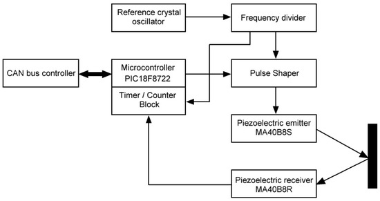
Figure 1.
Block diagram of the ultrasonic single-channel rangefinder.
The ultrasonic navigation system can be divided into a sensor node, which performs a measurement cycle and transmits this information via a communication channel upon request from a sensor node, and a receiving node, which receives information on request from the sensor node and processes the received measurement information [44,45].
Nodes are interconnected by a serial bus CAN (controller area network). In this structure, the receiving node is the “master” controller.
The sensor node is a type of classic pulse locator. The microcontroller (MC) PIC18F8722 (Microchip Technology Inc., Chandler, AZ, USA) [46] generates with an interval of 0.1 s a start pulse that simultaneously starts a pulse packet generator and a 16-bit time interval counter (one of the time counters implemented into the MC). The pulse packet generator generates a pulse packet with a duration of 0.1 ms and a frequency of 40 kHz.
The emitted ultrasonic signal is reflected from an object and returns to the piezoreceiver. The front of the first received pulse stops the time interval counter and generates a signal for finishing the measurement cycle. Upon receiving this signal, the MC reads the code recorded by the counter. The frequency divider generates signals with different frequencies required for the operation of functional blocks in the rangefinder. In the developed device, pulses with a period of 1 μs (frequency of 1 MHz) are sent to the counter to count time intervals.
Since the sensor node is a classic pulse locator, it is necessary to take into account the ambient temperature when measuring the distance with the ultrasonic rangefinder. If the temperature dependence of the ultrasound speed in the air is not taken into account, then when the ambient temperature deviates by 1 °C, an absolute error of approximately 0.6 m/s occurs, which leads to a relative error in the distance measurement of approximately 0.175%.
This paper presents a functional ultrasonic rangefinder for a mobile robot with the correction of climatic instabilities in the environment using ANN. Such a rangefinder has a measurement range, resolution, and performance at the level of modern samples of similar measuring instruments. The rest of this paper is structured as follows. In Section 2, we present the theoretical basis for determining the ultrasound velocity in air and investigate the effect of environmental factors such as temperature, pressure, humidity, wind speed, and wind direction on the ultrasound velocity in air. In Section 3, we present the results of experimental studies of the influence of certain environmental factors on the accuracy of ultrasonic measurements when using a mobile robot indoors and outdoors. The results are discussed in Section 4. Finally, in Section 5, we present the main conclusions.
2. Materials and Methods
2.1. Theoretical Basis of Ultrasonic Speed in Air
According to the laws of classical aerodynamics, the ultrasonic speed in air is determined by the equation , where T is the absolute temperature (K), or by the empirical equation , where t° is the centigrade temperature (°C) [47,48]. However, the latter is used for a wide temperature range (−100…+200) °C, which leads to an increase in the calculation uncertainty of the ultrasonic speed up to 2.9% at the temperature of −100 °C and up to 3.5% at the temperature of +200 °C.
For the MuRata ultrasonic piezoelectric transducers considered in this study, the operating temperature range is (−30…+80) °C [49]. Therefore, the temperature dependence of the ultrasonic speed in the air in this range was proposed to be approximated by the linear regressive dependence with the average relative approximation uncertainty , where n = 9 is the number of measurements of the ultrasonic speed in air for a wide temperature range (−100…+200) °C; the maximal relative approximation uncertainty , the pair correlation coefficient , where and are the standard deviations of the velocity of air temperature and ultrasonic speed, is the standard deviation due to regression, and the coefficient of determination , that confirms the high accuracy of the obtained linear regression dependence.
The accuracy of the approximation can be increased by narrowing the temperature range to (−10…+30) °C, which corresponds to the temperate climatic zone, here with average and maximal relative approximation uncertainties of 432 ppm and 738 ppm, respectively, at a pair correlation coefficient of 0.999769, which further increases the approximation accuracy.
To take into account the effects of the air humidity W and the atmospheric pressure P (kPa), the concept of the acoustic virtual temperature (1) is introduced [50,51]:
The unaccounted effect of the air humidity at normal atmospheric pressure leads to an absolute uncertainty in determining the ultrasonic speed, which does not exceed 0.5 m/s.
Furthermore, wind may impact the ultrasonic speed, which leads to the drift of the ultrasonic wave and creates the effect of the displacement of the ultrasonic source [52]. The ultrasonic speed is determined using Equation (2).
where is the wind speed and is the angle between the direction of the wind at the observation point and the direction of ultrasound.
Considering the influence of air humidity, atmospheric pressure, and wind, we may express the ultrasonic speed in air in different temperature ranges as Equations (3):
Thus, when implementing the ultrasonic rangefinder, the most important factor that impacts the accuracy of the ultrasound speed evaluation is the accurate temperature measurement in the measurement zone, i.e., the distance to the object is determined from Equation (4).
where is the number of counting pulses calculated by the time counter of MC and is the period of counting pulses.
In the second approximate part of Equation (4), the influences of the relative air humidity and atmospheric pressure were not taken into account. If the environmental factors deviate sufficiently from their nominal values (65% and 100 kPa) by 35% to 100% (relative humidity) and by 10 kPa to 90 kPa (atmospheric pressure) at a temperature of 20 °C, the ultrasonic speed will change by 0.523 m/s, which will cause a relative error of 0.15% in the distance determination.
Specifics of ultrasonic measurements at different distances are as follows. At long distances to the target, the reflected signal decreases to a noise level, and the energy potential of the rangefinder becomes the most decisive factor. It is specified with the energy of a probing signal, the effective width of a piezoelectric emitter, the diameter and acoustic properties of a piezoelectric receiver, the sensitivity of the receiver and amplifier, the efficiency of spatial and amplitude-time selection of a target (the energy of reflected signals from distant objects with a large effective reflecting surface can be much more than the energy of reflected signals from small objects located at short distances).
The range of average distances is limited by the distances for which backscattering noise does not affect a receiving path and for which angular dimensions of the main target are commensurate with the operating field of the rangefinder. This range is the most convenient for measurements because of the sufficient power of a signal reflected from an object at various interferences.
When measuring short distances, nearby objects give a high level of reflected signal, which overloads the receiving path. This leads to deterioration in the accuracy and resolution of the measurer. This shortcoming is partially compensated by incomplete overlapping radiation patterns of receiving and transmitting channels at short distances, which is characterized by an overlap coefficient of these fields (dependence of the overlap coefficient on the distance is a hardware function of the rangefinder or a geometric factor [53]).
Figure 2 illustrates the formation of the hardware function. At short distances to the object (shadow zone), where the radiation patterns of the transmission and reception channels are not superimposed, the hardware function is . The distances at which the radiation patterns completely overlap are a far zone where . For the intermediate range of distances (a near zone) and .
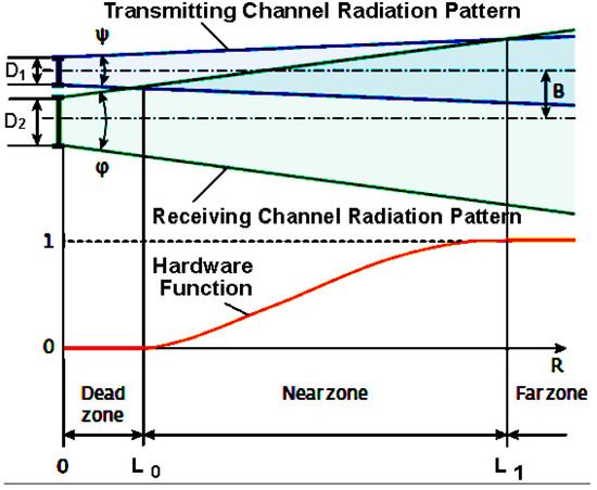
Figure 2.
Principle of forming the hardware function and the shadow zone of the ultrasonic rangefinder D1 is the initial diameter of radiation pattern of the piezoelectric emitter; D2 is the diameter of inlet of the piezoelectric receiver; B is the distance between axes of the transmitting and receiving channels (base); is the hardware function; φ is the opening angle of radiation pattern of the receiving and ψ transmitting channel: ψ is the opening angle of radiation pattern of the transmitting channel.
At the classical construction of the ultrasonic rangefinder, the shadow zone has a value of (0.02…0.2) m, which depends on the mutual configuration of the transmitting and receiving channels.
The requirements for the minimal measured distance and the accuracy of measurements are contradictory because the former requires reducing the shadow zone of the rangefinder, and the latter requires reducing the level of congestion in the receiving path by the reflected signals. This places conflicting demands on the hardware function.
According to the location equation, the intensity of the signal received by the piezoelectric receiver E2 is inversely proportional to the square of the distance L Equation (5):
where P is a constant coefficient (potential), determined by the design and characteristics of the rangefinder; is the overlap coefficient of the radiation patterns of the receiving and transmitting channels; is the attenuation coefficient of ultrasonic radiation on the probing path.
The intensity of the signal received from the farthest object (distance ) should be sufficient for the operation of the piezoelectric receiver with real sensitivity Equation (6):
At constant values of the coefficients and , the intensity of the signal reflected from an object will be greater for distance D than the threshold value for times, which is the value of potential overload of the receiving path. The actual overload considers the hardware function as in Equation (7).
As the base B increases between the receiving and transmitting channels, the level of overload decreases, but the radius of the shadow zone increases.
The distance limits of the rangefinders stated by manufacturers are quite conditional. The quality and ability to measure depend on many factors, and maximal results can be achieved only in the presence of the following: a large object; the surface of the object is smooth, dense, flat, and located perpendicular to a measuring line; the atmosphere is transparent, there is no precipitation, no wind, no strange objects in the path of the ultrasonic wave. In an ideal case, the rangefinder is fixed on a tripod, the piezoelectric transducers are clean, and the batteries are charged. These factors equally affect all ultrasonic rangefinders from different manufacturers, which is why most of them develop special modes to circumvent negative factors, but their impact cannot be avoided completely.
In the presence of noise in channels of the ultrasonic rangefinder, there is a random component of uncertainty that can be estimated by the following expression (8) [54]:
where and are the RMS noise values in the channels of the ultrasonic rangefinder; or are the ratio of signal power to interference power in the channels of the ultrasonic rangefinder; is the phase shift, which is determined by the time delay of the signal propagation in the channel.
To identify the structure of noise in measuring instrument channels, a previous study [41] proposed the use of the Allan variance method.
2.2. Environmental Factors
Three-dimensional and two-dimensional ultrasonic sensors were applied to estimate the speed and direction of wind. The three-dimensional sensors provide data on the direction of flow movement in three components. The two-dimensional sensors estimate the direction and speed of wind only in a horizontal plane [55,56]. Other variations in the implementation of wind speed measurement devices are considered in [57,58].
In the developed ultrasonic rangefinder, an ultrasonic sensor of the WMT700 type manufactured by Vaisala WINDCAP (Vaisala Oyj, Vantaa, Finland) was proposed to be employed for measuring wind characteristics [59]. The sensor includes a built-in microcontroller, which derives and processes data and then transmits them via serial interfaces. The wind sensor consists of three ultrasonic transducers equidistant from each other, located in a horizontal plane (Figure 3a).
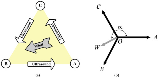
Figure 3.
Operation of the ultrasonic wind sensor (a) and schematic of the sensor (b): A, B, and C are emitters and receivers of ultrasound located at the corners of an equilateral triangle, W is the wind direction, O is the centre of the coordinate system (axis of the WMT700 sensor).
The speed and direction of wind can be estimated by the time needed for the ultrasound to pass from one transducer to the other two. The wind sensor quantifies the ultrasound transit time (in both directions) across the three sides of the triangle of transducers. The transit time is contingent on the wind speed along the ultrasonic path. At zero wind speed, the ultrasound transit time in both directions will be the same. In the presence of wind along the trajectory of ultrasound propagation, the transit time changes: it increases for the movement against the direction of the wind and decreases for the movement in the direction of the wind. The built-in microcontroller calculates the wind speed by the measured ultrasound transit time by the following Equation (9) [59]:
where is the distance between the two transducers, and are the ultrasound transit times in the forward and reverse directions.
A sixfold measurement of the ultrasound transit time is required to calculate the wind speed for each of the three trajectories. The wind speed values by two trajectories are sufficient to determine the wind speed and direction.
The WMT700 wind sensor derives the wind speed as two scalar speeds, one of them is parallel to the north–south direction, and the other is parallel to the west–east direction. Speed can be measured in miles per hour, kilometers per hour, knots, and meters per second. The polar wind direction is expressed in degrees (°). North is marked as 0°, east as 90°, south as 180°, and west as 270°.
Let us transform the layout of the ultrasonic transducers (Figure 3b) for more convenient writing the system of equations, where a vector between points OW is the wind speed vector, α is the angle between the wind speed and the OA vector clockwise. The ultrasound transit time between points B and A is denoted as , between points A and C, it is denoted as , and between points C and B, it is denoted as . The length of the side of the triangle (the distance between points B and A, A and C, C and B) was previously indicated using . The angle between the vectors OA and OB is 2π/3, and the angle between the vectors OA and OC is 4π/3. Considering the Doppler Effect from the ultrasound passing through a moving medium, let us write the following system of Equation (10):
Upon solving the system of Equation (10), we retrieve equations for the speed of ultrasound (11) and wind (12) and for the angular direction of the wind α (13):
Thus, it is possible to assess the wind speed, and its direction can be estimated using the triangular sensor construction by the results of measurements of the ultrasound transit time between the piezoelectric transducers of the sensor, according to Equations (12) and (13). These estimated values can be taken into account when constructing the mobile robotic technical vision system.
Since the ultrasonic speed was estimated in various climatic conditions to solve the navigation problems of mobile robotics, the impact of the group of environmental factors on the output signal of the ultrasonic emitter was investigated for two cases—when the ultrasonic speed was estimated outdoors and indoors. Such environmental factors were investigated: air temperature , atmospheric pressure , and relative humidity . These quantities can be measured using microelectronic components and applied to increase the accuracy of the navigation system of the mobile robot. A correlation analysis was performed, and partial correlation coefficients were calculated considering the results of n = 256 measurements performed over 3 months. The partial correlation coefficients represent the degree of influence on the output signal from the ultrasonic emitter for each climatic factor separately. The significance was estimated according to the ratio of the value of Student’s t-test, calculated by the formula , where is Student’s coefficient, which determines the deviation of means from the general average in units of standard deviation, is the level of correlation, and the table value of Student’s t-test for and significance level .
2.3. Ultrasonic Rangefinder Prototype
To confirm the operability of the suggested algorithm of the sensor node operation (Figure 1), its breadboard was tested. The CAN bus controller MCP2510 (Microchip Technology Inc., Chandler, AZ, USA) is used as the interface for communication with the “master” controller. The MuRata piezotransducers MA40B8S and MA40B8R are used as emitters and receivers of ultrasonic vibrations. Blocks of the frequency divider and the impulse pack shaper are implemented on a programmable logic integrated circuit (PLIC) MAX EPM7128SLC84−7 (Altera Corporation, San Jose, California, USA) (Figure 4a).
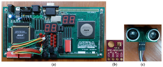
Figure 4.
The printed circuit board of the sensor node (a), an environmental sensor of the BME280 type (b), and the ultrasonic transceiver (c).
A WMT702 wind sensor is applied in the ultrasonic rangefinder to take into account the effects of wind speed and direction when estimating the movement parameters in accordance with Equation (4). The wind sensor has a wind speed measurement range of (0…65) m/s, a 0.01 m/s starting threshold, a 0.01 m/s resolution, a 0.25 s response time, and an accuracy of reading of ±0.1 m/s (0.2 mph) or 2%, whichever is greater [59]. When the wind direction was measured in a (0°…360°) range, the resolution was 0.1°, the response time was 0.25 s, and the accuracy was ±2°.
To consider the influence of environmental factors in determining ultrasonic speed according to Equation (3) and the distance to obstacles, the developed ultrasonic rangefinder employs an integrated environmental sensor of the BME280 type (Figure 4b). It was designed specifically for mobile devices, and its size (2.5 × 2.5 × 0.93 mm) and low power consumption (up to 3.6 μA at a supply voltage (1.7 ÷ 3.6) V) are its key features [60]. The device has a relatively short response time of 1 s and combines three highly linear accurate sensors:
- A low-noise sensor for measuring temperature in the range (−40…+85) °C with a resolution of ±0.1 °C and a maximal absolute uncertainty of ±0.5 °C for the temperature compensation of pressure and humidity sensors;
- An absolute barometric pressure sensor for the range (30…1100) kPa with a maximal relative uncertainty of ±1% and a sensitivity uncertainty of up to ±0.25%;
- A humidity sensor with hysteresis up to 2% of the relative humidity and a maximal absolute uncertainty of ±1%.
In the breadboard of the system, only one ultrasonic channel was used. A breadboard, the “ASK Lab” controller with the additionally installed interface controller CAN MCP2510 (Microchip Technology Inc., Chandler, AZ, USA), was used as the “master” controller. This node is used to test and debug the sensor node. The breadboard includes the bus controller CAN MCP2510, microcontroller PIC18F8722, and character liquid crystal indicator (LCI).
During operation, the “master”-controller and sensor board exchange data via the CAN bus. The MC periodically generates a data request, receives data from the sensor node, and displays the information received on the indicator. The indicator also displays information about the test burst of the sensor node.
When a data request command is received, the MC of the sensor node transmits numerical data about the current measured distance. Additionally, the MC periodically transmits (10 times per second) a test message to the “master”-controller to confirm the normal operation of the node.
The software for the MC sensor board and “ASK Lab” breadboard was compiled in MPLAB 8, and the firmware for the PLIC chip was compiled in MAX+ 10.0.
Piezoelectric transducers are installed in special holders on the board, which provide mechanical protection and facilitate the process of installing them on the mobile robot. The ultrasonic transceiver is depicted in Figure 4c.
Consider the case of a normal incidence of an ultrasonic wave from the air with a characteristic impedance of . Here is the air density at a temperature of 20 °C. The ultrasonic wave drops on a flat surface made of the material with a characteristic impedance of , where is the density of the material and is the ultrasonic speed in the material. The reflection coefficient and the sound absorption coefficient in the case of normal incidence of an ultrasonic wave are specified by Equations (14) and (15) [50]:
where is the specific dimensionless wave resistance of the material, expressed in fractions of the wave resistance of air.
Consider the case of oblique incidence of a plane ultrasonic wave on the interface between two media—air and the material. The reflection coefficient and the sound absorption coefficient are specified by Equations (16) and (17) [50]:
where is the angle of incidence, is the angle of refraction, is the relative refractive index of ultrasound, and is the ratio of the densities of the material and air.
The wave resistances of the explored materials are much higher than the wave resistance of air ( for glass, for brick, for dry oak, for dry pine, for cardboard with a thickness of 450 μm). Therefore, for all the materials, the theoretical values of the reflection coefficient , and the theoretical values of the sound absorption coefficient . However, in the case of oblique incidence of the ultrasonic wave, the reflection coefficient decreases, and the absorption coefficient increases. Moreover, the instrumental function and the partial absorption of ultrasound by the reflecting surface material are the factors that increase the resolution and decrease the maximum range.
To conclude, a decrease in wave resistance of the reflecting surface material (a decrease in the material density and/or the speed of ultrasound in it) leads to a decrease in the maximum stable measured range and an increase in the minimum measured range and measurement resolution [61].
Reflection and multipath effects have a significant effect on the accuracy of ultrasonic distance measurement [11]. Formulas (14)–(17) are useful to study the influence of reflection and multipath effects on the accuracy of ultrasonic distance measurement in a room. In practice, filtering methods [4,56] (e.g., a median filter [13] or a Kalman filter [2,57]) and the data averaging method [33] are used to reduce the influence of reflection and multipath effects on the accuracy of ultrasonic distance measurement. First, echo detection algorithms are also widely used in practice [27,38].
First-reflection algorithms are important for improving the accuracy of ultrasonic rangefinders in the presence of multipath effects [27]. The use of such algorithms makes it possible to identify and process the first reflected pulse of the ultrasonic signal, which corresponds to the direct distance to the obstacle. As a result, delayed pulses corresponding to waves reflected from other surfaces because of multipath effects are ignored. In practice, the following basic algorithms for processing ultrasonic signals to detect the first echo are widely used.
- Threshold detection algorithm. The principle of its operation is to detect the very first signal that exceeds the set amplitude threshold (amplitude threshold method) [27]. The threshold detection algorithm is used in simple environments with a minimum number of reflections [27]. The advantages of the threshold detection algorithm are its simplicity of implementation, low computational complexity, and high signal processing speed. The disadvantages of the threshold detection algorithm are high sensitivity to noise and random interference and the difficulty of setting the amplitude threshold for different surface reflectivity conditions of different materials.
- Peak detection algorithm. The principle of operation is to analyze all received signals and find the first clearly defined peak with maximum amplitude. The peak detection algorithm is used in environments with a large number of reflections where it is necessary to distinguish between real and false signals. The advantages of the peak analysis algorithm are lower sensitivity to small noise and better accuracy with complex reflections. The disadvantages of the peak analysis algorithm are increased processing power and a high probability of missing weak but real signals.
- Cross-correlation detection algorithm. The principle of operation is to compare the received signal with a reference pulse shape using correlation analysis [27,38]. The cross-correlation algorithm is used for high-accuracy measurements in complex environments [27]. The advantages of the cross-correlation algorithm are its high resistance to noise and multipath effects and its ability to accurately identify signals even at low amplitudes [38]. The disadvantages of the cross-correlation algorithm are high computational complexity (the slowest real-time algorithm) and the need for high-precision calibration of the reference signal for different measurement conditions.
- Adaptive threshold detection algorithm. The principle of operation is to dynamically adjust the amplitude threshold depending on the background noise level and previous measurements and to select the first signal that consistently exceeds the adjusted threshold. The adaptive threshold detection algorithm is used to improve measurement accuracy in changing environmental conditions or complex acoustic situations. The advantages of the adaptive threshold detection algorithm are reduced false alarms because of the noise and flexibility in different environments and conditions. The disadvantages of the adaptive threshold detection algorithm are the need to calibrate the adaptation parameters and the high complexity compared with static methods.
- Statistical detection algorithm. The principle of operation is to analyze several echoes and use statistical methods (e.g., median or average) to select the most likely first echo. The statistical processing algorithm is used in high-precision measurement systems or difficult acoustic conditions. The advantages of the statistical processing algorithm are high accuracy with large amounts of noise and resistance to random reflections. The disadvantage of the statistical processing algorithm is slow processing time due to the need to collect statistics. For this reason, the statistical processing algorithm is not used for real-time or high-speed systems.
The results of the comparative analysis of these algorithms for processing ultrasonic signals to detect the first echo signal are shown in Table 2.

Table 2.
Comparative analysis of ultrasonic signal processing algorithms for first echo detection.
After the tests were completed successfully, the developed module was tested under operating conditions as part of a simplified version of a collision avoidance system. The aim of the experiment was to test the operability of an ultrasonic part of the device under real operating conditions.
2.4. Neural Network Development for Error Correction
The complex uncertainty of MR motion measurement systems and the accumulation over time determine the application of artificial neural networks as a means for reducing the value of this uncertainty [12]. Another approach is to use traditional error correction methods such as linear regression or polynomial models. Comparing ANN with traditional regression-based corrections such as linear regression or polynomial models involves examining their structure, capabilities, and performance in various contexts. Table 3 provides a high-level overview and comparison of ANN and traditional regression methods.

Table 3.
Results of comparison between ANN and traditional regression methods.
The choice between ANN and traditional regression methods depends on the specific problem, the nature of these data, and the desired result. For complex, non-linear relationships and large data sets, ANNs are more appropriate. The task of the neural network is to approximate a non-linear relationship between data of the navigation system MR and real data (coordinates of the MR, calculated on data from sensors of the navigation system, and reference values of the real position of the robot).
Whereas input parameters are measured cyclically, we will consider ANNs of feed-forward (FF) and cascade-forward (CF) types [62].
The number of input and output parameters in the ANN depends on an approximation problem, and the number of hidden layers depends on the type of non-linear relationships between the parameters [18]. When determining the distance to the obstacle with the ultrasonic rangefinder, the output parameter is the distance, and the input parameters are temperature, relative humidity, atmospheric pressure, the number of pulses calculated by the microcontroller counter, and the period of the counting pulses.
ANNs of CF type are structurally similar to FF networks, but they are more complex for construction and implementation. They have not only a series of informational connections between layers but also cascading connections of previous layers with the following ones. Such networks are usually taught with a supervisor, i.e., with representative samples of input and output data by the method of uncertainty backpropagation.
A small number of neurons in ANN layers leads to problems with the specification of non-linear connections, and an excessive number enhances the complexity of the network and the time of calculation and training. In addition, a large number of neurons usually leads to “retraining” (excessive training or excessive adaptation to a training sample) of ANNs, which negatively affects the accuracy of determining an initial value. Therefore, to study the efficiency of ANNs, the number of neurons was selected experimentally from 4 to 18.
Each of the experimental databases for training and testing of the ANN was divided into two separate samples: to determine the weight values and to independently evaluate the effectiveness of the ANN operation on additional data that were not utilized in the training process.
To study the possible error of wheeled MRs, the UMBMark method was utilized. The UMBMark method was proposed in [63]; it was based on the analysis of a robot movement on the sides of a square with dimensions of 4 m, and different algorithms were applied to evaluate the quality of such movement. However, this method is difficult to implement and may yield inaccurate results when investigating small MR images. Therefore, to collect data for experiments, the MR moved in a straight line with speeds of 0.25 m/s, 0.5 m/s, and 0.75 m/s, and the movement time was chosen so that the MR movement was approximately (3… 5) m. Data from the ultrasonic rangefinder with a frequency of 5 Hz were read as the MR was moving, and the endpoint of the movement was fixed by external measurements. Ten intermediate positions of the MR were calculated considering data obtained from the ultrasonic rangefinder.
A sample of 256 control values was created to investigate the relationship between these parameters. The relationship is complex and depends on many factors that are difficult to establish analytically.
ANN models of FF and CF types were developed and analyzed to calculate the distance to obstacles with high accuracy according to the number of counting pulses and the ultrasonic speed in the air. The characteristics of the non-linearity and complexity of the relationship between parameters were unknown, so the number of layered layers, neurons in the layers, and neural activation functions were chosen experimentally. As a result, a set of ANNs of different structures was created and analyzed.
The uncertainty backpropagation method was used for training [26]. The root mean square value of uncertainty is calculated by Equation (18).
where K is the size of the training sample and is the reference coordinate of the real position of the robot.
The coordinates of the robot’s real position are used as reference values for training the ANN. The coordinates are estimated using two approaches: video registration by the camera and manual measurement. An attempt was made to measure the real position using infrared rangefinders, but errors in these data did not allow us to draw conclusions about the real quality of the neural network. Thus, for training the neural network, a training sample with a total size of K = 256 was prepared, from which a sample of size 40 was actually used for training and testing.
The training was performed in the neural network toolbox of the MATLAB version R2014b programming platform using the trainlm function (according to an algorithm that modifies weights and shifts by the Levenberg–Marquardt optimization method [55]). The criterion for the training effectiveness was the standard uncertainty, and the maximum number of epochs was 1000 without a time limitation for the process.
Using the multilayer perceptron and Catboost models [64], it is possible to improve the accuracy of the MR navigation system’s measurement information.
3. Results
3.1. Effect of Individual Environmental Factors on Ultrasonic Accuracy
When parameters of the object movement are measured, the most important nominal values that affect the result are: temperature of 20 °C (293 °K); ambient pressure of 99.992 kPa (750 mm Hg); relative air humidity of 65% (normal partial pressure of water vapor 1351 Pa). This means that the acoustic virtual temperature is Equation (19).
Moreover, unaccounted relative air humidity and atmospheric pressure may cause a temperature deviation of 2.62% from the nominal value, which leads to a relative error of 0.1% in determining the ultrasonic speed in the air.
Figure 5 illustrates the surfaces describing the dependence of the ultrasonic speed in air on temperature and atmospheric pressure at a nominal relative humidity of 65%. The influence of the relative air humidity in Figure 5 is not evaluated, as it is statistically insignificant both outdoors and indoors (it will be shown further in Table 1). An increase in atmospheric pressure in the (80–120) kPa range leads to a decrease in the ultrasound speed by 0.107 m/s at a temperature of −30 °C and by 0.156 m/s at a temperature of +80 °C. A much more important factor is the effect of air temperature. Thus, at an atmospheric pressure of 99.992 kPa, an increase in air temperature in the (−1…+30) °C range leads to an increase in the ultrasound speed by 23.722 m/s, and in the (−30…+80) °C range, it leads to an increase in the ultrasound speed by 64.356 m/c. The effect of climatic parameters on the ultrasonic speed in the air in the ranges is described with close to linear dependences.
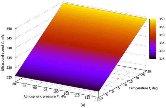
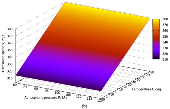
Figure 5.
Dependences of the ultrasonic speed in the air on the temperature in the ranges (−10…+30) °C (a) and (−30…+80) °C (b), the change in atmospheric pressure from 80 kPa to 120 kPa at a relative humidity of 65%.
Figure 6 shows the surface describing the dependence of the determined distance on the ambient temperature and the number of pulses counted by the counter . The influence of relative air humidity and atmospheric pressure in Figure 6 is not estimated.
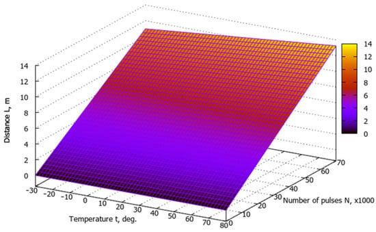
Figure 6.
Dependence of the distance on the ambient temperature and the number of pulses counted by the microcontroller counter.
With the number of pulses being , an increase in air temperature in a (−10…+30) °C range causes an increase in the determined range by 0.355 m, while that in a (−30…+80) °C range causes an increase in the determined range by 0.977 m. Nevertheless, the impact of the number of pulses, i.e., the measurement time, is a much more important factor. Thus, at the air temperature of +20 °C, an increase in the number of pulses in a range of (10…60)·103, as well as an increase in the measurement time in a (10…60) ms range, leads to an increase in the determined range by 8.578 m, and at the air temperature of +80 °C, an increase in the number of pulses in the same range leads to an increase in the determined range by 9.466 m.
The potential resolution of the ultrasonic rangefinder at a temperature of 20 °C is [43]
where is the ultrasonic speed in the air at 20 °C; is the minimal measured number of count pulses.
The maximal detectable distance is limited by the power of the piezoemitter and equals 6 m. If the 16-bit counter counts the maximum number of 216 pulses, it stops and generates a signal of finishing the count, so the maximal time to measure the distance is and the maximal detectable distance is .
The results (Table 4) show a close relationship between the environmental factors investigated and the output signal of the piezoelectric emitter. The air temperature maximally affects the output signal in both cases; however, in outdoor studies, the effect is more significant. The effect of atmospheric pressure on the output signal is weak and inverse outdoors and is statistically insignificant indoors. The impact of relative humidity , both outdoors and indoors, is statistically insignificant.

Table 4.
Partial correlation coefficients and evaluation of their significance.
Considering the experimental studies of determining ultrasonic speed, the relative air humidity can be regarded as constant outdoors and indoors, and the atmospheric pressure can be regarded as constant indoors. Then, relation (1) for estimation of the ultrasonic speed at different temperatures is as follows:
- -
- Estimation of the ultrasound speed outdoors:
- -
- Estimation of the ultrasound speed indoors:
Thus, we must consider that the output signal of the piezoelectric emitter is very strongly affected by a change in air temperature, while atmospheric pressure and relative humidity are less significant. Therefore, the navigation system must include sensors to measure climatic parameters to use them to improve the accuracy of navigation and time definition.
The maximal absolute uncertainty in calculating the ultrasonic speed in the air at the edges of the temperature range from the readings of this integrated sensor can be determined by Equations (23):
The computed absolute uncertainty in calculating the ultrasonic speed in the air at the maximal uncertainty of the integrated sensor causes a relative uncertainty of less than 0.1%, which, according to Equation (4), leads to an absolute error in estimating the distance of less than 6 mm (for maximal piezo emitter power).
3.2. Ultrasonic Rangefinder Prototype Performance
A rangefinder was developed for field trials. It was implemented on a Robotino v2-type wheeled robot with a remote control, on which the ultrasonic transceiver was installed (Figure 7). The collected information is transmitted in real-time and recorded on a PC for further analysis. The robot’s movement was controlled remotely.
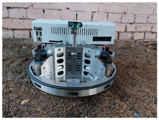
Figure 7.
Field trials of the robot Robotino v2 type.
The system provides remote control of the robot’s movement by operator commands. A collision avoidance subsystem continuously measures the distance to obstacles in front and behind. If any of these distances are less than a threshold, then the robot stops immediately, and the control is blocked. This provides protection against collisions with obstacles.
A personal computer (PC) is used for the forced control of the robot.
To exchange data with the main module of the ultrasonic rangefinder and the robot controller, specialized high-level software was developed, which provided the following functions [65]:
- -
- request and reception of distance data from the ultrasonic rangefinder;
- -
- analysis of obtained data and comparison of the distance to the object with a threshold;
- -
- emergency stop when receiving a distance less than the threshold.
The Robotino v2 robot remote control kit was utilized to perform the experiments. The control signal is a burst of six pulses. The pulse duration varies in the range of (0.6 ÷ 1.6) ms, and the pause duration between pulses is 1.5 ms. After transmission of the pulse packet (20 ms), a new packet is formed according to the current position of the control knobs. One of the built-in microcontroller timers is used to count time intervals.
A transmitter and receiver complex was installed on the front of the robot to measure the distance to objects. The main module of the rangefinder is powered by a 12 V battery of the robot through a 12 V−5 V voltage converter module. The output bridges of the robot motors are powered by a separate set of 12 V batteries.
During field experiments, the robot was directed to a brick wall at a speed of 3 m/s. At first, it moved forward and then backward. After reaching a threshold distance of 0.8 m, the robot stops at a distance of approximately 0.2 m, i.e., the reaction time of the system was 0.2 s.
To verify the operability of the ultrasonic rangefinder, some tests were performed. During these tests, the distance to various objects was determined, and a result was observed on the indicator of the receiving node (Figure 8). Objects with different reflection coefficients of ultrasound (glass, brick, wood, cardboard, and fabric) were used as obstacles.
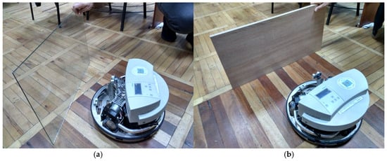
Figure 8.
Testing the ultrasonic rangefinder with the glass obstacle (a) and wood obstacle (b).
The testing results confirmed the operability of the device. During testing, the technical characteristics of the rangefinder were estimated for various reflective surfaces (Table 5).

Table 5.
Experimental characteristics of the ultrasonic rangefinder.
The obtained results correspond to the theoretical results for well-reflecting surfaces, and the maximal detection distance of obstacles depends on the surface reflection coefficient, i.e., on the material that covers the obstacle.
The investigation has shown that the CAN bus had several advantages, such as the simpler hardware implementation of addressing, bus arbitration, etc. Therefore, it was concluded that the CAN bus was more promising for implementing the on-board network in the mobile robot [66].
3.3. Neural Network Performance
According to the results of developed models of the FF type with one hidden layer, the best results based on the criterion of maximum accuracy were obtained using the ANN. The structure of the ANN is shown in Figure 9.
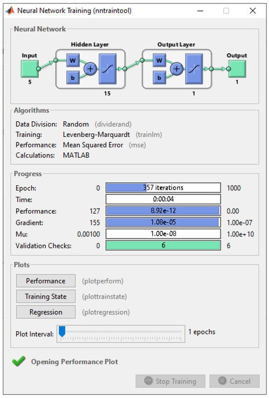
Figure 9.
Feed-forward ANN training.
During the investigation, the number of neurons in the hidden layer varied from four to eighteen. When the number of neurons increased to 16, the ANN showed unsatisfactory results on these new data. The training of the network lasted 357 epochs.
During the investigation of the cascade ANN of the CF type, the maximum accuracy in training was provided in the network with the structure shown in Figure 10. The ANN was trained in six epochs. According to the analysis, the cascade-forward ANN showed better results than the feed-forward ANN.
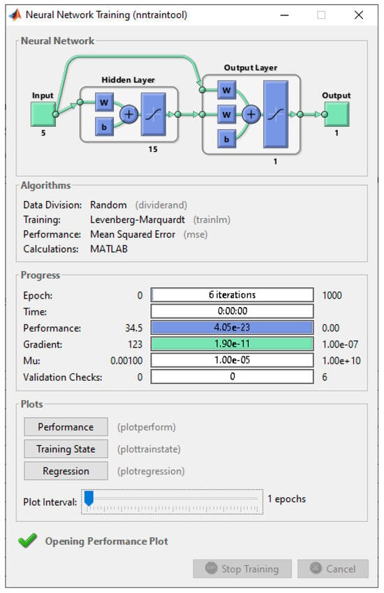
Figure 10.
Cascade-forward ANN training.
As the computational characteristics of the considered ANN are not high enough, they should be optimized for real-time operation in mobile robotic systems. Therefore, the authors optimized the parameters of the ANN for its real-time implementation and simulated it using Matlab software.
Table 6 presents the numerical values of parameters used for training and testing the suggested ANN. These data were split into three groups: training (used at a 75% ratio), testing (10%), and validation (15%).

Table 6.
Data for ANN training and testing.
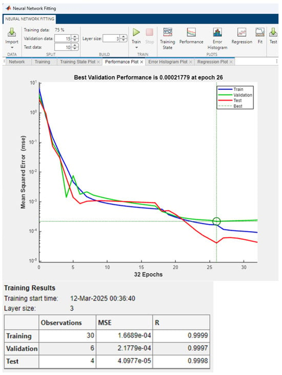
Figure 11.
Results of training the optimized ANN.
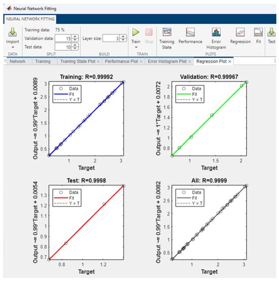
Figure 12.
Results of testing the optimized ANN.
The obtained quantitative ANN performance indicators are shown in Table 7.

Table 7.
MSE and RMSE values for training, validation and testing data.
The implementation of the neural network designed for the mobile robot as an integrated system is based on programming synaptic weights of the hidden layers, synaptic weights of the output layer, bias or weights of each layer, and knowledge of the activation functions that are used in each of the layers. The ultrasonic sensor is placed inside the mobile robot, and its signals operate as the network’s inputs. Decimal numbers form the network output.
To ensure high speed and the ability to operate in real-time systems, in which the timing of events is a priority, the developed artificial neural network must be implemented either on a specialized microprocessor or on a PLIC, which performs parallel information processing.
The authors performed experiments to determine the root mean square error (RMSE). The tests were performed indoors under normal environmental factors (temperature 20 °C, relative humidity 65%, atmospheric pressure 101.3 kPa) with no airflow. The laboratory is 6 m wide and 12 m long, with a ceiling height of 3.75 m. The floor is a wooden parquet. The mobile robot, type Robotino v2, was placed motionless on the floor. The authors used glass perpendicular to the floor as a reflective surface. The ultrasound transducer was placed horizontally on the Robotino v2 type mobile robot mount at a height of 32 cm from the floor with its central radiation axis perpendicular to the central axis of the glass reflecting surface to minimize the deviation in the ultrasound signal. Using the proposed method, the authors measured three distances of 0.5 m, 1.2 m, and 2.0 m. The authors performed 400 measurements for each distance. Based on experimental data, the authors determined numerical RMSE values of 6.962 mm, 7.016 mm, and 7.083 mm, respectively. Based on the results of the experiment, the authors found that the numerical value of the RMSE is almost independent of the measured value in the measurement range.
Table 8 demonstrates a comparison of the main technical parameters of mobile robot ultrasonic rangefinders.

Table 8.
Comparative analysis of ultrasonic rangefinders for mobile robots.
Considering the results of the comparative analysis, we conclude that the parameters of the developed device are at the level of the best modern samples.
To extend the distance measurement range, minimal scattering of the emitted signal, an increase in the excitation voltage of the piezoelectric emitter, or the use of the most advanced types of piezoelectric sensors are required. The potential resolution value can be achieved by minimizing the noise level, using correlation signal processing and optimal filtering. Neural network processing of measurement information improves the technical characteristics of the ultrasonic rangefinder but requires additional research on training the neural network, its adaptation to environmental conditions, and the exclusion of anomalous measurement results.
4. Discussion
This study highlights the significant effect of environmental factors on the accuracy of ultrasonic rangefinders in mobile robotic technical vision systems. The results indicate that temperature, relative humidity, atmospheric pressure, and wind significantly impact the propagation speed of ultrasonic waves in the air, as well as the performance of the piezoelectric emitter and ultrasonic rangefinder.
The results demonstrate that air temperature exerts the most substantial influence on ultrasonic speed, as evidenced by the partial correlation coefficients and statistical tests conducted on 256 measurements. The temperature dependencies derived over the ranges of (−30…+80) °C and (−10…+30) °C provide critical insights for real-world applications. Conversely, relative humidity and atmospheric pressure were found to have minimal effects on the piezoelectric emitter output signal, with atmospheric pressure displaying a weak reversed effect outdoors and a statistically insignificant effect indoors. These findings suggest that, when operating indoors, relative humidity and atmospheric pressure can be approximated as constant, simplifying the modeling and calibration processes.
The integration of environmental sensors, such as the BME280 and WMT700 sensors, in the ultrasonic rangefinder prototype proved effective in compensating for environmental influences. The BME280 sensor accounted for variations in temperature, humidity, and pressure, while the WMT700 wind sensor provided precise data on wind speed and direction. This integration highlights the importance of utilizing environmental sensors to improve the robustness of ultrasonic rangefinders in dynamic, real-world environments.
Experimental results validated the theoretical findings for highly reflective surfaces, revealing that the maximum detection range is heavily influenced by the reflection coefficient of obstacle surfaces. This dependence underscores the importance of considering material properties when designing and calibrating rangefinders for specific applications.
The developed cascade-forward artificial neural network demonstrated strong potential for improving localization accuracy in mobile robotics. The ANN effectively corrected environmental errors, enabling the precise determination of obstacle positions and enhancing the reliability of the rangefinder in diverse environmental conditions. However, the computational demands of the ANN must be optimized for real-time operation in mobile robotic systems.
The MR navigation system yields estimates of navigation parameters such as motion parameters and orientation angles. The estimates are subject to two types of interference: high-level (emissions, signal dropouts) and low-level (instrumental and other types of errors). To combat these, a two-stage processing procedure is used [70]. In the first stage, high-level interference is eliminated using a block of median or diagnostic filters. Median filters with a window length of k = 3 are used to exclude single faults. In general, the window length k = 2n + 1 ensures insensitivity to n failures. In the second stage, a Kalman filter is used to deal with low-level disturbances, the output of which is the navigation parameter estimates ‘cleaned’ of disturbances [41].
To improve the accuracy of ultrasonic distance measurement in rooms, taking into account the phenomenon of reflections and multipath effects, it is necessary to use ultrasonic signal processing algorithms to detect the first echo [68]. As shown in Table 2, threshold detection or peak analysis algorithms are effective for simple environments with a minimum of reflections. For complex environments or conditions, cross-correlation or adaptive threshold detection algorithms are effective.
These findings contribute to the broader understanding of environmental factor mitigation in ultrasonic sensing and highlight the potential of combining environmental sensors and machine learning to enhance the accuracy and reliability of robotic vision systems.
5. Conclusions
In this paper, the authors investigated the effect of ambient temperature, atmospheric pressure, relative humidity, wind speed, and direction on distance measurement using an ultrasonic rangefinder. Using the concept of virtual temperature, the authors proposed new approximation equations for calculating the ultrasonic velocity for the temperature ranges −10 °C…+30 °C and −30 °C…+80 °C depending on the value of temperature, pressure, and humidity, taking into account the effect of wind speed and direction. The authors have developed an experimental model based on the Robotino v2 type mobile robot, whose movement speed is less than 3 m/s. To take into account the influence of wind speed and direction, the WMT702 wind sensor was used. This sensor has a wind speed measurement range of (0…65) m/s, a threshold of 0.01 m/s, a resolution of 0.01 m/s, a response time of 0.25 s, and a reading accuracy of ±0.1 m/s. To take into account the influence of environmental factors, the authors used an integrated environmental sensor of the BME280 type. This sensor measures temperature in the range of (−40…+85) °C with a resolution of ±0.1 °C and a maximum absolute error of ±0.5 °C. It also measures barometric pressure in the range of (30…1100) kPa with a maximum relative uncertainty of ±1% and sensitivity uncertainty of up to ±0.25% and measures relative humidity with a maximum absolute error of ±1%. The sensor unit is a type of classical pulse locator. The MA40B8S piezoelectric emitter and MA40B8R piezoelectric receiver were used. The PIC18F8722 microcontroller generates a start pulse at intervals of 0.1 s, which simultaneously starts the pulse packet generator and a 16-bit time interval counter. The pulse packet generator generates a pulse packet with a duration of 0.1 ms and a frequency of 40 kHz. Pulses with a period of 1 µs (1 MHz frequency) are fed to the counter to count time intervals. To effectively correct measurement errors caused by environmental variations, an artificial neural network with cascade data transmission was developed. As a result, the authors obtained the following numerical values of the ultrasonic rangefinder parameters: distance measurement range 0.08–2.73 m (potentially up to 5.62 m), resolution 1.5 mm (potentially 0.0858 mm), beam width ±30°, RMSE 6.4 mm.
Considering the results obtained in this study, we can draw several conclusions that may be important for developing systems with ultrasonic rangefinders.
- It must be taken into account that the output signal of the piezoelectric emitter is sufficiently affected by changes in the air temperature and less affected by changes in the atmospheric pressure and relative humidity. Therefore, ultrasonic rangefinders should include sensors for measuring climatic parameters to apply them further to improve the accuracy of navigational and time parameters. When the ultrasonic rangefinder operates in the open air, the wind sensors that determine the wind speed and direction may be applied to increase the accuracy of the estimation of motion parameters. These sensors have no moving parts, which increases their reliability, and the minimum number of their piezoelectric transducers reduces the cost. In addition, the algorithm of the WMT700 sensor immediately determines the wind speed and direction in the polar coordinate system, which increases the accuracy of the wind parameter estimation.
- Ultrasonic rangefinders without additional navigation devices (odometers, inertial navigation systems, GPS) should be used if the operating conditions for the system are clearly defined (reflective properties of objects, limits for measuring distance, and climatic parameters in the measurement zone are well-known).
- The application of ultrasonic rangefinders in dynamically changing operating conditions without integration with other types of navigation systems does not guarantee the declared results, especially when robotic systems and systems are employed in field conditions. However, the parameters of other types of rangefinders (video, laser, and others, except radars in the near and middle emitting zones) also depend on the operating conditions. Hence, ultrasonic rangefinders should be used with other types of rangefinders. This allows compensation for the divergence of sensor capabilities and provides a margin of reliability for the whole system.
- The determination of optimal combinations of various types of sensors (ultrasonic, inertial, ultrahigh-frequency, optical, odometric, and others) for using mobile robotics is now of practical interest. The authors believe that combining the results of ultrasonic measurements with data from inertial sensors or a satellite radio navigation system (GPS, Galileo, Beidou, and GLONASS) is promising [41].
- Upon considering the results of the accuracy analysis performed during the computer simulation, we defined a structure of the ANN for the determination of the distance to an obstacle (a current MR coordinate). This structure takes into account the features and complexity of the interrelation between the input and output information parameters in the best way.
In further studies, we will perform experiments in different rooms to analyze how air conditioning, ventilation, and humidity changes at different CO2 concentrations affect ultrasound velocity. Using the proposed approach to estimating ultrasonic velocity from environmental factors, we will also investigate multi-frequency rangefinders and analyze their advantages in reducing errors caused by reflection from different types of surfaces.
Author Contributions
Conceptualization, A.R. and A.S.; methodology, A.R. and P.K.; software, S.B. and O.S.; validation, O.S. and O.K.; formal analysis, S.B. and P.K.; investigation, A.R. and A.S.; resources, P.K. and L.B.; data curation, O.S. and O.K.; writing—original draft preparation, A.R. and A.S.; writing—review and editing, O.S. and L.B.; visualization, O.K. and L.B.; supervision, S.B.; project administration, S.B.; funding acquisition, A.S. All authors have read and agreed to the published version of the manuscript.
Funding
This research received no external funding.
Data Availability Statement
Most data are included in the article. Additional information and data are available from the corresponding author if required.
Acknowledgments
The authors express their profound gratitude to all colleagues and institutions that contributed to the research and facilitated the publication of its results. The authors are particularly grateful to the staff of the Department of Computer Science of Vinnytsia National Technical University and its head, Andrii Yarovyi, for the opportunity to experiment with the Robotino v2 mobile robot.
Conflicts of Interest
The authors declare no conflicts of interest.
References
- Elamin, A.; El-Rabbany, A.; Jacob, S. Event-Based Visual/Inertial Odometry for UAV Indoor Navigation. Sensors 2025, 25, 61. [Google Scholar] [CrossRef]
- Rudyk, A.; Rudyk, V.; Matei, M. Research and simulation of the local navigation system of terrestrial mobile robot. Inform. Automatyka Pomiary W Gospodarce I Ochronie Środowiska 2020, 10, 56–61. [Google Scholar] [CrossRef]
- Zafar, M.N.; Mohanta, J.C. Methodology for Path Planning and Optimization of Mobile Robots: A Review. Procedia Comput. Sci. 2018, 133, 141–152. [Google Scholar] [CrossRef]
- Panigrahi, P.K.; Bisoy, S.K. Localization strategies for autonomous mobile robots: A review. J. King Saud Univ.-Comput. Inf. Sci. 2022, 34, 6019–6039. [Google Scholar] [CrossRef]
- Gang, L.; Wang, J. PRM Path Planning Optimization Algorithm Research. WSEAS Trans. Syst. Control. 2016, 11, 81–86. [Google Scholar]
- Liu, B.; Ding, L.; Wang, S.; Meng, L. Designing Mixed Reality-Based Indoor Navigation for User Studies. KN J. Cartogr. Geogr. Inf. 2022, 72, 129–138. [Google Scholar] [CrossRef]
- Ušinskis, V.; Nowicki, M.; Dzedzickis, A.; Bučinskas, V. Sensor-Fusion Based Navigation for Autonomous Mobile Robot. Sensors 2025, 25, 1248. [Google Scholar] [CrossRef]
- Papa, I.; Lopresto, V.; Langella, A. Ultrasonic inspection of composites materials: Application to detect impact damage. Int. J. Lightweight Mater. Manuf. 2021, 4, 37–42. [Google Scholar] [CrossRef]
- Li, F.; Han, L. Autopilot design for control of Rotorcraft Micro Aerial Vehicles (RMAVs) swarm. In Proceedings of the 2014 IEEE/ION Position, Location and Navigation Symposium PLANS 2014, Monterey, CA, USA, 5–8 May 2014; pp. 1162–1167. [Google Scholar] [CrossRef]
- Przybyla, R.J.; Tang, H.; Guedes, A.; Shelton, S.E.; Horsley, D.A.; Boser, B.E. 3D Ultrasonic Rangefinder on a Chip. IEEE J. Solid-State Circuits 2015, 50, 320–334. [Google Scholar] [CrossRef]
- Tai, H.; Zhang, H. The hardware research of ultrasonic ranging system based on variable emission wavelength. In Proceedings of the 2019 IEEE 4th Advanced Information Technology, Electronic and Automation Control Conference (IAEAC), Chengdu, China, 20–22 December 2019; pp. 1942–1945. [Google Scholar] [CrossRef]
- Karagoz, A.; Dindis, G. Object Recognition and Positioning with Neural Networks: Single Ultrasonic Sensor Scanning Approach. Sensors 2025, 25, 1086. [Google Scholar] [CrossRef]
- Meliones, A.; Filios, C.; Llorente, J. Reliable Ultrasonic Obstacle Recognition for Outdoor Blind Navigation. Technologies 2022, 10, 54. [Google Scholar] [CrossRef]
- Mousa, M.; Oudat, E.; Claudel, C. A Novel Dual Traffic/Flash Flood Monitoring System Using Passive Infrared/Ultrasonic Sensors. In Proceedings of the 2015 IEEE 12th International Conference on Mobile Ad Hoc and Sensor Systems, Dallas, TX, USA, 19–22 October 2015; pp. 388–397. [Google Scholar] [CrossRef]
- Odat, E.; Shamma, J.S.; Claudel, C. Vehicle Classification and Speed Estimation Using Combined Passive Infrared/Ultrasonic Sensors. IEEE Trans. Intell. Transp. Syst. 2018, 19, 1593–1606. [Google Scholar] [CrossRef]
- Van Brummelen, J.; Emran, B.; Yesilcimen, K.; Najjaran, H. Reliable and low-cost cyclist collision warning system for safer commute on urban roads. In Proceedings of the 2016 IEEE International Conference on Systems, Man, and Cybernetics (SMC), Budapest, Hungary, 9–12 October 2016; pp. 003731–003735. [Google Scholar] [CrossRef]
- Răzvan-Daniel, A.; Nicolae, D. Designing a flexible and low cost ultrasonic noncontact rangefinder. In Proceedings of the 2017 14th International Conference on Engineering of Modern Electric Systems (EMES), Oradea, Romania, 1–2 June 2017; pp. 244–247. [Google Scholar] [CrossRef]
- Firmansyah, R.A.; Pambudi, W.S.; Suheta, T.; Zuliari, E.A.; Muharom, S.; Hidayatullah, M.B.S. Implementation of Artificial Neural Networks for Localization System on Rescue Robot. In Proceedings of the 2018 Electrical Power, Electronics, Communications, Controls and Informatics Seminar (EECCIS), Batu, Indonesia, 9–11 October 2018; pp. 305–309. [Google Scholar] [CrossRef]
- Shafiq, M.; Gu, Z. Deep Residual Learning for Image Recognition: A Survey. Appl. Sci. 2022, 12, 8972. [Google Scholar] [CrossRef]
- Haq, F.A.; Dewantara, B.S.B.; Marta, B.S. Room Mapping using Ultrasonic Range Sensor on the ATRACBOT (Autonomous Trash Can Robot): A Simulation Approach. In Proceedings of the 2020 International Electronics Symposium (IES), Surabaya, Indonesia, 29–30 September 2020; pp. 265–270. [Google Scholar] [CrossRef]
- Venkatesan, P.; Pavitra, N.; Mohan, R. Performing SLAM using Low-Cost Sensors for Autonomous Navigation in household environments. In Proceedings of the 2019 IEEE 5th International Conference for Convergence in Technology (I2CT), Bombay, India, 29–31 March 2019; pp. 1–5. [Google Scholar] [CrossRef]
- Zhou, Z.; Yoshida, S.; Tanaka, S. Epitaxial PMnN-PZT/Si MEMS ultrasonic rangefinder with 2m range at 1V drive. Sens. Actuators A Phys. 2017, 266, 352–360. [Google Scholar] [CrossRef]
- Yu, Q.; Fan, G.; Ren, W.; Fan, Q.; Ti, J.; Li, J.; Wang, C. PZT-Film-Based Piezoelectric Micromachined Ultrasonic Transducer with I-Shaped Composite Diaphragm. Micromachines 2022, 13, 1597. [Google Scholar] [CrossRef]
- Pan, J.; Bai, C.; Zheng, Q.; Xie, H. Review of Piezoelectric Micromachined Ultrasonic Transducers for Rangefinders. Micromachines 2023, 14, 374. [Google Scholar] [CrossRef]
- Yang, W.; Li, H.; Gong, Y.; Wang, Z.; Xu, X.; Hu, X.; Niu, P.; Pang, W. Impact of Cell Layout on Bandwidth of Multi-Frequency Piezoelectric Micromachined Ultrasonic Transducer Array. Micromachines 2025, 16, 49. [Google Scholar] [CrossRef]
- Sahoo, A.K.; Udgata, S.K. A Novel ANN-Based Adaptive Ultrasonic Measurement System for Accurate Water Level Monitoring. IEEE Trans. Instrum. Meas. 2020, 69, 3359–3369. [Google Scholar] [CrossRef]
- Lu, Y.; Zhang, S.; Hu, W.; Qiu, Z.; Qiu, Z.; Qiu, Y. Distance Measurement and Error Compensation of High-Speed Coaxial Rotor Blades Based on Coded Ultrasonic Ranging. Micromachines 2025, 16, 61. [Google Scholar] [CrossRef]
- Tonmoy, A.B.R.; Zinan, M.D.S.; Sultan, S.; Sarker, A. A comparative study on LIDAR and Ultrasonic Sensor for Obstacle Avoidance Robot Car. In Proceedings of the 2023 International Conference on Advances in Electronics, Communication, Computing and Intelligent Information Systems (ICAECIS), Bangalore, India, 19–21 April 2023; pp. 582–587. [Google Scholar] [CrossRef]
- Pinto, M.L.; Wehrmeister, M.A.; de Oliveira, A.S. Real-Time Performance Evaluation for Robotics. J. Intell. Robot Syst. 2021, 101, 37. [Google Scholar] [CrossRef]
- Özcan, M.; Aliew, F.; Görgün, H. Accurate and Precise Distance Estimation for Noisy IR Sensor Readings Contaminated by Outliers. Measurement 2020, 156, 107633. [Google Scholar] [CrossRef]
- Shen, M.; Wang, Y.; Jiang, Y.; Ji, H.; Wang, B.; Huang, Z. A New Positioning Method Based on Multiple Ultrasonic Sensors for Autonomous Mobile Robot. Sensors 2020, 20, 17. [Google Scholar] [CrossRef]
- Okonkwo, C.; Awolusi, I. Environmental Sensing in Autonomous Construction Robots: Applicable Technologies and Systems. Autom. Constr. 2025, 172, 106075. [Google Scholar] [CrossRef]
- Li, Q.; Huang, Z.; Zhu, Z. Design of High-Precision Ultrasonic Ranging System for Mobile Robot. In Proceedings of the 2021 IEEE 4th Advanced Information Management, Communicates, Electronic and Automation Control Conference (IMCEC), Chongqing, China, 18–20 June 2021; pp. 1490–1495. [Google Scholar] [CrossRef]
- Li, Q.; Zhu, H. Performance Evaluation of 2D LiDAR SLAM Algorithms in Simulated Orchard Environments. Comput. Electron. Agric. 2024, 221, 108994. [Google Scholar] [CrossRef]
- Wang, H.; Yin, Y.; Jing, Q. Comparative Analysis of 3D LiDAR Scan-Matching Methods for State Estimation of Autonomous Surface Vessel. J. Mar. Sci. Eng. 2023, 11, 840. [Google Scholar] [CrossRef]
- Adams, M.; Jose, E.; Vo, B.-N. Robotic Navigation and Mapping with Radar; Artech: Morristown, NJ, USA, 2012; ISBN 9781608074839. [Google Scholar]
- Rouveure, R.; Debain, C.; Peuchot, R.; Laneurit, J. Robot Localization and Navigation with a Ground-Based Microwave Radar. In Proceedings of the 2019 International Radar Conference (RADAR), Toulon, France, 23–27 September 2019; pp. 1–4. [Google Scholar] [CrossRef]
- Nonsakhoo, W.; Saiyod, S.; Moungmingsuk, N. Angle-of-Arrival Analysis of Multi-Channel Stereo Ultrasonic Signal for Angular Coordinates Positioning. In Proceedings of the 2018 2nd International Conference on Imaging, Signal Processing and Communication (ICISPC), Kuala Lumpur, Malaysia, 20–22 July 2018; pp. 125–131. [Google Scholar] [CrossRef]
- Zheng, S.; Li, Z.; Yin, Y.; Liu, Y.; Zhang, H.; Zheng, P.; Zou, X. Multi-robot relative positioning and orientation system based on UWB range and graph optimization. Measurement 2022, 195, 111068. [Google Scholar] [CrossRef]
- Wang, L.; Zhao, L.; Huo, G.; Li, R.; Hou, Z.; Luo, P.; Sun, Z.; Wang, K.; Yang, C. Visual Semantic Navigation Based on Deep Learning for Indoor Mobile Robots. Complexity 2018, 2018, 1627185. [Google Scholar] [CrossRef]
- Rudyk, A.V.; Semenov, A.O.; Kryvinska, N.; Semenova, O.O.; Kvasnikov, V.P.; Safonyk, A.P. Strapdown Inertial Navigation Systems for Positioning Mobile Robots—MEMS Gyroscopes Random Errors Analysis Using Allan Variance Method. Sensors 2020, 20, 4841. [Google Scholar] [CrossRef]
- Unger, A. Air Coupled Ultrasonic Transducers for Industrial Applications. Ph.D. Thesis, Technische Universität Darmstadt, Darmstadt, Germany, 2019. Available online: https://tuprints.ulb.tu-darmstadt.de/id/eprint/8974 (accessed on 10 January 2025).
- Rudyk, A.V. Issledovanie vliyaniya klimaticheskih faktorov na ocenku tochnosti ul’trazvukovogo dal’nomera sistemy tekhnicheskogo zreniya mobil’nogo robototekhnicheskogo kompleksa [Investigation of influence of climatic factors on accuracy of ultrasonic rangefinder of mobile robotic technical vision system]. Her. Azerbaijan Eng. Acad. 2018, 10, 122–132. [Google Scholar]
- Arvanitakis, I.; Giannousakis, K.; Tzes, A. Mobile robot navigation in unknown environment based on exploration principles. In Proceedings of the 2016 IEEE Conference on Control Applications (CCA), Buenos Aires, Argentina, 19–22 September 2016; pp. 493–498. [Google Scholar] [CrossRef]
- Al-Hadithi, B.M.; Pastor, C. Cost-Effective Localization of Mobile Robots Using Ultrasound Beacons and Differential Time-of-Flight Measurement. Appl. Sci. 2024, 14, 7597. [Google Scholar] [CrossRef]
- PIC18F8722. Available online: https://www.microchip.com/en-us/product/PIC18F8722 (accessed on 10 January 2025).
- Kolesnikov, A.E. Ultrasonic Measurements; Standards Publishing: Moscow, Russia, 1970. [Google Scholar]
- Licznerski, T.J.; Jaroński, J.; Kosz, D. Ultrasonic system for accurate distance measurement in the air. Ultrasonics 2011, 51, 960–965. [Google Scholar] [CrossRef] [PubMed]
- MA40B8S. Available online: https://www.datasheets.com/part-details/ma40b8s-murata-manufacturing-18850087 (accessed on 1 March 2025).
- Raj, B.; Rajendran, V.; Palanichamy, P. Science and Technology of Ultrasonics; Narosa Publishing House: New Delhi, India, 2003. [Google Scholar]
- Ultrasonic Anemometer 2D. Available online: https://fischer-barometer.de/media/pdf/d4/39/23/E451301.pdf (accessed on 1 March 2025).
- Ko, D.W.; Kim, Y.N.; Lee, J.H.; Suh, I.H. A scene-based dependable indoor navigation system. In Proceedings of the 2016 IEEE/RSJ International Conference on Intelligent Robots and Systems (IROS), Daejeon, Republic of Korea, 9–14 October 2016; pp. 1530–1537. [Google Scholar] [CrossRef]
- Reina, G.; Giannoccaro, N.I.; Messina, A.; Gentile, A. Mobile robot perception using an inexpensive 3-D laser rangefinder. In Proceedings of the 2010 IEEE International Symposium on Industrial Electronics, Bari, Italy, 4–7 July 2010; pp. 2809–2814. [Google Scholar] [CrossRef]
- Rudyk, A.; Semenov, A.; Kryvinska, N.; Semenova, O. Study of phase and amplitude-phase methods for measuring a reactive element quality factor. Measurement 2022, 187, 110271. [Google Scholar] [CrossRef]
- Boni, E.; Pugi, L.; Montagni, M.; Savoia, A.S. High performance Vector Ultrasound Anemometer based on Capacitive Micromachined Ultrasonic Transducers. In Proceedings of the 2019 IEEE International Ultrasonics Symposium (IUS), Glasgow, UK, 6–9 October 2019; pp. 1594–1596. [Google Scholar] [CrossRef]
- Ghahramani, A.; Zhu, M.; Przybyla, R.J.; Andersen, M.P.; Galicia, P.J.; Peffer, T.E. Measuring Air Speed With a Low-Power MEMS Ultrasonic Anemometer via Adaptive Phase Tracking. IEEE Sens. J. 2019, 19, 8136–8145. [Google Scholar] [CrossRef]
- Chen, Z.; Li, H.; Yu, H.; Zhao, Y.; Ma, J.; Zhang, C.; Zhang, H. Designing of Airspeed Measurement Method for UAVs Based on MEMS Pressure Sensors. Sensors 2024, 24, 5853. [Google Scholar] [CrossRef]
- Ligęza, P.; Jamróz, P.; Socha, K. Development Trends of Air Flow Velocity Measurement Methods and Devices in Renewable Energy. Energies 2025, 18, 412. [Google Scholar] [CrossRef]
- WINDCAP Ultrasonic Wind Sensor WMT700. Available online: https://www.vaisala.com/en/products/weather-environmental-sensors/windcap-ultrasonic-wind-sensor-wmt700 (accessed on 10 January 2025).
- BME280. Combined Humidity and Pressure Sensor. Available online: https://www.mouser.com/datasheet/2/783/BST-BME280-DS002-1509607.pdf (accessed on 10 January 2025).
- Rudyk, A.; Semenov, A.; Semenova, O.; Kakovkin, S. USING STEALTH TECHNOLOGIES IN MOBILE ROBOTIC COMPLEXES AND METHODS OF DETECTION OF LOW-SIGHTED OBJECTS. Inform. Autom. Pomiary W Gospod. I Ochr. Sr. 2021, 11, 4–8. [Google Scholar] [CrossRef]
- Priddy, K.L.; Keller, P.E. Artificial Neural Networks: An Introduction; SPIE-International Society for Optical Engineering: Bellingham, WA, USA, 2005. [Google Scholar]
- Borenstein, J.; Feng, L. Measurement and correction of systematic odometry errors in mobile robots. IEEE Trans. Robot. Autom. 1996, 12, 869–880. [Google Scholar] [CrossRef]
- Peng, Y.; Yang, X.; Li, D.; Ma, Z.; Liu, Z.; Bai, X.; Mao, Z. Predicting flow status of a flexible rectifier using cognitive computing. Expert Syst. Appl. 2025, 264, 125878. [Google Scholar] [CrossRef]
- Semenov, A.; Baraban, S.; Kovtun, V.; Baraban, M.; Arseniuk, I.; Rudyk, A. Development and Validation of a Mathematical Model for Pyroelectric Temperature Measurement Sensors for Application in Mobile Robotic Systems. Electronics 2024, 13, 3173. [Google Scholar] [CrossRef]
- Rudyk, A.; Rudyk, V.; Radul, N.; Matei, M. The influence of the program code structure on the discretization frequency of the onboard computer of a mobile robot. In Proceedings of the III International Scientific and Practical Conference on Modeling, Control and Information Technologies, Rivne, Ukraine, 14–16 November 2019; pp. 212–214. [Google Scholar] [CrossRef]
- Hanzel, J.; Kľúčik, M.; Jurišica, L.; Vitko, A. Range Finder Models for Mobile Robots. Procedia Eng. 2012, 48, 189–198. [Google Scholar] [CrossRef][Green Version]
- Lu, L.; Ye, W.; Tao, J. The Research of Amplitude Threshold Method in Ultrasound-Based Indoor Distance-Measurement System. In Proceedings of the 4th International Conference on Electronic Information Technology and Computer Engineering (EITCE), Virtual, Online, China, 6–8 November 2020. [Google Scholar] [CrossRef]
- Barreto-Cubero, A.J.; Gómez-Espinosa, A.; Escobedo Cabello, J.A.; Cuan-Urquizo, E.; Cruz-Ramírez, S.R. Sensor Data Fusion for a Mobile Robot Using Neural Networks. Sensors 2022, 22, 305. [Google Scholar] [CrossRef]
- Rudyk, A.V. USE MEDIAN AND DIAGNOSTIC FILTRATIONS IN MOBILE ROBOTIC SYSTEMS FOR PRE-PROCESSING SIGNALS. Key Title Zbìrnik Nauk. Pr. Odesʹkoï Deržavnoï Akad. Teh. Regulûvannâ Ta Âkostì 2016, 8, 73–78. [Google Scholar] [CrossRef]
Disclaimer/Publisher’s Note: The statements, opinions and data contained in all publications are solely those of the individual author(s) and contributor(s) and not of MDPI and/or the editor(s). MDPI and/or the editor(s) disclaim responsibility for any injury to people or property resulting from any ideas, methods, instructions or products referred to in the content. |
© 2025 by the authors. Licensee MDPI, Basel, Switzerland. This article is an open access article distributed under the terms and conditions of the Creative Commons Attribution (CC BY) license (https://creativecommons.org/licenses/by/4.0/).