Abstract
To enhance the power output performance of high-power electrolytic plating equipment and improve the dynamic response capability and disturbance rejection ability of the DC-DC converter—a core component in electrolytic plating systems—this study proposes a predictive control strategy for phase-shifted full-bridge converters based on an improved nonlinear disturbance observer. The implementation framework comprises three key technical components: Firstly, a model predictive control (MPC)-based inner-loop controller architecture is constructed to optimize the dynamic response characteristics of the current inner-loop system. Subsequently, an enhanced nonlinear disturbance observer is designed to accurately estimate parameter variations in converter electronic components and external disturbances. Finally, a feedforward compensation module is developed to mitigate the inherent duty cycle loss phenomenon in phase-shifted full-bridge converters. Simulation results demonstrate that the proposed control strategy significantly improves system dynamic performance, achieving a 25% reduction in settling time compared with conventional methods while maintaining robust disturbance rejection capabilities under ±10% voltage fluctuations. This integrated approach effectively addresses the conflicting requirements between dynamic response speed and anti-interference performance in high-power electrochemical process control systems.
1. Introduction
Electrolytic electroplating equipment is an advanced engineering technology equipment that, through the principles of electrolysis or electroplating, achieves a variety of functions such as material transformation, electrodynamic force, and electrochemical analysis. This equipment is not only widely used in metal product processing enterprises but also extends to many high-tech fields such as aerospace, new energy, and medical devices, providing strong technical support for the modernization of China’s industrial construction [1]. The electrolytic electroplating equipment is mainly composed of electrolytic tanks/electroplating tanks, power supplies, and other auxiliary equipment. Among them, the power supply is the core component of the entire equipment. It needs to provide stable voltage and current to ensure the smooth progress of the electrolytic electroplating process. In the selection of power supplies, modern industrial manufacturing has put forward higher requirements for the electrolytic electroplating process to adapt to the refined research and development of modern equipment and materials. With the continuous development of modern industrial manufacturing, the technology of electrolytic electroplating equipment is also continuously improving. Among many DC-DC converters, the phase-shifted full-bridge converter (Phase Shifted Full-Bridge, PSFB) has become one of the key components in the research and development of high-power electrolytic electroplating equipment due to its high-power density, electrical isolation, and ease of achieving soft switching [2]. The phase-shifted full-bridge converter has the following advantages: 1. High power density: PSFB converters can achieve higher power output in a smaller volume, thereby improving the overall performance of the equipment. 2. Electrical isolation: PSFB converters can achieve electrical isolation between input and output, reduce electromagnetic interference, and improve the stability and reliability of the equipment [3]. 3. Easy-to-achieve soft switching: PSFB converters adopt soft switching technology, reduce switching losses, improve conversion efficiency, and lower the energy consumption of the equipment. 4. Strong adaptability: PSFB converters can be widely used in various electrolytic electroplating equipment, meeting the power, voltage, and current requirements of different fields [4]. In summary, electrolytic electroplating equipment plays an important role in modern industrial manufacturing. With the continuous research and development and application of new technologies such as phase-shifted full-bridge converters, the performance and efficiency of electrolytic electroplating equipment will be further improved, providing stronger technical support for China’s industrial modernization construction. In the future, electrolytic electroplating equipment will play a greater role in fields such as aerospace, new energy, and medical devices, helping China to transform from a manufacturing powerhouse to a manufacturing giant [5].
As a higher-order nonlinear system, phase-shifted full-bridge (PSFB) converters traditionally employ model-independent control strategies, including proportional-integral (PI) control, sliding-mode variable structure control, and hysteresis control. Among these, PI control has dominated conventional electrolytic plating power supply designs due to its structural simplicity and rapid dynamic response characteristics. However, the performance of PI controllers is critically constrained by parameter tuning limitations, with improper PI gains inducing up to 20% overshoot and 50 ms settling time degradation in experimental validations. To address these challenges and further enhance dynamic responsiveness, model predictive control (MPC) has gained significant scholarly attention.
The rapid development of modern electronic processors has promoted the research of model predictive control. Its working principle is based on the theoretical model of the control object to calculate digitally and apply the optimal control quantity by using the cost function. It has the characteristics of simple parameter design and faster dynamic response. At present, the model predictive control algorithm has made some achievements in the research of DC-DC converter. The literature [6] establishes a reduced order model for the dual active bridge and proposes a predictive current mode control algorithm, which greatly improves the dynamic performance of the dual active bridge converter during load switching. On the basis of analyzing the circuit model of an interleaved parallel DC-DC converter, the literature [7] combined predictive current control and the least square method to make the system have faster dynamic performance and smaller output ripple. The dynamic compensation strategy of a Buck bidirectional DC-DC converter based on model predictive control proposed in the literature [8] effectively solves the current fluctuation problem in the DC microgrid. In order to solve the problem of the dead zone near the transition of boost and buck mode in classical control of DC-DC converters, the literature [9] proposes direct model predictive control of non-reverse-phase buck and boost DC-DC converters with magnetic coupling in input and output, which successfully avoids dead zone and significantly improves performance in terms of response time, reference tracking and overshoot. In the literature [10], in a bipolar DC charging station with a three-level balanced converter, a balancing strategy based on a continuous control set model predictive control is proposed to deal with different output loads while maintaining the effective regulation of neutral voltage. In the literature [11], model predictive control with three control objectives is adopted in modular child multilevel controller, which can effectively reduce the circulation current in a steady state.
Although model predictive control can improve the dynamic performance of the converter, it also has some defects. Because the control idea of model predictive control is based on the theoretical model of the controlled object, the accuracy of the system modeling is required. Therefore, when the parameters of the converter components change, the overall control performance of the system will be affected. In addition, the external random disturbance also has a certain influence on the controller that adopts the model predictive control algorithm only. In view of the above problems, the literature [12] combines the online parameter identification method with the direct power fast model predictive control strategy to solve the problem of inductance parameter mismatch in the converter control system. The literature [13] designed an outer voltage loop with active disturbance rejection capability and an inner current loop with predictive direct power control, which not only improved the anti-interference capability but also improved the response speed of the inner loop. The literature [14] combined nonlinear sliding mode control with predictive control, established a sliding mode surface predictive control model based on the discrete mathematical model of the bidirectional converter, and finally improved the output current ripple of the photovoltaic energy storage converter and improved the robustness of the system. The literature [15] combines virtual power control and model predictive control and takes a bidirectional full-bridge series resonant DC-DC converter as the research topology to meet the requirements of high voltage gain and high-power density. Reference [16] proposes a finite control set model predictive control method combined with Kalman observer to control the staggered DC-DC boost converter. Minimum inductance current error can be maintained, which has the advantage of fast calculation while reducing disturbance.
Another way to improve system stability is to use disturbance observers. Its basic principle is that the output difference between the actual model and the ideal model caused by external interference and model parameter changes is equivalent to the control input, and the interference is suppressed by introducing equal compensation into the loop design. For example, in the literature [17], inductance current disturbance observer is used to accurately observe and compensate the input signal of the control inner loop of a three-phase inverter, eliminating the influence of circuit parameter changes and uncertain disturbance on the system and improving the robustness of the system. The literature [18] uses an improved hybrid cascade parallel extended state observer to optimize the model predictive control strategy adopted by the bidirectional DC-DC converter to ensure robustness to parameter/model uncertainties and suppression of measurement noise.
For the duty cycle compensation problem of phase-shifted full-bridge converters, in some traditional methods [19,20], the duty cycle of each voltage vector is calculated according to the beat-free control theory. Although the duty cycle can be accurately calculated in theory, the actual duty cycle may be less than 0 or greater than 1, which reduces the control performance to some extent. In addition, there is another way to determine the duty cycle, called modulated MPC [21,22]. In this method, the duty cycle of each voltage vector is derived by assuming that it is inversely proportional to its cost function value. Because of its simplicity and effectiveness, many researchers have studied modulating MPC to control cascade H-bridge converters, multilevel solid-state transformers, direct and indirect matrix converters, and parallel active filters. However, although the modulated MPC method can achieve current control, it still lacks solid theoretical support so far, which hinders its popularization and application. Therefore, there are more scholars to explore a more effective duty cycle calculation method.
In order to improve the dynamic response of the output current of the phase-shifted full-bridge converter in modern electroplating equipment, a novel control strategy is proposed by combining the improved Nonlinear Disturbance Observer (NDOB) with model predictive control. It is used to improve the dynamic response ability and anti-interference ability of the system.
In the first part of the paper, the corresponding mathematical model of the phase-shifted full-bridge converter is established, and a suitable control framework is designed according to the proposed control strategy. The second part is the controller design of the phase-shifted full-bridge converter, including model predictive control design, disturbance observer design, and improved nonlinear disturbance observer design. At the same time, the duty cycle compensation problem and phase shift control are designed. The third part is the simulation experiment. According to the effect of different control strategies on the controller and the response ability of different control strategies under different working conditions, the conclusion is drawn. The fourth part summarizes the full text.
2. PSFB Converter Modeling
2.1. PSFB Working Principle
Based on the existing design of electrolytic plating power supplies [23], the topology of the phase-shifted full-bridge converter used in this paper is shown in Figure 1. The structure is mainly divided into a high-voltage input side and a low-voltage output side. The high-voltage input side consists of the input power supply Uin, the stabilizing capacitor C1, the switches S1 to S4, the resonant inductor Lin, and the transformer. The low-voltage output side is composed of diodes Q1 and Q2, the output filter inductor Lout, and the filter capacitor C2. The turns ratio between the primary and secondary sides of the isolation transformer is N1:N2, and the ratio is denoted as n.
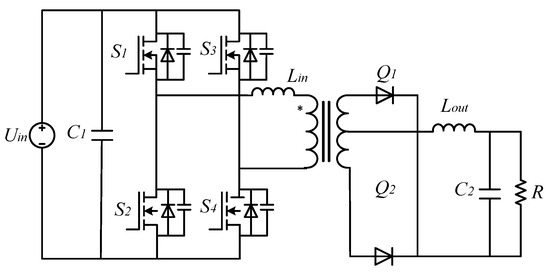
Figure 1.
Topological structure diagram of phase-shifted full bridge DC-DC converter.
The phase-shift control process of the converter is shown in Figure 2, where switches S1 and S2 are the leading leg, and S3 and S4 are the lagging leg. The conduction time interval between the leading leg and the lagging leg is the phase-shift angle, which determines the magnitude of the full-bridge output voltage. Ts represents the minimum period of a PWM switch, and the maximum duty cycle of the input-side leg is 0.5Ts.
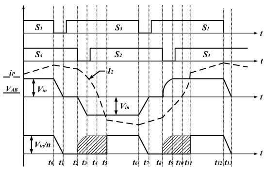
Figure 2.
Schematic diagram of drive logic.
2.2. Equivalent Mathematical Model
Analyzing the circuit principles of the phase-shifted full-bridge converter, the input side primary can be treated as an equivalent voltage source, and the operation process of the secondary side can be approximated as a Buck circuit. Under continuous current operation mode, the theoretical model of the converter satisfies the following relationship [24]:
In the formula, R represents the load, iL is the output current, and uc is the output voltage. Given a duty cycle of D, the relationship between the output voltage uc and the input voltage Uin is given by the following formula:
2.3. Control Framework Design
In the study of phase-shifted full-bridge converter, the control framework designed in this paper is shown in Figure 3, which is divided into four core modules: model predictive control design, disturbance observer design, duty cycle compensation, and phase-shifted control. Model predictive control design: As an inner loop control structure, the main function of this module is to make control decisions by predicting the future behavior of the system so as to improve the dynamic response ability of the system. Model predictive control can effectively deal with the nonlinear and time-varying characteristics of the system and achieve fast and accurate control. Disturbance observer design: In order to improve the robustness of the whole system, the disturbance observer is used to monitor the sudden change in parameters in the controlled system and random disturbance of the external environment in real time. The disturbance observer can adjust the control strategy in time by obtaining the system state information in real time, thus reducing the negative impact on the control system’s performance. Duty ratio compensation: During phase-shifting full bridge control, loss of duty ratio may lead to instability of output voltage. The duty cycle compensation module is specially designed to monitor and adjust the duty cycle to ensure that it remains at an ideal level during the operation of the converter to ensure the stability and reliability of the voltage output. Phase shift control: The main function of this module is to convert the equivalent duty cycle obtained by the model predictive control into the actual phase shift angle to achieve accurate control of the output voltage. By adjusting the phase angle reasonably, the phase shift control can effectively optimize the system performance and meet the requirements of voltage control. The control framework aims to improve the control performance based on a phase-shifting full-bridge converter through the synergy of various modules and achieve fast, accurate, and robust voltage control.
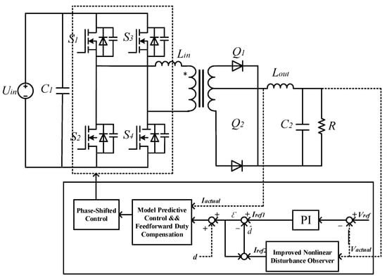
Figure 3.
Disturbance observer predictive current control block diagram.
3. PSFB Controller Design
3.1. Model Predictive Control Strategy
In this paper, the application of the model predictive control algorithm in the control process of a phase-shifted full-bridge converter is discussed. The implementation of the algorithm is mainly divided into three core steps: Firstly, the prediction model is constructed, and the corresponding mathematical expression is obtained by establishing the exact state-space equation to describe the working characteristics of the phase-shifted full-bridge converter. This step is critical to the effectiveness of the subsequent control strategy. Secondly, roll optimization control is the second key step. In this step, the algorithm continuously evaluates and optimizes the control strategy to achieve the optimal adjustment of the converter performance in each control cycle. This process involves the analysis of multiple scenarios that may arise in the system over a period of time in the future and the selection of the optimal control input. Finally, feedback correction ensures the stability and robustness of the control system. By comparing the actual output with the expected output, the system is adjusted in real time to reduce the error and improve the control precision. The specific implementation process is shown in Figure 4, which shows the specific operation and algorithm flow of each step in detail. Through the application of this series of steps, the application of the model predictive control algorithm in phase-shifted full-bridge converter control has been effectively verified, which not only improves the response speed and stability of the system but also provides new ideas and methods for practical engineering applications.
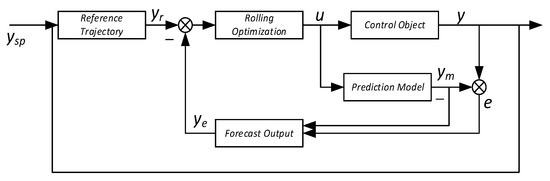
Figure 4.
Model predictive control flowchart.
First of all, the realization of a model predictive control strategy requires accurate modeling of the controlled system. The phase-shifted full-bridge converter is characterized by state space equation [25], and the following expression can be obtained:
Secondly, based on the first-order Euler formula, a discretized state space expression is established for the phase-shifting full bridge converter as follows [26]:
Finally, considering that model predictive control has an enhancing effect on the dynamic response capability of the system and can effectively achieve the controlled system to follow current changes, the current reference value is selected as the core consideration factor for the cost function. The expression for the cost function g is as follows:
3.2. Disturbance Observer Design
To suppress external random disturbances and sudden changes in controlled system parameters, this paper designs a nonlinear disturbance observer to observe them. The definition of random disturbances and parameter changes during the operation of a phase-shifting full bridge converter is lumped disturbance dtotal, and the expression of the converter model with added lumped disturbance is:
The disturbance observer observation value is defined as , and the disturbance estimation error satisfies the following equation:
It can be assumed that the variation of external random disturbances is very slow, and its derivative is estimated to be 0. Therefore, the differential of disturbance estimation error satisfies the following equation:
To ensure effective convergence of disturbance estimates, a convergence law can be designed to ensure that the error estimate tends towards 0. The perturbation estimation approach law is defined in the following form:
After substituting the above equation into the nonlinear system equation, a naive nonlinear disturbance observer can be obtained [27].
Due to the need for naive disturbance observers to utilize parameters, most systems typically cannot directly obtain the measured value. Therefore, based on the basic principle of improving the NDOB observer, an improved NDOB model can be obtained [28]:
In the formula, z is the intermediate variable, and p(x) satisfies the following relationship:
3.3. Duty Cycle Compensation and Phase Shift Control
Duty cycle loss refers to the difference between the effective duty cycle Dass of the secondary side and the duty cycle D of the primary side given by the driving signal, denoted as Dloss, which satisfies the following expression.
The problem of duty cycle loss is a major challenge in the control process of phase-shifting full bridge converters. The reason for this is that the voltage drop at both ends of the resonant inductor in the transformer’s primary side causes a decrease in the actual output voltage. Therefore, to solve this problem, based on consulting relevant literature [29], this article derives the calculation logic of the duty cycle Dloss and obtains the following relationship:
After algebraic simplification of the above equation, it can be concluded that
Phase shift control is the core step of the main phase-shifting full bridge converter studied in this article, and its phase-shifting angle modulation method satisfies the following equation:
4. Simulation Verification
To effectively verify the superiority of the proposed strategy, this paper builds a simulation of a 12.5 KW phase-shifting full bridge DC/DC converter, as shown in Figure 5, based on the Matlab-2022b/Simulink platform.
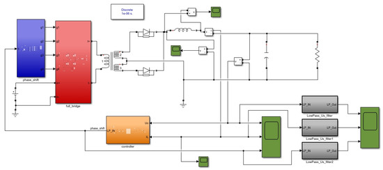
Figure 5.
12.5 KW phase-shifted full bridge converter simulation.
Among them, the main equipment parameters in the electrical system are shown in Table 1. Based on the same electrical equipment parameters, discuss the control effects of two control strategies separately.

Table 1.
Phase shift full bridge converter parameters.
4.1. Comparison Experiment of Traditional PI Control
To verify the proposed strategy’s ability to solve complex PI parameter tuning, this paper uses three sets of current loop PI parameter results to discuss the control effects of different parameters on the phase-shifting full bridge topology. As shown in Figure 6, the yellow curve represents the voltage response curve with a proportional parameter of 1 × 10⁻⁵ and an integral parameter of 5 × 10⁻²; the red curve represents the voltage response curve with a proportional parameter of 7 × 10⁻⁴ and an integral parameter of 1 × 10⁻⁴; and the blue curve represents the voltage response curve with a proportional parameter of 7 × 10⁻⁴ and an integral parameter of 5 × 10⁻². It can be seen that when different PI parameters are selected for the current loop, the response effect of the controlled system will be greatly affected. Moreover, when the PI parameters are not within a reasonable range, the system will not be able to respond correctly to the corresponding voltage.
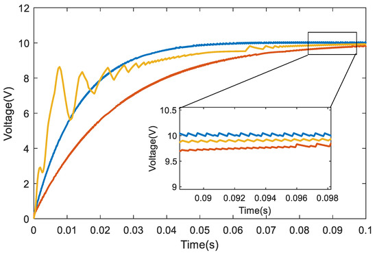
Figure 6.
Voltage response curve of different PI parameters.
However, when the model predictive control algorithm is applied to the current loop, the control effect of the system is shown in Figure 7, and its voltage control effect will no longer be affected by parameters, and the control effect will be excellent.
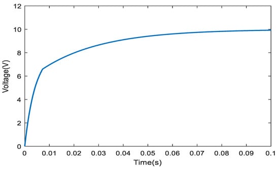
Figure 7.
Model predictive control voltage response curve.
Similarly, as shown in Figure 8, the above experiment has almost the same effect on current to ground as on voltage, where the dashed line represents the control effect of the model predictive control strategy.
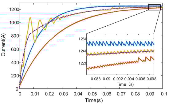
Figure 8.
Current response curve under PI control and model predictive control.
4.2. Load Mutation Experiment
To verify the response ability of traditional PI control strategy and MPC control strategy to resistance changes, a load sudden change experiment was designed. Drop the load suddenly from the initial 0.016 Ω to 0.008 Ω and observe the response-ability of the two control strategies. The results are shown in Figure 9, where the blue curve represents the current under the load sudden change condition under PI control, and the brown curve represents the current under the load sudden change condition under MPC control. Obviously, the current ripple of PI control is small, but the current response ability of MPC is faster.
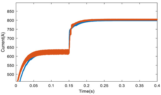
Figure 9.
Current response diagram under sudden load changes.
4.3. Inductance Parameter Mismatch Experiment
In order to verify the disturbance compensation capability of the observer in the case of mismatched inductance parameters of the system, we designed a comparative experiment. The experiment aims to compare the performance of the traditional predictive control strategy and the predictive control strategy with the improved disturbance observer in dealing with the mismatch of inductance parameters of the system. The experimental results are shown in Figure 10, where the blue curve and the brown curve, respectively, represent the current response of the two control strategies under the mismatch of output inductance parameters. Through comparative analysis, we find that although the predictive control strategy using improved nonlinear disturbance observer has a slight deficiency in response speed, it has a better effect on current pulsation suppression. Specifically, this strategy can effectively suppress the system disturbance caused by the parameter mismatch so as to ensure the stability and reliability of the system. This result shows that the improved predictive control strategy has a significant advantage in dealing with the problem of the mismatch of inductance parameters. In conclusion, through this experiment, we fully verify the application value of the improved disturbance observer in the predictive control strategy. In future studies, we hope to further optimize this strategy to improve its application effect in practical engineering.
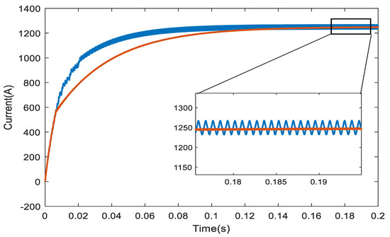
Figure 10.
Current response diagram of output inductance parameter mismatch under working conditions.
4.4. Current Random Disturbance Experiment
In order to verify the disturbance compensation capability of the observer under random current disturbance in the system, we carefully designed a series of comparative experiments. In the experiments, we set the value of current random disturbance, which is determined based on 5% of the rated output current, with the maximum disturbance value set at 60 A. The experimental results are shown in Figure 11. Through comparative analysis, we found that the controller using the traditional model predictive control strategy is prone to fluctuations in current response when faced with interference, which poses certain risks. However, under the predictive control strategy using the improved nonlinear disturbance observer, the controller is almost unaffected by interference and shows extremely high stability and reliability. This experimental result fully proves the superior performance of the improved nonlinear disturbance observer in system disturbance compensation, providing strong support for subsequent research.
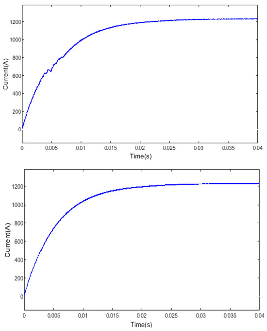
Figure 11.
Current response diagram of random current disturbance under working conditions.
5. Conclusions
In order to further improve the control effect of traditional electrolytic electroplating power supplies, based on an in-depth study of the phase-shifting full-bridge DC/DC converter topology structure, this paper proposes a brand new control strategy that combines model predictive control with disturbance observer technology. This innovative control strategy aims to enhance the dynamic response capability of the converter, strengthen the anti-interference performance of the system, and resolve the issue of duty cycle loss during the circulating process. Firstly, this paper employs the model predictive control (MPC) algorithm to design the inner control loop. The MPC algorithm can significantly improve the dynamic response capability of the converter by predicting the system state over a certain period of time and optimizing the control input based on this prediction. Through the design of the MPC algorithm, the converter can maintain good dynamic performance even when facing various complex load changes. Secondly, to enhance the anti-interference capability of the system, this paper utilizes an improved nonlinear disturbance observer. This observer can estimate the lumped disturbances affecting the system in real time, such as load disturbances and power supply disturbances. By estimating disturbances, the controller can adjust the control input in a timely manner to minimize the impact of disturbances on system performance. Finally, this paper designs a feedforward compensation section to address the issue of duty cycle loss during the circulating process. During the circulating process, the loss of the duty cycle can cause fluctuations in the converter’s output voltage. By designing the feedforward compensation section, this fluctuation can be effectively reduced, thereby improving the stability and reliability of the system. Simulation results show that, compared with the traditional PI control strategy, the proposed control strategy in this paper can effectively solve the inherent complex PI parameter adjustment problem of traditional control strategies. Moreover, compared with the traditional predictive control strategy, the system can better cope with various disturbances after the introduction of the improved nonlinear disturbance observer, which improves the robustness of the system. However, this paper also has certain limitations. Firstly, due to the absence of a hardware platform for experimental verification, the effectiveness of the proposed control strategy in practical applications still needs to be further verified. Secondly, this paper has not conducted more comparative experiments to discuss the designed control strategy’s effects on other types of DC/DC converters and whether it is also applicable to other potential application scenarios. These limitations will be addressed in subsequent research. In summary, the control strategy proposed in this paper based on the phase-shifting full-bridge DC/DC converter has significant advantages in theory. In future research, we will further conduct experimental verification and explore the potential applications of this control strategy in other fields. Through continuous improvement and optimization, we believe that this control strategy will provide a strong guarantee for the stable operation of electrolytic electroplating power supplies.
Author Contributions
Conceptualization, Y.W.; Methodology, Y.W., C.L., Q.Z. and L.L.; Software, Y.W., C.L., Q.Z. and L.L.; Validation, Y.W., C.L., Q.Z. and L.L.; Writing—original draft, Y.W., Qing Zhao and L.L.; Writing—review & editing, C.L. All authors have read and agreed to the published version of the manuscript.
Funding
This work was supported in part by the Jilin Province Development and Reform Commission Project 2022C045-11, by the Jilin Province Science and Technology Department project 20190101018JH.
Data Availability Statement
Data are contained within the article.
Conflicts of Interest
The authors declare no conflicts of interest.
References
- Gugua, E.C.; Ujah, C.O.; Asadu, C.O.; Von Kallon, D.V.; Ekwueme, B.N. Electroplating in the modern era, improvements and challenges: A review. Hybrid Adv. 2024, 7, 100286. [Google Scholar] [CrossRef]
- Nayanasiri, D.; Li, Y. Step-Down DC–DC Converters: An Overview and Outlook. Electronics 2022, 11, 1693. [Google Scholar] [CrossRef]
- Gao, Y.; Tang, Y.; Yao, F.; Ge, L.; Guo, Y.; Sun, H. Paralleled Variable Inductor Phase-Shifted Full-Bridge Converter with Full-Load Range ZVS and Low Duty Cycle Loss. IEEE Trans. Ind. Electron. 2024, 71, 4673–4684. [Google Scholar] [CrossRef]
- Yen, W.-W.; Chao, P.C.-P. A ZVS Phase-Shift Full-Bridge Converter With Input Current Steering to Reduce EMI Noise. IEEE Trans. Power Electron. 2022, 37, 11937–11950. [Google Scholar] [CrossRef]
- Xu, Z.; Pan, J. Research review of phase-shifted full-bridge ZVS DC converters. J. Power Sources 2022, 20, 11–27. [Google Scholar]
- Wang, P.; Xu, Z.; Wang, L.; Gao, L.; Wang, X. Hybrid Optimal Control Strategy for Efficiency and Dynamic Performance of dual active bridge DC-DC Converter based on triple Phase shift. Trans. China Electrotech. Soc. 2019, 37, 4720–4731. [Google Scholar]
- Wang, H.; Liu, Z.; Lv, J. Research on Model Predictive Control of Interleaved Parallel bidirectional DC-DC Converter. Guangxi Electr. Power 2022, 45, 49–54. [Google Scholar]
- Meng, L.; Hu, X. Dynamic compensation control of Buck bidirectional DC-DC Converter based on Model Predictive control. J. Power Sources 2024, 22, 90–97. [Google Scholar]
- Ullah, B.; Ullah, H.; Khalid, S. Direct Model Predictive Control of Noninverting Buck-boost DC-DC Converter. CES Trans. Electr. Mach. Syst. 2022, 6, 332–339. [Google Scholar] [CrossRef]
- Sadiq, M.; Aragon, C.A.; Terriche, Y.; Ali, S.W.; Su, C.-L.; Buzna, Ľ.; Elsisi, M.; Lee, C.-H. Continuous-Control-Set Model Predictive Control for Three-Level DC–DC Converter with Unbalanced Loads in Bipolar Electric Vehicle Charging Stations. Mathematics 2022, 10, 3444. [Google Scholar] [CrossRef]
- Razani, R.; Mohamed, Y.A.-R.I. Model Predictive Control of Non-Isolated DC/DC Modular Multilevel Converter Improving the Dynamic Response. IEEE Open J. Power Electron. 2022, 3, 303–316. [Google Scholar] [CrossRef]
- Dang, C.; Wang, F.; Mu, X.; Liu, D.; Tong, X.; Song, W.; Huang, J. Double vector predictive constant frequency control of Vienna Rectifier with inductance parameter identification. Proc. CSEE 2022, 42 (Suppl. S1), 246–255. [Google Scholar]
- Feng, X.; Cui, X.; Shao, K. A linear active disturbance rejection control strategy for Vienna Rectifier. Power Electron. Technol. 2020, 54, 103–105. [Google Scholar]
- Fu, X.; Wang, L.; Wang, X. Nonlinear sliding mode control strategy for grid-connected photovoltaic inverters. J. Shenyang Univ. Technol. 2022, 44, 694–699. [Google Scholar]
- Wang, R.; Li, J.; Sun, Q.; Zhang, H.; Wei, Z.; Wang, P. Energy Transfer Converter Between Electric Vehicles: DC–DC Converter Based on Virtual Power Model Predictive Control. IEEE Trans. Consum. Electron. 2023, 69, 556–567. [Google Scholar] [CrossRef]
- Tan, B.; Li, H.; Zhao, D.; Liang, Z.; Ma, R.; Huangfu, Y. Finite-control-set model predictive control of interleaved DC-DC boost converter Based on Kalman the observer. eTransportation 2022, 11, 100158. [Google Scholar] [CrossRef]
- Zhang, W.; Chen, L. Model Predictive Control Strategy for Three-phase Inverter Based on Disturbance Suppression. Electr. Drive 2019, 51, 43–50. [Google Scholar]
- Babayomi, O.O.; Zhang, Z.; Li, Z.; Park, K.-B. Bidirectional DC-DC converters for distributed energy resources: Robust predictive control with structurally-adaptive extended state observers. Int. J. Electr. Power Energy Syst. 2024, 158, 109913. [Google Scholar] [CrossRef]
- Chen, W.; Zeng, S.; Zhang, G.; Shi, T.; Xia, C. A modified double vectors model predictive torque control of permanent magnet synchronous motor. IEEE Trans. Power Electron. 2019, 34, 11419–11428. [Google Scholar] [CrossRef]
- Kang, S.; Soh, J.; Kim, R. Symmetrical three-vector-based model predictive control with deadbeat solution for IPMSM in rotating reference frame. IEEE Trans. Ind. Electron. 2020, 67, 159–168. [Google Scholar] [CrossRef]
- Li, X.; Peng, T.; Dan, H.; Zhang, G.; Tang, W.; Wheeler, P. A modulated model predictive control scheme for the brushless doubly fed induction machine. IEEE J. Emerg. Sel. Top. Power Electron. 2018, 6, 1681–1691. [Google Scholar] [CrossRef]
- Guo, L.; Jin, Y.; Cao, L.; Dai, L.; Luo, K. Hybrid single and double-voltage vector-based model predictive common-mode voltage reduction method for 2-level voltage source inverters. IET Power Electron. 2019, 12, 2086–2094. [Google Scholar] [CrossRef]
- Xu, H. Research on High-Reliability and High-Power Electroplating Power Supply. Master’s Thesis, Zhengzhou University, Zhengzhou, China, 2015. [Google Scholar]
- Capua, G.D.; Shirsavar, S.A.; Hallworth, M.A.; Femia, N. An enhanced model for small-signal analysis of the phase-shifted full-bridge converter. IEEE Trans. Power Electron. 2015, 30, 1567–1576. [Google Scholar] [CrossRef]
- Sun, T. Model Prediction of Direct Velocity Weak Field Control Strategy for Permanent Magnet Synchronous Motor Parameter Identification. Master’s Thesis, Xi’an University of Technology, Xi’an, China, 2023. [Google Scholar]
- Sun, X.; Zhou, Y.; Chen, G.; Ren, B. Model predictive control of a phase-shifted full-bridge dc-dc converter. In Proceedings of the 2020 IEEE 9th International Power Electronics and Motion Control Conference (IPEMC2020-ECCE Asia), Virtual, 29 November–2 December 2020; IEEE: New York, NY, USA; pp. 2710–2714. [Google Scholar]
- Liu, X.; Li, K.; Zhang, Q.; Zhang, C. Single-loop predictive control of PMSM based on nonlinear disturbance observers. Proc. CSEE 2018, 38, 2153–2162. [Google Scholar]
- Liu, Z.; Yuan, S.; Zheng, L.; Ma, Y.; Sun, Y. An improved NMPC-NDOB scheme for trajectory tracking of unmanned surface vessel. Proc. Inst. Mech. Eng. Part M J. Eng. Marit. Environ. 2022, 236, 1012–1024. [Google Scholar] [CrossRef]
- Cao, L.; Li, Y.; Li, X.; Guo, L.; Jin, N.; Cao, H. A Dual-Vector Modulated Model Predictive Control Method for Voltage Source Inverters with a New Duty Cycle Calculation Method. Energies 2020, 13, 4200. [Google Scholar] [CrossRef]
Disclaimer/Publisher’s Note: The statements, opinions and data contained in all publications are solely those of the individual author(s) and contributor(s) and not of MDPI and/or the editor(s). MDPI and/or the editor(s) disclaim responsibility for any injury to people or property resulting from any ideas, methods, instructions or products referred to in the content. |
© 2025 by the authors. Licensee MDPI, Basel, Switzerland. This article is an open access article distributed under the terms and conditions of the Creative Commons Attribution (CC BY) license (https://creativecommons.org/licenses/by/4.0/).