1. Introduction
The guiding opinions on China’s energy work point out that efforts should be made to promote the green and low-carbon transformation of energy, deepen energy reform and innovation, and improve the level of international energy cooperation. From the perspective of the power sector, the proportion of new-energy power generation will gradually increase. In different parts of the world, different countries and regions have different power grid modes. For example, in the North American single-phase power grid, there is a single-phase three-wire split-phase output power grid [
1,
2,
3,
4]. For L1/N/L2, the voltages between L1 and N and between L2 and N are both 120 V, with a phase difference of 180 degrees, and the voltage between L1 and L2 is 240 V. Therefore, a grid-connected inverter with a split-phase structure is required to match this power grid mode. As a bridge connecting renewable energy and the power grid [
5,
6,
7], the LCL filter in a grid-connected inverter is widely used due to its smaller volume and better high-frequency harmonic filtering ability [
8,
9]. However, the LCL-type filter has its own resonance issue. At its resonant frequency, there is a resonant peak with an infinite gain [
10,
11]. Simultaneously, the phase undergoes a 180° jump and crosses ±180°. If this resonant peak is not damped, it may render the grid-connected inverter unstable [
12,
13,
14,
15]. Consequently, damping the resonant peak of the LCL-type grid-connected inverter to ensure its stable operation under various operating conditions is of great significance [
16,
17].
There are two main types of resonance peak damping methods for an LCL-type filter, namely passive damping and active damping [
18,
19,
20]. Passive damping involves connecting a resistor in series or in parallel with the inductor or capacitor branch of the filter circuit. The authors of [
21] presented an improved passive damping method of connecting a resistor in parallel with the capacitor, which can significantly reduce the loss in the damping resistor. However, loss in the damping circuit is still difficult to avoid, and it increases the volume of the filter and reduces the overall system efficiency. In view of this, scholars have proposed active damping, which uses a control algorithm to simulate a damping effect similar to that of passive damping, thus avoiding losses. The authors of [
22] showed that after an equivalent transformation of the block diagram of an LCL grid-connected inverter system, it can be proven that the capacitor current feedback is equivalent to a virtual impedance connected in parallel with the filter capacitor C, and the resistance part in the virtual impedance plays a damping role. However, due to the control delay in digital control, this virtual resistance changes with the frequency, posing a great challenge in practical applications. The grid-connected control of the inverter includes inverter-side current control and grid-connected-side current control. Using inverter-side current control has an inherent damping effect [
23]. When the LCL resonant frequency is lower than one-sixth of the sampling frequency, that is,
, the system can be stabilized [
24]. However, when
, it is difficult to stabilize the system, and in this case, active damping of the capacitive current is still required. For capacitor-current active-damping inverter-side current control, that is, dual-feedback inverter-side current control, although there are descriptions of its stability improvement [
25,
26], its operating conditions have not been fully demonstrated. The robust damping gain depends on the inverter-side inductor and the filter capacitor, and the stability of its fluctuations is still unclear.
Based on the above analysis, this paper presents a more in-depth study of the grid-connection strategy of the LCL-type grid-connected inverter. Moreover, verification was carried out on a 12 kW experimental prototype. The main contributions are as follows.
- (1)
In a discrete-time system considering a 1.5-sample-period control delay, a comprehensive analysis of the system stability with respect to power grid impedance variations was carried out.
- (2)
A composite active damping strategy is proposed. Different from other methods that obtain the range of the capacitor current feedback coefficient using constraint conditions, this strategy can simply and standardly calculate the specific value of the capacitor current feedback coefficient. Meanwhile, it has good robustness.
- (3)
To enhance the system’s anti-interference ability against power grid harmonics, a brief analysis was conducted on the mechanism of how power grid harmonics affect the grid-connected current waveform. Finally, a commonly used MPR controller was selected and incorporated [
27]. When harmonics exist in the power grid, the MPR controller effectively improves the waveform and reduces the THD of the grid-connected current.
The structure of this article is as follows.
Section 2 expounds on the circuit structure and mathematical model of the split-phase three-level LCL grid-connected inverter.
Section 3 proposes a highly robust hybrid active-damping grid-connection strategy.
Section 4 validates the proposed method through experiments.
Section 5 summarizes the work.
2. Main Circuit Principle and Mathematical Model
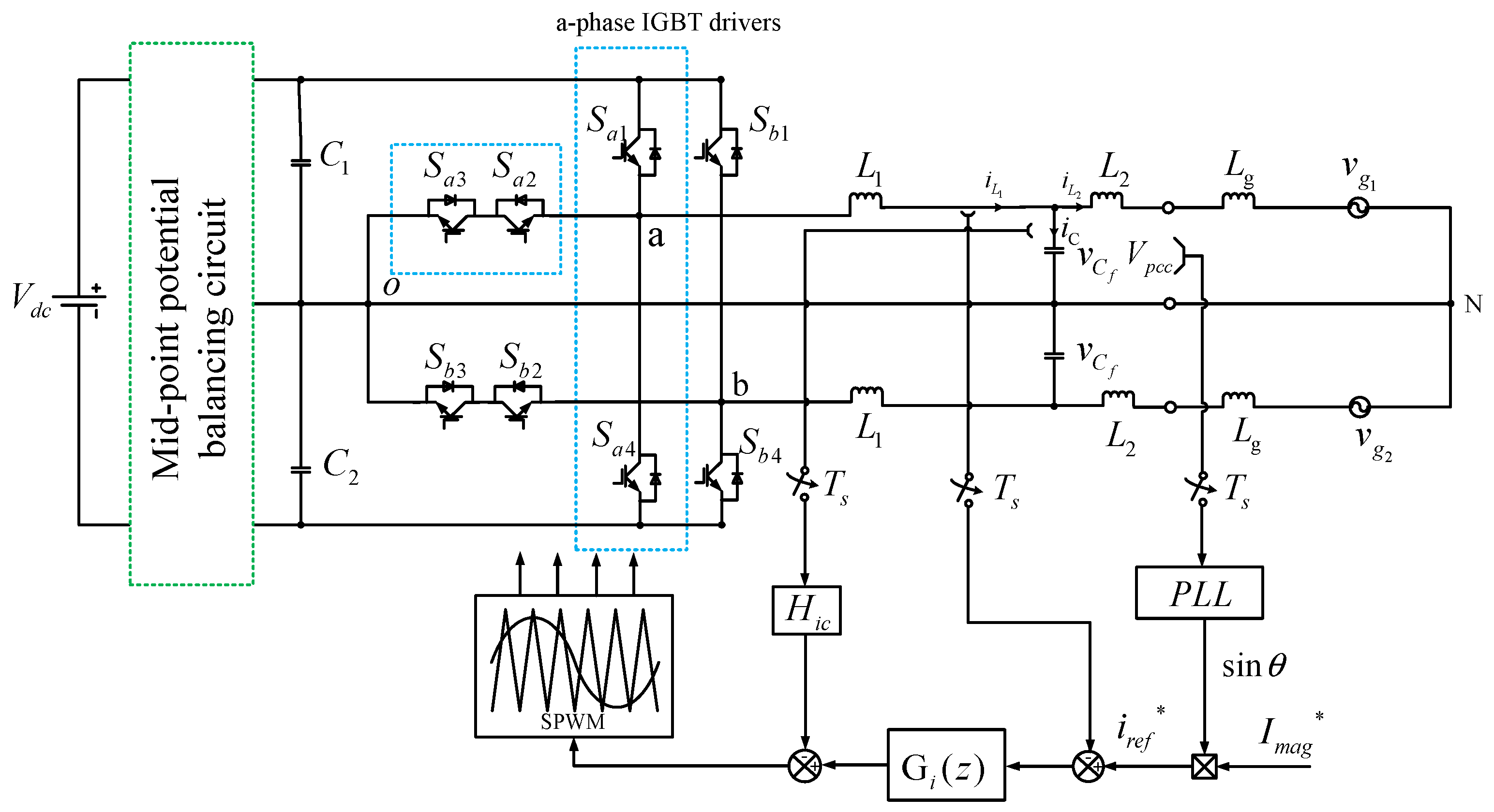
A structural diagram of the split-phase T-type three-level LCL-type grid-connected inverter system is shown in
Figure 1. In view of the mid-point offset phenomenon existing in the three-level circuit, this study used a hardware circuit for control. The inverter circuit consists of two-way T-type three-level structures
,
,
, and
(
). The inverter-side inductor
, the grid-side inductor
, and the filter capacitor
form an LCL filter.
is the voltage at the point of common coupling;
is the equivalent grid impedance; and
and
are split-phase grid voltages with a phase difference of 180°.
is the sampling period. Since the two phases of the split-phase system can be controlled independently, phase a is selected for analysis. The system utilizes the inductor current on the inverter side for feedback. In the control process, the voltage at the PCC (point of common coupling) is first to be sampled for phase-locking. The given magnitude of the grid-connected current is
, which is multiplied by the sinusoidal signal output from the phase-locked loop (PLL) to obtain the current command
. After comparing the command with the sampled inductor current, the resulting current error is fed into the current regulator
for set-point tracking. To suppress the resonance peak of the LCL filter, proportional feedback of the capacitor current is adopted for active damping, with the feedback coefficient being
. Finally, the obtained modulation wave is modulated using SPWM (sinusoidal pulse-width modulation) to output the driving signal for the switching devices. The magnitude of the triangular carrier wave of the DSP (digital signal processor) is denoted by
.
By writing differential equations for the object part according to Kirchhoff’s laws and performing Laplace transforms, the mathematical model of the system can be obtained as follows:
The digital modulator incorporates both computational and PWM delays. The computational delay, equivalent to one sampling interval, is represented by the model
. Meanwhile, the PWM delay, amounting to half a sampling period, arises from the zero-order hold (ZOH) and is described as:
According to References [
24,
26], the active damping control block diagram in
Figure 2 is proposed.
Figure 2 shows the equivalent s-domain control block diagram of the a-phase grid-connected inverter considering the 1.5-sample-period control delay introduced by digital control. Here,
represents the pulse-width modulation gain, and numerically, it is expressed as
.
is a quasi-PR (QPR) controller, and its transfer function is:
In Equation (3), is the proportional coefficient, is the fundamental-frequency resonance coefficient, is the fundamental-wave angular frequency, and is the cut-off frequency of the QPR controller.
3. Grid-Connection Control Strategy
3.1. Analysis of Grid-Connection Stability
When the grid impedance
changes, the resonance frequency of the grid-connected inverter system changes accordingly. This causes the resonance peak frequency introduced by the filter to vary within a wide range. It is necessary to design a reasonable capacitor current feedback coefficient to effectively dampen the resonance peak during this change process. A stability analysis of the control block diagram is conducted, as shown in
Figure 2. Since the grid voltage does not affect the denominator of the transfer function, it can be ignored during the stability analysis. The open-loop transfer function expression from
to
in the s-domain can be obtained as follows:
By discretizing the open-loop transfer function using the ZOH, the expression of the open-loop transfer function in the z-domain can be obtained as follows:
In the formula, .
It can be seen in Equation (5) that there is a pair of complex zeros in the system, which will result in a negative resonance peak in the Bode plot. The resonance frequency at this point is denoted by
:
According to the Nyquist stability criterion, the necessary and sufficient condition for the system to remain stable is:
In this equation, represents the number of closed-loop poles of the system in the right-hand plane; represents the number of open-loop poles of the system in the right-hand plane; represents the number of effective positive-crossing times in the Bode plot; and represents the number of effective negative-crossing times in the Bode plot.
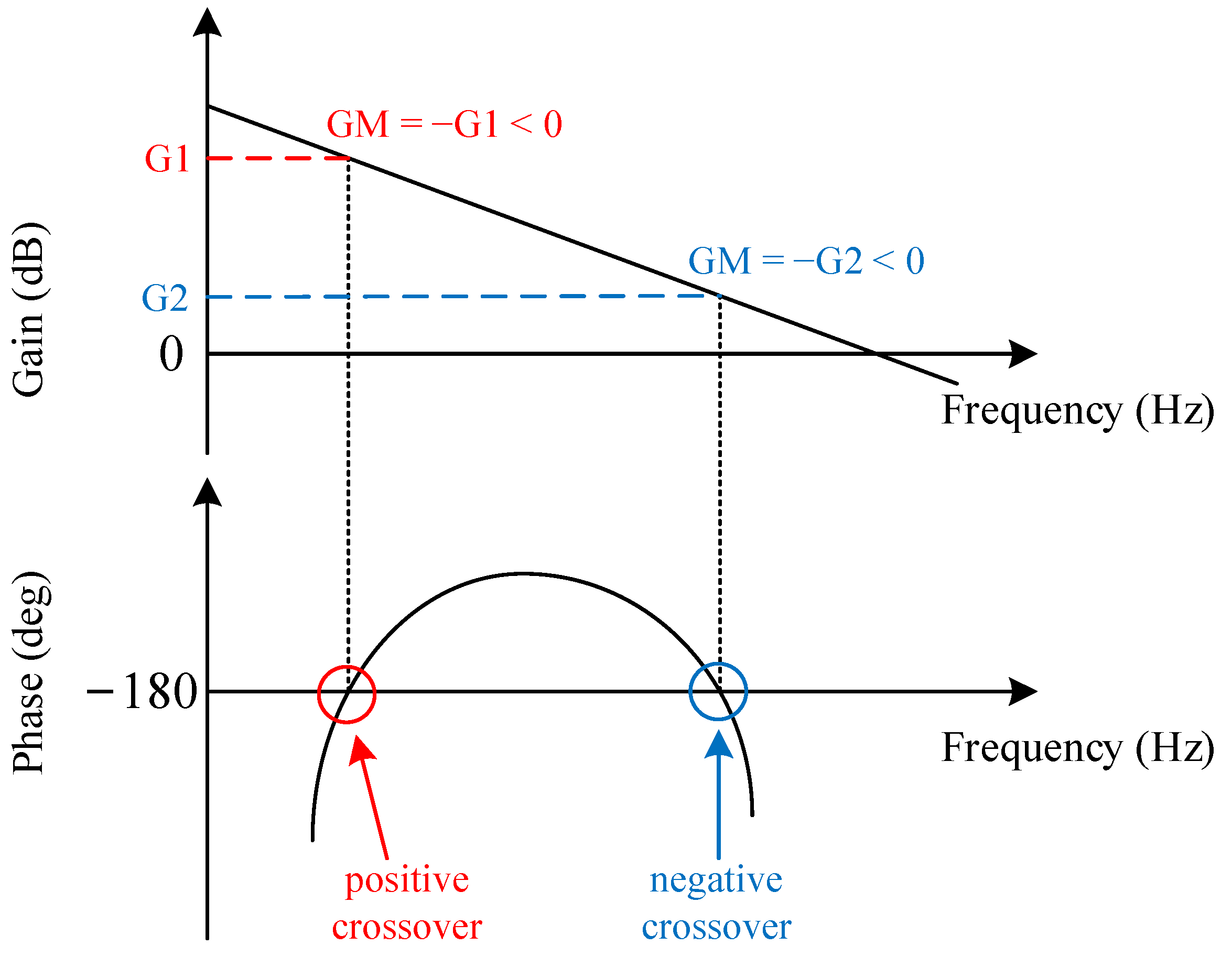
In a Bode plot, if the phase-frequency curve intersects the line of −180° × (2
n + 1) (where
n is an integer) from below upward, and the value of the gain-frequency curve at the intersection point is greater than 0 dB, a positive crossover is defined to occur. When the phase-frequency curve intersects the line of −180° × (2
n + 1) (where
n is an integer) from above downward, and the value of the gain-frequency curve at the intersection point is greater than 0 dB, a negative crossover is defined to occur. The distance from the gain-frequency curve at the intersection point up to 0 dB is defined as the gain margin, denoted as GM. This means that when the crossover is an effective one, GM < 0. A schematic diagram of a positive and negative crossover and the corresponding GM are shown in
Figure 3 below.
As can be seen in Equation (5), the value of the number
of open-loop poles of the system in the right-hand plane is determined using Equation (8):
is substituted to map equation (8) into the
w-domain, and the result is:
Based on the four coefficients in Equation (10), a Routh table is formulated. The elements in the first column are , , , and , respectively. Considering that the capacitor current feedback coefficient is , and always hold.
The constraint conditions for
and
to be greater than 0 are:
undergoes a sign change at , undergoes a sign change at , and the relative magnitudes of and change at .
When the current regulator is not considered (
), the values of
and
under different circumstances are studied. Both the positive and negative crossings of the phase–frequency curve may occur at
and
. The subscripts (+) and (-) are used to denote positive and negative crossing conditions at frequencies.
is defined as the gain margin at
, and
is defined as the gain margin at
. As the magnitude of the grid impedance
changes, the resonant frequency
will also be in different intervals. The three intervals through which
changes are defined as operating states 1, 2, and 3, as shown in
Table 1. According to the Nyquist stability criterion, the following table lists the gain margin requirements for the system to be conditionally stable under different intervals of
and
.
3.2. Robust Capacitor Current Feedback Coefficient and Lead Correction
The cut-off frequency of the current regulator
is much lower than the resonant frequency range of the inverter system. Therefore, in the following calculation and analysis, it can be simplified to a pure proportional link
. When
and
are substituted into Equation (5), the expressions of
and
, respectively, can be obtained:
As indicated by the stability requirements in
Table 1, the requirement for
changes sign in operating states 1 and 2. In addition, according to Equations (12) and (13), at
,
always holds. As shown in
Figure 4a, if
, the stability requirements cannot be met near the intersection region of operating states 1 and 2. Only when
is the unstable region minimized, as shown in
Figure 4b.
The critical grid inductance value
can be obtained from
, and the capacitor current feedback coefficient
with high robustness can be obtained from Equation (12) and
:
When
takes the value of
, the stability conditions of the three operating states can all be satisfied. However, when
is
, in the Bode plot, the phase–frequency curve is tangent to
, as shown by the dotted line in
Figure 5. This means that the system is in a critically stable state and is relatively sensitive to changes in circuit parameters. Therefore, to ensure that the system remains stable across the full range, a method is needed to adjust the phase–frequency curve at the critically stable point.
As can be seen in
Table 1, when
, the number of open-loop poles of the system is
. For the system to be stable, according to the Nyquist stability criterion, in this case, one effective positive crossing and one ineffective negative crossing are required, that is,
and
. Embedding a lead-phase correction in the current regulator can exactly meet the requirements of the stability conditions. The Bode plot after adding the lead correction is shown as the solid-line part of
Figure 5. To reduce the phase error at a specific frequency after discretization, the bilinear transformation with frequency pre-distortion is adopted for the lead correction. The transfer function of the lead correction is defined as
, and its expression in the
z-domain is:
In this equation, both α and τ are parameters of the lead correction; .
3.3. Grid Harmonic Disturbance Suppression
By performing block-diagram transformation on the control block diagram of the active damping system in
Figure 2, the following control block diagram can be obtained.
After further simplifying the control block diagram in
Figure 6, the open-loop transfer function
from the current command to the grid-connected current can be obtained.
The expression of the grid-connected current
is:
The expression of
is:
The power grid usually contains low-frequency odd-order harmonics, such as the third, fifth, seventh, and ninth harmonics. The multiple-frequency harmonics can cause voltage waveform distortion in the power grid, which further affects the grid-connected current waveform of the grid-connected inverter. According to Equation (18), it can be seen that the grid-connected current consists of two parts: the current command and the power–grid–voltage disturbance. For the second part of the power–grid–voltage disturbance, two methods are generally available to suppress the background harmonics of the power grid.
Grid-voltage feedforward is adopted to cancel out the second part of Equation (18). In this way, the interference of grid background harmonics can be eliminated. However, since the commonly sampled grid voltage is the voltage at the PCC, when there is a significant difference between the grid voltage and the voltage at the PCC, there is an even higher requirement for the accuracy of the model.
A PR controller is used in parallel with a multiple-resonance controller. When the open-loop gain of the controller for the frequency-multiplied harmonics is large enough, the gain of the grid disturbance in the second part of Equation (18) is very small. As a result, the influence of these disturbances on the tracking of the grid-connected current is so small that it can even be neglected.
To sum up, for the problem of suppressing the background harmonics of the power grid, the current regulator is changed from a PR controller to an MPR controller.
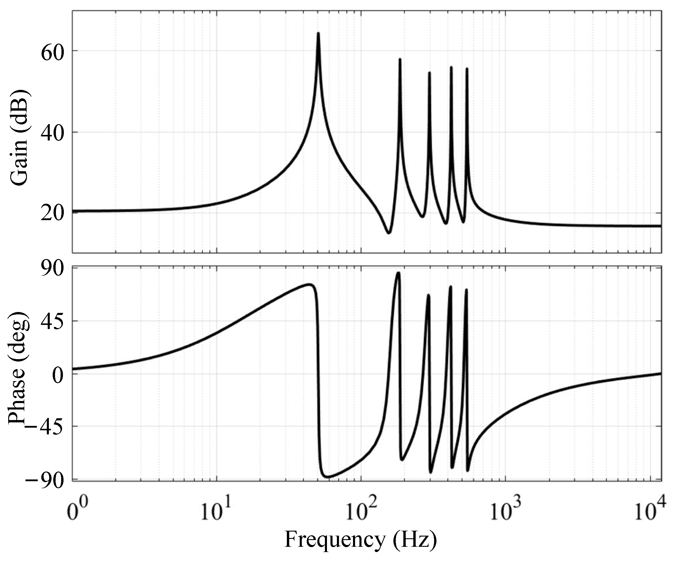
Figure 7 illustrates the open-loop Bode diagram of the MPR controller. The transfer function expression of MPR is as follows:
In the equation, h is the multiple of the fundamental frequency that needs to be suppressed.
4. Experimental Verification
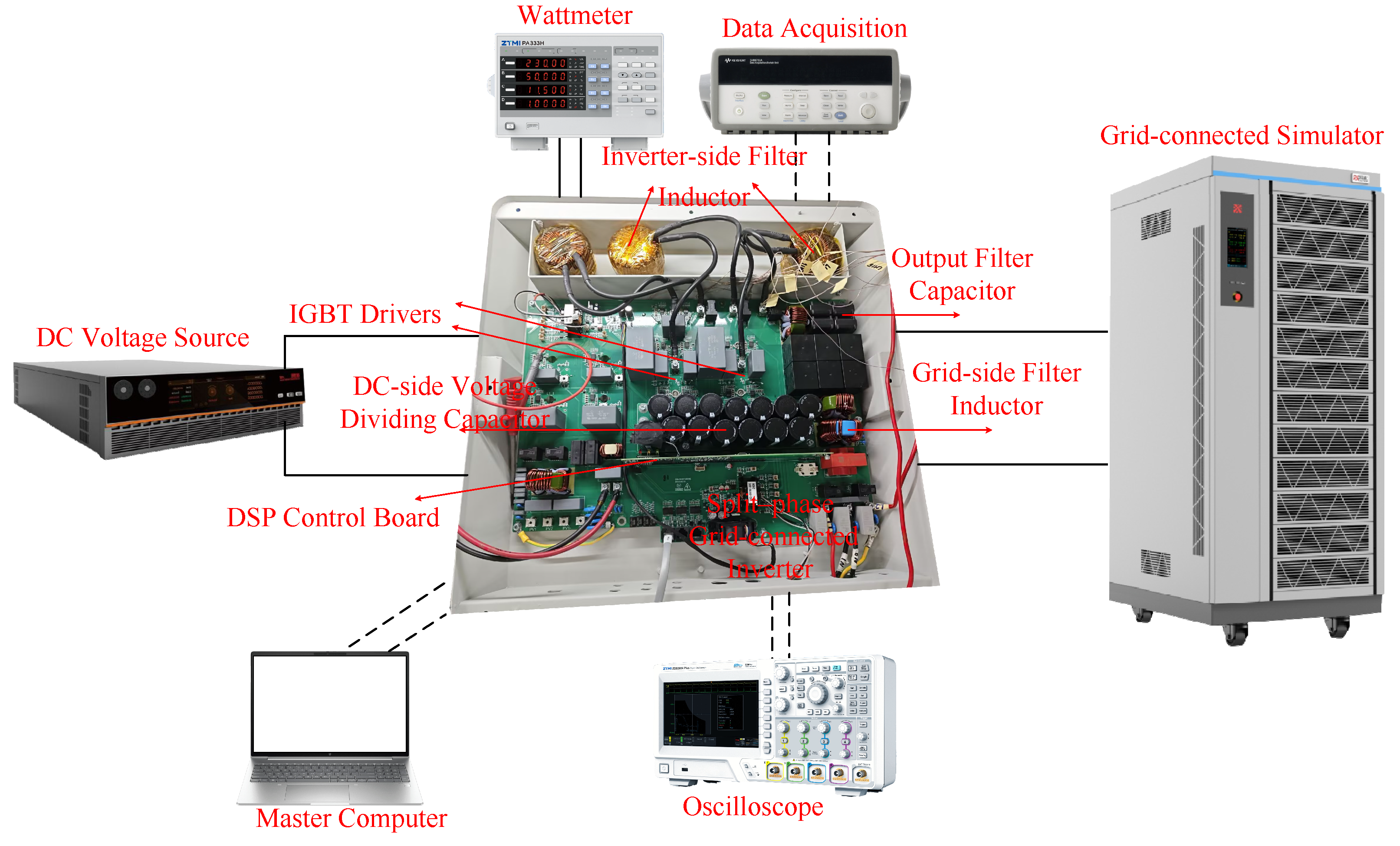
To verify the effectiveness of the proposed grid-connected control strategy, an experimental platform for the split-phase T-type three-level grid-connected inverter was built. The experimental platform is shown in
Figure 8. It consists of a bi-directional DC source and a bi-directional AC source, which serve as the DC-side input and the grid-connected simulator, respectively. Variable impedance on the grid side can be achieved by setting the internal resistance of the AC source. The bi-directional AC source can operate in single-phase, split-phase, and three-phase modes. By adopting the split-phase mode, a single-phase three-wire split-phase power grid can be simulated.
The parameters involved in the experiment and the control strategy are shown in
Table 2.
The experimental verification is mainly divided into two parts. The first part is the verification of the effectiveness of the composite active damping control strategy. The second part is the verification of the effectiveness of the harmonic suppression control of the MPR controller for grid background harmonics.
Figure 9 shows the full-load waveforms when the grid impedance takes values of
and
3.2 mH, respectively. The effective value of the current command is the rated current of 50 A. Due to the limitation of the number of oscilloscope channels, phases a and b are controlled independently. Therefore, in
Figure 9a, the grid-connected waveform of phase a is presented.
Figure 9a is divided into two parts: ① and ②. The scale ratio of the y-axis is marked on the left, and the reference value of the y-axis is marked on the right. In the figure,
represents the positive bus voltage,
represents the negative bus voltage,
is the grid voltage of phase a,
is the grid-connected current of phase a,
is the grid voltage of phase b, and
is the grid-connected current of phase b. According to the AC instantaneous power of the inverter, its instantaneous power contains a double-frequency component and a DC component. According to the law of conservation of energy, the instantaneous power on the DC side will also contain a double-frequency component. When the hardware mid-point balance control is adopted, as can be seen in
Figure 9a, during the double-frequency fluctuation of the DC-side voltage,
, and the mid-point potential offset does not exceed
. This experimental result shows that the hardware balance circuit adopted in this study can achieve the effect of mid-point balance.
By adopting the composite active damping strategy proposed above, it can be seen in
Figure 9a,b that the grid-connected current waveforms of the two phases are stable, with an effective value of approximately 50 A, and they are in the same phase as the voltage at the PCC point.
In
Figure 10, the grid impedance is set to
. At the positive zero-crossing point of phase a during the stable operation stage, the lead-phase correction is removed. At this time, the grid-connected current starts to oscillate. After 12 ms, the lead-phase correction is added again, and then the grid-connected current begins to converge and tends to be stable. The above experimental results show that during a wide-range change in the grid impedance, the proposed composite active damping strategy can achieve stable operation.
To demonstrate the superiority of the proposed method, an ICFAD strategy from Paper [
28] and the composite active damping strategy proposed in this paper were respectively applied on the experimental platform. When
, the experimental waveform of the composite active damping control strategy is shown in
Figure 11a, and the experimental waveform of the ICFAD strategy is shown in
Figure 11b. In
Figure 11a, the grid-connected current is stable and has good waveform quality. In
Figure 11b, although the grid-connected current does not diverge, there is a relatively obvious oscillation. The experimental results indicate that the composite active damping strategy proposed in this paper has better robustness under the variation of grid impedance.
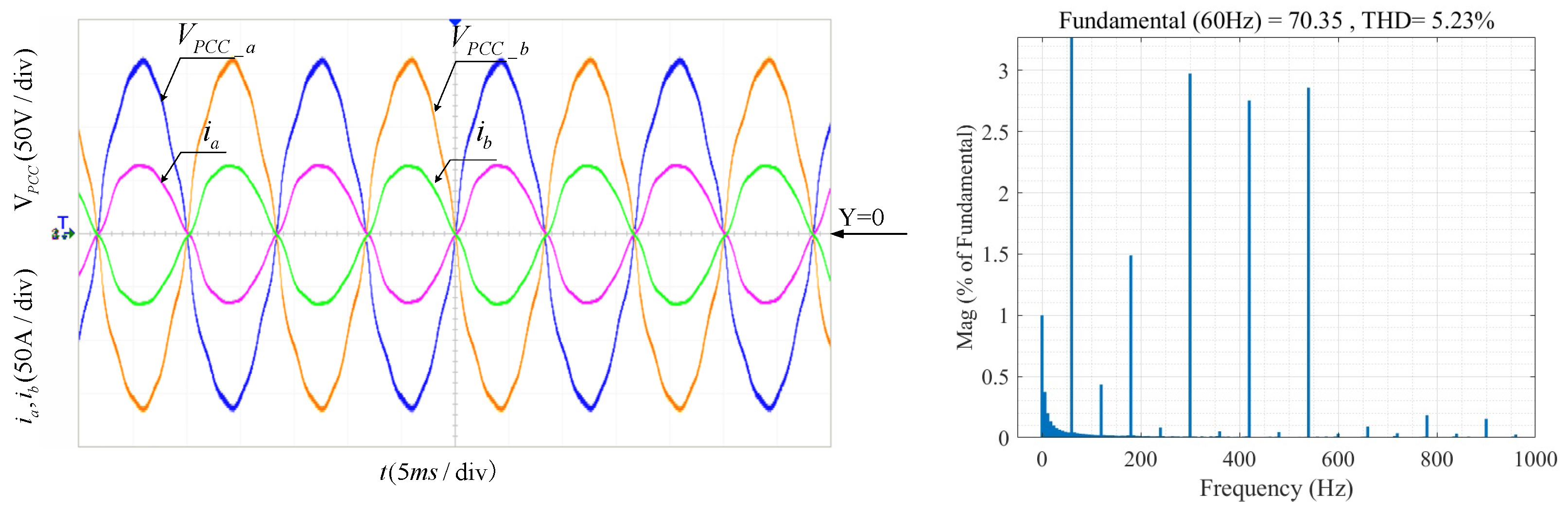
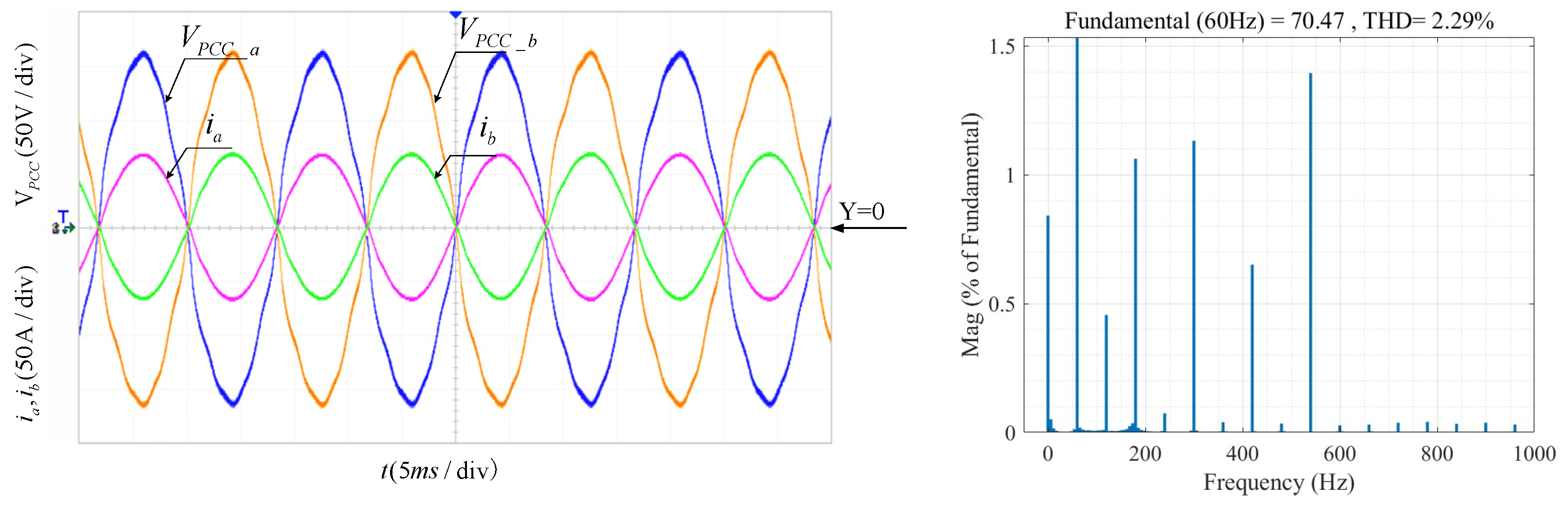
To verify the suppression effect of the MPR controller on power grid background harmonics, 3% of the third, fifth, seventh, and ninth harmonics was added to each of the two phases of the grid simulator. In
Figure 12, when only the PR controller is used, the grid-connected waveform is distorted, and the total harmonic distortion (THD) of the grid-connected current is 5.23%.
In
Figure 13, when the MPR controller is used, the grid-connected waveform is significantly improved, and the THD is reduced to 2.29%.
The experimental results show that the MPR controller can effectively suppress the background harmonics of specific frequencies in the grid.
5. Conclusions
This paper focuses on the research of the grid-connection control strategy for the split-phase T-type three-level LCL grid-connected inverter. First, the stability of the inductor-current feedback system on the inverter side, considering the variable impedance of the power grid, is analyzed. Three different operating states and stability requirements during the variation of the grid impedance are summarized. Based on this, an optimized method for calculating the capacitor current feedback coefficient for active damping is proposed to maximize the stable operating range of the system. Compared with traditional methods of calculating the capacitor current feedback coefficient, this approach is more straightforward and standardized, enabling the calculation of specific values. For the critical unstable state, this study further presents a composite active damping strategy with the addition of leading-phase correction to improve system stability. Additionally, to deal with the distortion of the grid-connected current caused by grid background harmonics, an MPR controller is adopted, effectively reducing the THD of the grid-connected current. Finally, the effectiveness of the proposed control strategy is demonstrated through a 12 kW experimental prototype. The experimental results show that, compared with the ICFAD method, the composite active damping strategy proposed in this paper exhibits stronger robustness and can achieve stable operation over a wide range of grid-impedance variations. The incorporated MPR controller significantly enhances the anti-interference ability of the grid-connected inverter against power grid harmonics. When low-order harmonics exist in the power grid, after changing from a PR controller to an MPR controller, the THD of the grid-connected current decreases from 5.23% to 2.29%. However, this paper still has some limitations. When the digital control delay is higher than 1.5 sample periods, or when the grid impedance changes from inductive to resistive-inductive or even capacitive, further in-depth research is required.


