Abstract
An improved super-twisting sliding mode and linear active disturbance rejection control strategy is proposed to improve the dynamic response performance and immunity performance in switched reluctance motor speed control systems. Firstly, the linear extended state observer in linear active disturbance rejection control is improved by using the super-twisting sliding mode (STSM) control algorithm in order to improve the performance of the observer and thus enhance the controller’s immunity to disturbances. Secondly, the STSM control algorithm is used to replace the original linear state error feedback control law to improve the dynamic response performance of the controller, and the sigmoid function is used to replace the sign function in the STSM algorithm to further weaken the inherent chattering of the sliding mode and improve the stability of the system. Finally, the proposed control strategy is verified using the MATLAB/Simulink simulation platform. The simulation results show that the proposed control strategy has a better dynamic response and disturbance immunity performance.
1. Introduction
Currently, new energy vehicles are developing at a rapid pace. The performance of the motor, an important component in the electric system, is assessed using key measures such as its usage efficiency, cost, and output power [1]. Switched reluctance motors (SRMs) have many advantages, such as a wide speed range, high reliability, and easy control, which make them highly competitive in the field of electric vehicles [2,3]. However, due to the influence of the unique double convex pole structure of SRMs, which leads to the nonlinearity and strong coupling of the magnetic circuit of SRMs, developing an ideal mathematical model presents significant challenges. Additionally, there is large torque pulsation in practical applications, which limits the promotion of SRMs in the field of high precision [4,5,6].
With the advancement of control theory, various strategies have been implemented in SRM control systems. The predominant approaches for speed control of SRMs include proportional integral (PI) control [7], fuzzy logic control, sliding mode control (SMC), and active disturbance rejection control (ADRC), among others. PI control is easy to operate and can be applied to different control objects, but it cannot completely eliminate the steady-state error of the controlled object and may lead to an overshooting phenomenon of the controlled object [8]. Fuzzy control achieves system control based on fuzzy logic rules without requiring precise mathematical models, but the establishment of the rule base relies on experience and an extensive dataset from experiments [9], so it is subjective and difficult to achieve high-precision control. Sliding mode control drives the system’s state to converge to the sliding mode surface by designing the sliding mode surface and the convergence law [10], but the system will generate high-frequency vibration near the sliding mode surface. ADRC actively estimates and compensates for both internal and external disturbances in real time, collectively referred to as the ’total disturbance’ [11], which does not depend on the exact model. However, it involves complicated parameter tuning and high computational demands, which can negatively affect real-time control performance.
Previous research [12] has designed the sliding mode convergence law by introducing system state variables, effectively reducing the steady-state error. SMC uses discontinuous control laws, such as the sign function, to drive the system state toward the sliding mode surface. However, this discontinuity causes the control input to undergo abrupt switching when the state is near the sliding mode surface, resulting in high-frequency oscillations. As the system approaches the sliding mode surface, frequent state transitions occur, leading to continuous fluctuations in the control input, which in turn induce high-frequency oscillations, manifesting as chattering [13]. The literature [14] contrasts traditional sliding mode control with super-twisting sliding mode (STSM) control. Traditional STSM improves control performance and reduces chattering by introducing a super-twisting structure. However, the use of the sign function still presents significant limitations. The non-smooth nature of the sign function and its high-frequency switching are the fundamental causes of chattering. Previous studies [15,16] have utilized the non-singular fast terminal sliding mode control for controller design, improving the system’s response speed and ensuring that the tracking error converges within an effective time. However, the algorithm’s complexity demands high controller accuracy, which may cause system instability under external disturbances. Another study [17] presented linear active disturbance rejection control (LADRC), which simplifies ADRC by utilizing the linear extended state observer (LESO) and linear state error feedback (LSEF) control laws, ultimately reducing the number of adjustable parameters. However, conventional LADRC struggles to balance dynamic response performance and system immunity, and when the input–output relationship of a nonlinear system is complex and irregular, its linear controller may fail to effectively capture and compensate for these nonlinear characteristics, resulting in a degradation in performance. One study [18] proposed a new sliding mode convergence law that substitutes the sign function with a smoothing function to minimize system jitter. It also designs an active disturbance rejection extended state observer and uses the observed value as feedforward compensation for the sliding mode speed controller, reducing the impact of the motor’s inherent parameter uncertainties on the control system. Research in [19] showed an improvement in the system’s dynamic response performance by introducing global fast terminal sliding mode control and a load torque observer. However, fast terminal sliding mode control can lead to singularity issues.
Sliding mode control features rapid response speed and strong robustness, making the combination of sliding mode control and LADRC effective for improving system performance. Among them, super-twisting sliding mode control is widely used because it does not require introducing new control variables, provides continuous output, and significantly reduces jitter [20,21,22]. In the literature [23], the discrete-time super-twisting sliding mode current controller is employed to ensure robustness and a fixed switching frequency, while eliminating the need for knowledge of the motor’s parameters during implementation. This results in a simple and adaptable control structure. However, the controller requires precise gain selection, as different gain ranges can lead to variations in steady-state time and ripple values. Improper selection of gains may degrade the performance of the system. One study [24] displayed enhancement of the linear active disturbance rejection speed controller by incorporating the STSM algorithm. However, the introduction of sliding mode control in the design process increases the observation burden on the linear extended state observer due to its inherent jitter. The torque sharing function (TSF) approach is a strategy used for torque control in SRMs. The TSF uses a designed optimal torque sharing function to generate the torque reference value for each phase, and then a torque hysteresis comparator is used to control phase switching [25,26].
This paper focuses on the SRM control system, integrating the STSM algorithm with LADRC in the velocity loop to enhance system performance and disturbance rejection. A novel strategy combining the improved super-twisting sliding mode and linear active disturbance rejection control (ISTSM-LADRC) is presented. This control strategy uses the STSM algorithm to improve the LESO in LADRC. The error signal in the LESO is tracked by the STSM algorithm, enabling the error signal to quickly converge to zero, which optimizes the tracking performance of the LESO and further enhances the disturbance rejection capability of the entire system. In addition, the STSM algorithm is utilized to enhance the original LSEF control law, thereby improving the dynamic response performance of the SRM control system. Meanwhile, to reduce the inherent chattering of sliding mode control, the sign function in the STSM algorithm is replaced with a sigmoid function, which reduces the observation burden on the LESO and effectively improves system stability. The ISTSM-LADRC control strategy can reduce settling time and effectively suppress torque ripple more effectively than the STSM and PI control strategies.
The structure of the paper is as follows: Section 2 presents the mathematical model of the switched reluctance motor (SRM), including the system’s equations and dynamics. Section 3 discusses the design of the conventional LADRC speed controller. In Section 4, the proposed ISTSM-LADRC strategy is introduced, including its design and implementation details. Section 5 provides the simulation results and compares the performance of the proposed control strategy with traditional methods. Finally, Section 6 concludes the paper by summarizing the key findings and contributions.
2. Mathematical Model of the SRM
The drive system of the SRM consists of several key components, including the power converter, the SRM itself, the controller, the control circuitry, and the voltage and current detection circuits in the feedback system. Figure 1 illustrates the asymmetric half-bridge topology of the SRM power converter. A, B, and C represent the three phases of SRM.
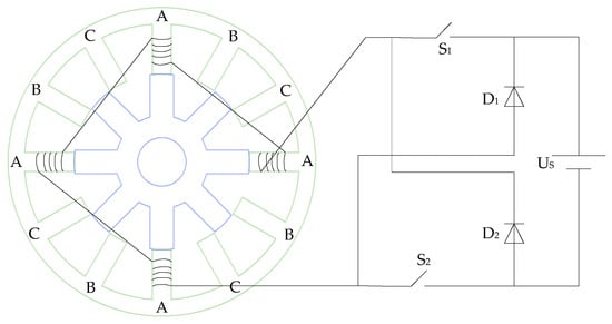
Figure 1.
Operating principle diagram of a three-phase 12/8 pole switched reluctance motor (SRM) (only one phase shown).
The existence of phase-to-phase coupling and the high nonlinearity of the system in the SRM make its accurate mathematical modeling more difficult. To reflect the complex electromagnetic relationships in the SRM, consider one phase as an example. The voltage balance equation in the stationary reference frame of the SRM is as follows:
where is the phase current, is the resistance value of each phase winding, and is the phase magnetic flux.
The inductive expression for the phase of the SRM is as follows:
The inductance can be expressed in terms of the rotor position angle and the phase current .
According to the principle of imaginary displacement, the instantaneous torque equation of the SRM at any operating point can be expressed as follows:
where is the torque and is the magnetic common energy of the winding.
As the air gap of an SRM changes with rotor position, the motor’s inductance, rotor position, and current present a binary nonlinear function. To accurately describe the motor’s characteristics, various methods can be used to obtain information about the actual motor’s inductance. For example, one can use finite element simulation by inputting the motor’s design parameters to construct the motor model and obtain data, or use experimental methods to block the motor and gather sample data. In this paper, we use the finite element analysis (FEA) method to measure the motor’s nonlinear characteristics. For a three-phase 12/8 pole SRM, the inductance and torque characteristics are obtained, and the data from the FEA are used to construct the simulation model. Figure 2 shows the SRM inductance characteristics obtained via FEA.
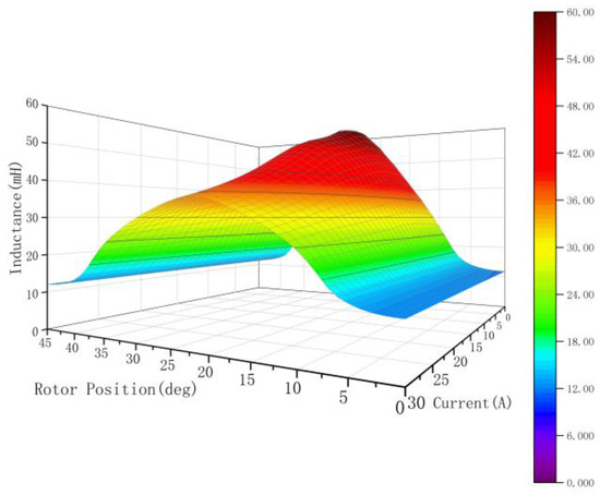
Figure 2.
Nonlinear inductance characteristic curves obtained from finite element analysis.
Based on the electromechanical energy conversion principle, the electromagnetic torque of the SRM is represented as a function of both the angle and current, as illustrated in Figure 3.
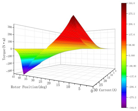
Figure 3.
Nonlinear torque characteristic curves derived from finite element analysis.
The mechanical dynamics of the SRM are described by the following equations:
where is the mechanical angular velocity of the motor, is the rotational inertia of the motor, is the viscous friction factor, is the total electromagnetic torque, and is the load torque.
The overall electromagnetic torque for the three-phase SRM is expressed as follows:
where , , and are the electromagnetic torques of the A, B, and C phases, respectively. In this paper, the sinusoidal torque distribution function is adopted, where the sinusoidal distribution function of the phase torque is expressed as follows:
where is the rotor position angle of each phase; and are the turn-on and turn-off angles, respectively; is the overlap angle of the phase change; and is the rotor angle period. Figure 4 illustrates the block diagram of a three-phase 12/8 SRM control system with traditional TSF, where a PI controller is used as the input for the TSF. The outer loop regulates speed, while the inner loop is responsible for controlling torque in the system. The TSF module generates the torque reference for each phase, while the switching signal is produced by comparing the reference with the actual torque hysteresis loop for each phase.
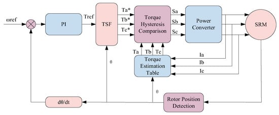
Figure 4.
Block diagram of three-phase 12/8 SRM control with conventional torque sharing function.
3. Conventional LADRC Speed Controller Design
The conventional LADRC speed controller consists of three parts: the linear tracking differentiator (LTD), the LESO, and the LSEF controller. Among them, the LESO is the central component of LADRC, which observes the system’s overall disturbance and performs feedforward compensation to improve the system’s immunity. The mathematical model of the LADRC speed controller is formulated by Equations (7)–(9).
For the LTD,
where is the expected value of ; is the tracking signal of ; is the tracking error of the LTD; and is the velocity factor of the LTD. For the LESO,
where and are the LESO’s observations of and the system perturbation term f, respectively; and are the gain terms in the LESO module; and is the observation error of the state variable .
For LSEF controllers,
where is the error signal of the LSEF; is the linear feedback output; is the final output control signal; and k is the gain term in the LSEF module. In summary, Figure 5 illustrates the block diagram of the conventional first-order LADRC controller.
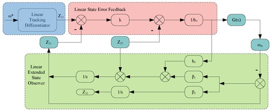
Figure 5.
Block diagram of the structure of a conventional first-order linear active disturbance rejection control (LADRC) controller.
4. ISTSM-LADRC Speed Controller Design
To accelerate the dynamic response of LADRC and further boost the control performance and disturbance rejection capabilities of the controller, the STSM algorithm is applied to the traditional LADRC to optimize the LESO and LSEF. The STSM is combined with the LESO, and an STSM-LESO is developed to monitor the system disturbances. The original LSEF control law is replaced by the STSM algorithm, which further enhances the system’s dynamic response performance. In LADRC, the LTD is responsible for extracting differential signals and managing the transition process. However, in the first-order LADRC, the LTD outputs to the LESO without performing differentiation. To improve real-time performance and simplify parameter tuning, the LTD link is eliminated, reducing the complexity in the control system.
4.1. STSM Algorithm
The STSM algorithm is a special algorithm in second-order SMC. It adopts the concept of super-twisting control, where only the information of the sliding mode variables needs to be known, rather than the first-order derivative of . The STSM control defines the derivative at discontinuous moments as a continuous function of the sliding mode variable, thereby effectively suppressing sliding mode chattering. Its trajectory significantly differs from the traditional twisting algorithm as it spirals around the origin, with the amplitude decreasing geometrically as the coordinate axis changes. This approach can effectively reduce sliding mode chattering. In super-twisting control, different control methods are applied depending on the error value. When the error is small, the controller uses traditional sliding mode control; when the error is large, the controller improves control accuracy by adjusting the super-helix motion mode. Compared with traditional sliding mode control, the STSM algorithm uses integration to obtain the actual control quantity without high-frequency switching. It effectively suppresses system jitter and offers faster response speed and stronger robustness. For a single-input nonlinear system, there exists a relationship as shown in Equation (10):
where x is the state variable; u is the input; y is the output; and are the unknown functions of the sliding mode variable structure; and is the unknown sliding mode surface function.
Let the sliding mode variable , be the reference signals. Then, the expression for the STSM control algorithm is given by
where and are the state variables and , , and are parameters to be designed. From Equation (11), it can be seen that the STSM control algorithm is mainly composed of two parts. The first component represents the nonlinear discontinuous function of the sliding mode variable, which can be adjusted by modifying the index to optimize the control performance. The second component is the integral term, which improves the robustness of the system by enabling second-order sliding mode control to be less sensitive to parameter variations. This adjustment helps reduce inherent system jitter and ensures better stability and performance under various operating conditions. Typically, is taken as 0.5.
4.2. STSM-LESO Design
The LESO is the central component of the LADRC. Its primary function is to monitor the total disturbance in the system and apply feedforward compensation, thereby enhancing the disturbance rejection capability of the LADRC controller. In this section, an STSM-LESO is proposed, using the STSM algorithm for the speed tracking error signal in the LESO so that it can converge to zero quickly. Therefore, the observation performance of the LESO can be enhanced by combining the STSM variable structure principle, which further boosts control performance and disturbance immunity, thereby enhancing the SRM system’s efficiency.
Firstly, the sliding mode surface function for the error is defined as follows:
where is the observation error of the state variable , the speed tracking error of the observer, and is the first-order derivative of . By combining Equations (11) and (12), the STSM algorithm is used to obtain
Then the STSM-LESO design is
where and are gain terms. The traditional STSM algorithm uses the sign function. Due to the discontinuity of the sign function, it causes a sudden change in the control input when the system switches, which leads to jitter in the system. To minimize system vibrations, the sign function is replaced by a continuous and smooth sigmoid function, which is expressed as follows:
As illustrated in Figure 6, when k = 10, the sigmoid function exhibits significant oscillations as it approaches zero; conversely, when k = 0.5, the sigmoid function shows a smaller amplitude and decays more gradually. To achieve a balance between the smoothness of the sigmoid function and the system’s response speed, this paper selects k = 1, which effectively mitigates system chattering while maintaining a satisfactory response speed.
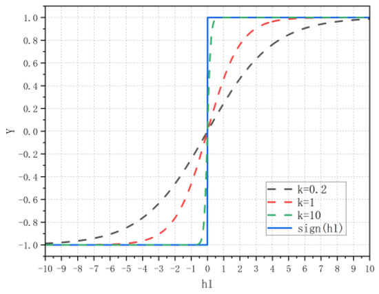
Figure 6.
Comparison of sign function and sigmoid function graphs.
Figure 7 illustrates the block diagram of the enhanced STSM-LESO structure, with the principle described in Equation (16):
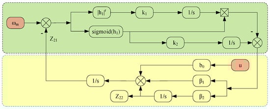
Figure 7.
Block diagram of improved super-twisting sliding mode and linear extended state observer (ISTSM-LESO) structure.
4.3. STSM-LSEF Control Law Design
After the observation estimation of perturbation and feedforward compensation by the STSM-LESO, the control system can be considered equivalent to an integrator. The LSEF control is similar to the proportional control in proportional–integral controllers. In the case of a fast dynamic response of the system, if the deviation in the LSEF design is too large, it may lead to overshooting and oscillations, which decreases the stability and robustness of the system. To solve this problem, the STSM algorithm is incorporated into the LSEF control law to enhance system stability and robustness, taking advantage of its fast response and insensitivity to parameter variations and disturbances.
Firstly, the following defines the sliding mode surface function:
where is the error signal of the LSEF and is the first-order derivative of . By combining Equations (11), (15) and (17), we obtain
Combining Equations (17) and (18) yields the expression of the STSM-LSEF control law, as shown in Equation (19):
Its block diagram is shown in Figure 8.
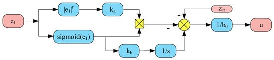
Figure 8.
Block diagram of improved super-twisting sliding mode and linear state error feedback (ISTSM-LSEF) structure.
In summary, Figure 9 illustrates the block diagram of the ISTSM-LADRC speed controller.
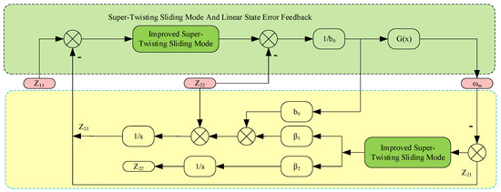
Figure 9.
Block diagram of the structure of the ISTSM-LADRC speed controller.
4.4. Stability Analysis
To prove the stability of the designed STSM-LESO, a Lyapunov function is selected.
Differentiating Equation (20) gives the following expression:
To ensure stability, the new sliding mode convergence law must satisfy the condition given by Equation (22).
By substituting Equations (13) and (15) into Equation (21), the result is the expression shown in Equation (23):
From Figure 6, it can be observed that both and the function share the same sign. Specifically, when , the value of remains positive. When k1 > 0 and k2 > 0, , and . Consequently, is always negative. Moreover, since and have opposite signs, it follows that . Similarly, when , is always positive, ensuring . In the case where , , resulting in . We conclude that
In summary, these observations confirm that the designed STSM-LESO is stable. Similarly, it can be demonstrated that the stability of the designed STSM-LSEF control law is the same as the above, and it is also stable.
5. Simulation Analysis
Using the motor drive parameters from Table 1, a corresponding system simulation model was developed in MATLAB/Simulink (version 23.2.0.2365128, R2023b). The simulations were conducted on a laptop with the following specifications: AMD Ryzen 7 8845HS CPU (eight cores), 24 GB of RAM (5600 MHz). In this study, three control strategies are analyzed: the PI strategy, the STSM strategy, and the ISTSM-LADRC strategy proposed herein. The turn-on angle and turn-off angle of the three-phase 12/8 SRM are set to 5° and 20°, respectively. The PI control strategy parameters are set as = 0.12 and = 2.7. For the STSM strategy, the parameters are set as k1 = 1.5 and k2 = 200. In the ISTSM-LADRC strategy, the controller parameters are set as k1 = 3, k2 = 1600, = 1, = 0.1, b0 = 10, and r = 0.5. These strategies are evaluated under variable load and speed conditions, with a focus on analyzing torque ripple.

Table 1.
Parameters of the SRM.
To assess the robustness of the three control strategies for the SRM in response to sudden load changes, a load test is conducted on the SRM. The simulation time is set to 1 s. With operating speeds of 500 rpm and 1000 rpm, the load torque increases from 5 Nm to 10 Nm in 0.25 s, and then decreases from 10 Nm to 8 Nm over 0.75 s. A comparison of the speed waveforms for the three control strategies is presented in Figure 10.
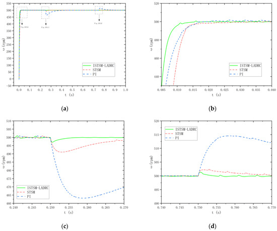
Figure 10.
Speed waveforms under three control strategies at a given speed of 500 rpm: (a) velocity waveforms; (b) local enlargement of velocity waveform I; (c) local enlargement of velocity waveform II; and (d) local enlargement of velocity waveform III.
The oscillation amplitude coefficient during SRM operating condition changes is defined as
In the equation, represents the oscillation amplitude coefficient; represents the maximum amplitude of the oscillation; and is the given speed.
As shown in Figure 10b, there is virtually no overshoot in the motor startup stage for all three control strategies, indicating that all strategies exhibit good control performance. Among them, the traditional PI strategy has a settling time of 0.019 s during startup, the STSM strategy achieves a settling time of 0.017 s, and the ISTSM-LADRC strategy proposed in this paper achieves a settling time of 0.014 s. As seen in Figure 10c, when the load torque is suddenly increased from 5 Nm to 10 Nm in 0.25 s, the system speed under the PI strategy decreases to 463 rpm and has a recovery time of 0.138 s. Under the STSM strategy, the system speed decreases to 491 rpm with a recovery time of 0.038 s. Under the ISTSM-LADRC strategy, the system speed decreases to 497 rpm with a recovery time of 0.007 s. As shown in Figure 10d, when the load torque is reduced from 10 Nm to 8 Nm at 0.75 s, the system speed increases to 514 rpm under the PI strategy with a recovery time of 0.12 s. Under the STSM strategy, the system speed rises to 503 rpm with a recovery time of 0.022 s, and under the ISTSM-LADRC strategy, the system speed rises to 501.2 rpm with a recovery time of 0.005 s.
For a given operating speed of 1000 rpm, the load torque is suddenly increased from 5 Nm to 10 Nm at 0.25 s, and then reduced from 10 Nm to 8 Nm at 0.75 s. A comparison of the speed waveforms for the three control strategies is shown in Figure 11.
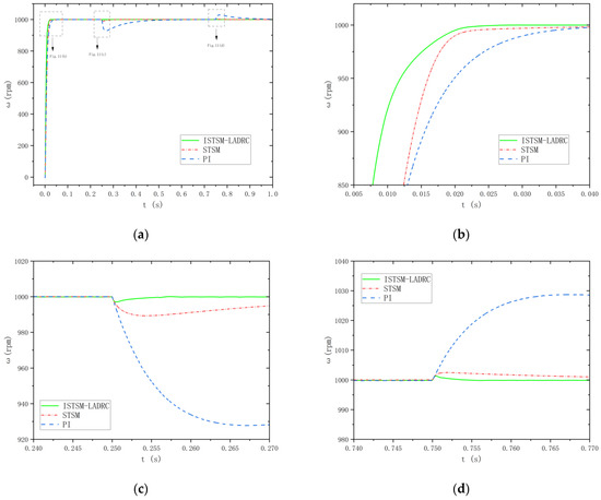
Figure 11.
Speed waveforms under three control strategies at a given speed of 1000 rpm: (a) velocity waveforms; (b) local enlargement of velocity waveform I; (c) local enlargement of velocity waveform II; and (d) local enlargement of velocity waveform III.
As shown in Figure 11b, the traditional PI strategy has a settling time of 0.039 s during startup, the STSM strategy has a settling time of 0.027 s, and the ISTSM-LADRC strategy proposed in this paper has a settling time of 0.024 s. As shown in Figure 11c, when the load torque is suddenly increased from 5 Nm to 10 Nm in 0.25 s, the system speed under the PI strategy drops to 929 rpm and has a recovery time of 0.198 s. Under the STSM strategy, the system speed decreases to 989 rpm with a recovery time of 0.038 s, and under the ISTSM-LADRC strategy, the system speed decreases to 997 rpm with a recovery time of 0.007 s. As shown in Figure 11d, when the load torque is abruptly reduced from 10 Nm to 8 Nm at 0.75 s, the system speed increases to 1028 rpm under the PI strategy with a recovery time of 0.213 s. Under the STSM strategy, the system speed rises to 1003 rpm with a recovery time of 0.032 s, and under the ISTSM-LADRC strategy, the system speed rises to 1001.5 rpm with a recovery time of 0.004 s.
Table 2 summarizes the aforementioned data and compares the oscillation amplitude coefficients of the three control strategies under load fluctuation conditions.
Table 2.
Oscillation amplitude coefficients of the three control strategies under load fluctuation conditions.
In summary, compared to the STSM strategy and the traditional PI strategy, the ISTSM-LADRC strategy introduced in this paper exhibits a superior dynamic response capability and control performance.
The advantage of ISTSM-LADRC in handling dynamic disturbances stems from its integration of the robustness of sliding mode control, the active disturbance estimation capability of LADRC, and the smooth control characteristics of the sigmoid function. This enables the strategy to respond quickly and smoothly to external disturbances, nonlinearities, or system uncertainties, thereby enhancing the system’s stability and control performance.
Firstly, it can be observed that from startup to stabilization at the set speed, the system using the ISTSM-LADRC strategy effectively suppresses speed overshooting and reaches the desired speed more quickly, demonstrating excellent dynamic performance. As shown in Figure 12c, when the load torque is 5 Nm and the rotational speed changes abruptly from 500 rpm to 1000 rpm in 0.25 s, the response times for the PI and STSM strategies are 0.158 s and 0.015 s, respectively. In comparison, under the ISTSM-LADRC strategy, the response time for the motor to reach 1000 rpm from 500 rpm is 0.013 s. As shown in Figure 13c, when the load torque is 10 Nm, the response times for the PI, STSM, and ISTSM-LADRC strategies are 0.107 s, 0.013 s, and 0.011 s, respectively.
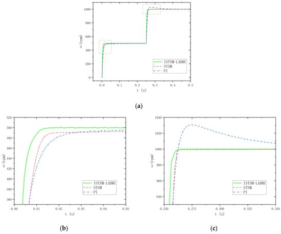
Figure 12.
The waveforms of the motor under a sudden speed change with a 5 Nm load are shown. (a) Velocity waveforms; (b) local enlargement of velocity waveform I; and (c) local enlargement of velocity waveform II.
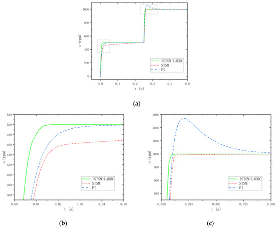
Figure 13.
The waveforms of the motor under a sudden speed change with a 10 Nm load are shown. (a) Velocity waveforms; (b) local enlargement of velocity waveform I; and (c) local enlargement of velocity waveform II.
This indicates that the system based on the ISTSM-LADRC strategy effectively reduces the influence of load changes on system performance, further confirming its ability to enhance system robustness.
The torque ripple coefficient of the SRM during steady-state operation is defined as follows:
In the equation, represents the torque ripple coefficient; is the maximum torque; is the minimum torque; and is the given torque.
Figure 14 and Figure 15 show the three-phase current and torque waveforms of the SRM when it is in a steady state under working conditions with a load torque of 10 Nm and set speeds of 500 r/min and 1000 r/min. Table 3 presents the torque ripple coefficients for the three control strategies. In the STSM-LADRC strategy, the smooth sigmoid function is used to replace the non-smooth sign function. By providing smoother control inputs and offering continuous adjustments when the input signal changes, it avoids abrupt jumps and excessive switching. This reduces high-frequency switching and chattering, effectively suppresses torque ripple, and enhances the overall stability of the system. It can be seen that compared with the PI control strategy and SMC strategy, the STSM-LADRC strategy has a smaller torque ripple and effectively suppresses torque ripple, so the control effect is significantly superior.
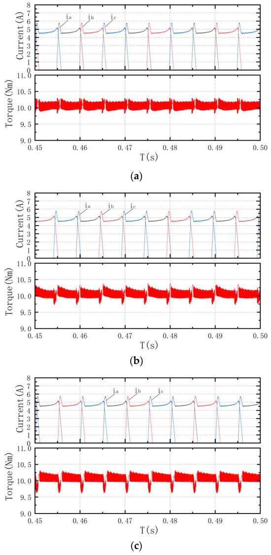
Figure 14.
Steady-state waveforms at 500 r/min under 10 Nm: (a) ISTM-LADRC strategy; (b) Sliding mode control (SMC) strategy; and (c) Portional integral (PI) control strategy.
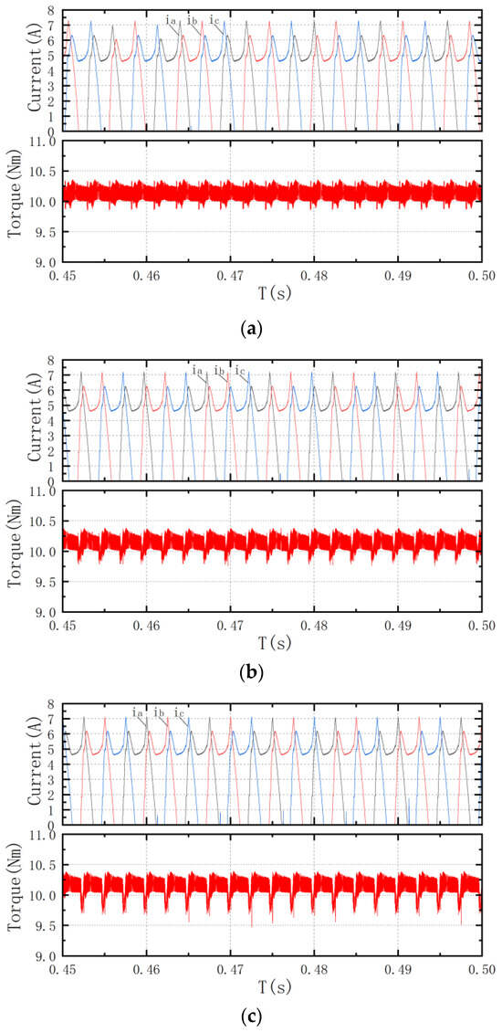
Figure 15.
Steady-state waveforms at 1000 r/min under 10 Nm: (a) ISTM-LADRC strategy; (b) SMC strategy; and (c) PI control strategy.
Table 3.
Comparison of the motor’s steady-state operation under a 10 Nm load.
6. Conclusions
This paper proposes an ISTSM-LADRC strategy to improve the dynamic response, disturbance rejection, and overall control performance of the SRM system, aiming to enhance its robustness and efficiency. This strategy utilizes the STSM variable structure principle to optimize the LESO and LSEF in the LADRC controller. The sigmoid function replaces the sign function, significantly reducing the inherent jitter of the sliding mode and improving the system’s stability.
The PI, STSM, and ISTSM-LADRC strategies were compared and analyzed through simulations under variable load conditions, and the torque ripple for the three control strategies at different speeds was examined. The ISTSM-LADRC strategy proposed in this paper demonstrates superior dynamic response performance and enhanced anti-disturbance capability. The STSM-LESO exhibits a strong tracking ability to disturbances in the system. Compared with the traditional PI and STSM strategies, the ISTSM-LADRC strategy results in smaller speed fluctuations and faster responses under variable load conditions. Furthermore, the ISTSM-LADRC strategy more effectively suppresses torque ripple than the other two control strategies.
Author Contributions
Algorithm design, J.Z. and S.C.; coding and testing, J.Z. and L.Z.; design of the control system, J.Z. and S.C.; article review and proofreading, C.L. and S.C.; funding acquisition, C.L. All authors have read and agreed to the published version of the manuscript.
Funding
This work was supported by the Jilin Province High-power Power Electronics Technology and Parallel Robot Technology Innovation Team of the Department of Science and Technology of Jilin Province (20190101018JH) and “Research on Control Strategy of Switched Reluctance Motors for Electric Vehicles” of the Postgraduate Innovation Project of Beihua University (YCHZ [2024] 017).
Data Availability Statement
Data are contained within this article.
Conflicts of Interest
The authors declare no conflicts of interest.
References
- Abdel-Aziz, A.A.; Ahmed, K.H.; Wang, S.; Massoud, A.M.; Williams, B.W. A neutral-point diode-clamped converter with inherent voltage-boosting for a four-phase SRM drive. IEEE Trans. Ind. Electron. 2019, 67, 5313–5324. [Google Scholar] [CrossRef]
- Diao, K.; Sun, X.; Lei, G.; Guo, Y.; Zhu, J. Multimode optimization of switched reluctance machines in hybrid electric vehicles. IEEE Trans. Energy Convers. 2020, 36, 2217–2226. [Google Scholar] [CrossRef]
- Liu, P.; Wang, T.; Chai, Z.; Liu, C.; Zhu, X. Optimized Parking Control for Electric Vehicle Driven by Switched Reluctance Motor. IEEE Access 2023, 11, 130719–130732. [Google Scholar] [CrossRef]
- Naeini, V. Principle and design of a novel axial flux-switched reluctance motor with short flux path. Int. Trans. Electr. Energy Syst. 2019, 29, e2760. [Google Scholar] [CrossRef]
- Jing, B.; Dang, X.; Liu, Z.; Long, S. Torque ripple suppression of switched reluctance motor based on fuzzy indirect instant torque control. IEEE Access 2022, 10, 75472–75481. [Google Scholar] [CrossRef]
- Nalinashini, G.; Tamilselvi, V. Experimental investigation of modified in-wheel switched reluctance motor with reduced torque ripple for electric vehicles. Electr. Eng. 2021, 103, 2837–2845. [Google Scholar] [CrossRef]
- Wei, Z.; Zhao, M.; Liu, X.; Lu, M. Speed control for SRM drive system based on switching variable proportional desaturation PI regulator. IEEE Access 2021, 9, 69735–69746. [Google Scholar] [CrossRef]
- Selvi, R.K.; Malar, R.S.M. A bridgeless Luo converter based speed control of switched reluctance motor using Particle Swarm Optimization (PSO) tuned proportional integral (Pi) controller. Microprocess. Microsyst. 2020, 75, 103039. [Google Scholar] [CrossRef]
- Ma, M.; Ling, F.; Li, F.; Liu, F. Torque ripple suppression of switched reluctance motor by segmented harmonic currents injection based on adaptive fuzzy logic control. IET Electr. Power Appl. 2020, 14, 325–335. [Google Scholar] [CrossRef]
- Li, X.; Liu, J.; Ge, L.; Zhong, J.; Huang, J.; Zhao, Y.; Song, S. Sensorless control of the switched reluctance motor based on the sliding-mode observer. J. Electr. Eng. Technol. 2023, 18, 981–989. [Google Scholar] [CrossRef]
- Feng, L.; Sun, X.; Yang, Z.; Diao, K. Optimal torque sharing function control for switched reluctance motors based on active disturbance rejection controller. IEEE ASME Trans. Mechatron. 2023, 28, 2600–2608. [Google Scholar] [CrossRef]
- Han, G.; Lu, Z.; Hong, J.; Wu, M.; Xu, S.; Zhu, B. Speed synchronization control of dual-SRM drive with ISMC-based cross-coupling control strategy. IEEE Trans. Transp. Electrif. 2022, 9, 2524–2534. [Google Scholar] [CrossRef]
- Haq, I.U.; Khan, Q.; Ullah, S.; Khan, S.A.; Akmeliawati, R.; Khan, M.A.; Iqbal, J. Neural network-based adaptive global sliding mode MPPT controller design for stand-alone photovoltaic systems. PLoS ONE 2022, 17, e0260480. [Google Scholar] [CrossRef] [PubMed]
- Sehab, R.; Akrad, A.; Saadi, Y. Super-twisting sliding mode control to improve performances and robustness of a switched reluctance machine for an electric vehicle drivetrain application. Energies 2023, 16, 3212. [Google Scholar] [CrossRef]
- Zhao, X.-M.; Gong, Y.-W.; Jin, H.-Y.; Xu, C. Adaptive super-twisting-based nonsingular fast terminal sliding mode control of permanent magnet linear synchronous motor. Trans. Inst. Meas. Control 2023, 45, 3057–3066. [Google Scholar] [CrossRef]
- Xu, D.; Ding, B.; Jiang, B.; Yang, W.; Shi, P. Nonsingular fast terminal sliding mode control for permanent magnet linear synchronous motor via high-order super-twisting observer. IEEE ASME Trans. Mechatron. 2021, 27, 1651–1659. [Google Scholar] [CrossRef]
- Zhou, X.; Wang, C.; Ma, Y. Vector speed regulation of an asynchronous motor based on improved first-order linear active disturbance rejection technology. Energies 2020, 13, 2168. [Google Scholar] [CrossRef]
- Li, S.; Wang, H.; Li, H.; Yang, C. PMSM sliding mode control based on novel reaching law and extended state observer. Adv. Mech. Eng. 2022, 14, 16878132221119960. [Google Scholar] [CrossRef]
- Zhu, C.; Tu, Q.; Jiang, C.; Pan, M.; Huang, H.; Tu, Z. Global fast terminal sliding mode control strategy for permanent magnet synchronous motor based on load torque Luenberger observer. IEICE Electron. Express 2021, 18, 20210348. [Google Scholar] [CrossRef]
- Li, Z.; Wang, J.; Wang, S.; Feng, S.; Zhu, Y.; Sun, H. Design of sensorless speed control system for permanent magnet linear synchronous motor based on fuzzy super-twisted sliding mode observer. Electronics 2022, 11, 1394. [Google Scholar] [CrossRef]
- Wang, Y.; Sun, T.; Yang, J. Super-twisting nonsingular terminal sliding mode-based robust impedance control of robots. Complexity 2022, 2022, 9263699. [Google Scholar] [CrossRef]
- Qu, F.; Hu, H.; Xu, R.; Chen, Y.; Peng, L.; Yan, J.; Xiao, W.; Yuan, J. Super-Twisted Sliding Mode Control for Maximum Power Point Tracking of Wind Turbine Based on Neural Network. J. Circuits Syst. Comput. 2023, 32, 2350315. [Google Scholar] [CrossRef]
- Scalcon, F.P.; Fang, G.; Vieira, R.P.; Gründling, H.A.; Emadi, A. Discrete-time super-twisting sliding mode current controller with fixed switching frequency for switched reluctance motors. IEEE Trans. Power Electron. 2021, 37, 3321–3333. [Google Scholar] [CrossRef]
- Zhang, Z.; Chen, Y.; Feng, X.; Xie, S.; Zhao, C. Linear active disturbance rejection speed control with variable gain load torque sliding mode observer for IPMSMs. J. Power Electron. 2022, 22, 1290–1301. [Google Scholar] [CrossRef]
- Sun, X.; Xiong, Y.; Yao, M.; Tang, X.; Tian, X. A unified control method combined with improved TSF and LADRC for SRMs using modified grey wolf optimization algorithm. ISA Trans. 2022, 131, 662–671. [Google Scholar] [CrossRef]
- Ben, T.; Wang, H.; Chen, L.; Zhang, Y.; Jing, L. Torque ripple reduction strategy for switched reluctance motor based on segmented non-linear correction torque sharing function. J. Power Electron. 2024, 24, 1933–1943. [Google Scholar] [CrossRef]
Disclaimer/Publisher’s Note: The statements, opinions and data contained in all publications are solely those of the individual author(s) and contributor(s) and not of MDPI and/or the editor(s). MDPI and/or the editor(s) disclaim responsibility for any injury to people or property resulting from any ideas, methods, instructions or products referred to in the content. |
© 2025 by the authors. Licensee MDPI, Basel, Switzerland. This article is an open access article distributed under the terms and conditions of the Creative Commons Attribution (CC BY) license (https://creativecommons.org/licenses/by/4.0/).