Abstract
Grid-forming wind-storage systems can serve as black-start power sources capable of autonomously establishing voltage and frequency references when the external grid is unavailable, thereby providing crucial support for rapid grid restoration. However, during the black-start process, energizing unloaded transformers often induces severe magnetizing inrush currents, which may cause transient overcurrent, damage grid-forming converters, and compromise system stability. To address this issue, this paper proposes a segmented zero-voltage start strategy and a dual-side converter multi-mode switching control scheme based on small-capacity distributed energy storage. First, the formation mechanism of transformer magnetizing inrush under no-load energization is analyzed. A segmented zero-voltage start module is embedded into the outer voltage loop of the virtual synchronous generator (VSG) controller to enable a smooth rise in output voltage, effectively mitigating transient impacts caused by magnetic core saturation. Second, considering the operating requirements during self-start and load restoration stages, a coordinated control framework for dual-side converters is designed to achieve dynamic voltage, frequency, and power regulation with limited energy storage capacity, thereby improving transient stability and energy utilization efficiency. Finally, real-time hardware-in-the-loop (HIL) simulations conducted on an RT-LAB platform verify the feasibility of the proposed control strategy. The results demonstrate that the method can significantly suppress magnetizing inrush current, transient overvoltage, and overcurrent, thus enhancing the success rate and dynamic stability of black-start operations in grid-forming wind-storage systems.
1. Introduction
Against the backdrop of the steady advancement of the national “dual-carbon” targets, the black-start process of power systems following large-scale outages is gradually transitioning from reliance on conventional synchronous generators to inverter-based renewable generation units dominated by power electronic converters [1,2]. However, renewable units inherently lack the ability to establish system voltage and frequency references, making them unsuitable for black-start operation in their native form. The emergence of grid-forming control (GFM) has endowed renewable energy converters with the ability to autonomously generate voltage and frequency references, thereby enabling them to function as independent black-start power sources [3].
As the penetration level of wind power continues to rise, wind turbine generators—owing to their renewable nature and potential dispatchability—have emerged as promising candidates for black-start applications [4]. Nevertheless, the inherent intermittency and variability of wind resources, coupled with weak-grid characteristics caused by long-distance transmission [5], make it difficult for stand-alone wind turbines to achieve a stable black start. To address this challenge, researchers have proposed combining GFM-based converters with energy storage systems [6], forming wind-storage coordinated systems that can provide active power balancing and transient stability support, thus offering a feasible pathway for integrating renewable resources into power system black-start operations [7,8]. One major challenge is the magnetizing inrush current generated when energizing unloaded transformers, which can reach six to eight times the rated current and cause severe electromagnetic stress, voltage fluctuations, and even converter failures [9,10]. Existing studies on magnetizing inrush current have proposed diverse solutions: Reference [11] uses a GSA-BP network-based identification method to improve transformer protection performance; Reference [12] presents a magnetic flux matching method for V/V traction transformers (verified via PSCAD/EMTDC simulations and laboratory tests) to mitigate inrush current; Reference [13] adjusts excitation current parameters (based on magnetization curves) to stabilize generator output under low constant speed; and Reference [14] adopts first–tenth harmonic phase detection for inrush current identification, though it increases algorithm complexity due to large computational load. Most studies on transformer inrush suppression focus on structure optimization, including improving core materials, or signal identification covering harmonic extraction. Despite progress in mechanism analysis and protection design, research on active inrush suppression at the control level remains insufficient and hardly adapts to complex grids.
Recent research on grid-forming converters has provided new control-oriented solutions for black start [15,16,17]. Representative works include the development of reactive power synchronization for PV plants [18], voltage ramp-up control using ESS [19], and rotor-flux-oriented control for DFIG-based wind turbines [20]. In VSC-HVDC systems, extending the voltage rise duration has also proven effective for reducing inrush [21]. Collectively, these works highlight the potential of control-based inrush suppression within grid-forming frameworks [22]. In addition, the black-start process typically involves two stages: self-start and load restoration. The latter may introduce transient overvoltage, frequency dips, and power oscillations, requiring systematic coordination between renewable and storage units. Prior works have proposed hierarchical optimization [23], adaptive power allocation [24], and predictive voltage regulation [25] to maintain stability and state-of-charge balance. Reference [26] proposed a VSG inverter control scheme with black-start, islanded operation and parallel grid connection, and validated its dynamic stability in multiple scenarios via a microgrid model. Reference [27] presented an MPC-based coordinated voltage regulation method for wind-thermal hybrid systems, realizing stable voltage restoration and reasonable reactive power distribution in black-start recovery. Reference [28] focuses on extreme weather in offshore wind farms. Conventional grid-following (GFC) control in such context tends to cause reactive power instability, overvoltage [29], and thus a lack of black-start capability. It therefore studies integrating black-start into offshore wind farms via grid-forming (GFM) energy storage systems. Reference [30] proposes and develops a novel three-mode PID controller based on grid-connected, black-start, and islanded modes, which switches control strategies per operating mode. Reference [31] proposes a suppression scheme based on superconducting coils to enhance the system’s overvoltage resistance, aiming to address the ferroresonant overvoltage issue in doubly fed induction generators (DFIGs). In summary, suppressing transformer magnetizing inrush current and maintaining dynamic stability of voltage, frequency, and power throughout the entire black-start process (from self-start to load restoration) are two core technical challenges for realizing safe and reliable black-start of grid-forming renewable energy systems.
To address these challenges, this paper proposes an enhanced grid formation control strategy for wind-storage systems with small-capacity distributed energy storage. This method introduces a multi-mode switching scheme of segmented zero-voltage startup and grid-connected wind turbine bilateral converter to suppress inrush current and maintain dynamic voltage–frequency stability throughout the black-start process.
- (1)
- A segmented zero-voltage-start strategy is embedded in the VSG outer loop to achieve a smooth voltage buildup, effectively mitigating transformer saturation and magnetizing inrush, thereby improving transient stability during the initial stage of black start.
- (2)
- A dual-side converter control framework enables dynamic switching between MPPT control and constant-power/constant-voltage modes, ensuring autonomous startup, load restoration, and power balance with small-capacity distributed storage.
- (3)
- Hardware-in-the-loop validation on an RT-LAB platform confirms that the proposed strategy suppresses inrush current, overvoltage, and frequency oscillations, enhancing voltage and power stability during black-start restoration.
The remainder of this paper is organized as follows: Section 2 introduces the VSG-based grid-forming control principle of the permanent magnet synchronous generator (PMSG). Section 3 presents the proposed segmented zero-voltage-start strategy and multi-mode switching control framework. Section 4 details the overall black-start scheme and procedure. Section 5 validates and analyzes the proposed strategy through hardware-in-the-loop experiments, and Section 6 concludes the paper and summarizes the main findings.
2. System Topology and Grid-Forming Control Strategy of the Wind-Storage System
2.1. Topology of the Wind-Storage System
The topology of the wind-storage coordinated grid-connected system is illustrated in Figure 1. It primarily consists of a PMSG, a battery energy storage system (BESS), a full-scale power converter, and the AC grid. The storage unit adopts a distributed configuration, suitable for regions where only small-capacity energy storage can be directly connected to the wind turbine DC link. This setup ensures flexible configuration and maintains power balance within the turbine.
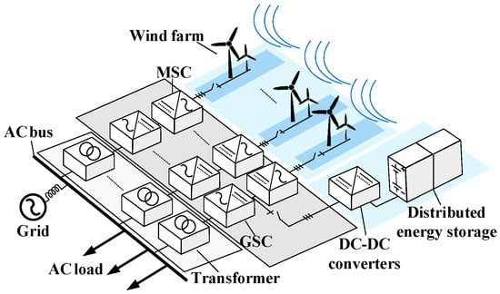
Figure 1.
Topology of the wind-storage coordinated grid-connected system.
As shown in Figure 1, the BESS is connected in parallel with the machine-side converter (MSC) through a bidirectional DC–DC converter. The combined DC bus links to the grid-side converter (GSC) and then to the grid via the transformer T. The AC loads are connected to the common AC bus, enabling coordinated operation between wind generation and storage.
2.2. Control of the PMSG Machine-Side Converter
In grid-forming wind-storage systems used as black-start power sources, the MSC of the wind turbine typically operates under the maximum power point tracking (MPPT) strategy during normal operation to maximize wind energy utilization. Meanwhile, the GSC is responsible for grid-forming functions—regulating active power output while establishing voltage and frequency references.
The MSC is primarily tasked with stabilizing the DC-link voltage. Its inner current-control loop follows a conventional decoupled dq-frame structure. In the outer control loop, the d-axis current reference is set to zero, while the q-axis current reference is obtained from the deviation of the DC-link voltage processed by a PI regulator. This ensures steady DC voltage regulation.
The reference currents of the generator in dq coordinates can be expressed as
where Udc* and Udc denote the reference and actual DC-link voltages, respectively, and kp1 and ki1 are the proportional and integral gains of the voltage regulator. At this point, the inner-loop control expression of the machine-side converter can be rewritten as follows:
where kp2 and ki2 are the proportional and integral adjustment gains of the current inner loop, respectively; isd and isq are the actual dq-axis components of the wind turbine stator current; Rs is the stator resistance; Lsd and Lsq are the equivalent dq-axis inductances; ωr is the stator angular velocity; ψf is the stator flux linkage; usd and usq are the dq-axis components of the wind turbine stator voltage; and θr is the machine-side reference phase. From Equations (1) and (2), the control block diagram of the grid-forming PMSG machine-side converter is obtained, as illustrated in Figure 2.
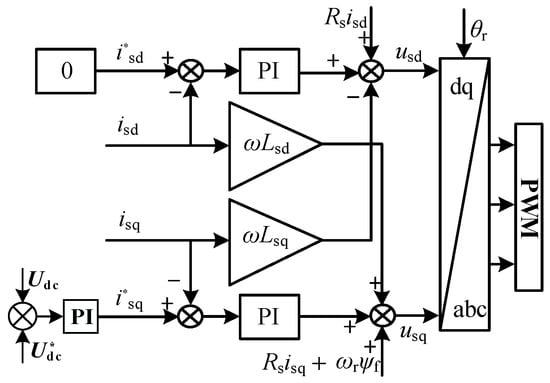
Figure 2.
Machine-side converter control.
2.3. Control of the PMSG Grid-Side Converter
The grid-side converter adopts virtual synchronous generator (VSG) control to actively establish voltage and frequency references. The core mechanism is to emulate the electromechanical dynamics of a synchronous generator by embedding a virtual swing equation and excitation system into the converter controller. This provides the system with virtual inertia and damping characteristics, enhancing stability during the black-start process.
The active-power and frequency dynamics are governed by the virtual swing equation:
where J is the virtual inertia coefficient, D is the damping coefficient, Pm and Pe are the mechanical and electrical power, ω is the output angular velocity of the converter, ω0 is the grid angular velocity, ωref is the rated angular velocity, and θref is the reference value of the output phase angle between the converter and the grid.
The reactive-power and voltage control emulate the excitation system of a synchronous generator through a PI regulator:
where kp and ki are the proportional coefficient and integral coefficient, respectively, Xe is the virtual inductance ie is the virtual excitation current, Dq is the reactive power droop coefficient, Qref is the reference reactive power, Uref is the reference voltage, Qe is the reactive power output by the inverter, and U is the amplitude of the inverter output voltage.
Based on the automatic voltage regulation (AVR) mechanism, the converter reference voltage vector can be computed as
Combining the active-frequency and reactive-voltage loops yields the complete VSG-based grid-side converter control structure, as shown in Figure 3.
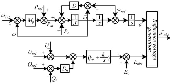
Figure 3.
Grid-side converter control.
3. Improved Black-Start Control Strategy for Grid-Forming Wind-Storage Systems
3.1. Mechanism of Magnetizing Inrush During No-Load Transformer Energization
During the black-start process, excessively fast voltage establishment by the grid-forming converter often leads to magnetic flux saturation in the main transformer. When the main transformer undergoes no-load closing, significant magnetizing inrush current is induced, which exerts adverse effects on the wind-storage system acting as the black-start power source. Since the transformer is equipped with an excitation branch, and the excitation current only flows through the side where the transformer is closed and energized, the primary winding voltage during the no-load charging of the transformer is expressed as follows:
where U is the voltage amplitude on the energized side of the transformer, θ0 is the initial phase angle during no-load closing, i1 and N1 are the excitation current and the number of winding turns on the energized side of the transformer, respectively, Rm is the winding resistance on the energized side of the transformer, and φ is the magnetic flux linked with the winding on the energized side of the transformer. The excitation current can be expressed as follows:
where Lm is the inductance of the winding on the energized side of the transformer.
Substituting Equation (6) into Equation (7) yields the main magnetic flux φ as follows:
where φstable denotes the steady-state component of magnetic flux and φoffset denotes the transient component of magnetic flux with decaying offset. They can be expressed separately as follows:
where γ is the impedance angle of the winding on the energized side of the transformer and φ* is the residual magnetic flux of the transformer.
It can be inferred from Equations (8) and (9) that once the magnetic flux in the iron core exceeds the saturation flux value, the transformer will quickly enter a deep saturation state. This leads to a sharp drop in the equivalent reactance of the winding on the closing side, thereby causing a rapid surge in the excitation current within an extremely short time. The peak value of this current typically reaches 6–8 times the rated current, which is the phenomenon of magnetizing inrush current.
3.2. Control Strategy for Suppressing Magnetizing Inrush Current
By analyzing the generation mechanism of magnetizing inrush current during transformer no-load energization and considering that the grid-side converter of the PMSG operates under grid-forming VSG control, it becomes essential to precisely regulate both the amplitude and the rate of rise in the output voltage on the grid side of the wind-storage system. A controlled, gradual voltage buildup from zero, following a predefined trajectory, can effectively suppress the magnetizing inrush current induced by transformer core saturation during the closing operation.
To achieve this, a segmented zero-voltage startup module is incorporated into the reactive power–voltage control loop of the VSG. This module allows the output voltage reference to increase smoothly and progressively rather than through a rigid step-rising process. Such a design prevents transformer excitation saturation during no-load energization and mitigates the transient overcurrent effects associated with magnetizing inrush, thereby enhancing system stability during the initial phase of black start.
During the no-load closing process of the main transformer, switch S1 is set to 0 in the reactive power–voltage loop of VSG control. The zero-voltage start module is used to control the output voltage amplitude and rising rate of change in the grid-side converter in the grid-forming wind-storage system. After the no-load pre-magnetization of the transformer is achieved, switch S1 is set to 1 to switch to a constant voltage reference value, providing stable voltage support for the black start of the grid-forming wind-storage system. The output voltage reference value of the PMSG grid-side converter can be expressed as follows:
where t0 is the zero-voltage startup time, t1 and t2 are the startup time of different stages of zero-voltage startup, and U0 is the steady-state output voltage reference amplitude of the grid-connected wind turbine grid-side converter; among them, uref(t) is the reference value of its output voltage, and the piecewise modeling of this value is used to achieve accurate tracking of the reference voltage in VSG control to achieve slow voltage rise. The wind-storage system formed by the power grid first rises to 0.8 U0 along the exponential function curve to establish the voltage, and then rises to the constant voltage setting value 1 (p.u.) along the slope function. The block diagram of the segmented zero-voltage start control is illustrated in Figure 4. As shown in Figure 4, the switch S1 can realize switching constant voltage control and zero-voltage startup module control. In the initial stage of black start, the switch S1 is switched to state 0 after the self-starting of the wind-storage system. At the same time, the no-load transformer is switched to realize zero-voltage startup to suppress the inrush current.
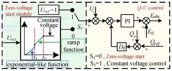
Figure 4.
Zero-Voltage Start Control Block Diagram.
3.3. Improved Black-Start Control Strategy
During the black-start process, the connection and disconnection of different types of loads often induce dynamic phenomena such as transient overvoltage, power fluctuation, and frequency dip. These phenomena severely disrupt the black-start progress and may even result in startup failure.
The black-start system integrates a distributed energy storage unit to mitigate the intermittency and volatility inherent in wind turbine generation. When a grid fault occurs, the energy storage device can rapidly absorb excess DC-link power, thereby maintaining DC bus voltage stability and significantly enhancing the low-voltage ride-through capability of grid-forming wind turbines. However, during the no-load startup phase of the PMSG (when no load is connected), its output active power is fully injected into the energy storage unit. For regions where large-scale energy storage devices are difficult to deploy, how to reduce the required energy storage capacity has become one of the key issues for achieving efficient black starts.
To address the transient issues occurring during the black start of the wind-storage system and reduce the required energy storage capacity, this paper proposes a multi-mode switching control strategy based on small-capacity distributed energy storage, considering the control characteristics of the PMSG’s machine-side and grid-side converters. The overall control framework of this strategy is illustrated in Figure 5.
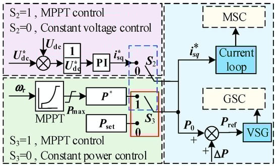
Figure 5.
Control Block Diagram of Multi-Mode Switching for PMSG Dual-Side Converters.
Where Pmax is the maximum power reference value tracked by MPPT control, Pset is the power value set by the constant power control, and Udc* is the given constant DC voltage. By switching the control modes of PMSG machine-side converter and grid-side converter at different stages of black start, the core control support of wind-storage system self-starting and load recovery is realized.
During the no-load self-start stage, when the wind turbine operates without external loads, the MSC adopts MPPT control (switch S2 in position 1) to extract the optimal mechanical power from the wind source. Simultaneously, the GSC operates in constant-power mode (switch S3 in position 0) to limit the active power output and thereby reduce the power exchange demand on the small-capacity energy storage system. This configuration ensures stable DC-link voltage buildup and smooth system energization while preventing excessive stress on the storage unit. Through this adaptive multi-mode switching mechanism, the strategy effectively strengthens transient voltage–frequency stability and maintains uninterrupted power support throughout the entire black-start process.
3.4. Overall Control Framework
Based on the preceding analysis, a comprehensive control strategy for suppressing magnetizing inrush current and a multi-mode switching control framework for the dual-side converters of the PMSG are proposed, as illustrated in Figure 6. The method integrates a segmented zero-voltage startup mechanism into the control architecture, which effectively mitigates the magnetizing inrush current generated during the energization of unloaded transformers in the initial stage of black start. As a result, the grid-forming power source can establish voltage smoothly and provide rapid and stable support for system frequency, voltage, and load power during startup.
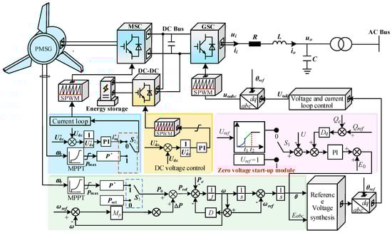
Figure 6.
Grid-Forming Wind-Storage System Overall Control Block Diagram.
Furthermore, through targeted modification and optimization of the control structures of both the machine-side and grid-side converters, a multi-mode switching strategy is developed. This strategy substantially reduces the required capacity of the energy storage system under space-constrained deployment conditions, enabling small-capacity distributed storage to achieve reliable voltage buildup in the early phase of system restoration. During the subsequent load connection process, the control framework dynamically switches operating modes according to real-time system conditions, thereby enhancing the transient stability of critical parameters—including voltage, frequency, and active power—throughout the entire black-start sequence.
4. Black-Start Scheme for Grid-Forming Wind-Storage System
4.1. Principles, Scenarios, and Operating Stages of Black Start
A black start refers to the process of restoring a power system that has suffered a complete outage, using generating units or self-supplied power sources that can operate independently from the external grid. These units, known as black-start power sources, are responsible for re-establishing the system’s voltage and frequency references, sequentially energizing other facilities, and ultimately restoring the entire grid area.
Under extreme events such as natural disasters, equipment faults, or human-induced incidents, the grid may undergo a complete shutdown, causing wind turbines to disconnect from the network and remain in an idle state. To facilitate system recovery, the wind turbines must be capable of autonomous self-start in islanded mode, providing stable voltage and frequency support. Through grid-forming control, the wind turbine converters can rapidly build up these references, fulfilling the essential condition for serving as black-start units and ensuring that subsequent restoration proceeds without secondary disturbances.
The black-start operation of grid-forming wind turbines typically comprises two main stages:
- (1)
- Power Source Self-Start Stage:
The self-start phase is the initial stage of the regional power grid composed of the wind-storage system. This phase commences when the wind speed reaches the cut-in wind speed of the wind turbine. During this period, the wind turbine, in collaboration with the energy storage system, can efficiently complete the self-start process. The successful implementation of this phase lays the foundation for subsequent grid restoration, providing reliable support for the subsequent establishment of system voltage and frequency. Through this mechanism, the wind turbine can start independently without relying on the external grid and gradually form a stable grid restoration framework, thereby creating a solid basis for the subsequent load restoration.
- (2)
- Load Restoration Stage:
After the wind turbine completes self-start successfully and maintains stable output, the grid-forming wind-storage system gains the capability to deliver stable power. At this point, load restoration on each line within the regional power grid can be carried out incrementally, taking into account factors such as the actual conditions at the fault site, load types, and line lengths. This restoration process continues until the normal power supply of the entire regional power grid is achieved.
4.2. Black-Start Test Scheme for Grid-Forming Wind-Storage System
The wiring diagram of the black-start test scheme of the wind-storage system is shown in Figure 7. Firstly, the energy storage system and the power grid form the PMSG to cooperate for self-starting. At the same time, the closing switch r1 is put into the no-load transformer T1 to realize zero-voltage start and charge the bus 1. After passing through the bus 1, the closing switch r2 is connected to the initial load L1 to verify whether the self-starting state of the black-start power supply is normal.
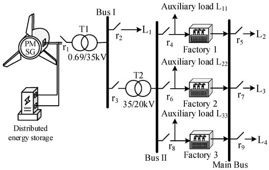
Figure 7.
Wiring Diagram of Black-Start Test Scheme for Grid-Forming Wind-Storage System.
Once the system stabilizes, power supply restoration for Factory 1 is achieved via Transformer T2 and Bus 2, with the factory’s auxiliary load L11 connected simultaneously. After Factory 1 operates normally and stably, the line load L2 is connected. The black-start restoration procedures for Factory 2 and Factory 3 are consistent with those for Factory 1. Through these steps, the power supply of the main bus is restored incrementally, and finally, the overall power supply restoration of the regional power grid is realized, marking the successful completion of the black start.
4.3. Black-Start Process Flow of Grid-Forming Wind-Storage System
The black-start control scheme of the grid-connected wind-storage system used in this study is shown in Figure 8. The detailed process of self-starting and load recovery of the wind-storage system, combined with multi-mode switching, is as follows:
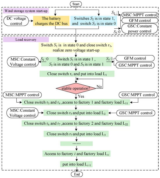
Figure 8.
Flow chart of black-start control scheme for Grid-Forming Wind-Storage System.
- (1)
- Self-Startup Method of the Wind-Storage System
First, the distributed energy storage system relies on its own capacity to charge the DC bus through a bidirectional DC–DC converter, maintaining the DC bus voltage at a constant level to enable the self-startup of PMSG. During this phase, the switches in the control system are set to specific states: Switch S2 is in State 1, and Switch S3 is in State 0. Specifically, the GSC adopts constant power control to reduce the output of active power, while the MSC adopts MPPT control. This control combination not only prevents excessive power absorption by the energy storage system but also ensures the rapid completion of the PMSG self-startup.
Since the system is in the no-load startup phase, Switch S1 is switched to State 0 to implement the zero-voltage startup strategy when connecting the main transformer. This strategy effectively suppresses the magnetizing inrush current generated by the no-load switching of the transformer, which is conducive to the rapid and smooth establishment of AC bus voltage and frequency under the grid-forming control strategy.
- (2)
- Load recovery
After the wind turbine reaches a stable operating state, the control configuration of the system is adjusted accordingly: Switch S2 is toggled to State 0, and Switch S3 to State 1. In this mode, the machine-side converter operates under constant DC voltage control, while the grid-side converter adopts MPPT control to satisfy the power demands of various loads during the subsequent restoration phase.
The load recovery sequence is switched according to the r1–r9 numbering sequence in Figure 7. According to actual operational needs, Knife Switch r2 is closed to restore the partial line load L1 of the system, thereby verifying the supporting effect of the grid-forming PMSG as a black-start power source. After the power supply for load L1 is restored, Knife Switches r3 to r9 are closed incrementally to simulate the step-by-step restoration of line loads, medium- and large-sized factories (primarily powered by synchronous generators), and their auxiliary loads in a practical regional power grid.
During the restoration of medium- and large-scale industrial loads, Switch S2 is switched to State 1, activating the MPPT control of the MSC to ensure adequate power output for high-demand conditions. Conversely, for the restoration of distribution lines or small-scale loads, Switch S2 remains in State 0, and constant DC voltage control is maintained, which is sufficient to support the lower power requirements of these units.
In this study, the rated capacities of the wind turbine and energy storage system are configured to satisfy the total load demand during the restoration process. This design prevents secondary transient faults or overload events that could otherwise arise from prolonged overcapacity operation, thereby ensuring a reliable and stable black-start restoration of the regional grid.
5. Controller-Level Hardware-in-the-Loop Experimental Results
5.1. Hardware-in-the-Loop Experimental Platform
To verify the feasibility of the proposed black-start control strategy and scheme for the grid-forming wind-storage system, a hardware-in-the-loop (HIL) test platform was constructed using experimental devices including an RT-LAB (OP5600, Montreal, QC, Canada) real-time simulator, a host computer, a waveform recorder, and an actual digital signal processor (DSP) controller. Real-time simulation verification was conducted on this platform, as illustrated in Figure 9.
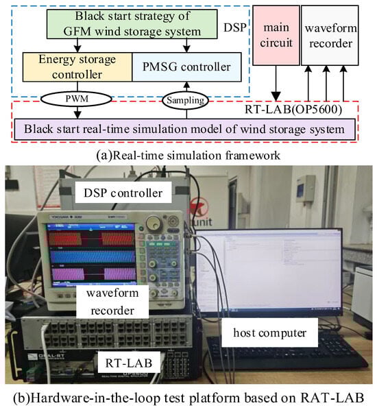
Figure 9.
Real-time simulation experiment platform of grid-forming PMSG controller. (a) Real-time simulation framework, (b) Hardware-in-the-loop test platform based on RT-LAB.
A simulation model of the grid-forming wind-storage system black start, which has a consistent structure with the topology shown in Figure 7, was built in the Simulink simulation environment. Subsequently, the simulation model was transferred from the host computer to the RT-LAB real-time simulator to enable real-time operation of the black-start main circuit simulation.
Figure 9a presents the real-time simulation framework based on RT-LAB. The black-start control strategy for the grid-forming wind-storage system was implemented in DSP controller. The RT-LAB real-time simulator was utilized to simulate the main circuit model of the black-start process: sampled signals such as voltage and current were transmitted to the DSP controller via Analog Output (AO) interfaces, while pulse-width modulation (PWM) control signals were sent to the RT-LAB simulator after level conversion to realize the control of converters. This platform simulated the entire process of a real wind-storage system, from self-startup to load restoration, enabling real-time monitoring of transient issues such as magnetizing inrush current during black start and transient phenomena occurring in the load restoration phase. Finally, a DL850 waveform recorder was used to collect measured data points, based on which variation curves of observed quantities were plotted for subsequent analysis.
The wind turbine adopted in this study is a PMSG with a rated capacity of 1.1 MW, a rated voltage of 690 V, and a pole pair number of 38. A single wind turbine is insufficient to support the black-start process; therefore, to simulate the actual black-start scenario, a multiplication module was used to scale up the rated capacity of the single wind turbine proportionally to 330 MW, so as to replicate the effect of a real wind farm serving as a black-start power source. The rated capacity of the energy storage system is 2 MW, and the initial SCO is 50%. The distributed energy storage is connected in parallel to the DC side of the PMSG through a bidirectional DC–DC converter. Its function is mainly used to stabilize the DC side voltage. The DC bus voltage is stabilized at a rated voltage of 1200 V by constant DC voltage control. The support capacity of the energy storage can be judged by the change in the DC bus voltage.
The main control and line parameters are summarized in Table 1, where all values are referred to the low-voltage side.

Table 1.
The parameters of system.
5.2. Simulation Validation of Magnetizing Inrush Current Suppression Strategy
Since the magnetizing inrush current phenomenon mainly occurs in the phase of switching on the unloaded transformer at the initial stage of black start, the simulation startup time was first set to 1.8 s, and the system was in a fully black state at the initial moment.
At t = 0.3 s, the distributed energy storage system cooperated with the grid-forming wind turbine to start as the black-start power source, and the unloaded transformer was switched on at the same time. The segmented zero-voltage startup module was introduced into the VSG control to gradually carry out the startup of the initial stage.
The output voltage and current waveforms of the grid-forming wind-storage system were observed before and after the introduction of the zero-voltage startup module.
As shown in Figure 10a,b, without the zero-voltage-start module, the grid-forming converter output voltage exhibits a step response. The rapid voltage buildup leads to transformer core saturation and a pronounced magnetizing inrush current, which destabilizes the system and may cause black-start failure.
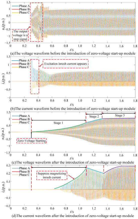
Figure 10.
Voltage and Current Waveforms Before and After Introducing the Zero-Voltage Startup Module.
As can be seen from Figure 10c,d, introducing the zero-voltage startup module into the VSG control can effectively suppress the magnetizing inrush current and successfully achieve segmented zero-voltage startup and voltage boosting. Specifically, at t = 0.3 s, the wind-storage system starts self-startup and switches on the unloaded transformer. In the first stage, the voltage rises to 80% of the rated voltage following an exponential function; in the second stage, it rises slowly to the rated voltage via a ramp function. During this period, the current is significantly suppressed under the grid-forming control. In the third stage, Switch S1 is toggled to State 1, and the system voltage required for the black start of the wind-storage system is gradually established and maintained stably. As a result, the magnetizing inrush current generated by switching on the unloaded transformer is significantly suppressed.
5.3. Simulation Validation of the Black-Start Scheme for the Grid-Forming Wind-Storage System
After the wind-storage system, serving as the black-start power source, achieved zero-voltage self-startup and maintained stable power output, line load restoration was carried out step-by-step in accordance with the black-start wiring diagram shown in Figure 7. During the black-start process, the PMSG dual-side converter multi-mode switching control strategy proposed in this paper was adopted. The output of key parameters during the black-start process was observed, and a comparison was made with the black-start effect under the traditional grid-forming VSG control to verify the feasibility of the improved black-start transient control strategy proposed in this paper.
A constant wind speed of 10 m/s was set. When t = 4 s, the PMSG switch S2 is switched to state 0, the switch S3 is switched to state 1, and the 40 MW initial load is connected. The load recovery effect is used to preliminarily verify whether the self-starting of the wind-storage system is successful. When t = 7 s, the switch S2 switches to State 1; when t = 7.5 s, the Factory 1 with a rated capacity of 30 MW and its 10 MW auxiliary load are connected. During the whole load recovery process, in order to meet the load recovery power demand, the PMSG grid-side converter always adopts MPPT control, while the control mode of the machine-side converter is switched by the switch S2 according to the load type. Then, the control mode is switched in turn at t = 12 s, 15 s, 20 s, 25 s, and 30 s. At the same time, according to the switch number in Figure 7, 30 MW basic load L2, rated capacity of 40 MW, Factory 2 and its 15 MW plant load, 30 MW basic load L3, 50 MW, Factory 3 and 15 MW plant load and 30 MW basic load L4 are put into operation in turn, and finally, the whole black-start process is realized.
By comparing Figure 11a,b, it can be seen that regarding the three-phase voltage output by the wind-storage system throughout the black-start process, after optimizing the control structure with the improved grid-forming black-start strategy, the switching overvoltage level during the first switching of medium-to-large factory loads is significantly reduced by 0.81 p.u. The waveform quickly returns to stability, reducing the transient impact on transformers and other equipment on the line, which is conducive to suppressing the transient impact at the moment of switching different types of loads during the black-start process.
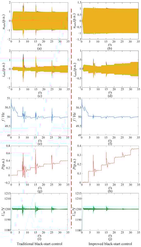
Figure 11.
Comparison of Simulation Waveforms Between Traditional Black-Start and Improved Black-Start Control Strategies.
Comparing Figure 11c,d, the transient overcurrent of the three-phase current during the black-start process is significantly suppressed. The transient fluctuation during the first switching is greatly reduced from 1.63 p.u. to 0.61 p.u., and the transient fluctuations caused by subsequent load switching are also significantly reduced. Combined with the voltage and current waveforms, the effectiveness of the improved grid-forming wind-storage system black-start strategy proposed in this paper is further verified.
From Figure 11e,f, it can be seen that the improved grid-forming black-start strategy has good frequency support capability in both the self-startup and load restoration phases of the wind-storage system, effectively reducing the maximum deviation of frequency variation. During the load restoration phase, the frequency variation does not exceed ±0.1 Hz, suppressing transient frequency drops, which verifies that the strategy effectively optimizes the frequency response characteristics of the system.
Figure 11g,h show the active power variation waveforms of the system during black start. Under the optimization of the improved strategy, the system active power suppresses power drops, with the over-limit reduced by 0.4 p.u. When connecting medium-to-large factory loads at 7.5 s, 15 s, and 25 s, the machine-side converter control is switched to MPPT control, and its active power output increases significantly to maintain the system’s power balance and meet the black-start power demands of different types of loads. When restoring basic loads, constant power control is adopted, and the power output meets the load demands.
Figure 11i,j show the DC bus voltage waveforms. Since the distributed energy storage system is connected in parallel with the PMSG on the DC bus, the energy storage system can quickly stabilize the DC bus voltage at 1200 V. Both figures show that the DC bus voltage remains stable throughout the black-start process, but the anti-interference capability of the DC bus under the improved black-start strategy is improved to a certain extent, and it can quickly return to the steady-state value after being disturbed.
Compared with predictive control methods, such as model predictive control (MPC) strategy [26], accurate current prediction and dynamic optimization of voltage trajectory can be achieved. However, these methods usually require a large amount of computation, accurate system parameter identification, and fast real-time solvers, which may limit their application in large-scale or distributed black-start systems. In contrast, the piecewise zero-voltage startup strategy proposed in this study provides a simple and control-oriented solution that can be easily embedded into the traditional VSG framework without additional hardware or computational burden.
In summary, compared with the traditional VSG control, the improved black-start strategy of grid-connected wind-storage systems using zero-voltage startup to suppress inrush current and multi-mode switching control of PMSG bilateral converter is verified. In the whole black-start process, the transient problems such as transient switching overvoltage, transient overcurrent, frequency drop, and power fluctuation are effectively suppressed. Therefore, the feasibility of the improved black-start strategy of the grid-connected wind-storage system proposed in this paper and the multi-stage efficient recovery in black-start are proposed. The simulation results of core parameters are shown in Table 2.
Table 2.
Comparison of Switching Load Effects Between Traditional and Improved Grid-Forming Black-Start Controls.
6. Conclusions
Based on the black-start control requirements of grid-forming wind-storage systems, this paper proposes and verifies an enhanced black-start control strategy that effectively balances transient stability, power coordination, and control adaptability under small-capacity distributed energy storage conditions. The work makes several innovative contributions to the control and implementation of grid-forming systems for renewable-based black start:
- (1)
- A novel segmented zero-voltage startup module is integrated into the VSG control outer loop to address the challenge of magnetizing inrush current during transformer energization. This design enables smooth and controlled voltage boosting during the early black-start phase. Simulation results demonstrate that this method reduces the magnetizing inrush current peak from 1.4–1.9 p.u. to 1.0–1.1 p.u., while extending the voltage rise time by approximately 60%. The strategy effectively prevents core saturation and transient overcurrent, ensuring significantly improved voltage stability and converter safety compared with traditional VSG control.
- (2)
- To enhance load restoration performance under constrained energy storage, a multi-mode switching control framework for the PMSG dual-side converter is developed. This framework realizes automatic switching between MPPT and constant-power/constant-voltage modes based on load type and system operating state. The coordinated control of machine-side and grid-side converters maintains frequency and power balance with limited storage capacity. Simulation verification confirms that the proposed strategy limits frequency deviation within ±0.1 Hz and reduces average power fluctuation by about 40%, achieving stable black start and load restoration with small-capacity distributed storage.
- (3)
- Through hardware-in-the-loop experiments using an RT-LAB real-time simulator and DSP controller, the feasibility and superiority of the proposed strategy are comprehensively validated. Results show that the method suppresses switching overvoltage and transient overcurrent, enhances system frequency support and power dynamic response, and demonstrates strong engineering applicability for practical black-start scenarios. Due to the limited conditions, it is impossible to carry out more accurate entity verification tests. In the follow-up study, the application scenarios will be broadened as much as possible to improve the verification accuracy.
Author Contributions
Conceptualization and methodology, T.Z.; Data curation, Y.W.; Formal analysis, J.M.; Software, D.C.; Validation, X.C.; Writing—original draft, Y.H.; Writing–review and editing, Y.D. All authors have read and agreed to the published version of the manuscript.
Funding
This research was funded by the Science and Technology Project of State Grid Beijing Electric Power Company under Grant 52022324000C.
Data Availability Statement
Data are contained within the article.
Conflicts of Interest
Author Tieheng Zhang was employed by the State Grid Beijing Electric Power Company. Authors Yucheng Hou, Yifeng Ding, Yi Wan and Xin Cao were employed by the company State Grid Beijing Electric Power Research Institute. The remaining authors declare that the research was conducted in the absence of any commercial or financial relationships that could be construed as a potential conflict of interest.
References
- Zhang, Z.; Sun, D.; Zhao, C.; Nian, H. An Improved Grid-Forming Control Strategy of Wind Turbine Generators with the Supercapacitor for Optimizing Primary Frequency Regulation Ability. IEEE Trans. Energy Convers. 2025, 40, 306–322. [Google Scholar] [CrossRef]
- Raza, M.W.; Badia, J.G.; Prieto-Araujo, E.; Gomis-Bellmunt, O. Fault Handling Capabilities of Grid-Forming Wind Turbines in Offshore Wind Farms Connected with MMC HVDC System. IEEE Access 2024, 12, 36404–36414. [Google Scholar] [CrossRef]
- Arasteh, A.; Zeni, L.; Cutululis, N.A. Fault ride through capability of grid forming wind turbines: A comparison of three control schemes. IET Renew. Power Gener. 2022, 16, 1866–1881. [Google Scholar] [CrossRef]
- Wang, P.; Ma, J.; Zhang, R.; Wang, S.; Liu, T.; Yang, Y. Stability Criterion for Near-Area Grid-Forming Converters Under the Weak Grid Condition. IEEE Trans. Power Electron. 2025, 40, 361–374. [Google Scholar] [CrossRef]
- Qin, Y.; Wang, H.; Deng, Z.; Zhang, J.; Yang, R.; Cai, X. Control of inertia-synchronization controlled wind turbine generators under symmetrical grid faults. IEEE Trans. Energy Convers. 2023, 38, 1085–1096. [Google Scholar] [CrossRef]
- Chen, S.; Sun, Y.; Hou, X.; Han, H.; Fu, S.; Su, M. Quantitative parameters design of VSG oriented to transient synchronization stability. IEEE Trans. Power Syst. 2023, 38, 4978–4981. [Google Scholar] [CrossRef]
- Liu, W.; Liu, Y. Hierarchical model predictive control of wind farm with an energy storage system for frequency regulation during black-start. Int. J. Electr. Power Energy Syst. 2020, 119, 105893. [Google Scholar] [CrossRef]
- Fan, J.; Niu, L.; Li, C.; Zhang, G.; Li, H.; Wang, Y.; Li, J.; Song, Q.; Sun, J.; Pan, J.; et al. Review of Black Start on New Power System Based on Energy Storage Technology. Energy Eng. 2023, 120, 2857–2878. [Google Scholar] [CrossRef]
- Xiaodong, Y.; Kunpeng, Z.; Defu, C.; Rusi, C.; Kan, C.; Yunfeng, L. Analysis of Excitation Inrush Current and Secondary Harmonic during 500kV AC Field Commissioning Test of ±800kV Shan to Wu UHVDC. In Proceedings of the 2022 4th Asia Energy and Electrical Engineering Symposium (AEEES), Online, 25–28 March 2022; pp. 529–535. [Google Scholar]
- Mishra, P.; Swain, A.; Pradhan, A.K.; Bajpai, P. Sequence Current-Based Inrush Detection in High-Permeability Core Transformers. IEEE Trans. Instrum. Meas. 2023, 72, 3534509. [Google Scholar] [CrossRef]
- Shu, H.; Jiang, X.; Bo, Z. Identifying inrush current for large-scale wind parks transformers based on difference function of differential current. IEEE Trans. Power Deliv. 2023, 38, 1768–1779. [Google Scholar] [CrossRef]
- Aghazadeh, A.; Hajipour, E.; Li, K.; Azizi, S. Mitigating the Inrush Current of v/v Transformers Using Railway Conditioners. IEEE Access 2024, 12, 50885–50897. [Google Scholar] [CrossRef]
- Wang, Q.; Zhu, M.; Ding, T.; Gao, M.; Jiao, Y. Research on Inrush Current Suppression of No-load Transformer Closing Based on Circuit Breaker Action Time Prediction. In Proceedings of the 2024 21st International Conference on Harmonics and Quality of Power (ICHQP), Chengdu, China, 15–18 October 2024; IEEE: New York, NY, USA, 2024. [Google Scholar]
- Han, P.; Tong, Q.; Wang, Y.; Chen, Z.; Yang, W.; Hu, D.; Wu, H.; Zhang, J. An Inrush Current Suppression Strategy for UHV Converter Transformer Based on Simulation of Magnetic Bias. Trans. Power Deliv. 2022, 37, 5179–5189. [Google Scholar] [CrossRef]
- Sanati, S.; Ahmadi, S.; Sanaye Pasand, M. An innovative harmonic-based approach for inrush current detection in low-loss transformers. IET Gener. Transm. Distrib. 2024, 18, 1303–1316. [Google Scholar] [CrossRef]
- Kadri, R.; Gaubert, J.-P. An improved maximum power point tracking for photovoltaic grid connected inverter based on voltage oriented control. IEEE Trans. Ind. Electron. 2011, 58, 66–75. [Google Scholar] [CrossRef]
- Yan, W.; Gevorgian, V.; Koralewicz, P.; Alam, S.M.S.; Mendiola, E. Regional power system black start with run-of-river hydropower plant and battery energy storage. J. Mod. Power Syst. Clean Energy 2024, 12, 1596–1604. [Google Scholar] [CrossRef]
- Asensio, A.P.; Gómez, S.A.; Rodriguez-Amenedo, J.L. Black-start capability of PV power plants through a grid-forming control based on reactive power synchronization. Int. J. Electr. Power Energy Syst. 2023, 146, 108730. [Google Scholar] [CrossRef]
- Shahparasti, M.; Laaksonen, H.; Kauhaniemi, K.; Lauttamus, P.; Strandberg, S.; Strandberg, J. Inrush Current Management During Medium Voltage Microgrid Black Start with Battery Energy Storage System. IEEE Access 2022, 10, 42287–42296. [Google Scholar] [CrossRef]
- Rodriguez-Amenedo, J.L.; Gomez, S.A.; Martinez, J.C.; Alonso-Martinez, J. Black-Start Capability of DFIG Wind Turbines Through a Grid-Forming Control Based on the Rotor Flux Orientation. IEEE Access 2021, 9, 142910–142924. [Google Scholar] [CrossRef]
- Kong, F.; Li, J.; Liao, M.; Li, S.; Lin, X.; Ding, X. Research on Transformer Saturation Mechanism and Restraining Measures in VSC-HVDC Black Start Process. In Proceedings of the 2022 12th International Conference on Power and Energy Systems (ICPES), Guangzhou, China, 23–25 December 2022; IEEE: New York, NY, USA, 2022; pp. 267–270. [Google Scholar]
- Sun, L.; Lin, Z.; Xu, Y.; Wen, F.; Zhang, C.; Xue, Y. Optimal skeleton-network restoration considering generator start-up sequence and load pickup. IEEE Trans. Smart Grid 2019, 10, 3174–3185. [Google Scholar] [CrossRef]
- Li, J.; You, H.; Qi, J.; Kong, M.; Zhang, S.; Zhang, H. Stratified Optimization Strategy Used for Restoration with Photovoltaic-Battery Energy Storage Systems as Black-Start Resources. IEEE Access 2019, 7, 127339–127352. [Google Scholar] [CrossRef]
- Li, C.; Zhang, S.; Li, J.; Zhang, H.; You, H.; Qi, J.; Li, J. Coordinated Control Strategy of Multiple Energy Storage Power Stations Supporting Black-Start Based on Dynamic Allocation. J. Energy Storage 2020, 31, 101683. [Google Scholar] [CrossRef]
- Dang, P.; Jia, R.; Pan, Z.; Cao, G.; Guo, Z. Black-start Control Strategy of the Wind-storage Combined Power System under Isolated Island Condition. In Proceedings of the 2023 International Conference on Power Energy Systems and Applications (ICoPESA), Nanjing, China, 24–26 February 2023; IEEE: New York, NY, USA, 2023; pp. 407–412. [Google Scholar]
- Redmann, F.; Ernst, A.; Orlik, B. Black start capability and islanded operation of power converters with virtual synchronous generator control. In Proceedings of the International Exhibition and Conference for Power Electronics, Shenzhen, China, 9–11 September 2021; IEEE: New York, NY, USA, 2021; pp. 1–8. [Google Scholar]
- Weipeng, L.; Yutian, L.; Lei, W. Model Predictive Control Based Voltage Regulation Strategy Using Wind Farm as Black-Start Source. IEEE Trans. Sustain. Energy 2023, 14, 1122–1134. [Google Scholar] [CrossRef]
- Daniela, P.; Lukasz, K.; Jesper, H.; Frede, B.; Claus Leth, B. Integrating Black Start Capabilities into Offshore Wind Farms by Grid-Forming Batteries. IET Renew. Power Gener. 2023, 17, 3523–3535. [Google Scholar]
- Binxiang, X.; Jie, R.; Zixuan, Z.; Wenxi, H.; Qi, X.; Donghui, S. Suppressing the Post-Fault Overvoltage with Cooperative Reactive Power Control for SMES Integrated PMSG-Based Wind Turbine. IEEE Trans. Appl. Supercond. 2024, 34, 5701906. [Google Scholar]
- Seyedmahdi, I.; Rafael, C.; Pablo, F.; Pablo, G.; Andrea, R. Performance Evaluation of a BESS Unit for Black Start and Seamless Islanding Operation. Energies 2022, 15, 1736. [Google Scholar] [CrossRef]
- MMohammed, A.; Petr, M. Reinforcement Learning-Based Distributed BESS Management for Mitigating Overvoltage Issues in Systems with High PV Penetration. IEEE Trans. Smart Grid 2020, 11, 2980–2994. [Google Scholar] [CrossRef]
Disclaimer/Publisher’s Note: The statements, opinions and data contained in all publications are solely those of the individual author(s) and contributor(s) and not of MDPI and/or the editor(s). MDPI and/or the editor(s) disclaim responsibility for any injury to people or property resulting from any ideas, methods, instructions or products referred to in the content. |
© 2025 by the authors. Licensee MDPI, Basel, Switzerland. This article is an open access article distributed under the terms and conditions of the Creative Commons Attribution (CC BY) license (https://creativecommons.org/licenses/by/4.0/).