Article

Research on Pole-to-Ground Fault Ride-Through Strategy for Hybrid Half-Wave Alternating MMC

by
Yanru Ding
1,
Yi Wang
1,*,
Yuhua Gao
1,
Zimeng Su
1,
Xiaoyu Song
1,
Xiaoyin Wu
1 and
Yilei Gu
2
1
College of Electrical Engineering, North China Electric Power University, Baoding 071003, China
2
State Grid Zhejiang Electrical Power Co., Ltd., Hangzhou 310000, China
*
Author to whom correspondence should be addressed.
Electronics 2025, 14(14), 2893; https://doi.org/10.3390/electronics14142893 (registering DOI)
Submission received: 19 June 2025 / Revised: 16 July 2025 / Accepted: 18 July 2025 / Published: 19 July 2025

Abstract

Considering the lightweight requirement of modular multilevel converter (MMC), the implementation of arm multiplexing significantly improves submodule utilization and achieves remarkable lightweight performance. However, the challenges of overvoltage and energy imbalance during pole-to-ground fault still exist. To address these issues, this paper proposes a hybrid half-wave alternating MMC (HHA-MMC) and presents its fault ride-through strategy. First, a transient equivalent model based on topology and operation principles is established to analyze fault characteristics. Depending on the arm’s alternative multiplexing feature, the half-wave shift non-blocking fault ride-through strategy is proposed to eliminate system overvoltage and fault current. Furthermore, to eliminate energy imbalance caused by asymmetric operation during non-blocking transients, dual-modulation energy balancing control based on the third-harmonic current and the phase-shifted angle is introduced. This strategy ensures capacitor voltage balance while maintaining 50% rated power transmission during the fault period. Finally, simulations and experiments demonstrate that the lightweight HHA-MMC successfully accomplishes non-blocking pole-to-ground fault ride-through with balanced arm energy distribution, effectively enhancing power supply reliability.

1. Introduction

Against the background of continuously increasing renewable energy penetration and rapidly growing power load demand, the capacity expansion and voltage elevation of medium-voltage direct-current (MVDC) and high-voltage direct-current (HVDC) transmission systems have become increasingly urgent [1,2]. The modular multilevel converter (MMC) has emerged as the dominant topology in these fields owing to its merits of low harmonics, high modularity, and excellent scalability [3,4,5]. However, its large number of submodules requires extensive semiconductor devices and capacitors, resulting in significant weight and volume challenges. This drawback is particularly pronounced in space-constrained applications such as offshore wind farms and urban medium-voltage distribution networks [6,7]. Additionally, existing MMCs based on half-bridge submodules (HBSMs) cannot handle DC faults and require submodules with more devices for reliable fault protection [8,9]. Above all, it is necessary to comprehensively consider the lightweight design of the MMC and its DC fault ride-through capability, especially for the most common scenario of pole-to-ground fault [10].
Currently, studies on lightweight MMCs primarily focus on two approaches: capacitance reduction control and revised topologies. Due to high power transmission constraints, the capacitance reduction control strategy that reduces capacitor voltage ripple has limited effectiveness [11]. Consequently, reducing capacitor usage through revised topologies has become the more viable solution. Among them, Hybrid Multilevel Converters (HMCs) are constructed by cascading switch devices with submodules. These topologies combine the advantages of both two-level converters and the MMC, achieving remarkable lightweight performance [12,13,14,15,16,17]. The Alternate Arm Multilevel Converter (AAMC) was introduced in [13], which uses alternative switches to control the alternating conduction between the upper and lower arms, thereby reducing the number of submodules required. But it can only operate stably within a fixed modulation ratio. The Hybrid Arm Multiplexing MMC (HAM-MMC) was proposed in [14], which employs AC-side arm selection switches to achieve time-division multiplexing of arms, significantly improving submodule utilization efficiency. To further reduce the number of submodules, reference [15] combined the concepts of the above two topologies to propose the half-wave alternating MMC (HA-MMC). This topology achieves full-time multiplexing of arms, significantly reducing the number of required submodules by at least 59%. Current studies demonstrate that the HA-MMC can efficiently convert AC/DC voltage and transmit power while maintaining certain DC fault tolerance. Moreover, it does not require arm inductors and completely avoids inter-phase circulating currents, significantly reducing both the physical size and cost of converter stations [16,17]. However, such multiplexed MMC topology still faces challenges in energy balancing, and the energy mechanism becomes even more complex during fault ride-through conditions.
Pole-to-ground fault, the most common DC-side fault, has traditionally been addressed through DC circuit breakers (DCCBs), surge arrester configurations, and converter blocking [18,19,20]. However, these conventional solutions often lead to multiple issues, including high costs, difficult fault identification, capacitor voltage imbalance, and power transmission interruptions. While non-blocking fault ride-through strategies utilizing the negative voltage output capability of full-bridge submodules (FBSMs) can maintain continuous power supply and reduce equipment stress, it has emerged as a research focus. Notably, the hybrid full-bridge/half-bridge MMC (HF-MMC), which combines DC fault ride-through capability with reduced construction costs, has been successfully implemented in major projects such as the Kunliulong HVDC project [21,22]. However, as an asymmetric fault, pole-to-ground fault creates an inherent energy imbalance despite overvoltage elimination through faulty pole voltage adjustment, which severely compromises converter operation. Many balancing control methods have been proposed to solve this issue. In [23], arm balancing was achieved by introducing an offset phase angle between the upper- and lower-arm reference voltages to alter the arm currents. In [24], a fundamental frequency reactive circulating current was injected to enable the bidirectional flow of faulty pole currents, and the output voltages of the submodules were regulated to achieve fast charging of the HBSM, thereby balancing the converter power. And in [25], two DC modulation indices and four AC modulation indices were introduced to achieve independent control of the upper and lower bridge arms. However, the above common strategies all employ closed-loop control, making them complex, and they exhibit relatively slow response speeds. In addition, owing to the unique topology and absence of inter-phase circulating currents, the full-time arm multiplexed MMC exhibits different pole-to-ground fault characteristics compared to the conventional MMC, and further research is needed.
To address the above dual challenges, a hybrid half-wave alternating MMC (HHA-MMC) is designed, which simultaneously optimizes economic efficiency and fault tolerance, and the pole-to-ground fault characteristics and fault ride-through strategies are presented. First, the operation principle of the HHA-MMC is presented. Subsequently, the pole-to-ground fault transient characteristics are analyzed, with analytical expressions for fault voltages/currents derived. Then, the half-wave shift non-blocking control strategy is proposed to eliminate system overvoltage and fault current, accompanied with design guidelines for FBSM configuration. Furthermore, to resolve energy imbalance during asymmetric operation, the dual-modulation control strategy coordinating the third-harmonic current and the phase-shifted angle is proposed. Finally, the effectiveness of the proposed strategies is validated using Matlab/Simulink R2022b and HIL experiments.

2. Topology and Operation Principle of HHA-MMC

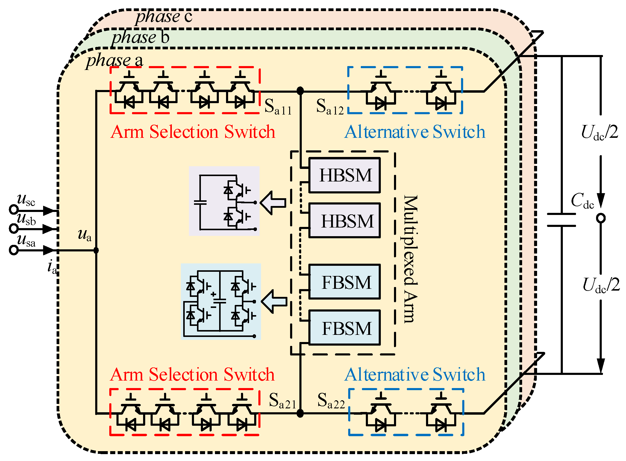
2.1. Topology Description

As shown in Figure 1, the HHA-MMC topology consists of three identical parallel phase units, each comprising the shaping circuit, the arm selection switches, and the alternative switches. Specifically, the AC output terminal is connected to the junction point of two adjacent arms via arm selection switches composed of multiple reverse-series IGBTs. The shaping circuit employs hybrid full-bridge and half-bridge submodules in series to generate a stepped waveform. The alternative switches on the arms are formed by series-connected IGBTs, controlling the conduction of the upper and lower arms. Compared to the conventional MMC, the number of submodules in this topology can be reduced to at least 0.82N [14], achieving a 59% reduction in submodule capacitors.

2.2. Operation Principle

Within one power frequency cycle (50 Hz), the AC-side arm selection switches and the upper/lower-arm alternative switches of HHA-MMC sequentially connect with the multiplexed arm to form two operational modes: the upper-arm multiplexing mode and the lower-arm multiplexing mode. By coordinating the switching operations between the upper/lower-arm alternative switches and the AC-side arm selection switches, the phase unit alternates between these operating modes at twice the power frequency. This enables bidirectional power conversion between the AC and DC terminals of the converter.
Using phase j (j = a, b, c, as in the following) as an example, Figure 2 illustrates the operation principle of the HHA-MMC. The arm selection switch Sj21 and alternative switch Sj12 are configured as the equivalent upper-arm switching group Kjp, while the arm selection switch Sj11 and alternative switch Sj22 form the equivalent lower-arm switching group Kjn. During the positive half-cycle of the reference voltage, Kjp is open with Kjn closed, initiating the upper-arm multiplexing mode. Conversely, during the negative half-cycle, Kjp is closed while Kjn is open, transitioning phase j to the lower-arm multiplexing mode. The periodic alternation between these two switching groups achieves half-wave inversion, ultimately constructing a complete sine wave at the output.
Assuming the valve-side AC voltage contains no harmonic components, the voltage and current expressions for phase j can be defined as
u j ( t ) = U m sin ( ω t + φ j ) i j ( t ) = I m sin ( ω t + φ j φ )
where Um and Im are the amplitude of the phase voltage and current, respectively. φj represents the initial phase angle of phase j, and φ denotes the power factor angle.
Let Sj be the switching function that defines the operational mode of the phase j unit:
S j = 1 , 0 < ω t < π   K jp open ,   K jn closed 0 , π < ω t < 2 π   K jn open ,   K jp closed
Based on Kirchhoff’s Voltage Law (KVL), the equivalent voltage umj and current imj for phase j can be derived as follows:
u mj = U dc 2 ( 1 m sin ( ω t + φ j ) ) ,   S j = 1 U dc 2 ( 1 + m sin ( ω t + φ j ) ) ,   S j = 0 i mj = I m sin ( ω t + φ j φ ) ,   S j = 1 I m sin ( ω t + φ j φ ) ,   S j = 0

3. Analysis of Pole-to-Ground Fault Characteristics in HHA-MMC

Flexible DC systems based on the HHA-MMC typically employ a pseudo-bipolar configuration. To maintain DC pole symmetry, a grounding point must be established at the converter station to provide a zero-potential reference. However, DC-side grounding through clamping resistors introduces significant active power losses and thermal management challenges. Consequently, AC-side grounding schemes are predominantly used in practical engineering applications. Among these, the star-connected reactor grounding method can cause substantial voltage fluctuations and reactive power consumption during converter startup/shutdown, along with excessively high construction costs. Currently, the most prevalent AC-side grounding approach is converter transformer neutral-point resistance grounding, which has successfully been implemented in major projects such as the Guangdong Nanao three-terminal MMC-HVDC project [26]. Given the similar fault characteristics exhibited by these two AC-side grounding methods, this study mainly focuses on pole-to-ground fault behavior and fault ride-through control strategies for HHA-MMC systems under the transformer neutral-point resistance grounding scenario.
Taking a positive pole-to-ground DC short-circuit fault in the HHA-MMC as an example, when phases abc instantaneously operate in “upper–lower–upper” multiplexing mode at the fault occurrence. Figure 3 shows the conduction path of fault current if and the equivalent fault circuit. In this case, phase a and phase c arms operate in upper-arm multiplexing mode, where the capacitors of the inserted SMs discharge through the short-circuit point and system grounding point (shown by the red dashed line), similar to the conventional MMC. The phase b arm operates in lower-arm multiplexing mode, where the DC-side supporting capacitors discharge via the multiplexing arm, short-circuit point, and system grounding point (shown by the blue dashed line).
As shown in Figure 3b,c, the fault circuit can be equivalently modeled as a second-order RLC circuit with known initial conditions, where the equivalent inductance Leq equals the DC cable inductance Ldc, and the equivalent resistance Req is the sum of the DC line resistance Rdc, fault resistance Rf, and grounding resistance Rg. When the number of inserted SMs in the arm is Nref (corresponding to Nref series-connected capacitors), the submodule voltage balancing algorithm ensures normal switching operation. Consequently, the equivalent capacitance Ceq can be derived as Nref/N capacitors Cref connected in parallel. The detailed parameters are specified as follows:
R eq = R dc + R f + R g L eq = L dc C eq = C ref N N ref 2
Assuming a positive pole-to-ground fault occurs at time t0 with an initial discharge current If0, the equivalent circuit for phases a and c in the upper-arm multiplexing mode satisfies the following differential equations:
L eq d i fa _ up ( t ) d t + R eq i fa _ up ( t ) = u c ( t ) + u ao ( t )
u c t 0 + = u c t 0 U dc / 2 u ao ( 0 ) i fa _ up t 0 + = I f 0 = i arm t 0 u ao t = U m sin ( ω t + φ a )
For phase b operating in lower-arm multiplexing mode, the equivalent circuit satisfies the following differential equations:
L eq d i fb _ low ( t ) d t + R eq i fb _ low ( t ) + u c ( t ) = u dc ( t ) + u bo ( t )
u c t 0 + = u c t 0 U dc / 2 u bo ( 0 ) u dc t 0 + = u dc t 0 = U dc i fb _ low t 0 + = I f 0 = i arm t 0 u bo t = U m sin ( ω t + φ b )
where uC(t) is the voltage of Ceq, and Udc is the DC bus voltage. ifj_up and ifj_low are the fault currents during the upper- and lower-arm multiplexing periods of phase j, respectively. iarm is the instantaneous value of the arm current, and ω is the fundamental angular frequency.
Equations (5) and (7) show that unlike the conventional MMC, where pole-to-ground fault only generates fault currents in the faulty pole’s arms, the HHA-MMC’s unique single-arm full-time multiplexing topology generates fault currents in all phase arms when a pole-to-ground fault occurs regardless of whether the upper- or lower-arm multiplexing mode is activated. Following the three-phase multiplexing mode variation cycle, both positive and negative DC bus fault currents exhibit six-pulse characteristics. The total fault current is expressed as
i f = j = a , b , c S j i fj _ up + ( 1 S j ) · i fj _ low
The positive- and negative-pole voltages in the DC side are expressed as
U dcp = I f R f U dcn = U d c + I f R f
Applying Kirchhoff’s Voltage Law (KVL) to the fault current path yields the following AC valve-side voltage:
u vj ( t ) = U dcp u mj ( t ) , S j = 1 U dcn + u mj ( t ) , S j = 0
In summary, since practical grounding impedance is typically large (on the order of kΩ) [20], the fault currents derived from Equations (5) and (7) exhibit overdamped characteristics. Pole-to-ground faults thus have a negligible impact on system operation and do not require protective device activation. However, according to Equations (10) and (11), the healthy DC pole bus will experience a 2 times greater overvoltage, and the AC valve-side voltage and the neutral point of the converter transformer will develop a 0.5 times DC voltage offset. When using conventionally designed converter transformers, their dielectric strength becomes inadequate. Furthermore, persistent fault arcs in DC lines can generate sustained high-magnitude short-circuit currents, triggering AC-side protection and ultimately causing complete power transmission interruption.

4. Fault Ride-Through Strategy for PTG DC Fault in HHA-MMC

To achieve pole-to-ground fault ride-through for the HHA-MMC while maintaining submodule capacitor voltage balance, this section proposes a non-blocking ride-through strategy based on dual-modulation energy balancing control. This strategy must achieve two functions:
(1)
Rapid Overvoltage and Fault Current Elimination
By improving the reference waveform for the faulty pole’s half-cycle multiplexed arms, the strategy rapidly suppresses overvoltage and fault current without converter blocking, thereby preventing insulation threats to interconnected AC/DC systems.
(2)
Dynamic Energy Balancing
Modulating the third-harmonic current in conjunction with the phase-shifted angle dynamically balances the energy accumulation issues caused by isolating the pole-to-ground fault during the faulty pole multiplexing mode half-cycle. It enables the continuous transmission of 50% rated active power while providing reactive power support for the AC system.

4.1. Half-Wave Shift Non-Blocking Fault Ride-Through Mechanism

Due to the inherent alternating conduction characteristics of the HHA-MMC, this paper proposes a half-wave shift non-blocking control strategy. To eliminate both the DC-side severe overvoltage and the Udc/2 DC bias on the AC side, the negative voltage output capability of FBSMs needs to be utilized simply during the half-cycle of the upper-arm multiplexing mode, thereby reducing the output voltage by Udc/2. The arm reference voltage and current are expressed as
u mj = m U dc 2 sin ( ω t + φ j ) ,   S j = 1 U dc 2 ( 1 + m sin ( ω t + φ j ) ) ,   S j = 0 i mj = I m sin ( ω t + φ j φ ) ,   S j = 1 I m sin ( ω t + φ j φ ) ,   S j = 0
The modulation principle for reducing the equivalent arm voltage during the upper-arm multiplexed half-cycle is illustrated in Figure 4.
At this time, the positive-pole DC bus voltage collapses to zero immediately upon fault detection to extinguish the fault current. During the half-cycle of the upper-arm multiplexing mode, the HHA-MMC promptly switches to Static Synchronous Compensator (STATCOM) operation mode, while the negative-pole bus maintains its rated voltage in the lower-arm multiplexing half-cycle to sustain power transmission. Therefore, the reactive power transmission capability of the arms remains unaffected throughout the entire cycle, and the HHA-MMC can still deliver 50% of active power during the lower-arm multiplexing period. The reference value for power should be set to
Q = Q ref P = 1 2 P ref
However, under this control strategy, the active power output from the AC side still uniformly transmits throughout the entire cycle due to the alternating conduction characteristics of the upper and lower arms. Actually, in the improved multiplexing mode, only the lower-arm multiplexing half-cycle can exchange active power with the DC system. Consequently, the accumulated energy Δ E m in the arm over one cycle after mode improvement becomes
Δ E m = 1 ω 0 2 π u mj · i mj d ω t = Δ E mp + Δ E mn = 1 ω 0 π m U dc 2 sin ( ω t + φ j ) · I m sin ( ω t + φ j φ ) d ω t + 1 ω π 2 π U dc 2 ( 1 + m sin ( ω t + φ j ) ) · I m sin ( ω t + φ j φ ) d ω t = U dc I m 4 ω π m cos φ + U dc I m 2 ω ( π 2 m cos φ 2 cos φ )
Equation (14) shows that during the upper-arm multiplexing half-cycle, the AC side continuously transmits power, and Δ E mp remains positive, resulting in sustained energy accumulation in the arm, while during the lower-arm multiplexing half-cycle, Δ E mn remains at zero due to the modulation ratio constraint. Therefore, the arm energy cannot achieve full-cycle equilibrium, and the capacitor voltages will continuously rise, ultimately compromising the safe operation of converter switching devices. The capacitive voltage deviation Δucj in the phase j arm can be further expressed as
Δ E ( t ) = 1 ω t 0 t u mj · i mj d ω t = 1 2 N C ( u cj ( t 0 ) + Δ u cj ( t ) ) 2 1 2 N C u cj 2 ( t 0 )
Δ u cj ( t ) = m U dc I m cos φ ( t t 0 ) 8 ω N u cj ( t 0 )

4.2. Dual-Modulation Energy Balancing Mechanism

As analyzed in Section 4.1, the improved modulation wave employing the half-wave shift non-blocking control strategy effectively suppresses system overvoltage and fault currents. However, asymmetric operation between the faulty pole multiplexing half-cycle and healthy pole multiplexing half-cycle causes energy to accumulate in the converter arms, resulting in unequal energy absorption and release within one operational cycle and, ultimately, arm energy imbalance.
To ensure stable post-fault operation of the HA-MMC while maintaining 50% active power transmission during healthy pole multiplexing cycles, a novel energy balancing strategy must be implemented to achieve full-cycle energy equilibrium (Δ E m = 0). This requires each lower-arm multiplexing half-cycle to fully dissipate the accumulated active power from the improved upper-arm multiplexing half-cycle, thereby restricting all active power transmission exclusively to the lower-arm multiplexing mode.
The implementation is initiated by introducing the first modulation degree with an adjustable phase-shifted angle θ, corresponding to the zero-crossing phase delay of the reference voltage uj(t). The switching function Sj is modified as follows:
S j = 1 , θ < ω t < π + θ 0 , π + θ < ω t < 2 π + θ
Taking the normal operation mode as an example, the energy balance expression over one operational cycle is derived as follows:
Δ E m = 1 ω θ 2 π + θ u mj i mj d ( ω t ) = U dc I m 2 ω ( π m cos φ 4 cos ( θ φ ) ) = 0
Then, the following constraint condition can be derived:
θ = φ ± arccos ( π 4 m cos φ )
The maximum voltage across the multiplexed arm is
u m . max = U dc 2 ( 1 + m sin θ )
With the introduction of this modulation degree, the controllable range of the modulation ratio, m, can be extended to [0, 4/π]. Equations (19) and (20) reveal that the maximum value of um.max reaches 0.82Udc when m = 0.9 and φ = 0 or π, requiring each phase unit to be configured with 0.82N submodules.
When substituting Equation (15) into Equation (14), the phase-shifted angle constraint for satisfying the energy balance condition in the improved multiplexing mode becomes
θ = φ ± arccos ( π 2 m cos φ )
The adjustment of θ exhibits a margin limitation that must satisfy
1 π 2 m cos φ 1
The above derivation indicates that energy balance after pole-to-ground fault can be maintained solely through θ adjustment only when m ≤ 2/πcosφ′ ≤ 2/π. Although θ exhibits effective modulation performance under normal operating conditions, its adjustment margin becomes insufficient in the course of pole-to-ground fault. To overcome this energy balance limitation and restore θ’s controllability, it is necessary to introduce a second modulation degree by injecting the third-harmonic current into the converter arms based on the phase shift switching control, where the injected third-harmonic current and its induced voltage across the equivalent reactance are expressed as
i 3 mj ( t ) = I 3 m sin ( 3 ω t α ) u 3 mj ( t ) = U 3 m sin ( 3 ω t α + π 2 )
At this point, the voltage and current of the multiplexed arm are modified as follows:
u mj ( t ) = u mj ( t ) u 3 mj ( t ) ,   S j = 1 u mj ( t ) + u 3 mj ( t ) ,   S j = 0 i mj ( t ) = i mj ( t ) + i 3 mj ( t ) ,   S j = 1 i mj ( t ) i 3 mj ( t ) ,   S j = 0
Recalculating the accumulated energy during the half-cycle of the upper-arm multiplexing mode reveals that the energy comprises four components: ΔEmp11 represents the energy accumulated from the fundamental voltage and current interaction before the third-harmonic injection, ΔEmp13 represents the energy accumulated from the fundamental voltage and third-harmonic current interaction, ΔEmp31 represents the energy accumulated from the third-harmonic voltage and fundamental current interaction, and ΔEmp33 represents the energy accumulated from the third-harmonic voltage and current interaction.
Δ E mp = θ π + θ ω ( u mj ( t ) u 3 mj ( t ) ) · ( i mj ( t ) + i 3 mj ( t ) ) d ω t = θ π + θ ω u mj ( t ) i 3 mj ( t ) d t + θ π + θ ω u mj ( t ) i 3 mj ( t ) d t θ π + θ ω u 3 mj ( t ) i mj ( t ) d t θ π + θ ω u 3 mj ( t ) i mj ( t ) d t = Δ E mp 11 Δ E mp 13 + Δ E mp 31 Δ E mp 33
Δ E mp 11 = Δ E mp = U dc I m 2 ω π m cos φ Δ E mp 13 = θ π + θ ω m U dc I 3 m 4 cos ( 4 ω t + φ j α ) cos ( 2 ω t + φ j + α ) d t = 0 Δ E mp 31 = θ π + θ ω U 3 m I m 2 sin ( 2 ω t α φ j + φ ) + sin ( 4 ω t α + φ j φ ) d t = 0 Δ E mp 33 = θ π + θ ω 1 2 U 3 m I 3 m cos ( 6 ω t 2 α + π 2 ) d t = 0
Equation (26) reveals that introducing a third-harmonic voltage into the modulation wave does not cause any energy variation. Furthermore, since the improved upper-arm reference voltage contains no DC component, the injection of the third-harmonic current also induces no energy change during the improved upper-arm multiplexing half-cycle.
Similarly, the accumulated energy in the lower-arm multiplexing half-cycle under this operational regime is expressed as
Δ E mn = Δ E mn 11 Δ E mn 13 + Δ E mn 31 Δ E mn 33  
Δ E mn 11 = Δ E mn = U dc I m 4 ω ( π m cos φ cos ( θ φ ) ) Δ E mn 13 = θ π + θ ω ( 1 + sin ( ω t + φ j ) ) · sin ( 3 ω t α ) d t = U dc I 3 m 3 ω cos ( 3 θ α ) Δ E mn 31 = 0 Δ E mn 33 = 0
In contrast to the improved upper-arm multiplexing mode, the lower-arm multiplexing mode retains a DC component in its arm reference voltage. Consequently, the introduction of third-harmonic current components induces energy fluctuations within this half-cycle. The product of these fluctuations and the DC component in the lower-arm reference voltage can be utilized to either dissipate or compensate for arm energy imbalance, thereby establishing a new modulation degree that further expands the energy balance regulation range.
Define μ as the ratio of the injected third-harmonic current amplitude to the fundamental current amplitude in the multiplexed arm:
μ = I 3 m I m
Based on the preceding derivation, after implementing both the phase-shifted angle and the third-harmonic current, the energy variation in the multiplexed arm over a complete operational cycle is expressed as
Δ E m = U dc I m 2 ω ( m π cos φ 2 cos ( θ φ ) ) + 2 μ 3 cos ( 3 θ α )
Therefore, when Δ E m = 0,
θ = φ ± arccos ( m 2 π cos φ + 1 3 μ cos ( 3 θ α ) )
To minimize third-harmonic distortion, the amplitude of the third-harmonic component must be reduced as much as possible by enforcing cos(3θα) = −1, which yields
α = 3 θ + π
Equation (20) demonstrates that the peak arm voltage exhibits a positive correlation with θ. To minimize the number of required submodules, it is essential to maintain a constant instantaneous θ value under the non-blocking strategy, the following condition must be satisfied:
μ = 3 cos ( θ φ ) 3 m 2 π cos φ
The total third-harmonic injection current in the system satisfies
i 3 m ( t ) = 3 μ I m sin ( 3 ω t 3 θ )
By integrating the above equations while maintaining the θ constraint specified in Equation (19), the phase-shifted angle and amplitude of the third-harmonic current can be controlled to dissipate the energy accumulated during the preceding half-cycle. Through the dual modulation of θ and μ, the HHA-MMC achieves rapid and dynamic energy balance during pole-to-ground faults.
Additionally, considering that the number of switching devices in FBSM is twice that of HBSM, resulting in significantly higher device costs and operational losses. The HHA-MMC only needs to be configured with 0.5N (61%) FBSMs to achieve the required performance. Under this configuration, the AC arm selection switches must withstand bidirectional voltages within [−Udc/2, Udc/2], thus requiring series connections of N/2 IGBT units rated at Ucn to handle both positive and negative voltage polarities. Meanwhile, the alternative switches must endure a maximum voltage of Udc, thereby demanding series connections of N IGBT units rated at Ucn.
Table 1 shows that compared to conventional HF-MMC systems with a 1:1 FBSM to HBSM configuration, the HHA-MMC achieves a 59% reduction in submodule capacitors despite requiring 11% more IGBT devices, demonstrating significant advantages in weight reduction and cost optimization.

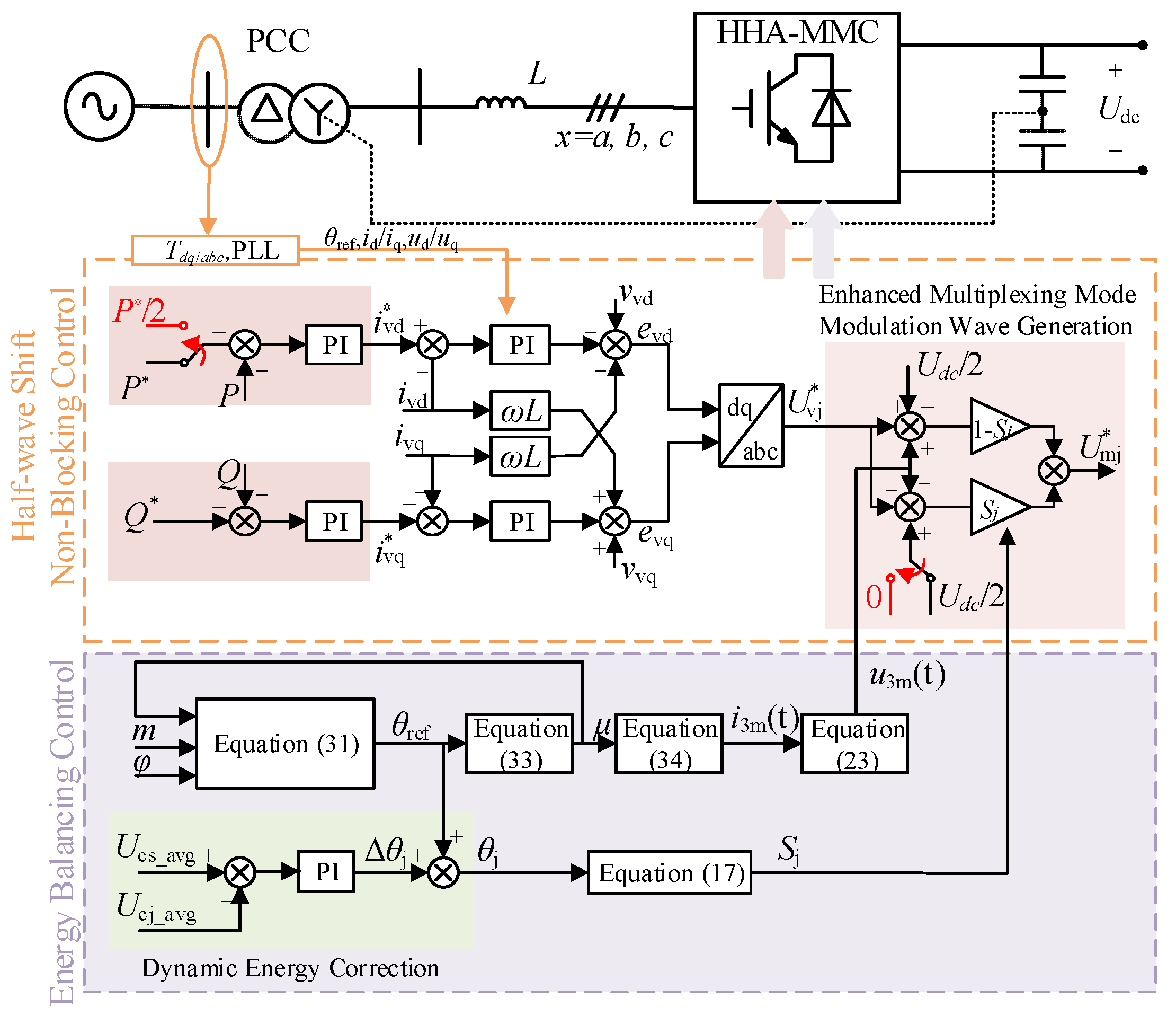
4.3. Control Diagram for Pole-to-Ground Fault Ride-Through Strategy

Figure 5 presents a diagram of the non-blocking fault ride-through strategy based on dual-modulation energy balancing control for the HHA-MMC under pole-to-ground fault, where P* and P, as well as Q* and Q, represent the reference values and actual values of active power and reactive power, respectively. id, iq and i d , i q represent the reference and actual values of the d-axis and q-axis current inner loops, and Umj indicates the three-phase voltage modulation wave.
The orange block diagram illustrates the half-wave shift non-blocking control strategy described in Section 4.1. Upon detecting a pole-to-ground fault, the arm modulation waveform is shifted downward during the faulty pole multiplexing half-cycle by utilizing the negative voltage output capability of FBSMs, thereby reducing the arm voltage by Udc/2. For converter stations operating in constant active power control mode, the power reference P* must be adjusted to half of its rated value. Furthermore, to address challenges including third-harmonic injection effects, submodule/switch parameter variations, and control delays, a semi-open-loop dual-modulation energy balancing strategy is designed to ensure rapid dynamic capacitor voltage balancing during external command transitions. As shown in the purple block diagram below, Equation (34) governs the coordinated injection of third-harmonic currents with phase-shifted angle delay switching to dissipate the energy accumulation caused by upper/lower-arm multiplexing asymmetry. Simultaneously, the control generates correction term θj based on the deviation between the three-phase submodule capacitor reference voltage Ucs_avg and the average capacitor voltage Ucj_avg of phase j, ensuring three-phase capacitor voltage balance.
In summary, by configuring only 61% FBSMs in the half-wave alternating multilevel converter and implementing a half-wave shift fault ride-through strategy with dual-modulation energy balancing control, it is possible to achieve rapid fault ride-through without blocking while realizing a lightweight design.

5. Simulation Results

To verify the fault characteristics and effectiveness of the proposed fault ride-through strategy, this paper builds a simplified two-terminal simulation model using Matlab/Simulink, shown in Figure 6. The sending-end employs the HHA-MMC with constant active/reactive power control. The receiving-end uses the conventional HF-MMC with constant voltage/reactive power control. Both converters apply Nearest Level Modulation (NLM), generating 21-level AC voltage output. This paper focuses on a pole-to-ground fault at the DC side, the model parameters are set as shown in Table 2, and the simulation uses an ode23tb solver with 10 μs step size and runs for a total of 3 s.

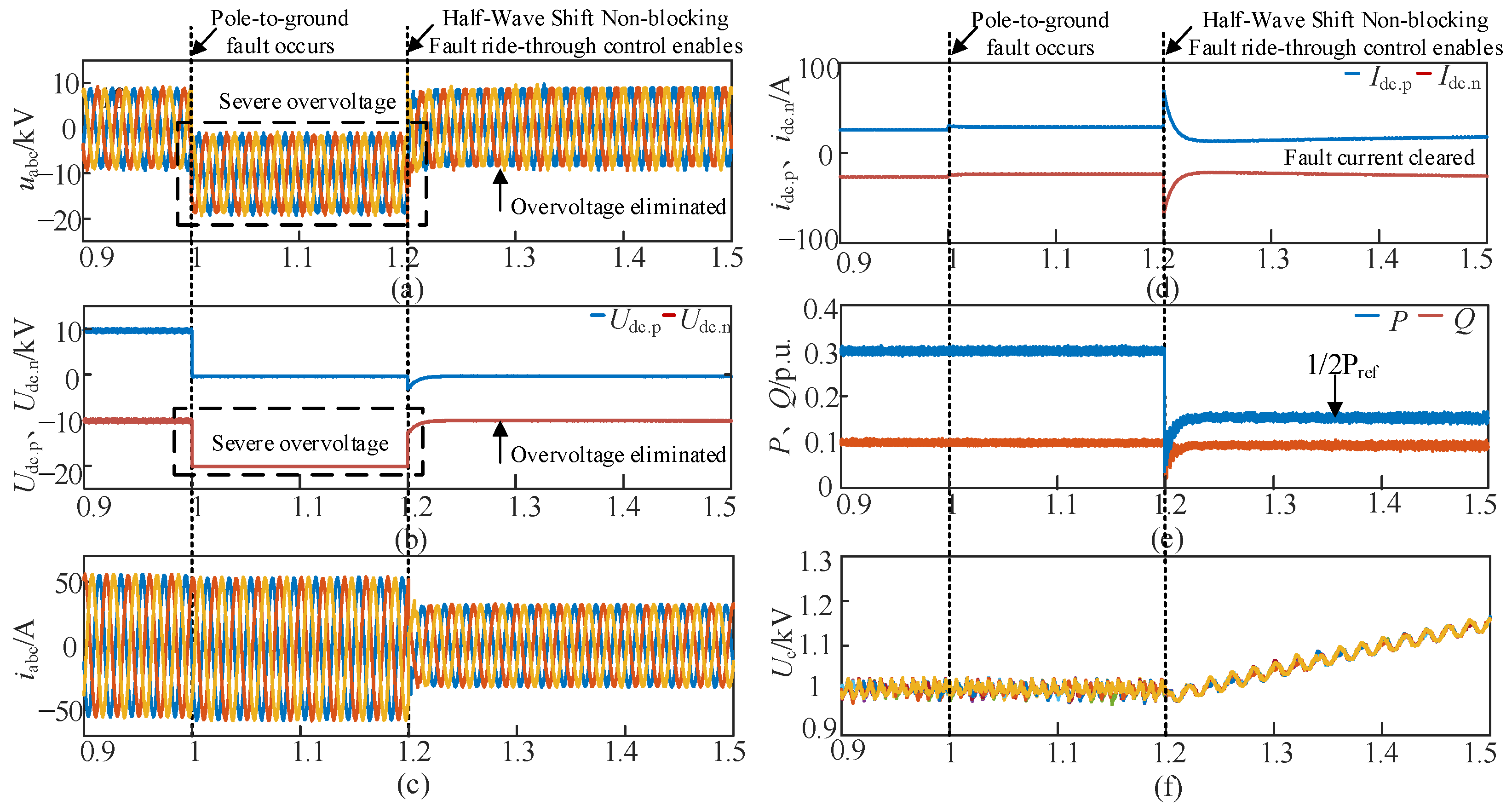
5.1. Fault Ride-Through Results for HF-MMC

To compare the pole-to-ground fault characteristics and non-blocking fault ride-through performance between HHA-MMC and conventional HF-MMC, a positive pole-to-ground DC short circuit fault is set for the DC bus when t = 1 s. After 0.2 s, the non-blocking fault ride-through strategy in Ref. [24] is applied to the HF-MMC. This strategy bypasses the upper-arm HBSMs, sets the upper-arm reference voltage to zero, and injects a fundamental frequency circulating current. The fault duration lasts for 1 s, after which normal DC voltage control and power transmission resume. The simulation results are shown in Figure 7.
When a positive pole-to-ground fault occurs, the positive pole DC voltage drops to zero, while the negative pole DC voltage increases from −10 kV to −20 kV. The upper-arm submodule capacitor voltages keep rising, and the lower-arm submodule capacitor voltages keep falling. After activating the control strategy at t = 1.2 s, the DC output voltage is reduced by half, eliminating the overvoltage on the negative pole. However, as evidenced in Figure 7g,h, during the fault ride-through process, the dynamic response remains slow and there is always a voltage difference between the upper-arm and lower-arm submodules in the HF-MMC. Therefore, the capacitor voltages of the sub-modules in the faulty pole and the healthy pole cannot be completely balanced.

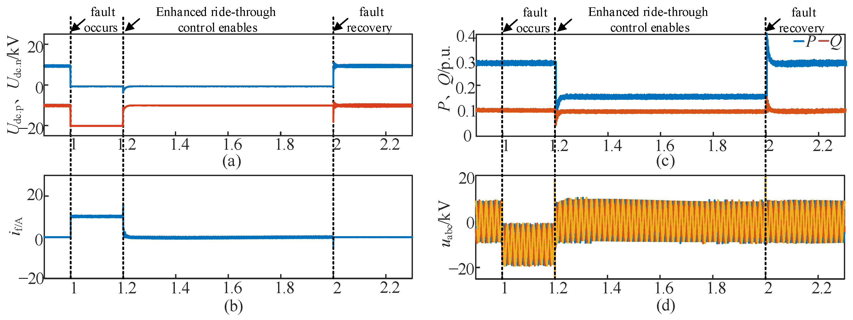
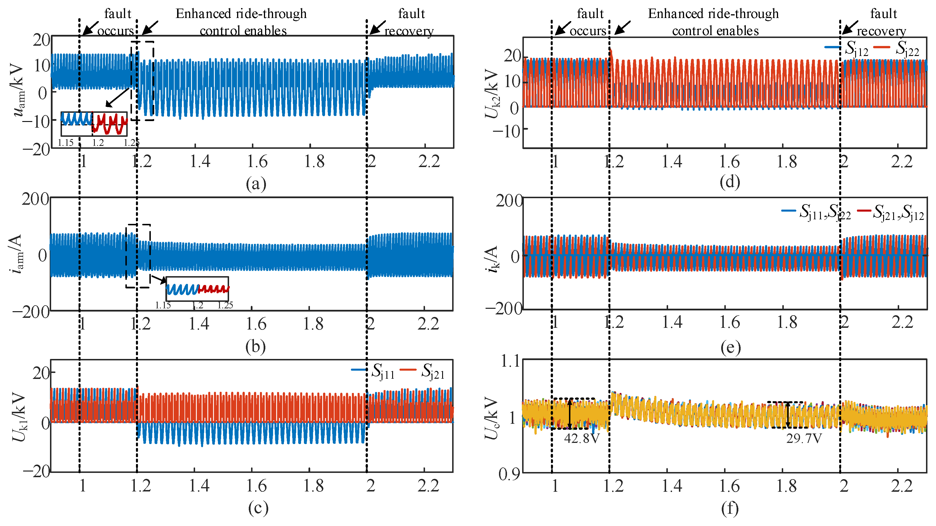
5.2. Fault Ride-Through Results for HHA-MMC

Set the same positive pole-to-ground fault configuration and duration at the DC bus outlet of the HHA-MMC as previously defined. When t = 1.2 s, only the half-wave shift non-blocking control is activated without implementing energy balancing. The simulation results are shown in Figure 8.
Figure 8a–f shows that when a positive pole-to-ground fault occurs on the DC bus, the positive DC voltage collapses to 0, while the negative DC voltage increases from −10 kV to −20 kV and the AC voltage at the converter valve-side outlet exhibits a DC offset of 10 kV in amplitude. Although the high-impedance grounding limits the fault current to a low magnitude, which enables continued power transmission with minimal active power fluctuations and stable capacitor voltages, the overvoltage issue is extremely severe. When the HHA-MMC lacks special insulation design, its voltage withstand capability is insufficient to suppress the DC overvoltage and voltage bias phenomena, ultimately leading to operational instability. Therefore, when t = 1.2 s, the half-wave shift non-blocking control strategy is activated, which biases the DC offset component to zero during the half-cycle of the upper-arm multiplexing mode and reduces the active power command to a 50% rated value. The HHA-MMC continues to alternate conduction in the improved multiplexing mode. Figure 8 shows that this strategy instantaneously eliminates the overvoltage of the AC/DC side and the fault current while maintaining a 50% rated active power and full reactive power transmission, effectively mitigating pole-to-ground fault transient stress. However, as evidenced in Figure 8a,f, this control strategy introduces capacitor voltage imbalance due to asymmetric energy distribution between the half-cycles of the improved upper/lower-arm multiplexing modes. Specifically, during improved upper-arm multiplexing intervals, continuous energy accumulation causes the progressive capacitor voltage to rise and there is a gradual increase in the AC-side value voltage, potentially triggering secondary overvoltage conditions.
To address this challenge, the half-wave shift non-blocking control strategy is enhanced through the incorporation of dual-modulation energy balancing control utilizing third-harmonic injection and phase-shifted angle adjustment. By substituting the measured simulation parameters into Equations (31) and (33), the optimized control parameters are determined as follows: the phase-shifted angle θ = −24.08°, the third-harmonic-to-fundamental current ratio μ = 0.58 and the initial phase angle α = −252.24°. When t = 1.2 s, a dual-modulation-based half-wave shift non-blocking fault ride-through strategy is activated. The fault is cleared at t = 2 s, and the HHA-MMC pole-to-ground fault ride-through simulation results are presented in Figure 9 and Figure 10.
Figure 9 shows that the improved arm modulation voltages implemented at t = 1.2 s successfully eliminate both fault current and DC bias by removing the DC component during upper-arm multiplexing cycles. Simultaneously, the coordinated injection of the third-harmonic current and phase-shifted angle-delayed switching resolves the problem of half-cycle energy accumulation, effectively addressing arm energy imbalance and enabling pole-to-ground fault ride-through with a 50% rated power transmission being maintained. Figure 10a,b demonstrates that both arm current and voltage waveforms undergo zero-crossing switching with a θ-phase delay, and the arm voltage decreased by Udc/2 during upper-arm intervals. Moreover, Figure 10c–e shows that both the AC-side arm selection switches and alternative switches normally operate with a delayed phase-shifted angle, maintaining voltage withstand and current conduction flow within rated limits. And Figure 10f confirms balanced submodule capacitor voltages with significantly reduced ripple, where the peak-to-peak capacitor voltage decreases from 42.8 V to 29.7 V. Following fault clearance at t = 2 s, the system rapidly resumes normal operation.

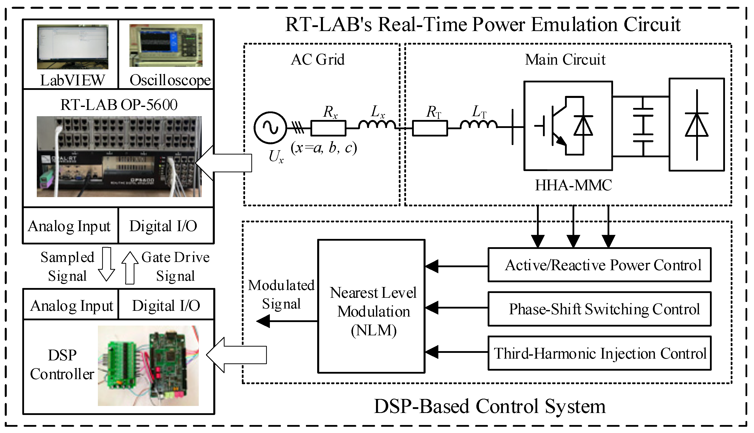
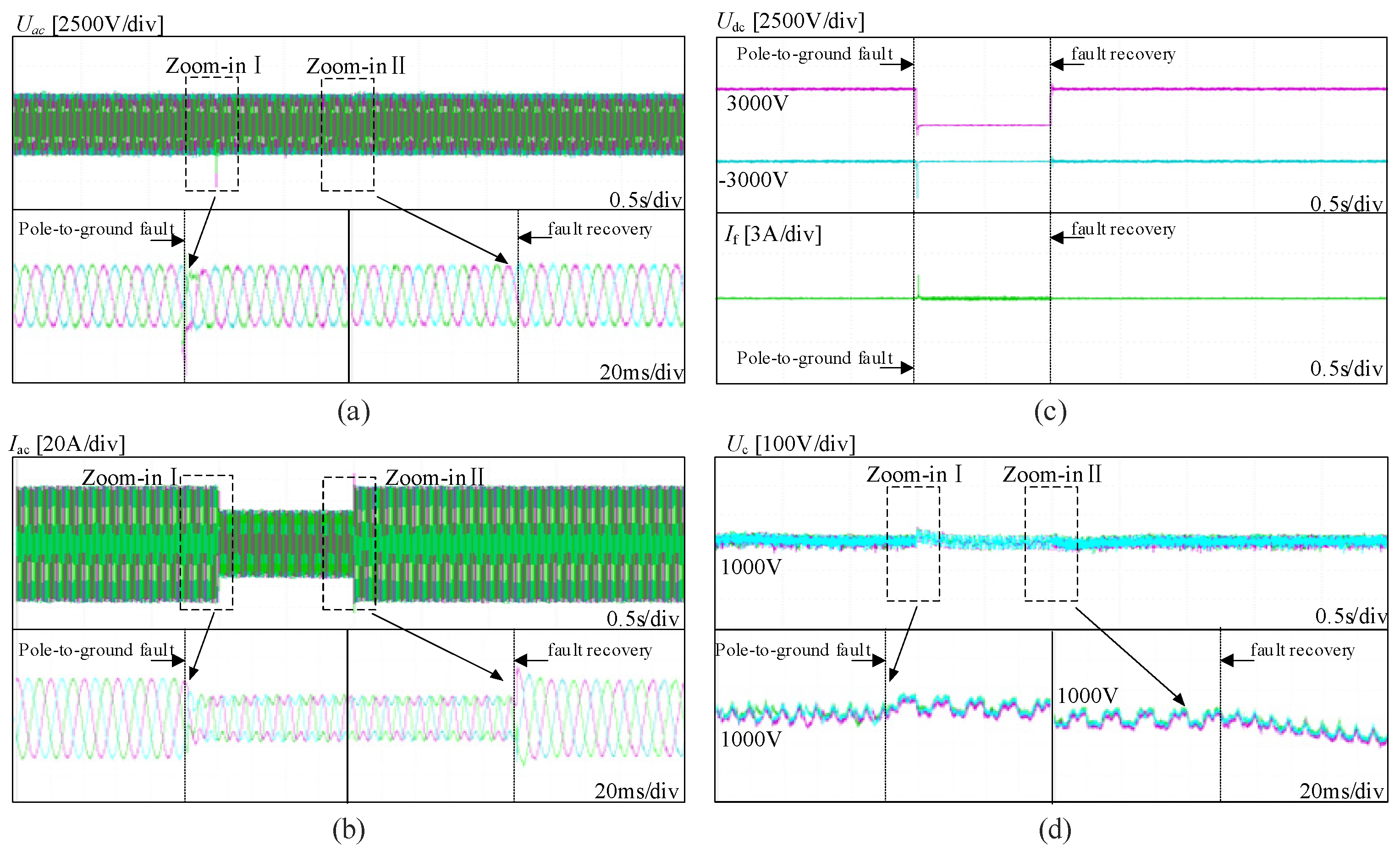
6. Experimental Validations

To further validate the effectiveness and engineering feasibility of the proposed strategy, the research team established a real-time HHA-MMC system model using an HIL experimental platform. As shown in Figure 11, it consists of host computer, RT-LAB (OP5600) (RTUNIT, Nanjing, China) real-time digital simulation platform, TMS320F28335 digital signal processor (DSP) controller (ICETEK, Beijing, China) and other devices. In the hardware-in-the-loop simulation experiment, to prevent data overflow caused by excessive submodules in the MMC main circuit, NLM was uniformly adopted, and the AC-side output voltage was set to seven levels, with each arm consisting of five submodules (0.82N). All other control parameters remained consistent with the simulation parameters presented in Section 5.
The real-time simulation model was downloaded to the target processor through the control port. The control system was implemented using the DSP control board and transmitted to the simulator via I/O cards, with a sampling frequency of 10 kHz. The experimental waveforms were sampled and then sent back to the digital controller for display on the oscilloscope. A pole-to-ground fault is set to occur at t1 = 2 s. Upon detecting the fault, the proposed ride-through strategy was immediately activated. At t2 = 3 s, the fault is restored. The experimental waveforms of AC-side voltage and current, DC-side voltage and current, and submodule capacitor voltages are shown in Figure 12.
As shown in Figure 12, the HHA-MMC successfully achieves fault ride-through capability without blocking. The proposed strategy effectively eliminates the DC offset of AC-side, DC-side overvoltage, and fault current. And the AC-side current reduces to half of its pre-fault value due to temporary active power reduction during the fault ride-through period. Furthermore, the strategy successfully regulates the submodule capacitor voltages back to their rated values, reducing the voltage fluctuation rate from 4.28% to 2.97%, indicating excellent energy balancing performance. The experimental results exhibit consistent characteristics with the simulation results, further validating the effectiveness of the proposed strategy.

7. Conclusions

We designed a hybrid half-wave alternating modular multilevel converter (HHA-MMC) and analyzed its pole-to-ground fault characteristics. Subsequently, a half-wave shift non-blocking fault ride-through strategy with dual-modulation energy balancing control based on the third-harmonic current and phase-shifted angle was proposed. The effectiveness of the proposed strategy was validated via MATLAB/Simulink and HIL experiments, and the key conclusions are as follows:
(1)
Compared with the conventional HF-MMC, the proposed HHA-MMC configured with 61% FBSMs achieved comparable fault ride-through capability while reducing the submodule count by 59%, demonstrating significant advantages in converter lightweight design and operational reliability.
(2)
Based on the full-time arm multiplexing characteristic of the HHA-MMC, a half-wave shift non-blocking fault ride-through strategy was proposed. By utilizing the negative voltage output capability of FBSMs to adjust the arm output voltage exclusively during the faulty pole conduction half-cycle, the strategy effectively eliminated both fault current and system overvoltage.
(3)
To address the arm energy imbalance, a dual-modulation energy balancing control based on third-harmonic injection and phase-shifted angle adjustment was proposed to dissipate accumulated arm energy. This strategy maintains capacitor voltages near nominal values while significantly reducing voltage ripple, demonstrating excellent energy equilibrium performance.

Author Contributions

Conceptualization, Y.D. and Y.W.; methodology, Y.D.; validation, Y.D., Y.G. (Yuhua Gao) and Z.S.; formal analysis, Y.G. (Yuhua Gao) and Y.G. (Yilei Gu); investigation, Z.S. and Y.D.; data curation, Y.W.; writing—original draft preparation, Y.D.; writing—review and editing, Y.W. and X.S.; visualization, X.W.; supervision, Y.W.; project administration, Y.W. and Y.G. (Yilei Gu); funding acquisition, Y.W. and Y.G. (Yilei Gu). All authors have read and agreed to the published version of the manuscript.

Funding

This research was funded by the National Natural Science Foundation of China under Grant No. 52077079 and the Science and Technology Project of State Grid Zhejiang Electric Power Co., Ltd. under Grant No. 5211DS24000D.

Data Availability Statement

The data that support the findings of this study are available from the corresponding author upon reasonable request.

Conflicts of Interest

Author Yilei Gu was employed by the company State Grid Zhejiang Electrical Power Co., Ltd. The remaining authors declare that the research was conducted in the absence of any commercial or financial relationships that could be construed as a potential conflict of interest.

Nomenclature

HHA-MMCHybrid half-wave alternating modular multilevel converter
SMSubmodule
HBSMHalf-bridge submodule
FBSMFull-bridge submodule
DCCBDC circuit breaker
SjSwitching function of phase j (j = a, b, c)
mVoltage modulation ratio
UdcDC voltage (V)
UmFundamental frequency amplitudes of the AC phase voltage (V)
ImFundamental frequency amplitudes of the AC phase current (A)
IfTotal fault current (A)
ΔEmMultiplexed arm’s energy accumulation
ΔucjCapacitive voltage deviation
φPower factor angle
θAdjustable phase-shifted angle
U3mTriple frequency amplitudes of the AC phase voltage (V)
I3mTriple frequency amplitudes of the AC phase current (A)
αInitial phase angle of the third-harmonic current
μRatio of the third-harmonic current to the fundamental current amplitude

References

  1. Wang, W.; Li, G.; Guo, J. Large-Scale Renewable Energy Transmission by HVDC: Challenges and Proposals. Engineering 2022, 19, 252–267. [Google Scholar] [CrossRef]
  2. Zhang, Y.; Ravishankar, J.; Fletcher, J.; Li, R.; Han, M. Review of Modular Multilevel Converter Based Multi-Terminal HVDC Systems for Offshore Wind Power Transmission. Renew. Sustain. Energy Rev. 2016, 61, 572–586. [Google Scholar] [CrossRef]
  3. Dekka, A.; Wu, B.; Fuentes, R.L.; Perez, M.; Zargari, N.R. Evolution of Topologies, Modeling, Control Schemes, and Applications of Modular Multilevel Converters. IEEE J. Emerg. Sel. Top. Power Electron. 2017, 5, 1631–1656. [Google Scholar] [CrossRef]
  4. Wang, C.; Xu, J.; Pan, X.; Gong, W.; Zhu, Z.; Xu, S. Impedance Modeling and Analysis of Series-Connected Modular Multilevel Converter (MMC) and Its Comparative Study with Conventional MMC for HVDC Applications. IEEE Trans. Power Deliv. 2022, 37, 3270–3281. [Google Scholar] [CrossRef]
  5. Debnath, S.; Qin, J.; Bahrani, B.; Saeedifard, M.; Barbosa, P. Operation, Control, and Applications of the Modular Multilevel Converter: A Review. IEEE Trans. Power Electron. 2015, 30, 37–53. [Google Scholar] [CrossRef]
  6. Li, R.; Yu, L.; Xu, L.; Adam, G.P. Coordinated Control of Parallel DR-HVDC and MMC-HVDC Systems for Offshore Wind Energy Transmission. IEEE J. Emerg. Sel. Top. Power Electron. 2020, 8, 2572–2582. [Google Scholar] [CrossRef]
  7. Ma, D.; Chen, W.; Shu, L.; Qu, X.; Hou, K. A MMC-Based Multiport Power Electronic Transformer with Shared Medium-Frequency Transformer. IEEE Trans. Circuits Syst. II Express Briefs 2021, 68, 727–731. [Google Scholar] [CrossRef]
  8. Lacerda, V.A.; Monaro, R.M.; Campos-Gaona, D.; Pena-Alzola, R.; Coury, D.V. An Approximated Analytical Model for Pole-to-Ground Faults in Symmetrical Monopole MMC-HVDC Systems. IEEE J. Emerg. Sel. Top. Power Electron. 2021, 9, 7009–7017. [Google Scholar] [CrossRef]
  9. Li, X.; Song, Q.; Liu, W.; Rao, H.; Xu, S.; Li, L. Protection of Nonpermanent Faults on DC Overhead Lines in MMC-Based HVDC Systems. IEEE Trans. Power Deliv. 2013, 28, 483–490. [Google Scholar] [CrossRef]
  10. Fan, S.; Chen, C.; Yang, H.; Xiang, X.; Yang, H.; Li, W.; He, X. A Cost-Effective and DC-Fault Tolerant Alternate Arm Converter with Wide Range Voltage Adaptability. IEEE J. Emerg. Sel. Top. Power Electron. 2022, 10, 6673–6686. [Google Scholar] [CrossRef]
  11. Hu, J.; Xiang, M.; Lin, L.; Lu, M.; Zhu, J.; He, Z. Improved Design and Control of FBSM MMC with Boosted AC Voltage and Reduced DC Capacitance. IEEE Trans. Ind. Electron. 2018, 65, 1919–1930. [Google Scholar] [CrossRef]
  12. Sun, P.; Tian, Y.; Pou, J.; Konstantinou, G. Beyond the MMC: Extended Modular Multilevel Converter Topologies and Applications. IEEE Open J. Power Electron. 2022, 3, 317–333. [Google Scholar] [CrossRef]
  13. Wang, Y.; Li, Y.; Wang, C.; Tao, J. A Hybrid Arm-multiplexing MMC for DC Fault Ride-through without Blocking. IET Renew. Power Gener. 2023, 17, 2225–2235. [Google Scholar] [CrossRef]
  14. Merlin, M.M.C.; Green, T.C.; Mitcheson, P.D.; Trainer, D.R.; Critchley, R.; Crookes, W.; Hassan, F. The Alternate Arm Converter: A New Hybrid Multilevel Converter with DC-Fault Blocking Capability. IEEE Trans. Power Deliv. 2014, 29, 310–317. [Google Scholar] [CrossRef]
  15. Yu, Y.; Gao, Y.; Wang, Y.; Li, Y.; Su, Z.; Wang, R. A Half-Wave Alternating Multilevel Converter with High Submodule Utilization. In Proceedings of the IECON 2023—49th Annual Conference of the IEEE Industrial Electronics Society, Singapore, 16 October 2023; IEEE: Singapore, 2023; pp. 1–6. [Google Scholar]
  16. Huang, M.; Li, W.; Zou, J.; Ma, X. Analysis and Design of a Novel Hybrid Modular Multilevel Converter with Time-Sharing Alternative Arm Converter. IEEE Trans. Ind. Electron. 2024, 71, 14–26. [Google Scholar] [CrossRef]
  17. Ma, J.; Peng, Y.; Su, Z.; Gu, Y.; Ni, Q.; Yang, Y.; Wang, Y.; Liu, J. Half-Wave Phase Shift Modulation for Hybrid Modular Multilevel Converter with Wide-Range Operation. Electronics 2024, 13, 3556. [Google Scholar] [CrossRef]
  18. Zhao, C.; Li, T.; Yu, L.; Huang, Y.; Li, L.; Li, X. DC pole-to-ground fault characteristic analysis and converter fault recovery strategy of MMC-HVDC. Proc. CSEE 2014, 34, 3518–3526. [Google Scholar]
  19. Lee, Y.; Cui, S.; Kim, S.; Sul, S.-K. Control of Hybrid HVDC Transmission System with LCC and FB-MMC. In Proceedings of the 2014 IEEE Energy Conversion Congress and Exposition (ECCE), Pittsburgh, PA, USA, 15–18 September 2014; IEEE: Pittsburgh, PA, USA, 2014; pp. 475–482. [Google Scholar]
  20. Luo, Y.; Xu, L.; Xiong, X.; Li, Y. Pole-to-ground DC fault protection of MMC-MTDC systems. Trans. China Electrotech. Soc. 2017, 32, 98–106. [Google Scholar]
  21. Cui, S.; Sul, S.-K. A Comprehensive DC Short-Circuit Fault Ride through Strategy of Hybrid Modular Multilevel Converters (MMCs) for Overhead Line Transmission. IEEE Trans. Power Electron. 2016, 31, 7780–7796. [Google Scholar] [CrossRef]
  22. Lin, W.; Jovcic, D.; Nguefeu, S.; Saad, H. Full-Bridge MMC Converter Optimal Design to HVDC Operational Requirements. IEEE Trans. Power Deliv. 2016, 31, 1342–1350. [Google Scholar] [CrossRef]
  23. Zeng, R.; Xu, L.; Yao, L.; Finney, S.J. Analysis and Control of Modular Multilevel Converters under Asymmetric Arm Impedance Conditions. IEEE Trans. Ind. Electron. 2016, 63, 71–81. [Google Scholar] [CrossRef]
  24. Lu, M.; Hu, J.; Zeng, R.; He, Z. Fundamental-Frequency Reactive Circulating Current Injection for Capacitor Voltage Balancing in Hybrid-MMC HVDC Systems during Riding through PTG Faults. IEEE Trans. Power Deliv. 2018, 33, 1348–1357. [Google Scholar] [CrossRef]
  25. Xiang, W.; Lin, W.; Xu, L.; Wen, J. Enhanced Independent Pole Control of Hybrid MMC-HVdc System. IEEE Trans. Power Deliv. 2018, 33, 861–872. [Google Scholar] [CrossRef]
  26. Wang, Y.; Yuan, Z.; Fu, J. A Novel Strategy on Smooth Connection of an Offline MMC Station into MTDC Systems. IEEE Trans. Power Deliv. 2016, 31, 568–574. [Google Scholar] [CrossRef]
Figure 1. Simplified topology of HHA-MMC.
Electronics 14 02893 g001
Figure 2. Operation mode of HHA-MMC.
Electronics 14 02893 g002
Figure 3. Fault current path and equivalent circuit (DC positive pole-to-ground fault).
Electronics 14 02893 g003
Figure 4. Half-wave shift improved multiplexing mode modulation principle of HHA-MMC.
Electronics 14 02893 g004
Figure 5. Diagram of non-blocking half-wave fault ride-through strategy based on dual-modulation energy balancing for HHA-MMC under pole-to-ground fault.
Electronics 14 02893 g005
Figure 6. Simplified model of HHA-MMC and HF-MMC for MVDC grids.
Electronics 14 02893 g006
Figure 7. Simulation results of non-blocking fault ride-through strategy with fundamental frequency circulating current injection for conventional HF-MMC. (a) Positive and negative DC voltages. (b) DC fault current. (c) AC voltage. (d) AC current. (e) Upper arm current of phase a. (f) Lower arm current of phase a. (g) Upper arm SM capacitor voltage of phase a. (h) Lower arm SM capacitor voltage.
Electronics 14 02893 g007
Figure 8. Simulation results with half-wave shift non-blocking fault ride-through control. (a) AC voltage. (b) Positive and negative DC voltages. (c) AC current. (d) Positive and negative dc currents. (e) Active and reactive powers. (f) SM capacitor voltage.
Electronics 14 02893 g008
Figure 9. Simulation results of half-wave shift fault ride-through strategy with dual-modulation energy balancing strategy control for HHA-MMC. (a) Positive and negative DC voltages. (b) DC fault current. (c) Active and reactive powers. (d) AC voltage.
Electronics 14 02893 g009
Figure 10. Arm electrical quantities under half-wave shift fault ride-through strategy with dual-modulation energy balancing control for HHA-MMC. (a) Arm voltage of phase a. (b) Arm current of phase a. (c) Arm selection switch voltage of phase a. (d) Alternative switch voltage of phase a. (e) Switch current of phase a. (f) SM capacitor voltage of phase a.
Electronics 14 02893 g010
Figure 11. Implementation scheme of HIL experiment platform for HHA-MMC system.
Electronics 14 02893 g011
Figure 12. HHA-MMC fault ride-through experimental waveforms with proposed control strategy. (a) AC voltage. (b) AC current. (c) Positive/negative DC voltages and DC fault current. (d) SM capacitor voltages.
Electronics 14 02893 g012
Table 1. Main device quantities of HHA-MMC and HF-MMC.
ConverterSubmodule CapacitorIGBT
HHA-MMC0.82N × 36.64N × 3
HF-MMC2N × 36N × 3
Table 2. Simulation parameters.
ParametersSymbolValues
DC-link voltageUdc20 kV
Number of SMs per phase0.82N17
Modulation ratiom0.816
SM capacitorC3 mF
SM capacitor rated voltageUcN1000 V
Cable resistanceRdc9.3 Ω
Cable inductanceLdc10 mH
DC-side filter capacitanceCdc2 mF
Grounding resistanceRg1000 Ω
Disclaimer/Publisher’s Note: The statements, opinions and data contained in all publications are solely those of the individual author(s) and contributor(s) and not of MDPI and/or the editor(s). MDPI and/or the editor(s) disclaim responsibility for any injury to people or property resulting from any ideas, methods, instructions or products referred to in the content.

