Article

Reconstruction of Impedance Criteria and Stability Enhancement Strategies for Grid-Connected Inverters

School of Information Engineering, Nanchang University, Nanchang 330031, China
*
Author to whom correspondence should be addressed.
Electronics 2025, 14(22), 4402; https://doi.org/10.3390/electronics14224402
Submission received: 9 October 2025 / Revised: 6 November 2025 / Accepted: 10 November 2025 / Published: 12 November 2025
(This article belongs to the Special Issue Applications, Control and Design of Power Electronics Converters)

Abstract

Grid-connected inverters play an indispensable and crucial role between new energy power generation devices and the power grid. As an important method for stability analysis of grid-connected inverters, impedance criteria have been widely applied. However, traditional impedance criteria have the problem of inaccurately representing system stability margins. Moreover, under weak grid conditions where grid impedance cannot be ignored, voltage disturbances at the point of common coupling will cause phase angle deviations in the output of the phase-locked loop, thereby affecting the stability of the control system. To address these issues, this paper establishes a stability analysis model based on the reshaping of impedance criteria and proposes a q-axis improved control compensation method, which expands the adaptability range of grid impedance for inverters and enhances the stability of grid-connected inverters. Finally, the correctness of the proposed algorithm is verified through experiments.

1. Introduction

Due to their environmentally friendly and renewable nature, new energy sources have become increasingly important in today’s society facing energy shortages, thereby promoting the continuous advancement of new energy generation technologies [1,2]. As a bridge between renewable energy generation units and the power grid, grid-connected inverters are responsible for injecting the generated electrical energy into the grid in a stable and high-quality manner [3,4]. However, certain renewable generation units are connected at the end of the grid, where long transmission lines make the line impedance non-negligible. In contrast, off-grid residential photovoltaic systems, which lack long-distance transmission lines, have very small or even negligible line impedance. Therefore, grid-connected inverters for renewable energy operate under conditions with significant variations in line impedance, and the impedance characteristics can significantly impact their stable operation [5,6]. Consequently, stability analysis of renewable energy grid-connected inverters under a wide range of line impedance conditions has significant practical engineering value.
References [7,8] analyze the stability of the control system by establishing the state-space matrix of the grid-connected inverter and plotting the eigenvalues of the state transition matrix. However, when analyzing complex current controllers or multi-inverter parallel systems, the dimension of the state-space matrix becomes very large, leading to difficulties in modeling and increased analytical complexity. References [9,10] investigate the stability of the control system by developing an output impedance model of the grid-connected inverter and applying the impedance-based criterion. Nevertheless, the traditional impedance criterion suffers from inaccuracy in determining the stability margin. Reference [11] points out that the stability of grid-connected inverters is determined by two aspects: the initial parameters of the system control loop and the interaction between the inverter output impedance and the grid impedance. Therefore, the system stability margin must comprehensively account for both factors and cannot be replaced solely by the impedance interaction in the conventional impedance criterion. However, the study does not consider the impact of phase angle deviations in the phase-locked loop (PLL) on the inverter output impedance.
Reference [12] reduces the impact of phase angle deviations from the phase-locked loop (PLL) on the inverter output impedance by lowering the PLL bandwidth; however, this approach deteriorates the dynamic performance of the control system. To address this issue, References [13,14] modify the PLL structure, enabling the system to maintain strong immunity against grid impedance disturbances even under high bandwidth. Nevertheless, the PLL configuration becomes overly complex, making modeling and stability analysis difficult. Without altering the PLL structure or bandwidth, References [15,16] enhance the magnitude and phase of the inverter output impedance by introducing virtual impedance into the current control loop, thereby preventing instability caused by an insufficient phase margin at the crossover frequency. However, this method increases the regulation time of the control system. References [17,18] develop an inverter output impedance model that accounts for PLL phase angle deviations and analyzes both the extent and mechanism of their impact on the control system. Building on this, Reference [19] introduces a PLL phase-angle disturbance compensation term into the control loop to counteract the adverse effects of PLL phase deviations. This method improves the magnitude and phase margin of the inverter output impedance in the low- and mid-frequency range; nevertheless, as the frequency increases, its ability to enhance the phase margin at the crossover frequency diminishes, leaving the risk of instability under wide variations in grid impedance.
To enhance the adaptability of grid-connected inverters under wide variations in grid impedance and to accurately reflect the actual phase margin of the system, this paper first proposes a stability analysis method based on reshaped impedance criteria. This method can precisely characterize the true stability margin of the system and provides a theoretical foundation for evaluating the stability of grid-connected inverters under different grid conditions. On this basis, a novel compensation control method is further proposed by introducing a PLL disturbance compensation term into the control system. This method effectively improves the phase margin at the high-frequency crossover point and enhances the inverter’s adaptability to wide-range grid impedance.

2. VSG Control Principle and Performance Analysis

Figure 1 shows the main circuit model of the grid-connected inverter and its control block diagram, where Udc is the DC voltage; Cdc1 and Cdc2 are the DC-link capacitors; Lf1, Lf2 and Cf are the inductors and capacitor of the LCL filter; Lg is the grid-side inductor; ea, eb and ec are the grid voltages; uao, ubo and uco are the bridge arm output voltages; ica, icb and icc are the filter capacitor currents, expressed in the α β -axis as i c α and i c β ; uga, ugb and ugc are the inverter output voltages; iga, igb and igc are the inverter output currents, expressed in the dq-axis as igd and igq; θ p l l is the output angle of the PLL; igdref and igqref are the dq-axis current reference values; Kf is the decoupling term and equals ω n L f 1 + L f 2 where ω n is the rated angular frequency of the grid; Kd is the active damping coefficient; and kp and ki are the proportional and integral coefficients of the PI controller, respectively.
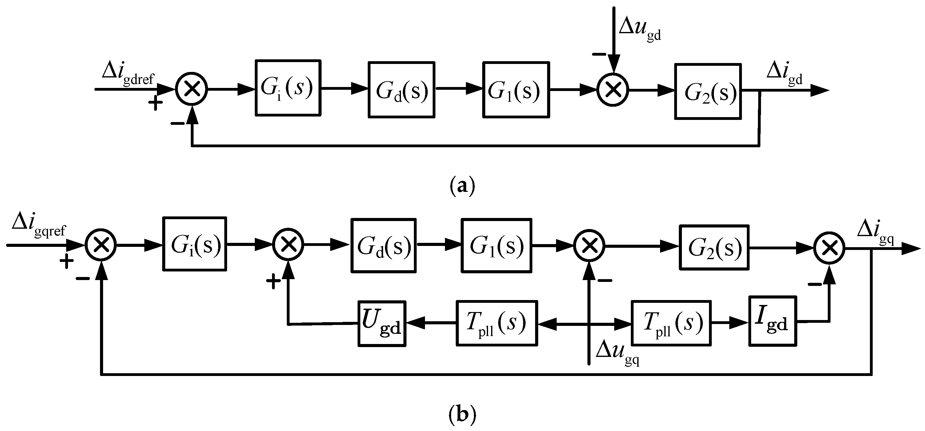
Under weak grid conditions, dynamic disturbances between the grid impedance and the inverter cause a phase difference Δθ between the actual phase angle of the grid voltage and the output angle of the PLL. According to the conclusion of Reference [20], the dq-axis closed-loop small-signal equivalent model of the grid-connected inverter under the influence of Δθ is as shown in Figure 2. In the figure, Kd is the active damping coefficient; ugd and ugq are the small-signal expressions of the PCC voltage in the dq-axis; igd and igq are the small-signal expressions of the PCC current in the dq-axis; igd_ref and igq_ref are the small-signal expressions of the PCC current references in the dq-axis; Tpll(s) is the transfer function of the PLL; Ugd and Igd are the rated values of the PCC voltage and current on the d-axis; Gd(s) is the delay function; G1(s) and G2(s) are the equivalent transfer functions of the simplified control links; and Gi(s) is the transfer function of the PI regulator in the current loop. The expressions of the coefficients are as follows:
G 1 ( s ) = 1 / 1 + s C f K d G d ( s ) + s 2 L f 1 C f G 2 ( s ) = 1 + s C f k d G d ( s ) + s 2 L f 1 C f / m de ( s ) m de ( s ) = s ( L f 1 + L f 2 ) + s 2 L f 2 C f k d G d ( s ) + s 3 L f 1 L f 2 C f G d ( s ) = e 1.5 s T s G i ( s ) = k p + k i / s H pll s = k ppll + k ipll / s T pll s = H pll s / s U gd H pll s
In the equation, kppll is the proportional coefficient of the PLL; kipll is the integral coefficient of the PLL; and Ts is the sampling time constant.
As shown in Figure 2, Δθ only affects the q-axis, which leads to poorer stability on the q-axis compared to the d-axis. The grid-connected inverter model established in this paper takes the influence of Δθ into account. To avoid repetitive analysis, the subsequent discussion focuses solely on the q-axis, which exhibits weaker stability. In this case, the output impedance expression of the grid-connected inverter is given by:
T A ( s ) = G i ( s ) G d ( s ) G 1 ( s ) G 2 ( s ) Z ( s ) = 1 + T A ( s ) G 2 ( s ) + G pll ( s ) T A ( s ) I gd + U gd G i ( s )
In the equation, Z(s) denotes the output impedance of the inverter, and TA(s) represents the forward channel gain.

3. Reshaped Impedance Criterion of Grid-Connected Inverters

3.1. Reshaped Impedance Criterion

The equivalent model of the grid-connected inverter is shown in Figure 3, where Zg(s) denotes the grid impedance, Ug(s) the grid voltage, Ig(s) the grid-side current, and Is(s) the inverter output current. According to Figure 3, the grid current can be expressed as:
I g ( s ) = H x 1 ( s ) H x 2 ( s ) H x 1 ( s ) = I s ( s ) U g ( s ) / Z ( s ) H x 2 ( s ) = 1 / [ 1 + Z g ( s ) / Z ( s ) ]
According to Equation (3), the stability of the grid-connected system is jointly determined by Hx1(s) and Hx2(s). Among them, Hx1(s) involves only controller parameters, whose stability is ensured during the initial design stage, while Hx2(s) characterizes the dynamic interaction between the inverter output impedance and the grid impedance. Under weak grid conditions, variations in grid impedance may cause oscillatory instability in the control system. Therefore, Hx2(s) can serve as the stability criterion of the system under weak grid conditions. Based on the Nyquist stability criterion, when the control system is stable, the phase margin PM1 at the crossover frequency of Z(s) and Zg(s) is greater than zero, i.e., Equation (4) is greater than zero.
Reference [7] points out that the traditional stability criterion not only relies on Hx2(s) to evaluate the stability of the control system but also uses Hx2(s) to quantify the stability margin. However, the actual stability margin of the system is affected not only by Hx2(s) but also by Hx1(s). Therefore, the traditional stability margin evaluation method based solely on Hx2(s) introduces errors and cannot fully reflect the true stability of the system. The reference divides the inverter output impedance Z(s) into two parts, Z t 1 ( s ) and Z t 2 ( s ) . In this case, the ratio Z t 1 ( s ) / [ Z t 2 ( s ) + Z g ( s ) ] is equivalent to the open-loop transfer function of the system. This newly defined impedance ratio can accurately reflect the stability margin of the current control loop and eliminates the steady-state errors inherent in traditional methods. According to the conclusions on the reconstruction of the impedance criterion presented in the reference, the inverter output impedance model is as shown in Figure 4, where the expressions of the two impedance components in the d, q reference frame are given in Equation (5), and the corresponding phase margin calculation method is presented in Equation (6).
P M 1 = 180 + { arg [ Z ( s ) ] arg [ Z g ( s ) ] }
Z t 1 s = T A s G x 2 s + G pll s T A s [ I gd + U gd / G i s ] Z t 2 s = 1 G x 2 s + G pll s T A s [ I gd + U gd / G i s ]
P M 2 = 180 a r g [ Z t ( s ) ] a r g [ Z t 1 ( s ) ]
In the equation, Zt(s) is equal to the sum of Zt2(s) and Zg(s).

3.2. Comparison Between the Reshaped Impedance Criterion and the Traditional Criterion

As the reshaped impedance criterion proposed in Reference [7] fails to account for the influence of Δθ and the controller delay, this study, based on the previously established impedance model that considers both Δθ and controller delay, conducts a comparative analysis between the improved impedance criterion and the traditional impedance criterion to highlight the advantages of the improved method.
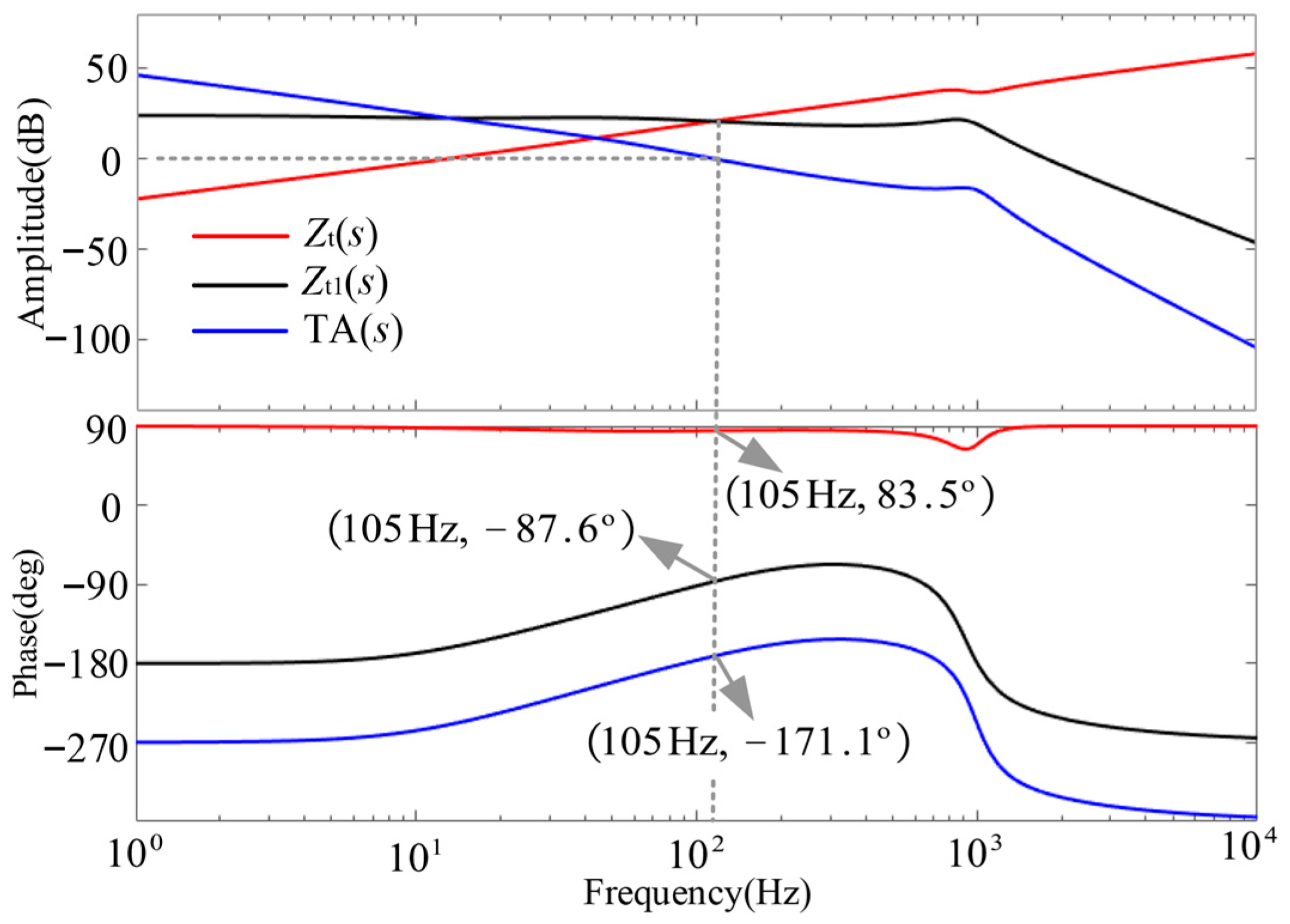
As shown in Figure 5, when Lg is 15 mH, the crossover frequency between Zt(s) and Zt1(s) is 105 Hz. At this frequency, the phase difference between Zt(s) and Zt1(s) ranges from 83.5° to 87.6°. According to Equation (10), the phase margin is calculated to be 8.9°. The cutoff frequency of TA(s) is also 105 Hz, where the phase is −171.1°, resulting in a phase margin of 8.9°. Therefore, under the reshaped impedance criterion, the control system is regarded as stable. Moreover, the phase margin obtained from the reshaped impedance criterion is equal to the actual phase margin of the open-loop transfer function.
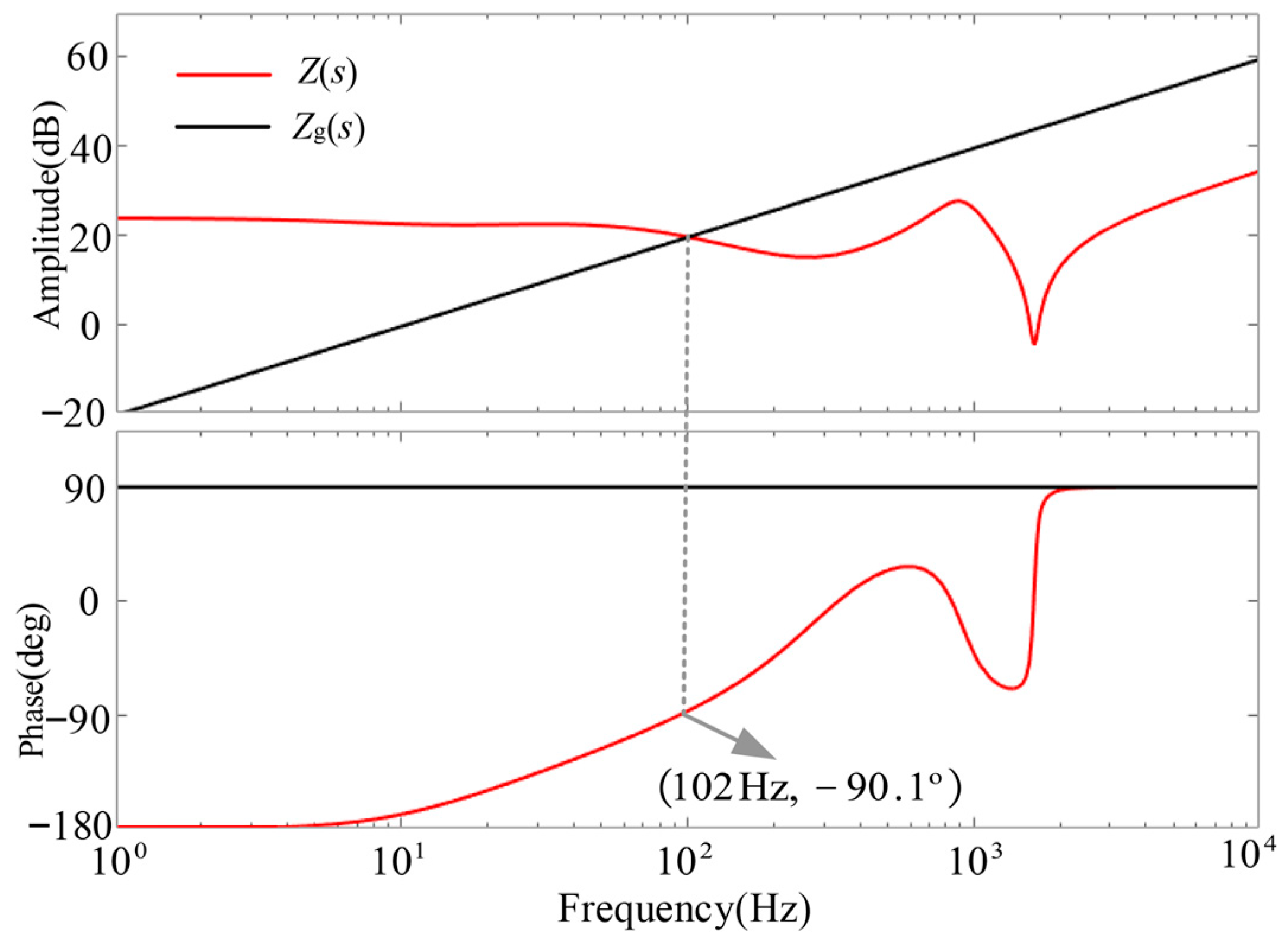
As shown in Figure 6, when Lg is 15 mH and the traditional impedance criterion is applied, the crossover frequency between Z(s) and Zg(s) is 102 Hz. At this frequency, the phase difference between Z(s) and Zg(s) ranges from −90.1° to −90°, and according to Equation (8), the phase margin is less than zero. In this case, the traditional impedance criterion concludes that the control system is unstable.
By comparing the results before and after applying the reshaped impedance criterion, it can be seen that the phase margin obtained through the reshaped criterion is consistent with the actual phase margin of the system’s open-loop transfer function, accurately reflecting the system’s stability margin. In contrast, the traditional impedance criterion provides results inconsistent with the actual system stability margin, leading to errors in stability assessment. The experimental validation of these results will be presented in Section 3.1.
As shown in Figure 6, the output impedance phase of Z(s) is less than −90° in the low-frequency range, indicating that the control system is unstable within this frequency band. As the grid impedance increases, the crossover frequency gradually shifts toward the low-frequency region, which further leads to system instability.

3.3. q-Axis Control Compensation Strategy

To improve the phase of the inverter output impedance in the low-frequency range, Reference [12] introduces a disturbance feedback term into the q-axis to counteract the influence of PLL disturbance on the q-axis. As shown in Figure 7, after introducing disturbance compensation into the q-axis, its transfer function becomes identical to that of the d-axis in Figure 2a. In this case, the output impedance of the inverter is expressed as Equation (7), and the phase margin is given by Equation (8):
Z t 1 1 ( s ) = T A ( s ) / G x 2 ( s ) Z t 2 1 ( s ) = 1 / G x 2 ( s )
P M 3 = 180 a r g [ Z t 1 ( s ) ] a r g [ Z t 1 1 ( s ) ]
In the equation, Z t 1 s is equal to the sum of Z t 1 1 s and Zg(s).
When Lg is 15 mH and the q-axis introduces disturbance feedback compensation, the Bode diagram of the inverter output impedance and the grid impedance is as shown in Figure 8. At this time, the crossover frequency between Z t 1 s and Z t 1 1 s is 121 Hz, and the phases of Z t 1 s and Z t 1 1 s at the crossover frequency are 83.6° and −66.2°, respectively. According to Equation (8), the phase margin at this point is 30.2°. Compared with Figure 5, under the same grid impedance condition, after introducing disturbance compensation into the q-axis, the phase margin increases from 8.9° to 30.2°, thereby improving the robustness of the control system.
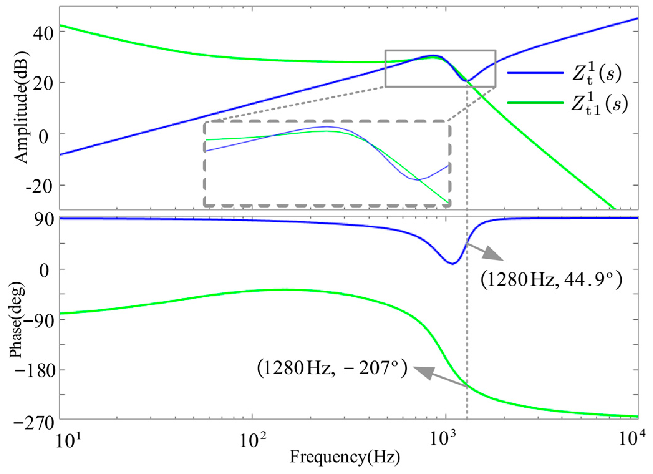
However, as the grid-side line inductance gradually decreases, instability occurs. As shown in Figure 9, when Lg is 3 mH, the crossover frequency between Z t 1 s and Z t 1 1 s reaches up to 1280 Hz. At this frequency, the phases of Z t 1 s and Z t 1 1 s are 44.9° and −207°, respectively, resulting in a phase margin less than zero, which indicates that the control system becomes unstable.

3.4. Improved q-Axis Control Compensation Strategy

Reference [21] indicates that introducing derivative feedback into the control loop can enhance the phase of the system’s open-loop transfer function. In Section 3.3, the phase of Z t 1 1 s in the high-frequency range is excessively low, resulting in a negative phase margin and consequent instability of the control system. This paper adopts the control concept of derivative feedback, however, considering the risk of harmonic amplification.
Associated with a derivative term, the integral transfer function H(s) proposed in Reference [22] is employed as an equivalent substitute. Its specific expression is given by Equation (9) as follows:
H s = k ω c 2 s s 2 + ω s s + ω c 2
In the equation, ωs denotes the cutoff angular frequency, ωc represents the maximum gain angular frequency, and k is the proportional coefficient.
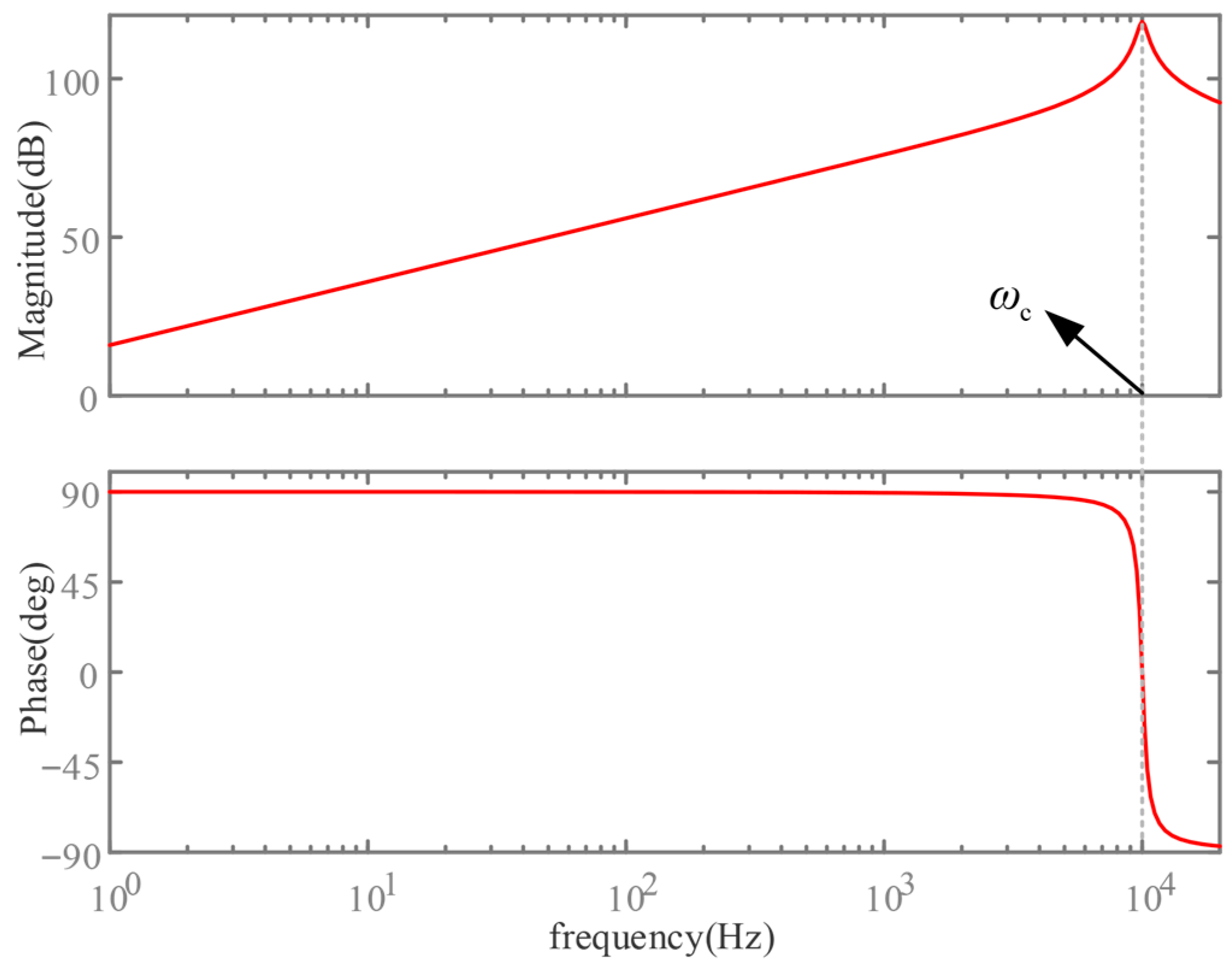
The Bode diagram of H(s) is shown in Figure 10. To ensure that H(s) maintains its derivative characteristics within the Nyquist frequency, ωc should be set to πfs, where fs is the switching frequency. Within this frequency range, H(s) can effectively replace the derivative term. By adjusting ωs, the gain at ωc can be regulated, thereby effectively suppressing noise. After introducing the H(s)-based negative feedback, the control block diagram is as illustrated in Figure 11. At this point, the inverter output impedance and phase margin are given by Equations (10) and (11), respectively.
Z t 1 2 s = T A s / [ G x 2 s + k H s T A s / G i s ] Z t 2 2 s = 1 / [ G x 2 s + k H s T A s / G i s ]
P M 3 = 180 a r g [ Z t 2 ( s ) ] a r g [ Z t 1 2 ( s ) ]
In the equation, Z t 2 s is equal to the sum of Z t 1 2 s and Zg(s).
Under the condition of Lg = 3 mH, Figure 12 compares the effects of different k values on the output impedance. When k = 0.3, the crossover frequency between Z t 2 s and Z t 1 2 s is 1060 Hz, and the phases of Z t 2 s and Z t 1 2 s at the crossover frequency are 41° and −191°, respectively. According to Equation (11), the phase margin is less than zero. When k = 0.5, the crossover frequency is 630 Hz, and the corresponding phases are 49.4° and −111°, giving a phase margin of 19.6°. When k = 0.8, the crossover frequency is 725 Hz, and the corresponding phases are 42.4° and −136°, resulting in a phase margin of 1.6°. It can be observed that as k increases, the crossover frequency of the impedance decreases first and then increases, while the phase margin increases first and then decreases. Therefore, a value of k = 0.5 is chosen as a compromise.
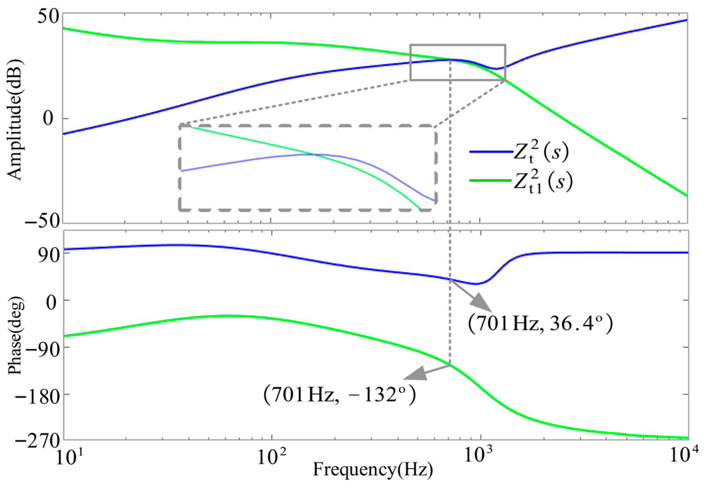
When k = 0.5 and Lg = 3 mH, adopting the improved q-axis control compensation strategy can stabilize the control system and expand the adaptability range of the system to grid impedance. As shown in Figure 13, when the grid impedance is further reduced to 0, the crossover frequency between Z t 2 s and Z t 1 2 s is 701 Hz, and the phases of Z t 2 s and Z t 1 2 s at the crossover frequency are 36.4° and −132°, respectively. At this point, the phase margin is 11.6°, and the control system remains stable. It can be seen that by applying the improved q-axis control compensation strategy, the inverter can operate stably with grid impedance ranging from 0 to 15 mH, significantly enhancing the adaptability of the control system to grid impedance variations.

4. Experimental Validation

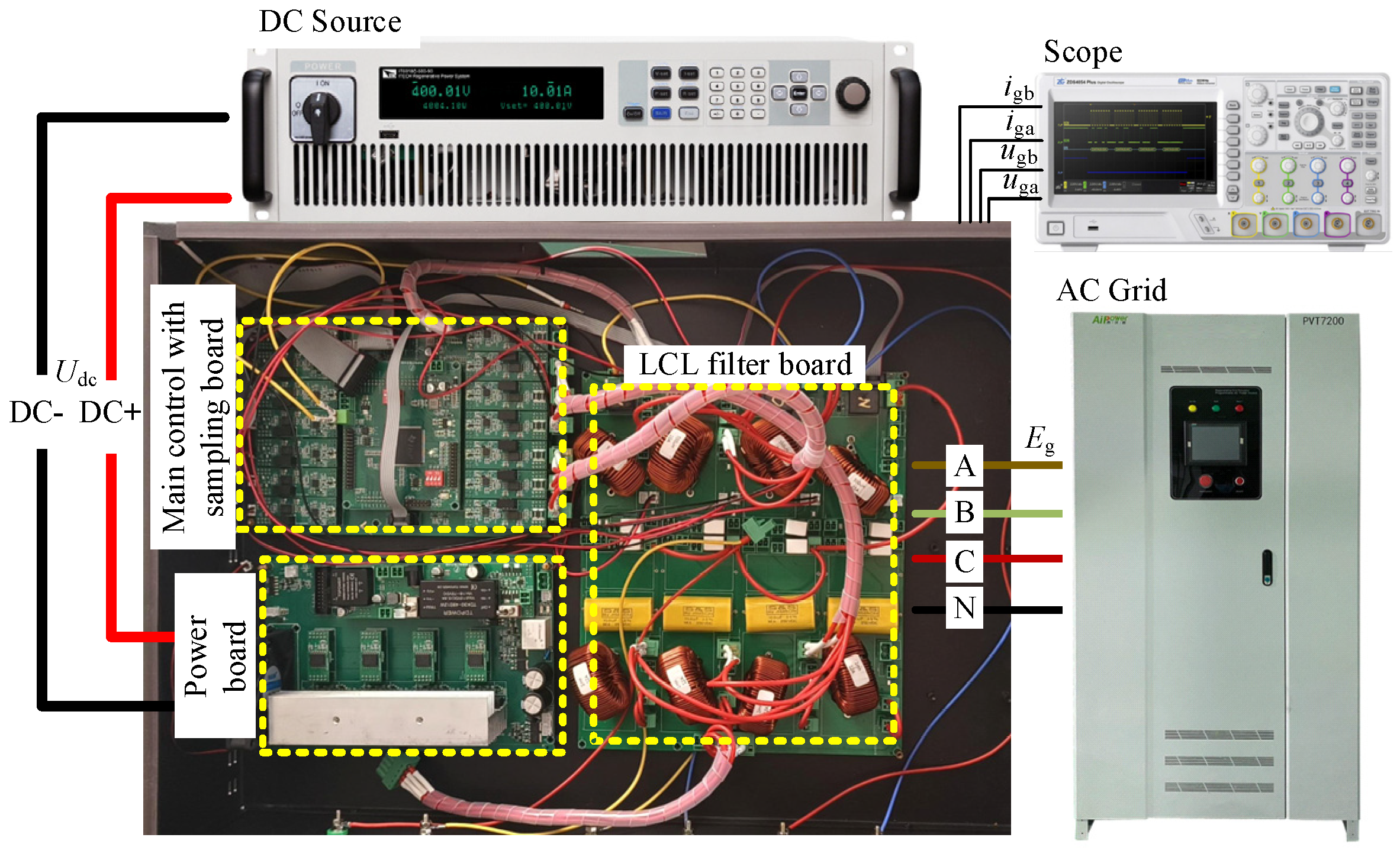
To verify the correctness of the above theoretical analysis, a three-phase grid-connected inverter experimental platform with a rated capacity of 10 kVA was built, as shown in Figure 14. The experimental platform consists of a DC power supply, an oscilloscope, a grid simulator, and a 10 kVA inverter. The inverter includes the main control with a sampling board, a power board, and an LCL filter board. The waveforms of the grid-connected voltage and current are measured using the oscilloscope. The parameters of the experimental platform are listed in Table 1.

4.1. Experimental Comparison Before and After Impedance Criterion Reshaping

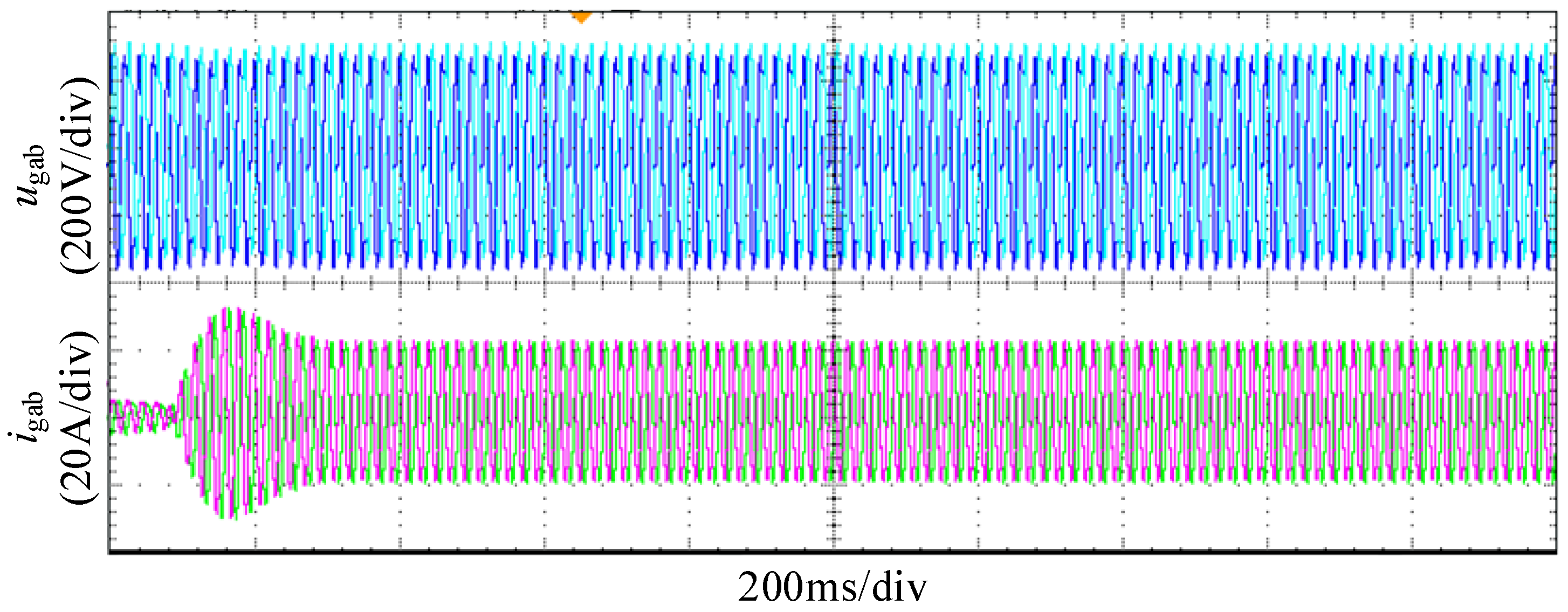
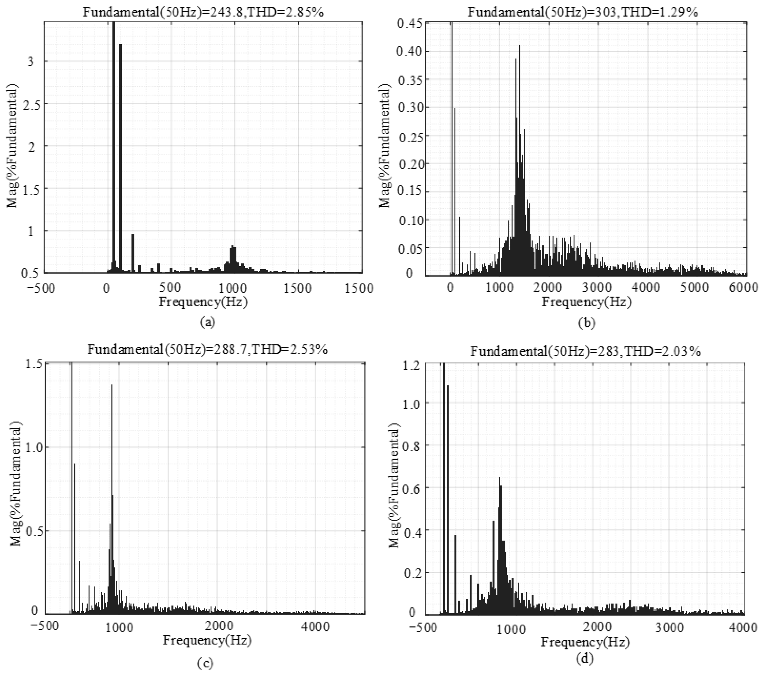
When grid inductance Lg = 15 mH operates without q-axis control compensation, with reference currents set at igdref = 21.4 A and igqref = 0 A, comparative stability analysis in Section 3.2 shows the conventional impedance criterion predicts instability while the proposed reshaped criterion confirms stability. Experimental results in Figure 15 demonstrate stable system operation, with grid-connected current THD measuring 2.85% in Figure 16a, complying with grid standards. This validates the reshaped criterion’s accuracy and reveals the conventional criterion’s stability misjudgment.

4.2. Experimental Analysis of q-Axis Control Compensation Introduction

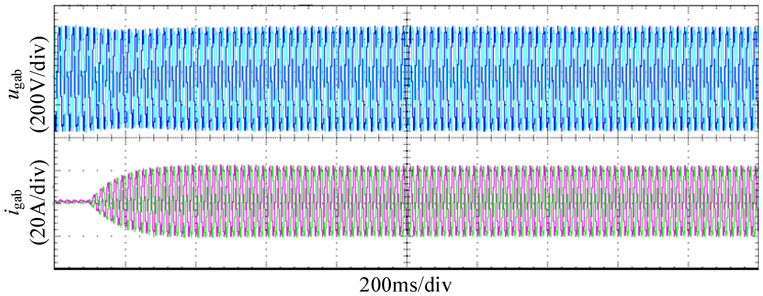
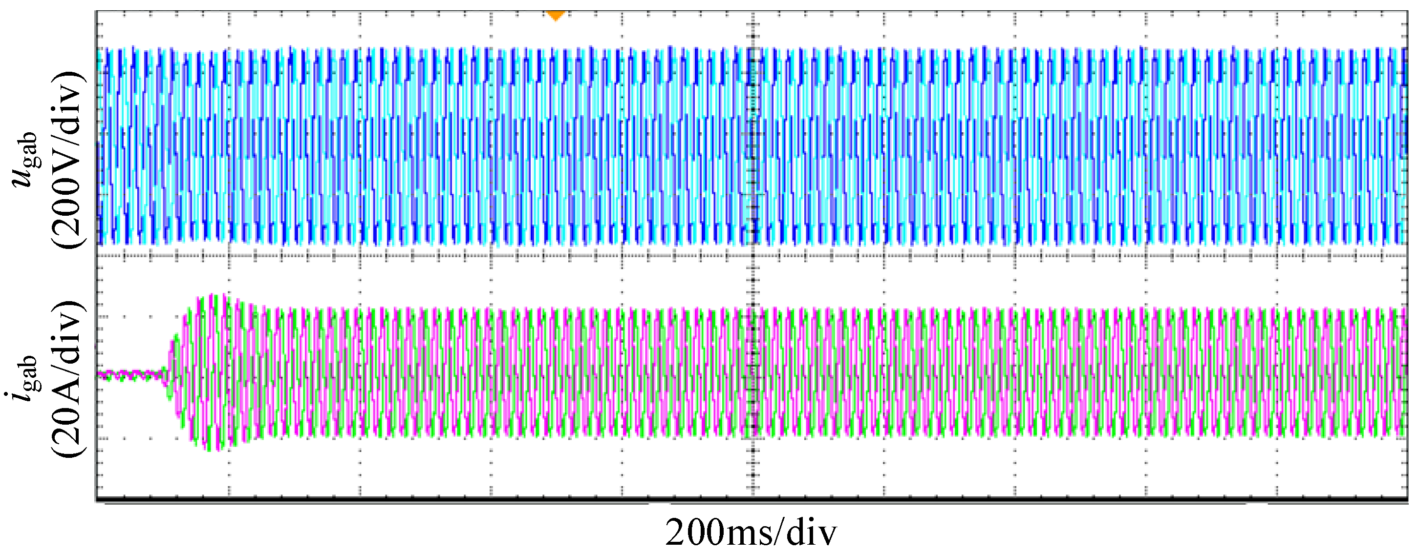
Following the implementation of q-axis control compensation, experiments were conducted under two grid inductance conditions: Lg = 15 mH and Lg = 3 mH, with reference currents set at igdref = 21.4 A and igqref = 0 A. The corresponding grid voltage and current waveforms are presented in Figure 17 and Figure 18, respectively. Analysis of Figure 17 demonstrates that the control system maintains stable operation with Lg = 15 mH under control compensation, where the grid-connected current total harmonic distortion (THD) measures 1.29% as shown in the spectrum in Figure 16b, complying with grid code requirements. However, when the grid inductance decreases to 3 mH, the system exhibits evident oscillatory instability, as shown in Figure 18. These experimental results indicate that after implementing q-axis control compensation, the control system becomes susceptible to instability risks under reduced grid impedance conditions.

4.3. Experimental Analysis of the Improved q-Axis Control Compensation

Under the condition of grid inductance Lg = 3 mH with the improved q-axis control compensation implemented, experimental validation was conducted for three parameter configurations of compensation coefficient k: 0.3, 0.5, and 0.8. The experimental results are shown in Figure 19. The findings demonstrate that: when k = 0.3, the control system becomes unstable; when k = 0.5, the system maintains stable operation with a grid-connected current total harmonic distortion (THD) of 2.53%, whose spectral distribution is shown in Figure 16c, meeting the grid power quality requirements; when k increases to 0.8, the control system again exhibits instability due to insufficient phase margin. The stability performance under different k values is fully consistent with the theoretical analysis presented in Section 3.4.
Under the improved q-axis control compensation parameter (k = 0.5), experiments were conducted under the condition of grid inductance Lg = 0 mH, with reference currents set to igdref = 21.4 A and igqref = 0 A. The experimental results are shown in Figure 20. Observations demonstrate that with the improved control compensation algorithm, the control system maintains stable operation under this condition. The grid-connected current total harmonic distortion (THD) was measured at 2.03%, with its spectral distribution shown in Figure 16d, meeting the grid power quality requirements. These results effectively verify the significant role of the proposed method in enhancing the system’s adaptability to grid impedance variations.
As evidenced by the preceding analysis and experimental results, when the grid impedance Lg varies over a wide range, the admissible ranges of Lg for both conventional and improved compensation control methods are summarized in Table 2. The conventional compensation control can accommodate Lg values from 3 mH to 15 mH, whereas the improved compensation control extends this range to 0–15 mH. This demonstrates that the improved compensation control offers a broader grid impedance adaptability, making it more suitable for practical engineering applications under modern weak grid conditions where grid impedance frequently fluctuates.

5. Conclusions

This paper starts by addressing the issue of errors introduced by traditional impedance criteria in characterizing stability margins and systematically analyzes the causes of inaccuracies in the traditional criterion. Based on the reshaped impedance criterion method, the stability and stability margins of the control system are investigated in depth. The study shows that the PLL generates small-signal disturbances under the influence of grid impedance, which can lead to inverter instability under high-grid-impedance conditions. Although traditional q-axis compensation control can improve the adaptability of the inverter under high grid impedance, instability issues still exist under low-grid-impedance conditions. Based on this, this paper proposes an improved q-axis compensation control strategy and further analyzes the output impedance characteristics of the improved control in conjunction with the reshaped impedance criterion. The main conclusions are as follows:
(1)
The reshaped impedance criterion method can accurately characterize the actual phase margin of the control system, effectively resolving the phase error inherent in traditional impedance criteria, and provides a more precise tool for stability analysis in practical applications. This method significantly enhances the accuracy of system stability assessments, especially in areas where grid impedance varies significantly.
(2)
The proposed improved q-axis compensation control not only enhances the adaptability of the inverter under high-line-impedance conditions but also addresses the instability problem under low-line-impedance conditions, thereby significantly expanding the adaptability range of the grid impedance. In addition, the impedance model established based on the reshaped impedance criterion can accurately reflect the actual phase margin of the system, completely avoiding the characterization errors of traditional methods.
(3)
The method proposed in this study has great potential for practical engineering applications. By improving the inverter control strategy, it can effectively enhance stability under various grid conditions and provide strong support for the optimization of renewable energy grid integration systems. It also offers technical guarantees for the construction of smart grids and future power systems.

Author Contributions

Conceptualization, H.M. and X.Y.; Methodology, H.M. and X.Y.; Software, H.M.; Validation, H.M.; Formal analysis, H.M. and X.Y.; Investigation, H.M. and X.Y.; Resources, X.Y.; Data curation, H.M.; Writing—original draft, H.M.; Writing—review & editing, H.M. and X.Y.; Visualization, H.M. and X.Y.; Supervision, X.Y.; Project administration, H.M. and X.Y.; Funding acquisition, X.Y. All authors have read and agreed to the published version of the manuscript.

Funding

This research received no external funding.

Data Availability Statement

The original contributions presented in this study are included in the article. Further inquiries can be directed to the corresponding author.

Conflicts of Interest

The authors declare no conflict of interest.

References

  1. Wilk-Jakubowski, J.L.; Pawlik, L.; Wilk-Jakubowski, G.; Harabin, R. State-of-the-Art in the Use of Renewable Energy Sources on the Example of Wind, Wave Energy, Tidal Energy, and Energy Harvesting: A Review from 2015 to 2024. Energies 2025, 18, 1356. [Google Scholar] [CrossRef]
  2. Azam, M.A.; Khan, M.R.; Saeed, A. A Review of Sustainable Energy Sources Using Machine Learning. Energies 2023, 16, 6236. [Google Scholar]
  3. Mimouni, A.; Laribi, S.; Bizhani, H.; Iwanski, G. Switch Fault Diagnosis of Grid-Connected Inverter Using Symmetrical Components. IEEE J. Emerg. Sel. Top. Power Electron. 2024, 12, 5258–5272. [Google Scholar] [CrossRef]
  4. Pang, Y.; Li, Y.; Zhang, J.; Yang, H.; Ji, Y.; Zhang, X.; Zhu, Y.; Li, G.; Xiang, Z.; Gong, C.; et al. A Multiple Energy Conversion Channels Fusion Grid-Connected Inverter for Large-Scale PV Active Power Injection Preventing Power Loss Caused by Insufficient MPP PV Voltage. IEEE Trans. Power Electron. 2025, 40, 13415–13433. [Google Scholar] [CrossRef]
  5. Malkhandi, A.; Senroy, N.; Mishra, S. A Dynamic Model of Impedance for Online Thevenin’s Equivalent Estimation. IEEE Trans. Circuits Syst. II Express Briefs 2022, 69, 194–198. [Google Scholar] [CrossRef]
  6. Jin, Z.; Wang, X. A DQ-Frame Asymmetrical Virtual Impedance Control for Enhancing Transient Stability of Grid-Forming Inverters. IEEE Trans. Power Electron. 2022, 37, 4535–4544. [Google Scholar] [CrossRef]
  7. Wang, Y.; Wang, X.; Blaabjerg, F.; Chen, Z. Harmonic Instability Assessment Using State-Space Modeling and Participation Analysis in Inverter-Fed Power Systems. IEEE Trans. Ind. Electron. 2017, 64, 806–816. [Google Scholar] [CrossRef]
  8. Cai, Y.; He, Y.; Zhang, H.; Zhou, H.; Liu, J. Research on Harmonic State-Space Modeling and Calculation Analysis of Low-Switching-Frequency Grid-Connected Inverter Considering the Impact of Digitization. IEEE Trans. Power Electron. 2023, 38, 1003–1021. [Google Scholar] [CrossRef]
  9. Li, Z.; Li, H.; Sun, S. Virtual Model Predictive Control for Inverters to Achieve Flexible Output Impedance Shaping in Harmonic Interactions With Weak Grids. IEEE Trans. Power Electron. 2024, 39, 10754–10767. [Google Scholar] [CrossRef]
  10. Qian, Q.; Xie, S.; Xu, J.; Xu, K.; Bian, S.; Zhong, N. Output Impedance Modeling of Single-Phase Grid-Tied Inverters With Capturing the Frequency-Coupling Effect of PLL. IEEE Trans. Power Electron. 2020, 35, 5479–5495. [Google Scholar] [CrossRef]
  11. Gao, J.Y.; Zhao, J.B.; Chen, X.B.; Qu, K. Reshaped Impedance-Based Stability Criterion Under Weak Grid Conditions. Power Syst. Technol. 2017, 41, 2762–2768. (In Chinese) [Google Scholar]
  12. Zhu, D.H.; Zhou, S.Y.; Zou, X.D.; Kang, Y. Improved Design of PLL Controller for LCL-Type Grid-Connected Converter in Weak Grid. IEEE Trans. Power Electron. 2020, 35, 4715–4727. [Google Scholar] [CrossRef]
  13. Gao, J.Y.; Xiao, F.; Jiang, F.; Guo, Q.; Lu, B.H. Grid-Connected Inverter Impedance Phase Reshaping Control With Novel PLL Structure in Weak Grid. Proc. CSEE 2020, 40, 6682–6694. (In Chinese) [Google Scholar]
  14. Karimi-Ghartemani, M.; Karimi, H.; Khajehoddin, S.A.; Hoseinizadeh, S.M. Efficient Modeling and Systematic Design of Enhanced Phase-Locked Loop Structures. IEEE Trans. Power Electron. 2022, 37, 9061–9072. [Google Scholar] [CrossRef]
  15. Yang, D.; Ruan, X.; Wu, H. A Virtual Impedance Method to Improve the Performance of LCL-Type Grid-Connected Inverters Under Weak Grid Conditions. Proc. CSEE 2014, 34, 2327–2335. (In Chinese) [Google Scholar]
  16. Lin, X.; Liang, Z.; Zheng, Y.; Lin, Y.; Kang, Y. A Current Limiting Strategy with Parallel Virtual Impedance for Three-Phase Three-Leg Inverter Under Asymmetrical Short-Circuit Fault to Improve the Controllable Capability of Fault Currents. IEEE Trans. Power Electron. 2019, 34, 8138–8149. [Google Scholar] [CrossRef]
  17. Zhu, D.H.; Zhou, S.Y.; Zou, X.D.; Kang, Y.; Zou, K. Small-Signal Disturbance Compensation Control for LCL-Type Grid-Connected Converter in Weak Grid. IEEE Trans. Ind. Appl. 2020, 56, 2852–2861. [Google Scholar] [CrossRef]
  18. Wen, B.; Boroyevich, D.; Burgos, R.; Mattavelli, P.; Shen, Z. Analysis of D-Q Small-Signal Impedance of Grid-Tied Inverters. IEEE Trans. Power Electron. 2016, 31, 675–687. [Google Scholar] [CrossRef]
  19. Tu, C.M.; Gao, J.Y.; Xiao, F.; Guo, Q.; Jiang, F. Stability Analysis of the Grid-Connected Inverter Considering the Asymmetric Positive Feedback Loops Introduced by the PLL in Weak Grids. IEEE Trans. Ind. Electron. 2022, 69, 5793–5802. [Google Scholar] [CrossRef]
  20. Zhou, S.; Zou, X.; Zhu, D.; Tong, L.; Zhao, Y.; Kang, Y.; Yuan, X. An Improved Design of Current Controller for LCL-Type Grid-Connected Converter to Reduce Negative Effect of PLL in Weak Grid. IEEE J. Emerg. Sel. Top. Power Electron. 2018, 6, 648–663. [Google Scholar] [CrossRef]
  21. Yu, H.; Su, J.; Zheng, L.; Zhang, T.; Zhang, D.; Shi, Y. Mechanism Analysis and Suppression Method of Sub-Synchronous Resonance for Energy Storage Inverter Connected to Grid. Autom. Electr. Power Syst. 2020, 44, 99–108. (In Chinese) [Google Scholar]
  22. Xin, Z.; Loh, P.C.; Wang, X.; Blaabjerg, F.; Tang, Y. Highly Accurate Derivatives for LCL-Filtered Grid Converter with Capacitor Voltage Active Damping. IEEE Trans. Power Electron. 2016, 31, 3612–3625. [Google Scholar] [CrossRef]
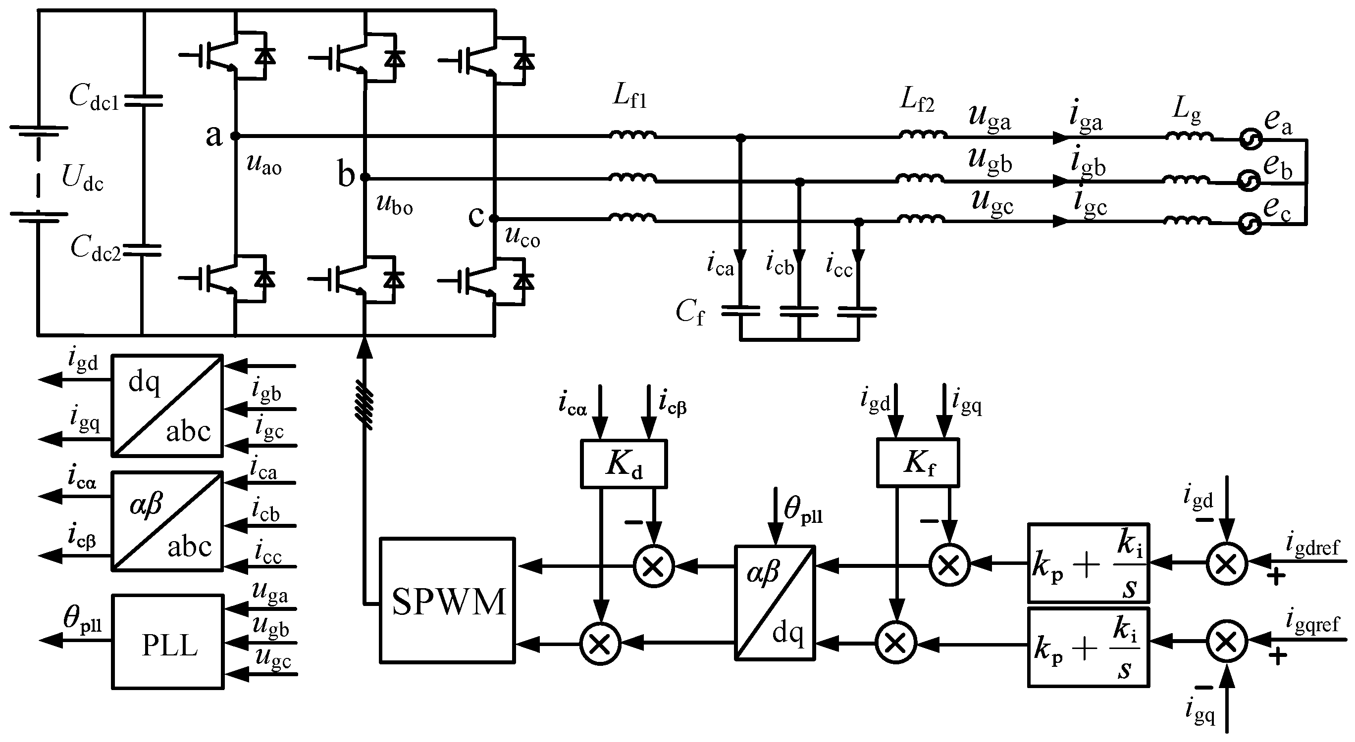
Figure 1. Inverter main circuit model and control system.
Electronics 14 04402 g001
Figure 2. Closed-loop small-signal equivalent model of the DQ-axis of grid-connected inverter: (a) d-axis. (b) q-axis.
Electronics 14 04402 g002
Figure 3. Equivalent model of grid-connected inverter.
Electronics 14 04402 g003
Figure 4. Reconstructs the equivalent model of the impedance criterion for grid-connected inverters.
Electronics 14 04402 g004
Figure 5. Impedance reshaping criterion when Lg is 15 mH.
Electronics 14 04402 g005
Figure 6. Traditional impedance criterion when Lg is 15 mH.
Electronics 14 04402 g006
Figure 7. Disturbance feedback compensation introduced on the q-axis.
Electronics 14 04402 g007
Figure 8. Bode plot of output impedance before and after compensation on the q-axis.
Electronics 14 04402 g008
Figure 9. Bode plot of inverter output impedance when Lg is 3 mH.
Electronics 14 04402 g009
Figure 10. Bode plot of H(s) with k = 1.
Electronics 14 04402 g010
Figure 11. Q-axis improved control compensation strategy.
Electronics 14 04402 g011
Figure 12. Bode plot of output impedance at different k values: (a) Overall Schematic Diagram. (b) Locally Enlarged View from 200 Hz to 1400 Hz.
Electronics 14 04402 g012
Figure 13. Bode plot of output impedance with improved control compensation when Lg is 0.
Electronics 14 04402 g013
Figure 14. 10 kVA experimental platform.
Electronics 14 04402 g014
Figure 15. Grid-connected voltage and current without control compensation when Lg is 15 mH.
Electronics 14 04402 g015
Figure 16. Grid-connected current THD: (a) Lg = 15 mH without control compensation. (b) Lg = 15 mH with conventional control compensation. (c) Lg = 3 mH with improved control compensation. (d) Lg = 0 mH with improved control compensation.
Electronics 14 04402 g016
Figure 17. Grid-connected voltage and current with control compensation when Lg is 15 mH.
Electronics 14 04402 g017
Figure 18. Grid-connected voltage and current with control compensation when Lg is 3 mH.
Electronics 14 04402 g018
Figure 19. Influence of k on Stability.
Electronics 14 04402 g019
Figure 20. Grid-connected voltage and current with improved control compensation when Lg is 0.
Electronics 14 04402 g020
Table 1. Key system parameters.
ParameterSymbolValue
DC VoltageUdc700 V
Grid VoltageEg311 V
Rated CapacitySn10 kVA
Filter Inductance1Lf13 mH
Filter Inductor2Lf20.8 mH
Filter CapacitorCf15 uF
Switching Frequencyfs10 kHz
Active Damping CoefficientKd13
Proportional Coefficient of the Current Loopkp2
Integral Coefficient of the
Current Loop
ki350
Proportional Coefficient of PLLkppll0.8
Integral Coefficient of PLLkipll32
Proportional Coefficientk0.5
Cutoff Angular Frequency ω s 5000 rad/s
Maximum Gain Angular
Frequency
ω c 104π rad/s
Table 2. Stable operating range for Lg.
Control MethodStable Operating Range for Lg
Traditional compensation control3–15 mH
Improved compensation control0–15 mH
Disclaimer/Publisher’s Note: The statements, opinions and data contained in all publications are solely those of the individual author(s) and contributor(s) and not of MDPI and/or the editor(s). MDPI and/or the editor(s) disclaim responsibility for any injury to people or property resulting from any ideas, methods, instructions or products referred to in the content.