You are currently viewing a new version of our website. To view the old version click .
Electronics
  • Article
  • Open Access

10 November 2025

An Adaptive Observer-Based Voltage Parameter Estimation Method for Single-Phase Grid with DC Offset

,
,
,
and
1
Marketing Service Center of State Grid Chongqing Electric Power Company, Chongqing 400015, China
2
School of Mechano-Electronic Engineering, Xidian University, Xi’an 710071, China
*
Author to whom correspondence should be addressed.
This article belongs to the Special Issue New Trends in Power Electronics for Renewable Energy and Power Systems

Abstract

In this paper, a novel adaptive observer is proposed to estimate the parameters of single-phase voltage signals that contain a DC offset. A state-space model of the voltage signal with DC offset is first derived and shown to be observable. To eliminate steady-state estimation errors caused by DC offsets, an observer is designed to estimate the AC in-phase component, its quadrature component, and the DC offset in real time. Although the observer design initially assumes a known grid frequency, an auxiliary frequency estimator is subsequently coupled with the observer to update the frequency estimate online. Voltage amplitude and phase are obtained from the estimated in-phase and quadrature components. Lyapunov-based analysis is used to establish the stability and convergence of the proposed scheme. Experimental results demonstrate the method’s accuracy and robustness in the presence of DC offsets.

1. Introduction

The integration of renewable energy sources, such as wind and solar power, has been increasing in recent years []. However, this growth introduces significant challenges for grid-connected distributed generation (GCDG) systems. Renewable energy sources can introduce disturbances into the power grid, such as DC offsets and high-order harmonics [,]. These disturbances can adversely affect the accurate estimation of grid voltage, frequency, and phase, which are essential for the reliable operation of grid-connected converters. Therefore, developing a DC-offset-free parameter estimation method is crucial for maintaining the efficiency and safety of power-grid operations [,].
Over the years, various methods have been proposed for single-phase grid parameter estimation. Among them, Fourier-transform-based techniques, including the Discrete Fourier Transform (DFT) and Fast Fourier Transform (FFT), are widely used for voltage estimation in power grids [,,,]. However, these methods suffer from inherent limitations. Spectral leakage occurs when signal frequencies do not align with the DFT/FFT bins. The resulting energy spread degrades amplitude and frequency estimates used in power-system analysis [,,]. In such cases, the signal’s energy spreads across multiple frequency bins, leading to inaccuracies in voltage parameter estimation and potentially degrading the performance of grid-connected systems []. Furthermore, Fourier-transform-based methods typically involve high computational costs, making real-time implementation challenging and thereby limiting their applicability in modern power systems.
Phase-Locked Loops (PLLs) are another widely adopted technique for voltage estimation [,]. In single-phase systems, PLLs employ Orthogonal Signal Generators (OSGs) to provide the required orthogonal components, as only one input signal is available []. Various OSGs have been proposed, with the second-order generalized integrator (SOGI) being one of the most prominent []. Furthermore, several advanced PLLs have been developed, such as the complex-coefficient filter PLL (CCF-PLL), which effectively eliminates negative frequency components [], the DC offset error compensation PLL (DOEC-PLL) [], and the variable time-delay PLL (VTD-PLL), designed for fast transient response [].
While advanced OSG-based PLLs can effectively suppress DC and high-frequency harmonic components, they often lead to increased system complexity and reduced dynamic performance. Conversely, simpler OSG-based approaches reduce computational load but provide less effective filtering. As a result, achieving an optimal balance between dynamic response, filtering capability, and computational efficiency in PLL design remains a challenge.
A comparison of different voltage parameter estimation methods is shown in Table 1. To address the limitations of conventional methods, this paper proposes a novel adaptive observer for real-time voltage parameter estimation. The method eliminates the need for OSGs and features a fast dynamic response. Initially, the grid frequency is treated as a known parameter, enabling the observer to estimate the AC component, its orthogonal signal, and the DC offset in real time. An auxiliary frequency estimator operates alongside the observer to update the grid frequency online. The voltage amplitude and phase are then derived from the estimated in-phase and orthogonal components. The stability of the proposed observer is proven through Lyapunov analysis. Experimental results verify its effectiveness, demonstrating high accuracy and rapid dynamic performance. However, the current method does not fully address strong harmonic interference and rapid amplitude variations. Future work will enhance robustness by extending the observer to multi-harmonic and amplitude-adaptive schemes.
Table 1. Comparison of voltage parameter estimation methods.
The main contributions of this paper are as follows:
  • A novel adaptive observer is proposed that achieves a rapid dynamic response.
  • The method enables accurate voltage parameter estimation in the presence of DC offsets, thereby eliminating steady-state errors commonly encountered in conventional techniques.

2. Proposed Adaptive Observer

Consider a single-phase grid voltage with a DC offset:
u = V s i n ( ω t + ϕ ) + V d c
where V, ω , ϕ , and V d c represent amplitude, frequency, phase, and DC offset, respectively.
To build the adaptive observer, the following state vector is introduced:
x = V s i n ( ω t + ϕ ) V c o s ( ω t + ϕ ) V d c T
Hence, the state equation of the system is given by:
x ˙ = A ¯ x u = C ¯ x
With A ¯ = 0 ω 0 ω 0 0 0 0 0 and C ¯ = [ 1 , 0 , 1 ]
It is evident that rank C ¯ C ¯ A ¯ C ¯ A ¯ 2 T = 3 , implying that the system (3) is observable. Nevertheless, the unknown grid frequency ω restricts the applicability of conventional state observers that assume known model parameters. To overcome this limitation, we design an adaptive observer that jointly estimates the system state and the unknown frequency online.

2.1. Proposed Adaptive Observer Design

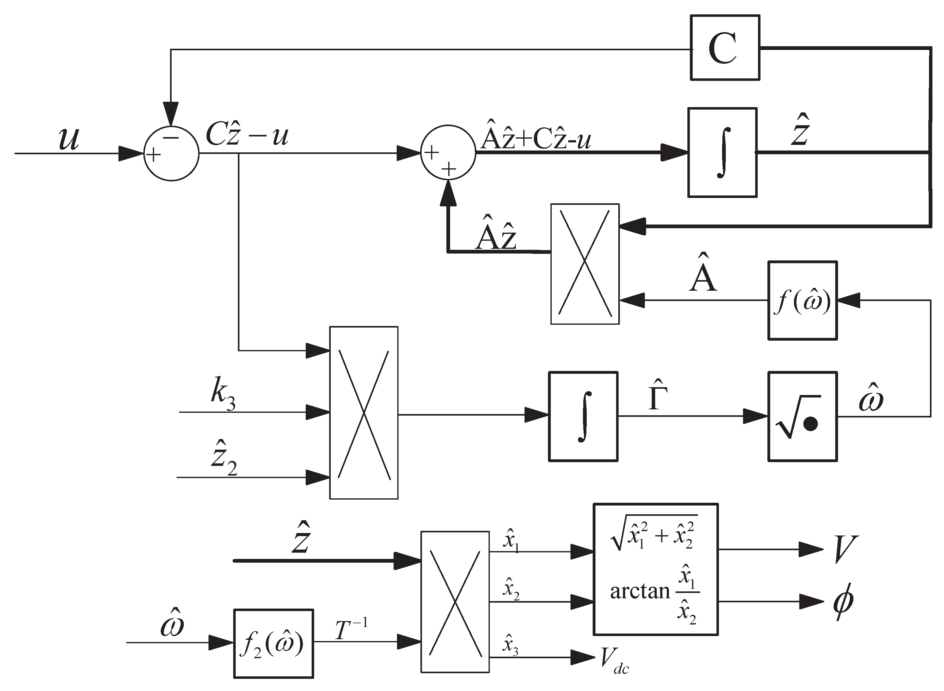
In order to address the issue described above, this section proposes a novel adaptive observer. First, a new vector z is introduced and an adaptive observer is constructed using this vector and the voltage signal u. The observer output is then used to compute the state vector x and the grid frequency ω . Finally, the amplitude and phase are determined from the state vector x. The structure of the proposed adaptive observer is shown in Figure 1. Specifically, the new vector z is defined to satisfy the following relation with x:
x = T z = 0 0 k 2 k 1 w 2 0 k 1 k 2 w 2 w 0 k 1 0 k 1 w 2 z
where k 1 , k 2 are design parameters, T is a nonsingular matrix.
Figure 1. Structure Block Diagram of the proposed adaptive observer.
Under this transformation the system becomes
z ˙ = A z = T 1 A ¯ T z u = C z = C ¯ T z
with:
A = 0 1 0 0 0 1 0 Γ 0 C = k 1 0 k 2 Γ = ω 2
The proposed adaptive observer for the transformed system is defined as
z ^ ˙ = A ^ z ^ + L ( C z ^ u ) Γ ^ ˙ = k 3 z ^ 2 ( C z ^ u )
where k 3 is a design parameter, z ^ , A ^ are the estimation of z , A and
A ^ = 0 1 0 0 0 1 0 Γ ^ 0 L = 0 0 1 Γ ^ = ω ^ 2
Once the estimates z ^ and Γ ^ have been obtained, the state vector x and grid frequency ω are calculated as follows:
x ^ = T ^ z ^ ω ^ = Γ ^
where:
T ^ = 0 0 k 2 k 1 w ^ 2 0 k 1 k 2 w ^ 2 w ^ 0 k 1 0 k 1 w ^ 2
Additionally, the voltage amplitude and phase are obtained from x ^
V ^ = x ^ 1 2 + x ^ 2 2 ϕ ^ = arctan x ^ 1 x ^ 2

2.2. Stability Analysis

In this section, the stability of the proposed adaptive observer is analysis by the Lyapunov stability theorem and LaSalle’s invariance principle.
Define the estimation errors
z ˜ = z ^ z Γ ˜ = Γ ^ Γ
By Equation (7), the dynamic of the estimation error is:
z ˜ ˙ = z ^ ˙ z ˙ = A ^ z ^ A z + L C ( z ^ z ) = ( A + L C ) z ˜ B z ^ 2 Γ ˜ = A l c z ˜ B z ^ 2 Γ ˜ Γ ˜ ˙ = Γ ^ ˙ Γ ˙ = k 3 z ^ 2 ( C z ^ u )
where B = 0 0 1 T ,   A l c = 0 1 0 0 0 1 k 1 Γ k 2
Assume k 2 Γ k 1 > 0 . Then all eigenvalues of A l c have negative real parts, and hence A l c is Hurwitz. Moreover, for s = j ω it holds that
R e ( C ( s I A l c ) 1 B ) = R e ( k 1 + k 2 s 2 s 3 + k 2 s 2 + Γ s + k 1 ) > 0
Therefore, by the Kalman–Yakubovich–Popov (KYP) lemma there exist symmetric positive-definite matrices P and Q such that
A l c T P + P A l c = Q P B = C
Choose the Lyapunov function:
U ( z ˜ , Γ ˜ ) = z ˜ T P z ˜ + Γ ˜ 2 k 3
Its time derivative along the error dynamics is
U ˙ ( z ˜ , Γ ˜ ) = z ˜ T ( A l c T P + P A ) z ˜ 2 z ^ 2 Γ ˜ z ˜ T P B + 2 Γ ˜ ( Γ ^ ˙ Γ ˙ ) k 3 = z ˜ T Q z ˜ 2 z ^ 2 Γ ˜ z ˜ T C T + 2 Γ ˜ z ^ 2 ( C z ^ u ) = z ˜ T Q z ˜ 0
Hence, the system is Lyapunov stable.
Apply LaSalle’s invariance principle to establish asymptotic convergence. On the largest invariant set where U ˙ 0 , it holds that z ˜ = 0 . Substituting this into the error dynamics (Equation (12)) yields
z ^ 2 Γ ˜ = 0 Γ ˜ ˙ = 0
By Equation (4), z can be calculated as:
z = T 1 x = 1 k 2 ω 2 0 1 k 1 0 ω k 1 k 2 ω 2 0 ω 2 k 2 ω 2 k 1 0 0 x
Therefore:
z 2 = ω x 2 k 1 k 2 ω 2 = ω V c o s ( ω t + ϕ ) k 1 k 2 ω 2
Since z ^ 2 converges to z 2 , which is not identically zero. Combining this with the relations above, the only invariant point is ( z ˜ , Γ ˜ ) = ( 0 , 0 ) .
In summary, under the assumption k 2 Γ k 1 > 0 , the proposed adaptive observer satisfy:
lim t z ˜ = lim t ( z ^ z ) = 0 lim t Γ ˜ = lim t ( Γ ^ Γ ) = 0

3. Experimental Results

In this section, the effectiveness and performance of the proposed direction method are further evaluated through experiments. The proposed method is implemented on the YXSPACE-SP2000 processing platform, operating at a frequency of 50 kHz. The parameters of the proposed method are selected as k 1 = 6 × 10 6 , k 2 = 7 × 10 2 , k 3 = 7 × 10 12 . The following five scenarios as shown in Table 2 are provided to show the performance of the proposed method:
Table 2. Experiment conditions.
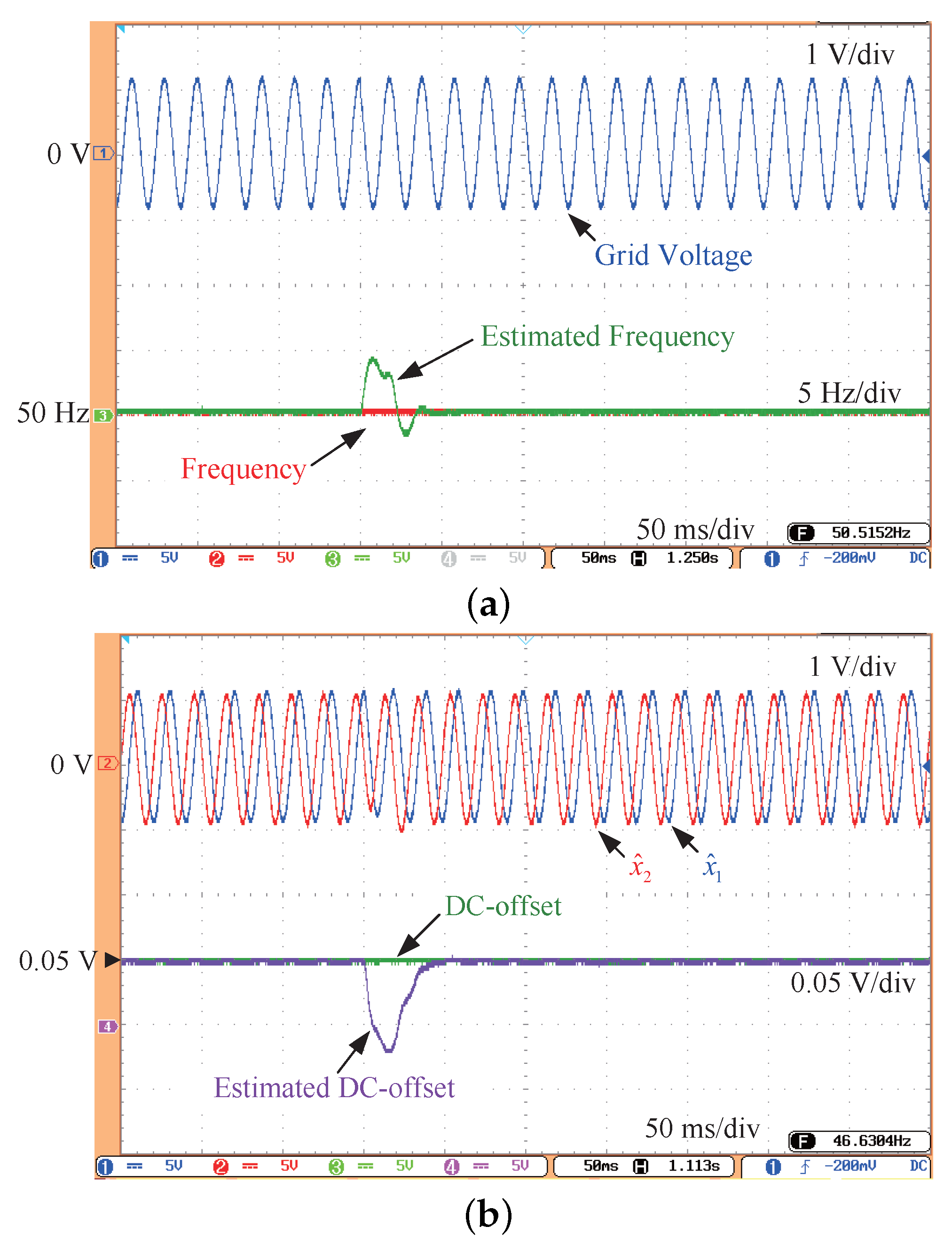
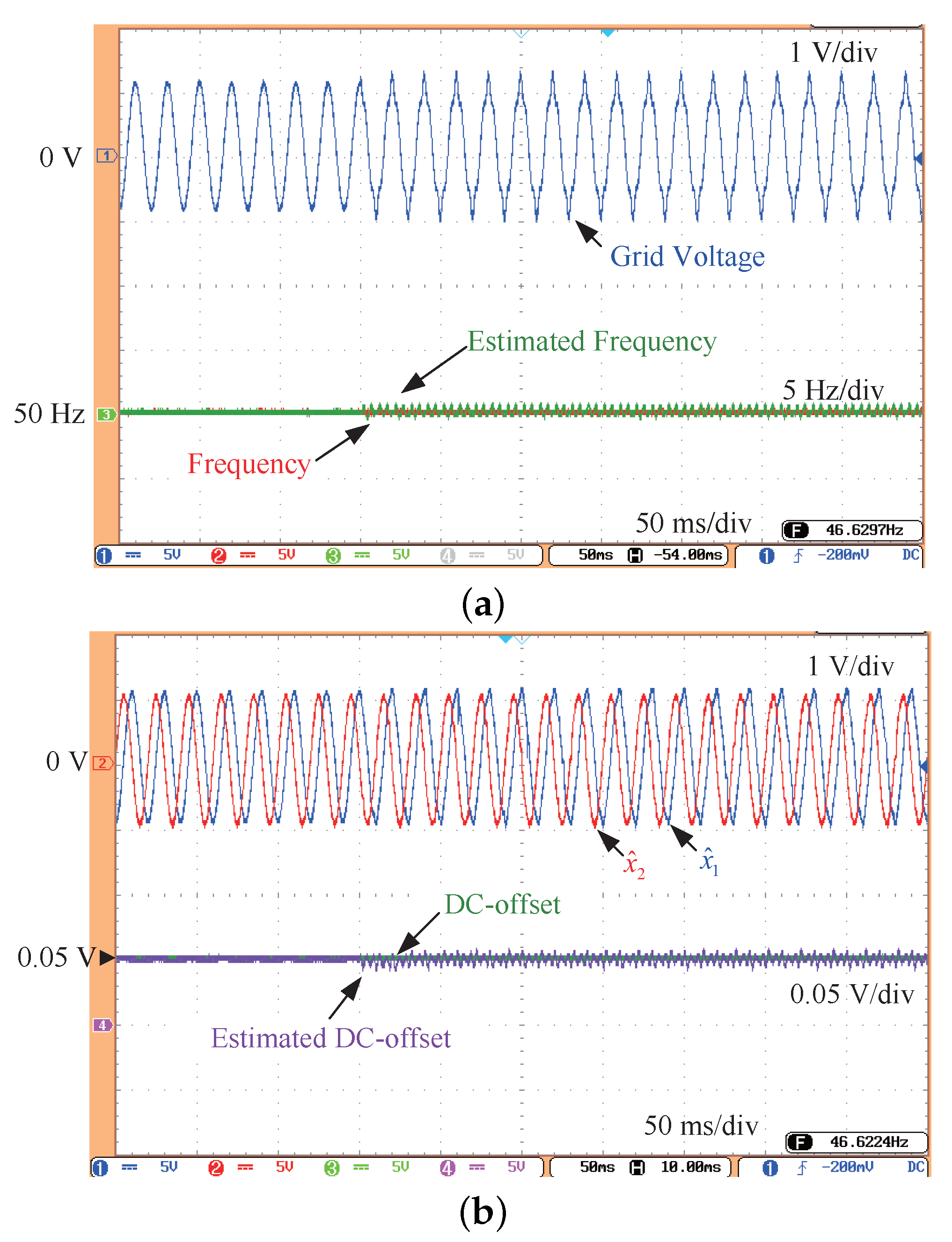
Case A: As shown in Figure 2a same as Figure 3 and Figure 4, the grid voltage contains a 0.05 p . u . DC offset and undergoes a phase jump of π / 6 . The waveforms of the grid frequency and the estimated frequency exhibit a rapid dynamic response within 50 ms . The corresponding waveforms for the DC offset, estimated sinusoidal component x ^ 1 , orthogonal sinusoidal component x ^ 2 , and estimated DC offset x ^ 3 are presented in Figure 2b. These waveforms demonstrate excellent dynamic performance and zero steady-state error. This set of experiments validates the effectiveness of the proposed method in handling DC offset and small phase jumps.
Figure 2. Experimental result under Case A. (a) The grid voltage, frequency, and estimated frequency. (b) x ^ 1 , x ^ 2 , DC-offset and estimated DC offset.
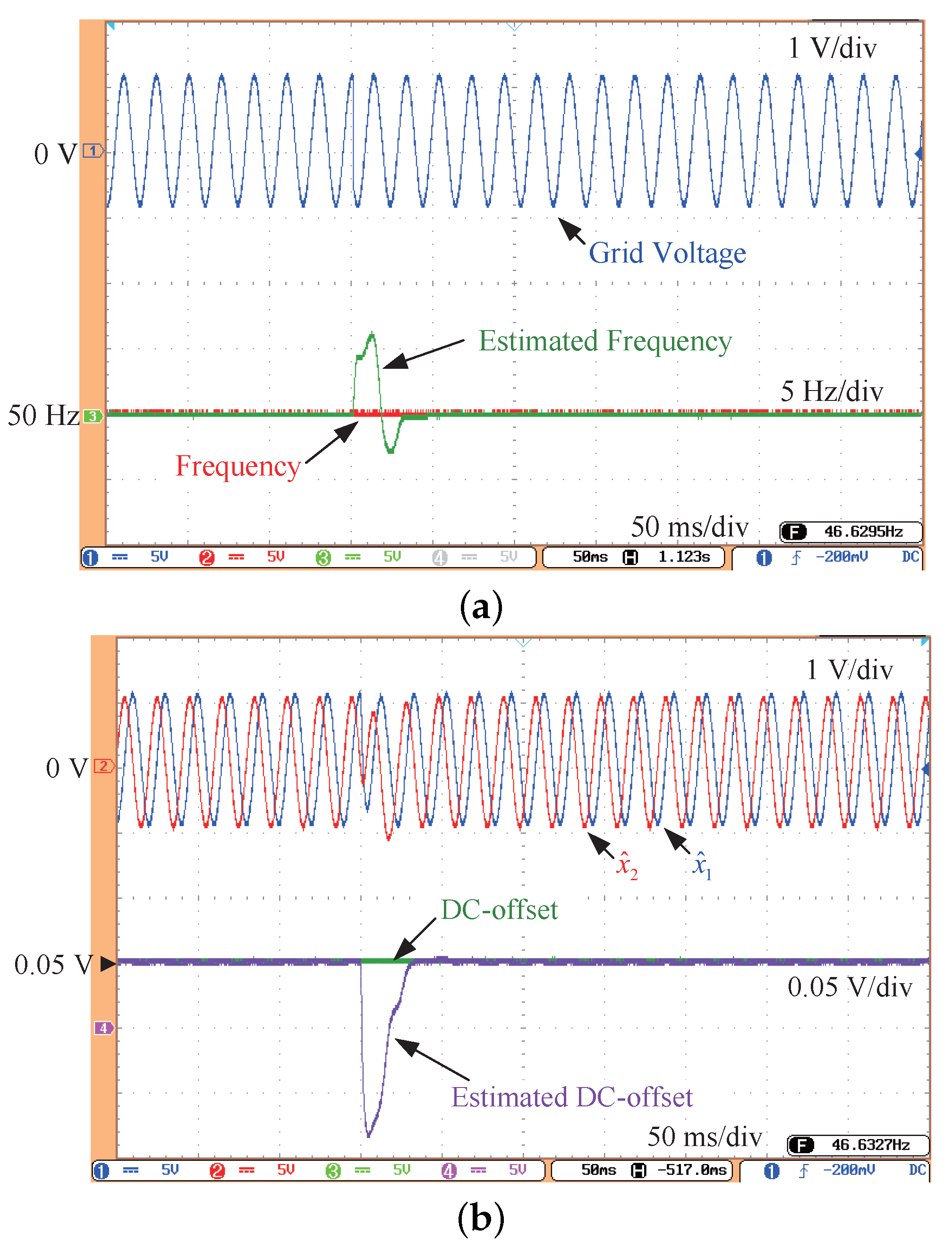
Figure 3. Experimental result under Case B. (a) The grid voltage, frequency, and estimated frequency. (b) x ^ 1 , x ^ 2 , DC-offset and estimated DC offset.
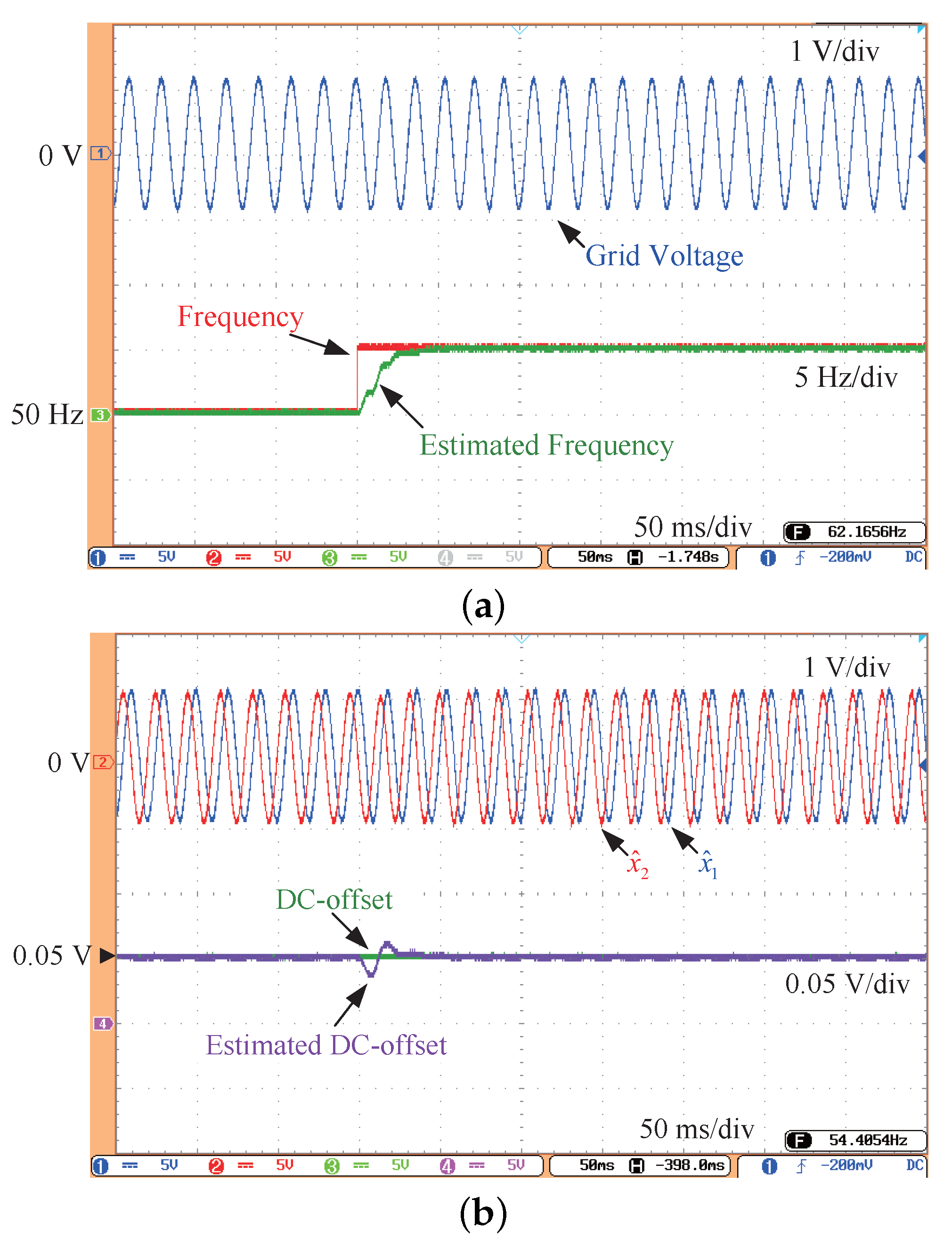
Figure 4. Experimental result under Case C. (a) The grid voltage, frequency, and estimated frequency. (b) x ^ 1 , x ^ 2 , DC-offset and estimated DC offset.
Case B: As illustrated in Figure 3a, the grid voltage contains a 0.05 p . u . DC offset and experiences a large phase jump of 2 π / 3 . The waveforms of both the grid frequency and the estimated frequency demonstrate that the proposed method maintains a rapid dynamic response within 50 ms , even in the presence of a large phase jump. Figure 3b presents the corresponding waveforms for the DC offset, estimated sinusoidal component x ^ 1 , orthogonal sinusoidal component x ^ 2 , and estimated DC offset x ^ 3 . These waveforms show that, despite the significant departure in the estimated values, they converge to the actual values within 50 ms . Case B validates the dynamic and steady-state performance of the method under conditions of DC offset and large phase jump.
Case C: As depicted in Figure 4a, the grid voltage contains a 0.05 p . u . DC offset and experiences a frequency jump of 5 Hz . The estimated frequency waveforms quickly converge to the true value without significant overshoot. Figure 4b presents the waveforms for the DC offset, estimated sinusoidal component x ^ 1 , orthogonal sinusoidal component x ^ 2 , and estimated DC offset x ^ 3 . These waveforms illustrate that, despite minor deviations from the actual values, the estimates rapidly converge with minimal departure. Case C further validates the dynamic and steady-state performance of the proposed method under conditions of DC offset and frequency jump.
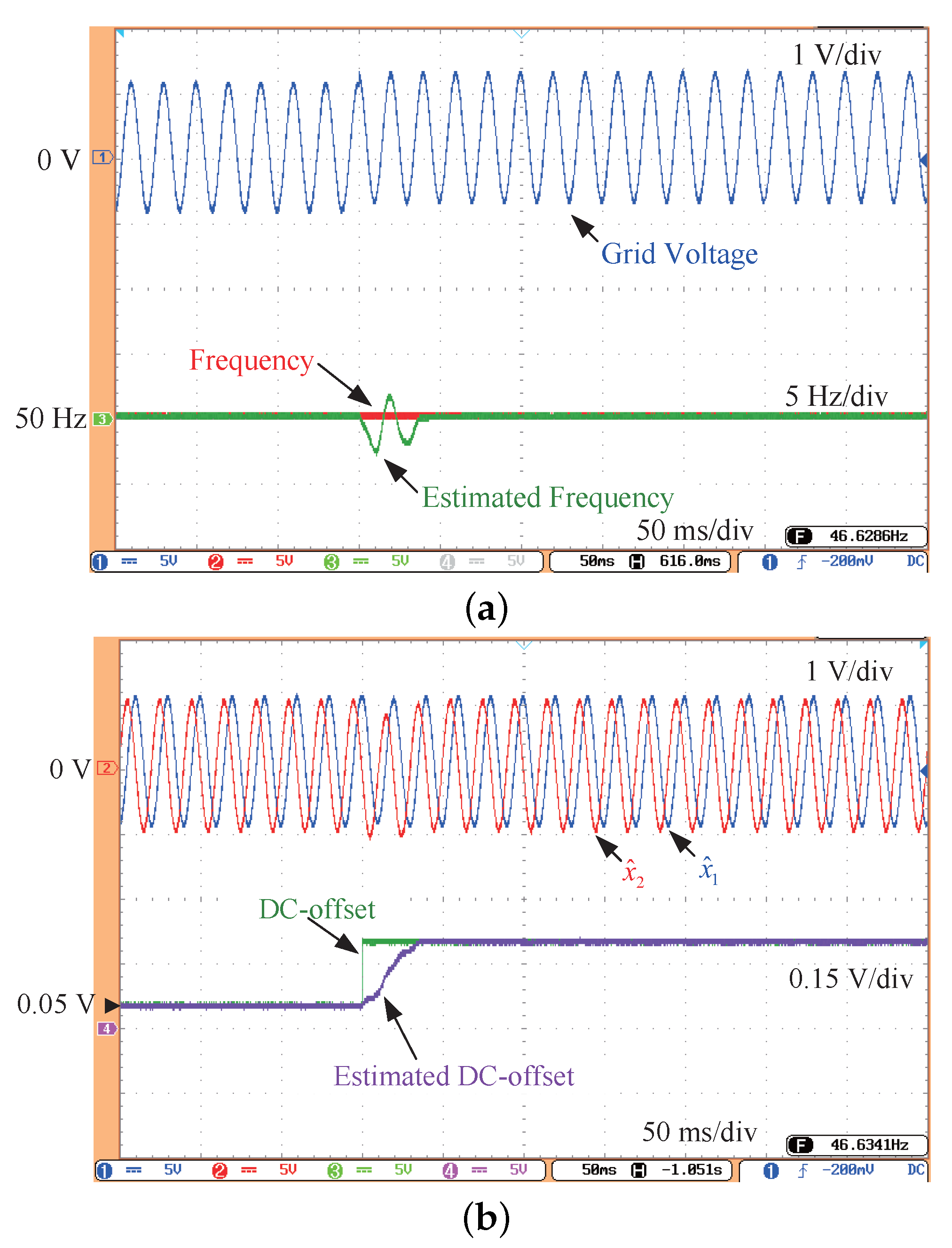
Case D: As shown in Figure 5a, the grid voltage undergoes a DC offset jump from 0.05 p . u . to 0.2 p . u . The estimated frequency waveforms rapidly converge to the true value within 50 ms , with minimal deviation. Figure 5b illustrates the waveforms for the DC offset, estimated sinusoidal component x ^ 1 , orthogonal sinusoidal component x ^ 2 , and estimated DC offset x ^ 3 . The estimated DC offset waveform converges to the true value within 50 ms , without significant overshoot. Case D further confirms the dynamic and steady-state performance of the proposed method under conditions of varying DC offset.
Figure 5. Experimental result under Case D. (a) The grid voltage, frequency, and estimated frequency. (b) x ^ 1 , x ^ 2 , DC-offset and estimated DC offset.
Case E: As shown in Figure 6a, the grid voltage contains a 0.05 p . u . DC offset and undergoes high-order harmonic injection. Figure 6b displays the waveforms for the DC offset, estimated sinusoidal component x ^ 1 , orthogonal sinusoidal component x ^ 2 , and estimated DC offset x ^ 3 . Despite the presence of high-order harmonic injection, the estimated values exhibit only minor oscillations. Case E further demonstrates the robustness of the proposed method in the presence of high-order harmonic disturbances.
Figure 6. Experimental result under Case E. (a) The grid voltage, frequency, and estimated frequency. (b) x ^ 1 , x ^ 2 , DC-offset and estimated DC offset.
Across five representative tests the proposed method consistently converged in under 50 ms, eliminated steady-state error in the presence of DC offset, and showed only minor residual error under harmonic injection. These results confirm its fast dynamics and robustness for practical grid-voltage parameter estimation.

4. Conclusions

This paper presents a novel adaptive observer for estimating grid voltage parameters in a single-phase system, especially in the presence of DC offset. The stability of the proposed method is rigorously demonstrated using Lyapunov’s stability theorem, guaranteeing stability provided that k 2 Γ k 1 > 0 . Compared with traditional methods, the proposed observer exhibits fast dynamics (within 50 ms) and zero steady-state error under frequency variations and DC offset. In addition, the amplitude of the DC offset can be estimated. Experimental results show that, even under high-order harmonic injection, the estimation errors remain small. This property facilitates the practical implementation of the proposed method.

Author Contributions

Conceptualization, J.X. and X.W.; methodology, J.X. and Z.D.; software, J.Z. and S.T.; validation, J.X., J.Z. and S.T.; formal analysis, S.T.; investigation, J.X., Z.D. and X.W.; writing—original draft preparation, J.X.; writing—review and editing, J.X.; visualization, X.W.; supervision, X.W.; project administration, Z.D. All authors have read and agreed to the published version of the manuscript.

Funding

This research received no external funding.

Data Availability Statement

The original contributions made in this study are contained within the article. Any further questions can be addressed to the corresponding author.

Acknowledgments

This paper is based on the project “Research on Key Performance and Evaluation Technology of Domestic Gateway Electricity Meters under Complex Working Conditions” (Project No. 2024 Yudian Technology 34#).

Conflicts of Interest

Authors Ji Xiao, Jiaming Zhang and Shishun Tan were employed by the Marketing Service Center of State Grid Chongqing Electric Power Company. The remaining authors declare that the research was conducted in the absence of any commercial or financial relationships that could be construed as a potential conflicts of interest.

Abbreviations

The following abbreviations are used in this manuscript:
DCDirect current
ACAlternating current
GCDGGrid-connected distributed generation
FFTFast Fourier Transform
DFTDiscrete Fourier Transform
OSGOrthogonal Signal Generator
PLLphase locked loop
SOGIsecond-order generalized integrator
CCF-PLLcomplex-coefficient filter PLL
DOEC-PLLDC offset error compensation PLL
VTD-PLLvariable time-delay PLL

References

  1. Pahlevani, M.; Eren, S.; Guerrero, J.M.; Jain, P. A Hybrid Estimator for Active/Reactive Power Control of Single-Phase Distributed Generation Systems with Energy Storage. IEEE Trans. Power Electron. 2016, 31, 2919–2936. [Google Scholar] [CrossRef]
  2. Strasser, T.; Andren, F.; Kathan, J.; Cecati, C.; Buccella, C.; Siano, P.; Leitão, P.; Zhabelova, G.; Vyatkin, V.; Mařík, V.; et al. A Review of Architectures and Concepts for Intelligence in Future Electric Energy Systems. IEEE Trans. Ind. Electron. 2015, 62, 2424–2438. [Google Scholar] [CrossRef]
  3. Jia, K.; Yang, Z.; Fang, Y.; Bi, T.; Sumner, M. Influence of Inverter-Interfaced Renewable Energy Generators on Directional Relay and an Improved Scheme. IEEE Trans. Power Electron. 2019, 34, 11843–11855. [Google Scholar] [CrossRef]
  4. Prakash, S.; Singh, J.K.; Behera, R.K.; Mondal, A. A Type-3 Modified SOGI-PLL with Grid Disturbance Rejection Capability for Single-Phase Grid-Tied Converters. IEEE Trans. Ind. Appl. 2021, 57, 4242–4252. [Google Scholar] [CrossRef]
  5. Trinh, Q.N.; Wang, P.; Tang, Y.; Koh, L.H.; Choo, F.H. Compensation of DC Offset and Scaling Errors in Voltage and Current Measurements of Three-Phase AC/DC Converters. IEEE Trans. Power Electron. 2018, 33, 5401–5414. [Google Scholar] [CrossRef]
  6. Tian, Y.; Zhang, C. An Improved Accuracy Harmonic Extraction Method for Microcontrollers. IEEE Trans. Ind. Electron. 2025, 72, 5344–5352. [Google Scholar] [CrossRef]
  7. Liu, H.; Hu, H.; Chen, H.; Zhang, L.; Xing, Y. Fast and Flexible Selective Harmonic Extraction Methods Based on the Generalized Discrete Fourier Transform. IEEE Trans. Power Electron. 2018, 33, 3484–3496. [Google Scholar] [CrossRef]
  8. Borkowski, J.; Kania, D.; Mroczka, J. Interpolated-DFT-Based Fast and Accurate Frequency Estimation for the Control of Power. IEEE Trans. Ind. Electron. 2014, 61, 7026–7034. [Google Scholar] [CrossRef]
  9. Kuwałek, P.; Bracale, A.; Sikorski, T.; Rezmer, J. Synchronized Approach Based on Empirical Fourier Decomposition for Accurate Assessment of Harmonics and Specific Supraharmonics. IEEE Trans. Ind. Electron. 2025, 72, 992–1002. [Google Scholar] [CrossRef]
  10. Derviškadić, A.; Romano, P.; Paolone, M. Iterative-Interpolated DFT for Synchrophasor Estimation: A Single Algorithm for P- and M-Class Compliant PMUs. IEEE Trans. Instrum. Meas. 2018, 67, 547–558. [Google Scholar] [CrossRef]
  11. Song, J.; Mingotti, A.; Zhang, J.; Peretto, L.; Wen, H. Fast Iterative-Interpolated DFT Phasor Estimator Considering Out-of-Band Interference. IEEE Trans. Instrum. Meas. 2022, 71, 9005814. [Google Scholar] [CrossRef]
  12. Li, M.; Nian, H.; Li, H.; Hu, B.; Liao, Y.; Li, H.; Liu, Y.; Wang, Y. HW-DFT-Based Measurement Method of Frequency-Coupling Characteristics Considering Fundamental Frequency Deviation for Stability Analysis. IEEE Trans. Power Electron. 2023, 38, 6613–6626. [Google Scholar] [CrossRef]
  13. Lin, H.C. Power Harmonics and Interharmonics Measurement Using Recursive Group-Harmonic Power Minimizing Algorithm. IEEE Trans. Ind. Electron. 2012, 59, 1184–1193. [Google Scholar] [CrossRef]
  14. Zhang, Z.; Guo, M.; Lu, Y.; Hu, X.; Xu, X.; Wu, C.; Ma, R.; Yang, Y. An Adaptive Enhanced Complex-Coefficient Filter-Based PLL in Variable Frequency Grid. IEEE Trans. Power Electron. 2024, 39, 3950–3955. [Google Scholar] [CrossRef]
  15. Dai, Z.; Li, G.; Fan, M.; Huang, J.; Yang, Y.; Hang, W. Global Stability Analysis for Synchronous Reference Frame Phase-Locked Loops. IEEE Trans. Ind. Electron. 2022, 69, 10182–10191. [Google Scholar] [CrossRef]
  16. Han, Y.; Luo, M.; Zhao, X.; Guerrero, J.M.; Xu, L. Comparative Performance Evaluation of Orthogonal-Signal-Generators-Based Single-Phase PLL Algorithms—A Survey. IEEE Trans. Power Electron. 2016, 31, 3932–3944. [Google Scholar] [CrossRef]
  17. Xiao, F.; Dong, L.; Li, L.; Liao, X. A Frequency-Fixed SOGI-Based PLL for Single-Phase Grid-Connected Converters. IEEE Trans. Power Electron. 2017, 32, 1713–1719. [Google Scholar] [CrossRef]
  18. Golestan, S.; Monfared, M.; Freijedo, F.D. Design-Oriented Study of Advanced Synchronous Reference Frame Phase-Locked Loops. IEEE Trans. Power Electron. 2013, 28, 765–778. [Google Scholar] [CrossRef]
  19. Hwang, S.-H.; Liu, L.; Li, H.; Kim, J.-M. DC Offset Error Compensation for Synchronous Reference Frame PLL in Single-Phase Grid-Connected Converters. IEEE Trans. Power Electron. 2012, 27, 3467–3471. [Google Scholar] [CrossRef]
  20. Ozdemir, A.; Yazici, I. Fast and robust software-based digital phase locked loop for power electronics applications. IET Gener. Transmiss. Distrib. 2013, 7, 1435–1441. [Google Scholar] [CrossRef]
Disclaimer/Publisher’s Note: The statements, opinions and data contained in all publications are solely those of the individual author(s) and contributor(s) and not of MDPI and/or the editor(s). MDPI and/or the editor(s) disclaim responsibility for any injury to people or property resulting from any ideas, methods, instructions or products referred to in the content.

Article Metrics

Citations

Article Access Statistics

Multiple requests from the same IP address are counted as one view.