Abstract
Backscatter technologies promise to enable large-scale, battery-free sensor networks by modulating and reflecting ambient radio frequency (RF) carriers rather than generating new signals. Translating this potential into practical deployments—such as distributed photovoltaic (PV) power systems—necessitates realistic modeling that accounts for deployment variabilities commonly neglected in idealized analyses, including uncertain hardware insertion loss, non-ideal antenna gain, spatially varying path loss exponents, and fluctuating noise floors. In this work, we develop a practical model for reliable backscatter communications that explicitly incorporates these impairing factors, and we complement the theoretical development with empirical characterization of each contributing term. To validate the model, we implement a frequency-shift keying (FSK)-based backscatter system employing a non-coherent demodulation scheme with adaptive bit-rate matching, and we conduct comprehensive experiments to evaluate communication range and sensitivity to system parameters. Experimental results demonstrate strong agreement with theoretical predictions: the prototype tag consumes 825 µW in measured operation, and an integrated circuit (IC) implementation reduces consumption to 97.8 µW, while measured communication performance corroborates the model’s accuracy under realistic deployment conditions.
1. Introduction
The past few years have seen the rapid development of the Internet of Things (IoT) and an increasing focus on smart cities, Industry 4.0, and sustainable development [1,2]. To meet the demand for efficiency and low cost, emerging backscatter communication technologies utilize existing ambient wireless carriers to convey information [3,4] instead of generating them, which is promising to open up opportunities of battery-free wireless communications. Thus, various sensing applications in the wild can be realized with further lower deployment and maintenance cost. In particular, battery-free sensing becomes especially valuable in harsh environments or geographically dispersed infrastructures where traditional power supply and frequent maintenance are difficult or costly.
To name a few, in mountainous areas where centralized photovoltaic (PV) power generation systems cannot be deployed [5], distributed PV power generation systems have attracted much attention due to their flexibility of deployment, reliability of power supply, and ease of operation and maintenance [6,7]. However, these distributed systems are often deployed in remote or harsh environments, where the sensing nodes must operate reliably over long periods without direct human intervention. This imposes stringent requirements on the energy efficiency, cost-effectiveness, and communication reliability of the underlying wireless technologies. Backscatter communication technology, with its ultra-low power consumption and infrastructure reuse, offers a promising solution to meet the real-time monitoring needs of such distributed PV systems while significantly reducing both deployment and maintenance costs.
Nevertheless, existing backscatter communication models generally assume idealized conditions and fail to account for practical deployment factors such as hardware insertion loss, antenna gain imperfections, environmental path loss exponent variation, and noise floor fluctuations, all of which significantly degrade system performance in real scenarios. Specifically, the non-ideal characteristics of the hardware can lead to severe insertion loss and thus affect the system’s performance, which is typically overlooked in simplified models. Furthermore, antennas may suffer from occlusion, improper mounting angles, or poor workmanship, causing imperfect gain and deviations in the actual performance from the model predictions. Meanwhile, the path loss exponent differs from that in free space and is influenced by environmental interference, resulting in mismatches between actual measurement results and models. And the noise floor level affects the demodulation threshold, consequently impacting the performance of demodulation. These practical challenges highlight the necessity to develop an accurate backscatter communication model that explicitly incorporates such deployment realities, enabling more reliable system design and performance prediction for distributed PV power generation environments.
In this paper, we propose a backscatter communication model based on frequency-shift keying (FSK) that incorporates critical factors involved in practical deployment, thereby enhancing the model’s reliability. Moreover, we built an FSK-based backscatter communication system to validate our model, aiming to provide a comprehensive assessment of the system’s performance under real-world deployment scenarios. We also designed a non-coherent demodulation scheme with an adaptive bit-rate matching filter to improve the system performance. Finally, we conducted a series of experiments to validate the proposed model and evaluated the performance of the FSK-based backscatter system. The results indicate that the measured maximum distance of 14 m closely aligns with the theoretical prediction, validating the model’s correctness under real-world deployment scenarios.
Based on the above description, our contributions can be summarized as follows:
- •
- We propose a novel FSK-based backscatter communication model that explicitly incorporates practical deployment factors such as hardware insertion loss, imperfect antenna gain, environmental path loss exponent variation, and noise floor fluctuations, which are often simplified or not fully considered in the idealized analyses of existing models.
- •
- We built an FSK-based backscatter communication system using a non-coherent demodulation scheme with an adaptive bit-rate matching filter.
- •
- We conducted comprehensive performance evaluations and experimental validations in realistic deployment scenarios.
The remainder of this paper is organized as follows. Section 2 describes some related works. Section 3 introduces the link budget. Section 4 details the design of the FSK-based backscatter communication system. Then, Section 6 discusses the numerical and experimental validation of the proposed backscatter communication system. Finally, Section 8 concludes this paper.
To clarify the symbols used throughout this paper, key notations are summarized as follows:
- •
- Backscatter system parameters: denotes the transmitter output power (unit: dBm); , , and represent the antenna gains of the transmitter, backscatter tag, and receiver, respectively (unit: dBi); is the tag insertion loss (unit: dB); d stands for the propagation distance between the tag and the transmitter/receiver (unit: m); and are the channel attenuation exponents for the forward (transmitter-to-tag) and backward (tag-to-receiver) channels, respectively.
- •
- Signal and noise parameters: is the carrier wavelength (unit: m); and are the input and output signal powers of the tag (unit: dBm); is the received signal power at the receiver (unit: dBm); represents the ambient noise floor (unit: dBm); S is the minimum signal-to-noise ratio (SNR) threshold for successful demodulation (unit: dB); is the energy per bit (unit: J/bit); is the two-sided noise power spectral density (unit: W/Hz); denotes the receiver noise bandwidth (unit: Hz).
- •
- Modulation and demodulation parameters: is the carrier frequency (unit: Hz); and are the frequency shift introduced by the tag and the system frequency offset, respectively (unit: Hz); B is the system operating bandwidth (unit: Hz); and are the low and high carrier frequencies for FSK modulation (unit: Hz); is the signal bit rate (unit: bps); T is the bit duration (unit: s); represents the bit error rate (BER).
2. Related Work
There has been a lot of excellent work on backscatter. The authors of [8] developed and validated GPSMirror, an ultra-low-power system that extends GPS positioning to shadowed and indoor regions using a highly sensitive backscatter device, which re-radiates weak GPS signals and can be adapted for broader applications. In addition to the above, ref. [9] proposes SecureTag, a system designed to add defense in depth against active attacks by integrating physical layer information with upper-layer protocols. The principles of backscatter have also been successfully applied to other domains, such as enhancing existing protocols like LoRa [10]. Other works have focused on new backscatter system architectures and radio frequency (RF) computing hardware [11,12]. Recent studies have further extended the application scope of backscatter by demonstrating impressive long-range performance and compatibility with commodity systems such as Wi-Fi and LiFi [13,14]. In parallel, other research explores ultra-low-power communication by repurposing ambient signals, including cellular-generated carriers, which shares conceptual similarities with ambient backscatter communication [15]. Backscatter communications apply to several IoT verticals including smart city and environmental sensing, structural health monitoring, logistics and asset tracking, precision agriculture, wearable/medical sensing, and industrial automation. Practical batteryless operation enabled by energy harvesting is critical for many of these applications [16] and complements efforts to reduce tag insertion loss and extend device lifetime. At the network level, decision fusion and collaborative inference are important when combining many weak backscatter links [17]. These verticals impose strict constraints on energy, range, dense-deployment handling, interference, and security, motivating further work on energy harvester and tag antenna co-design, collision–mitigation, and coordination strategies for dense fleets, multi-tag fusion algorithms, and system-level integration with PV monitoring platforms.
Previous research has also explored modeling backscatter in metal and concrete environments, sometimes for applications like structural health monitoring [18,19]. In contrast, our model emphasizes broader scenarios in practical deployments, explicitly considering many variable factors often overlooked in idealized models that are crucial for system reliability. By comprehensively integrating these practical deployment factors, our model provides a more robust and accurate framework for backscatter communication, especially vital for complex deployment environments like distributed photovoltaic power generation systems, which demand long-term reliable operation.
Backscatter communication based on FSK modulation was extensively studied in [20,21] and is applicable to distributed PV power generation systems due to its demonstrated capacity to significantly enhance communication range compared to traditional on–off keying (OOK) modulation. In addition, this approach separates the direct and scattered channels [22], preventing the backscatter signal from being interfered with by signals from other bands. We chose FSK-based backscatter for precise modeling because of its high immunity to interference and its long communication range. However, despite the numerous advantages FSK modulation offers at the physical layer, ensuring reliable signal demodulation remains challenging in practical deployments, especially in complex environments like distributed PV systems, which may involve tags from various manufacturers or with different configurations. Existing FSK demodulation studies [20,21] and non-coherent detection methods [23] typically assume that the tag’s bit rate is known or fixed, whereas in real-world scenarios, the tag’s bit rate may be unknown or dynamically changing [24]. Such bit rate mismatch can lead to a significant degradation in the performance of conventional demodulation schemes. Addressing this critical issue by enabling reliable, adaptive demodulation for tags with unknown bit rates is precisely the core focus of our non-coherent demodulation design and the adaptive bit rate matching scheme in Section 4 of this paper. To better position our contribution, we include Table 1, which summarizes and categorizes the reviewed works along the main distinguishing axes.

Table 1.
Comparison of representative backscatter works along key distinguishing axes.
It is important to explicitly distinguish our work from Qian et al.’s study [23], which also explores non-coherent detection for ambient backscatter systems. The research primarily concentrates on theoretical analysis of non-coherent detection principles and derives the BER performance under idealized assumptions. It particularly assumes that the tag’s bit rate is known and fixed, which is a critical simplification that deviates from real-world scenarios. In contrast, our research addresses the practical limitation of unknown or dynamically varying tag bit rates by integrating an adaptive bit-rate matching scheme into the non-coherent demodulation design. Furthermore, the theoretical framework does not incorporate practical deployment factors, and its algorithms are not validated through physical experiments. Our work, however, embeds the non-coherent demodulation scheme into a comprehensive model that accounts for these real-world impairments and verifies the design through a physical prototype and outdoor experiments, bridging the gap between theoretical analysis and practical application.
3. Link Budget
Unlike conventional wireless communication models that assume a single reciprocal link between transmitter and receiver, backscatter communication involves two separate propagation paths: a forward channel from the transmitter to the tag and a backward channel from the tag to the receiver. As a result, an accurate link budget must incorporate hardware-dependent parameters such as tag insertion loss and antenna gains, which directly affect end-to-end signal strength. The architecture of the FSK-based backscatter system is shown in Figure 1. The system comprises three primary components: a transmitter tasked with generating the excitation signal, a single-antenna tag utilizing an RF switch for signal modulation, and a receiver dedicated to signal demodulation.
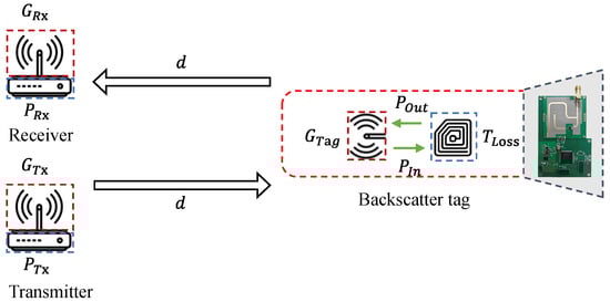
Figure 1.
FSK-based backscatter model.
The backscatter communication process can be characterized by two sequential propagation stages. In the first stage, the transmitter radiates an excitation signal from an omnidirectional antenna, and this signal undergoes propagation loss before reaching the tag. The tag intercepts the incident signal with its own omnidirectional antenna; then, the received signal is reflected from the antenna port after modulation by the tag’s internal circuitry. Denoting the propagation distance for this stage as d, the associated attenuation can be expressed by the electromagnetic propagation loss relation as follows:
where is the wavelength of the carrier wave, and is the channel attenuation index for the first phase, equal to 2 in free-space propagation. However, the actual channel attenuation index is generally greater than 2 due to the factors such as scattering by the air dust and ground reflection of electromagnetic waves in real-world environments. Assuming the transmitting power is , the transmitter antenna gain is , and the tag antenna incident gain is , the signal power arriving at the tag’s internal circuit can be expressed as
The second phase of propagation involves the signal being emitted from the tag’s antenna, traveling a distance of d through the wireless channel and being received by the receiver’s omnidirectional antenna. The power delivered to the receiver is consequently diminished by two separate contributions: the insertion loss , representing losses within the tag, and the channel propagation loss , which accounts for distance-dependent path loss and environmental attenuation on the path. Analogous to the first phase, can be modeled as
where is the channel attenuation index for the second phase. Assuming the output power from the tag is and considering that the tag employs a single antenna with a gain denoted as for both receiving and transmitting purposes, the power of the signal received by the receiver can be expressed as follows:
The insertion loss of the tag can be expressed as the difference between the received power and the emitted power of the tag: . Assuming that the distance between the first and the second phase of propagation is equal, the received signal at the receiver can be expressed as
In assuming that the noise floor is and the threshold SNR required for successful demodulation is S, stable communication can be maintained when . When , it signifies the theoretical critical communication distance for the tag. The distance-dependent terms contained in are and . Consequently, we can get
Thus, our theoretical maximum distance is expressed as
Within the link budget framework for the FSK-based backscatter system, the theoretical maximum communication distance can be extended by improving any factor that increases received power or reduces the required signal to the noise ratio. In practice, this entails increasing the excitation source transmit power, choosing antennas with higher realized gain and proper installation to maximize effective gain, lowering the ambient noise floor through site selection or receiver design improvements, reducing the propagation attenuation by deploying in less lossy environments or optimizing geometry, and minimizing tag insertion loss via improved circuit design and impedance matching. Each of these measures maps directly to terms in the above equation, and their combined optimization determines the achievable increase in .
4. Design
This section begins with a brief overview of the basic principles of backscatter communication, followed by a detailed explanation of our proposed design. Central to our design is the use of FSK modulation to encode information onto the backscatter signals, enabling reliable data transmission. Additionally, we employed a non-coherent demodulation scheme to remove the need for precise carrier recovery, thereby simplifying receiver implementation and improving robustness against phase noise and frequency drift. In addition, we integrated an adaptive bit-rate matching filter to identify and decode specific tags that operate at different bit rates.
We present the communication process of FSK-based backscatter in Figure 1. The transmitter equipped with single-antenna sends a single tone as excitation, where is the carrier frequency. The backscatter tag, operating within a bandwidth B, modulates the incident excitation signal by toggling an RF switch. To avoid interference along the direct path from the transmitter to the receiver, the frequency of the reflected signal is offset from the original excitation frequency. Therefore, the signal received at the receiver can be expressed as
where is the signal modulated by the tag, is the signal transmitted through the backward channel, denotes the frequency shift introduced, is the system frequency offset, and represents the additive Gaussian white noise. Subsequently, the receiver employs our demodulation scheme, which incorporates adaptive bit-rate matching functionality, to demodulate the incoming signal .
4.1. Modulation of FSK-Based Backscatter Communication
Rather than actively transmit its own wireless signals, the backscatter tags modulate the captured ambient wireless signal by altering the reflective properties of the circuitry. The key parameter in this process is the reflection coefficient, which is
where is the load impedance, and is the characteristic impedance of the backscatter tag.
In the FSK modulation scheme, the modulation of information is accomplished through the variation in the switching frequency of the RF switch. The resultant backscatter signals are positioned at frequencies and , respectively, where the operating bandwidth is defined as B, and the carrier frequency is . We denote and for the purpose of succinctness. Accordingly, the signal modulated by the tag can be represented as
where is a square wave with period T, representing the switching between bit “0” and bit “1”. So, the FSK-based backscatter signal is
Signal recovery is attained through our non-coherent demodulation design, the specifics of which are elaborated on in the next subsection.
4.2. Non-Coherent Demodulation
As discussed in Section 2, backscatter communication in practical deployments such as distributed photovoltaic systems faces complex and varying environments, as well as potential challenges from unknown tag bit rates. To address these issues, and to provide stronger robustness against phase noise and frequency drift, as well as more effective performance in low-SNR environments, we employed a non-coherent demodulation scheme. As shown in Figure 2, the demodulation module consists of the following main modules: a down-conversion module; finite impulse response (FIR) filter module; low-pass filter module; and decode module. Firstly, the signal is shifted from the RF band to the base band by the down-conversion module to eliminate the frequency shift , and then the signal is
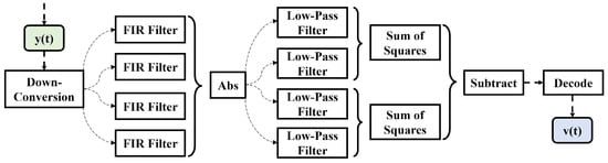
Figure 2.
Demodulation module.
Following the acquisition of the base band signal, its orthogonal components—the in-phase (I) and quadrature (Q) channels—are channeled in parallel through a pair of matched filters, which implicate a quadruple matched filter setup for the front end of an FSK communication channel. This structure is implemented in the FIR filter module, where the filter coefficients will help with the adaptive code rate matching functionality.
Then, the envelope detector signals at distinct frequencies are attained. Notably, the frequency offset is significantly smaller compared to the bit rate and noise is not taken into account for analytical convenience. The extraction of four distinct base band signals is expressed as
Then, each of the four signals passes through a low-pass filter after taking the absolute value. These filters are tuned to a cutoff frequency matching the base band frequency . Subsequently, the squared magnitudes are summed based on the following combinations: the FSK low-frequency component of the I-signal is summed with its counterpart, the FSK low-frequency component of the Q-signal ; similarly, the FSK high-frequency component of the I-signal is summed with the FSK low-frequency component of the Q-signal . Subtracting the resulting signals gives
The above process eliminates the system frequency offset , yielding a bipolar waveform , which is then directed to the decoding module for the extraction of the embedded information.
To quantify the performance of the non-coherent demodulation scheme, we will derive its theoretical BER expression under AWGN channel conditions. In FSK modulation, bits ‘0’ and ‘1’ are represented by two orthogonal carrier frequencies, and , respectively. Assuming each bit has a duration T and energy , the transmitted signal can be expressed as
for . The received signal includes the modulated backscatter signal superimposed with AWGN . Thus, the signal at the receiver front-end can be written as
where is AWGN with a zero mean and a two-sided power spectral density of . According to the non-coherent demodulation principle described in Section 4.2, the receiver processes the signal using two sets of matched filters (corresponding to and ) and envelope detectors. For FSK signals, if the two carrier frequencies and satisfy the orthogonality condition, then in an AWGN channel, the theoretical BER for non-coherent FSK demodulation can be expressed as
where is the theoretical BER, is the energy per bit, and is the noise power spectral density. To relate this to the SNR in our system, we know that for a receiver with noise bandwidth , the noise power can be expressed as . The received signal power is related to the energy per bit . If the average received power is and the bit rate is , then . Therefore, the BER expression can be rewritten in terms of the received SNR, defined as :
Substituting these into the BER formula, we get
In an ideal FSK system, it is often assumed that the noise bandwidth is approximately equal to the bit rate . In this case, the expression simplifies to
This theoretical curve sets a benchmark for our system’s performance. In Figure 3, we demonstrate through simulation our adaptive non-coherent scheme’s BER performance.
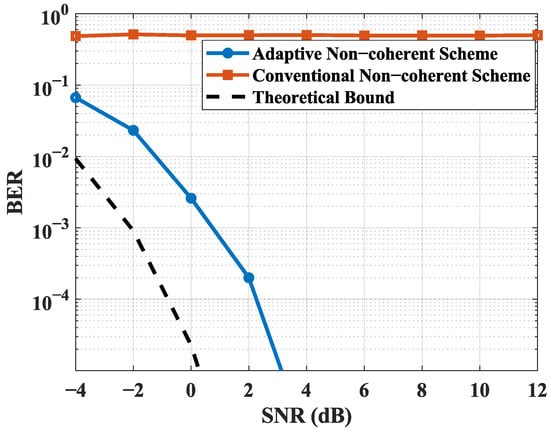
Figure 3.
BER performance comparison between the proposed adaptive non-coherent demodulation scheme and the conventional method under various bit-rate mismatch condition.
It is worth noting that [23] also explored non-coherent detection for ambient backscatter systems. Their work primarily focused on providing theoretical analysis and algorithm design for non-coherent detection, specifically deriving BER performance. While both works leverage non-coherent detection principles, our scheme offers distinct advantages and unique contributions for practical deployments. The paramount and unique contribution of our scheme lies in its adaptive bit-rate matching capability. This feature is crucial for tackling the practical challenge of unknown or varying tag bit rates—a common scenario in distributed PV systems. Therefore, our comprehensive system design, combining FSK modulation with adaptive bit-rate matching, delivers unparalleled robustness and adaptability for real-world backscatter deployments, representing a significant differentiation compared to existing approaches.
4.3. Adaptive Bit-Rate Matching
As emphasized in Section 2, in complex deployment environments such as distributed photovoltaic systems, backscatter tags may operate at various bit rates, and the receiver often lacks prior knowledge of the specific configuration of the target tag [24]. To address this critical challenge and fully leverage the inherent advantages of non-coherent demodulation in handling weak signals and environmental interference, we propose an adaptive bit-rate matching scheme. This scheme aims to achieve accurate filtering and reliable data recovery for specific tags without requiring prior knowledge of the tag’s bit rate. With the premise that the preamble sequence of the tag is known, we concurrently vary the duration of the FIR filter’s coefficient sequence , represented as N, and the sampling rate of the decoding module. During the correlation operation executed by the decode module, the sampling rate corresponding to the maximum correlation peak magnitude is extracted. This optimally identified sampling frequency directly corresponds to the bit rate of the target tag.
As shown in Figure 4, the height of the correlation peak varies at different bit rates, and the correlation peak is highest when the bit rate is 2 kHz, thus determining the bit rate for the specific tag and decoding it accordingly. To further evaluate the performance of our proposed adaptive non-coherent demodulation scheme, we consider a realistic deployment scenario where the bit rate of the target backscatter tag is unknown a priori. Although different tags in the environment may operate at varying bit rates, the receiver aims to decode a single-target tag without prior knowledge of its configuration. In this context, a conventional non-coherent demodulator typically assumes a fixed bit rate, which can lead to symbol misalignment and significant performance degradation if the assumed rate does not match the actual tag rate.
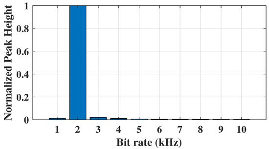
Figure 4.
Normalized peak heights at different bit rates.
Figure 3 illustrates the BER performance of the proposed scheme compared to a conventional non-coherent method under bit-rate mismatch condition. As shown, our adaptive demodulation algorithm accurately estimates the correct bit rate of the target tag and achieves BER performance close to the ideal case where the bit rate is known a priori. In contrast, the conventional method exhibits a high BER under bit-rate mismatch conditions. This result validates the robustness and practical effectiveness of our approach in multi-rate environments.
To further clarify, the non-coherent detection scheme in Qian et al.’s study [23] lacks adaptability to tag bit rates, as it assumes prior knowledge of the tag’s configuration. This is a constraint that limits its utility in distributed PV systems, where tags may have varying bit rates without pre-shared parameters. Our adaptive bit-rate matching scheme, by contrast, dynamically adjusts the FIR filter coefficient duration and decoding sampling rate, identifying the optimal bit rate via correlation peak analysis, as shown in Figure 4. This capability ensures reliable demodulation even when the tag’s bit rate is unknown.
5. Implementation
Backscatter tag: Our backscatter tag prototype was realized on a printed circuit board (PCB) and assembled using standard commercial off-the-shelf (COTS) components. The tag integrates an ADG902 RF switch for signal modulation. Furthermore, the tag is equipped with an IGLOO Nano AGLN250 field-programmable gate array (FPGA), which is responsible for coordinating the RF switch’s operations. The measured dynamic power is 825 µW, and the static power is 36.3 µW. We also conducted an integrated circuit (IC) design, and the total dynamic power consumption is 97.8 µW.
Transmitter and receiver: We employed a dedicated signal generator to generate the excitation signal at a frequency of 474.5 MHz with a power level of 20 dBm. For reception, we implemented a Universal Software Radio Peripheral (USRP) X310 as the receiver, with signal processing tasks handled by a DELL G16 laptop. In order to prevent interference from the direct channel, a frequency shift of MHz is applied. Consequently, the backscatter signal is received at a frequency of 499.5 MHz.
Experimental setup: To evaluate the performance of the FSK-based backscatter system, we conducted experiments in an outdoor rooftop environment. As shown in Figure 5, we placed the receiver and the transmitter in adjacent positions. To facilitate the calculation of the absolute distance, the tag was placed on the perpendicular bisector of the line connecting the receiver and the transmitter, with equal distances from the tag to the receiver and from the tag to the transmitter.
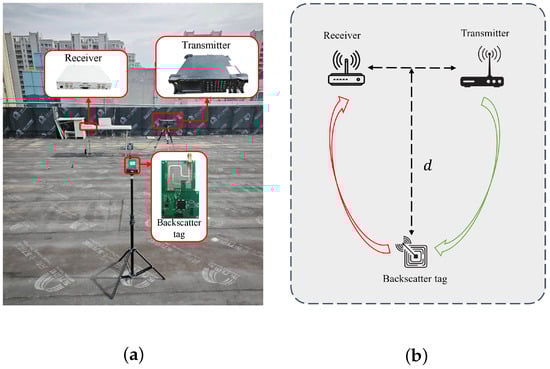
Figure 5.
(a) Experimental setup on the rooftop; (b) experimental setup schematic, where the red and green arrows indicate the signal transmission paths.
6. Evaluation
Communication Distance: In this study, we conducted experiments to test the system in real-world scenarios in terms of BER versus distance and maximum communication distance. As shown in Figure 6, our experimental results show that the BER is essentially 0 within 14 m, but suddenly rises after 14 m. It can be assumed that 14 m is the maximum distance of our system. Notably, within the communication range of 0–15 m, subtle periodic fluctuations in BER are observed, with an amplitude of less than 0.001. This phenomenon can be primarily ascribed to two key contributing factors:
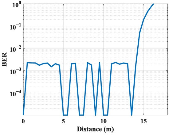
Figure 6.
BER variation with distance.
- Multipath fading in the outdoor rooftop environment: The experimental deployment on the rooftop introduces a propagation scenario replete with reflective surfaces, including metallic heating, ventilation, and air conditioning infrastructure and concrete parapets. These surfaces induce multipath propagation, wherein the backscatter signal reaches the receiver via two primary components: the line-of-sight (LoS) path and non-line-of-sight (NLoS) reflected paths. The superposition of these components gives rise to constructive or destructive interference, manifesting as periodic fluctuations in the received signal power with an approximate period of 1–2 m. Through translation to the BER domain, such interference induces minor yet measurable BER variations. This phenomenon aligns with fundamental electromagnetic propagation principles. The carrier frequency employed is 474.5 MHz, which corresponds to a wavelength () of approximately 0.63 m and yields an interference period of , around 0.31 m. Owing to the 1 m distance step size adopted in the experimental design, this fine-grained interference period remains unresolved, resulting in the observed low-amplitude BER fluctuations.
- Dynamic environmental interference in the outdoor setting: The rooftop experimental environment is subject to real-time dynamic disturbances that perturb signal propagation. First, temporary obstructions moved intermittently within the experimental area. Examples include staff passing through the rooftop with maintenance tools and cleaning equipment operating near the setup. These moving objects cause partial blocking or scattering of the backscatter signal, leading to transient dips in received power that further translate to subtle BER variations. Second, temporary electronic devices operate around the rooftop. Common examples are construction Walkie Talkies and deployed monitoring equipment. These devices emit electromagnetic radiation that overlaps with the experiment’s 474.5 MHz carrier frequency. This overlap introduces additional noise into the received signal and slightly reduces the SNR, which in turn contributes to BER fluctuations. Both the obstruction-induced power dips and device-generated noise collectively contribute to the low-amplitude BER fluctuations observed, and their combined interference effects align with the measured amplitude range of less than 0.001 for the BER variations.
Importantly, these observed fluctuations are negligible in magnitude and do not compromise the system’s reliability for distributed PV applications. The amplitude of the aforementioned fluctuations remains well within this acceptable threshold. Regarding the communication range, the sharp increment in BER beyond 14 m can be attributed to the received signal power dropping below the demodulation SNR threshold. This threshold was previously determined as 7 dB in Section 7. This finding confirms that 14 m represents the actual maximum communication distance of the proposed system.
Impact of Block: In real-world deployment scenarios, tags may encounter varying degrees of obstruction, such as frequent pedestrian traffic or the presence of obstacles between the tag and the receiver. To validate the system’s performance under obstructed conditions, we introduce controlled obstructions to assess whether the system’s BER significantly deteriorates when subjected to these impediments. As illustrated in Figure 7a, we maintained a fixed absolute distance of 14 m between the tag and both the transmitter and receiver. To simulate obstruction, a person was positioned in the propagation path to create the desired interference scenario. The result indicates that obstruction has a substantial impact on communication performance.
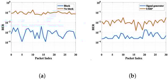
Figure 7.
(a) BER under conditions with and without a block; (b) BER under the conditions of a USRP or signal source as the excitation source.
Impact of Source: When the system is deployed, the excitation source may be changed, and we need to verify that the system can still work stably under different excitation sources. We used another USRP X310 (manufactured by Ettus Research, a National Instruments brand, Austin, TX, USA) as the excitation source, setting the frequency to 474.5 MHz and setting the power level to 20 dBm, and the tag was placed 14 m away from the receiver for testing and comparing the BER results obtained with the signal generator. The experimental results show that there is a slight increase in BER when USRP X310 is used as the excitation source. Therefore, different excitation sources will lead to variations in system performance.
Impact of Transmitter–Receiver Distance: The distance between the excitation source and the receiver influences the power level at which the excitation signal arrives at the receiver, which in turn affects the performance of the receiver’s low-noise amplifier (LNA). Consequently, it is imperative to ascertain the impact of varying this distance on overall system performance to inform appropriate adjustments in deployment strategies, ensuring optimal positioning for reliable communication. The tag was placed at the maximum distance of 14 m away from the receiver for testing, as depicted in Figure 8a; the system’s BER decreased gradually as the distance between the excitation source and the receiver increased, stabilizing after reaching a distance of 4 m with no further changes observed. Additionally, we introduced a metal barrier between the excitation source and the receiver as a physical isolation measure, and the resultant test outcomes, as shown in Figure 8b, confirm that such physical barriers can effectively mitigate interference to a considerable extent.
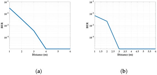
Figure 8.
(a) BER variation with the distance between receiver and transmitter; (b) BER with a metal barrier between the receiver and transmitter.
7. Model Validation
To obtain the power decay trend with respect to distance, we configure the attenuation coefficients of both propagation phases as parameters to be fitting. Leveraging test data, we employed the method of least squares fitting. Given the ambiguity surrounding the precise antenna gain values, we adopted a dual approach: firstly, we fixed the antenna gain at a nominal value of 3 dB for the fitting process; secondly, we treated the antenna gain as an additional parameter to be concurrently fitting alongside the attenuation factors, thereby exploring the optimal fit under varying assumptions.
The fitting curve for the first phase’s attenuation coefficient is illustrated in Figure 9a, with the attenuation coefficient estimated through least squares fitting being 2.56. The inferred transmitted power dBm is lower than the actual configured signal transmission power of 26 dBm (considering the transmitting antenna and the receiving antenna gain as a standard gain of 3 dBi). Similarly, Figure 9b shows the second phase of the fitting curve, and . The inferred transmitted power of dBm is lower than the actual configured signal transmission power of −56.2 dBm. The tag insertion loss can be extrapolated from the above results. Since the antenna gain is non-standard gain and is involved in the fitting as an overall parameter, it is easy to obtain dB. Through estimating dB and dB from the test results, dB.
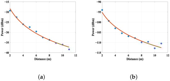
Figure 9.
(a) The fitting curve for the first phase; (b) the fitting curve for the second phase.
To characterize the ambient noise floor of the test environment, measurements were conducted during three separate time periods using two distinct spectrum analyzers: a portable TinySA unit (manufactured by Shenzhen XSH Smart Technology Co., Ltd., Shenzhen, Guangdong, China) and a more advanced RIGOL-RSA5065 analyzer (manufactured by RIGOL Technologies, Inc., Beijing, China). These measurements were performed in conjunction with various receiving antennas. Our findings reveal an average noise floor on the rooftop hovering around −124 dBm when measured over a bandwidth of 2 kHz. Then, we conducted a simulation study to analyze the demodulation threshold of our algorithm. By simulating the relationship between the system’s SNR and BER, we derived the following results. As illustrated in Figure 10, the system’s BER decreases to the orders of magnitude of at an SNR greater than 7 dB. Since it can be considered to have essentially no effect on communications at orders of magnitude of , we posit that the theoretical demodulation SNR threshold for our system is practically at 7 dB. Consequently, when the antenna gain is standard, the total link attenuation formula can be delineated as follows:
when dBm, and the calculated maximum theoretical communication distance is 13.6 m, which aligns well with the practically measured maximum communication distance of 14 m. In addition, if the hardware design is optimized to reduce insertion loss by 18 dB, which means that , the model predicts that the maximum range could be extended to 33 m.
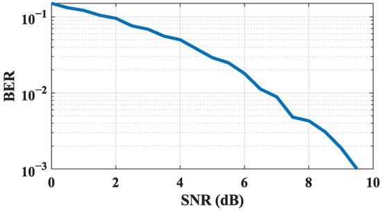
Figure 10.
Demodulation BER versus SNR.
8. Conclusions
In this paper, we present a model of an FSK-based backscatter system, encompassing not only the modeling of the link budget but also experimental validation. Furthermore, we built an FSK-based backscatter system and designed a non-coherent demodulation scheme with adaptive bit-rate matching for deployments in practical scenarios. This work holds significant implications for the practical application of backscatter technology, particularly in the context of distributed photovoltaic power generation systems, where it can serve as a low-power, dependable communication scheme. The meticulous link budget modeling facilitates the optimized deployment of tags. Our experimental findings align closely with theoretical predictions, thereby affirming the validity and utility of our model and designs.
For future research, we endeavor to explore several avenues to further advance the work presented herein. First, we will further reduce tag insertion loss through improved circuit design and deeper IC integration to extend communication range and lower power consumption. Second, we intend to perform extensive, long-term field trials in diverse distributed PV deployments to assess the impact of obstructions, complex terrain, and multi-tag coexistence on system reliability. Third, we will enhance the adaptive non-coherent demodulation and multi-rate identification and study link- and protocol-level solutions for multi-access and collision resilience. Fourth, we will extend the current link model to time-varying or fading channels and 3D antenna effects and investigate joint optimization with energy-harvesting and power management schemes. Finally, we will explore system security and coexistence strategies with legacy wireless systems. These directions aim to advance the current theoretical and prototype work toward robust, large-scale, and long-term practical deployments.
Author Contributions
Conceptualization, X.L.; methodology, X.L. and W.D.; validation, X.H. and B.Y.; resources, D.C. and W.W.; writing—original draft preparation, W.T., K.L. and Z.C.; writing—review and editing, D.C. and W.W.; project administration, W.W. All authors have read and agreed to the published version of the manuscript.
Funding
This research was funded by the Science and Technology Project of Guizhou Power Grid Co., Ltd., under Grant No. 060000KC24100003.
Data Availability Statement
The data presented in this study are available in the article.
Conflicts of Interest
Authors Xu Liu, Wu Dong, Xiaomeng He, Wei Tang, Kang Liu, and Binyang Yan were employed by Guizhou Power Grid Co., Ltd. The remaining authors declare that the research was conducted in the absence of any commercial or financial relationships that could be construed as a potential conflict of interest. The authors declare that this study received funding from Guizhou Power Grid Co. Ltd. (Grant No. 060000KC24100003). The funder was not involved in the study design, collection, analysis, interpretation of data, the writing of this article, or the decision to submit it for publication.
Abbreviations
The following abbreviations are used in this manuscript:
| RF | radio frequency |
| PV | photovoltaic |
| FSK | frequency-shift keying |
| IC | integrated circuit |
| IoT | Internet of Things |
| OOK | on–off keying |
| SNR | signal-to-noise ratio |
| BER | bit error rate |
| AWGN | additive white Gaussian noise |
| FIR | finite impulse response |
| I/Q | in-phase and quadrature |
| COTS | commercial off-the-shelf |
| PCB | printed circuit board |
| FPGA | field-programmable gate array |
| USRP | Universal Software Radio Peripheral |
| LoS | line of sight |
| NLoS | non-line of sight |
| LNA | low-noise amplifier |
References
- Shafique, K.; Khawaja, B.A.; Sabir, F.; Qazi, S.; Mustaqim, M. Internet of Things (IoT) for Next-Generation Smart Systems: A Review of Current Challenges, Future Trends and Prospects for Emerging 5G-IoT Scenarios. IEEE Access 2020, 8, 23022–23040. [Google Scholar] [CrossRef]
- Van Huynh, N.; Hoang, D.T.; Lu, X.; Niyato, D.; Wang, P.; Kim, D.I. Ambient Backscatter Communications: A Contemporary Survey. IEEE Commun. Surv. Tutor. 2018, 20, 2889–2922. [Google Scholar] [CrossRef]
- Liu, V.; Parks, A.; Talla, V.; Gollakota, S.; Wetherall, D.; Smith, J.R. Ambient Backscatter: Wireless Communication Out of Thin Air. SIGCOMM Comput. Commun. Rev. 2013, 43, 39–50. [Google Scholar] [CrossRef]
- Chang, T.C.; Weber, M.J.; Charthad, J.; Baltsavias, S.; Arbabian, A. End-to-End Design of Efficient Ultrasonic Power Links for Scaling Towards Submillimeter Implantable Receivers. IEEE Trans. Biomed. Circuits Syst. 2018, 12, 1100–1111. [Google Scholar] [CrossRef] [PubMed]
- Aghamolaei, R.; Shamsi, M.H.; O’Donnell, J. Feasibility analysis of community-based PV systems for residential districts: A comparison of on-site centralized and distributed PV installations. Renew. Energy 2020, 157, 793–808. [Google Scholar] [CrossRef]
- Yuan, J.; Sun, S.; Zhang, W.; Xiong, M. The economy of distributed PV in China. Energy 2014, 78, 939–949. [Google Scholar] [CrossRef]
- Wu, Y.; Xu, M.; Tao, Y.; He, J.; Liao, Y.; Wu, M. A critical barrier analysis framework to the development of rural distributed PV in China. Energy 2022, 245, 123277. [Google Scholar] [CrossRef]
- Dong, H.; Xie, Y.; Zhang, X.; Wang, W.; Zhang, X.; He, J. GPSMirror: Expanding Accurate GPS Positioning to Shadowed and Indoor Regions with Backscatter. In Proceedings of the 29th Annual International Conference on Mobile Computing and Networking, Madrid, Spain, 2–6 October 2023; ACM: New York, NY, USA, 2023. Article 11. [Google Scholar]
- Wang, W.; Yang, L.; Zhang, Q.; Jiang, T. SecureTag: Enhancing RFID Security and Privacy via Physically-Enhanced Authentication. In Proceedings of the 14th ACM Conference on Embedded Network Sensor Systems, Stanford, CA, USA, 14–16 November 2016; pp. 173–186. [Google Scholar]
- Talla, V.; Hessar, M.; Kellogg, B.; Najafi, A.; Smith, J.R.; Gollakota, S. Lora backscatter: Enabling the vision of ubiquitous connectivity. Proc. ACM Interact. Mob. Wearable Ubiquitous Technol. 2017, 1, 1–24. [Google Scholar] [CrossRef]
- Varshney, A.; Soleiman, A.; Voigt, T. Tunnelscatter: Low power communication for sensor tags using tunnel diodes. In Proceedings of the 25th Annual International Conference on Mobile Computing and Networking, Los Cabos, Mexico, 21–25 October 2019; pp. 1–17. [Google Scholar]
- Dong, H.; Wu, Y.; Li, F.; Kuang, W.; He, Y.; Zhang, Q.; Wang, W. PassiveBLE: Towards Fully Commodity-Compatible BLE Backscatter. arXiv 2025, arXiv:2503.11490. [Google Scholar]
- Wang, P.-H.P.; Zhang, C.; Yang, H.; Dunna, M.; Bharadia, D.; Mercier, P.P. A low-power backscatter modulation system communicating across tens of meters with standards-compliant Wi-Fi transceivers. IEEE J. Solid-State Circuits 2020, 55, 2959–2969. [Google Scholar] [CrossRef]
- Mir, M.S.; Guzman, B.G.; Varshney, A.; Giustiniano, D. PassiveLiFi: Rethinking LiFi for low-power and long-range RF backscatter. In Proceedings of the 27th Annual International Conference on Mobile Computing and Networking, New Orleans, LA, USA, 25–29 October 2021; ACM: New York, NY, USA, 2021; pp. 697–709. [Google Scholar]
- Sheikh, M.U.; Xie, B.; Ruttik, K.; Yiğitler, H.; Jäntti, R.; Hämäläinen, J. Ultra-low-power wide range backscatter communication using cellular generated carrier. Sensors 2021, 21, 2663. [Google Scholar] [CrossRef] [PubMed]
- Vougioukas, G.; Dimitriou, A.; Bletsas, A.; Sahalos, J. Practical Energy Harvesting for Batteryless Ambient Backscatter Sensors. Electronics 2018, 7, 95. [Google Scholar] [CrossRef]
- Ciuonzo, D.; Gelli, G.; Pescapé, A.; Verde, F. Decision Fusion Rules in Ambient Backscatter Wireless Sensor Networks. In Proceedings of the 2019 IEEE 30th Annual International Symposium on Personal, Indoor and Mobile Radio Communications (PIMRC), Istanbul, Turkey, 8–11 September 2019; pp. 1–6. [Google Scholar]
- Oppermann, P.; Renner, C. Higher-order Modulation for Acoustic Backscatter Communication in Metals. In Proceedings of the ACM SIGCOMM 2022 Conference, Amsterdam, The Netherlands, 22–26 August 2022; ACM: New York, NY, USA, 2022; pp. 576–587. [Google Scholar]
- Gong, Z.; Han, L.; An, Z.; Yang, L.; Ding, S.; Xiang, Y. Empowering Smart Buildings with Self-Sensing Concrete for Structural Health Monitoring. In Proceedings of the ACM SIGCOMM 2022 Conference, Amsterdam, The Netherlands, 22–26 August 2022; ACM: New York, NY, USA, 2022; pp. 560–575. [Google Scholar]
- Vannucci, G.; Bletsas, A.; Leigh, D. A Software-Defined Radio System for Backscatter Sensor Networks. IEEE Trans. Wirel. Commun. 2008, 7, 2170–2179. [Google Scholar] [CrossRef]
- Xu, K.; Purushothama, J.M.; Ding, Y.; Goussetis, G.; Thompson, J.; McLaughlin, S. Enhanced FSK-modulated Ambient Backscatter Communication System. In Proceedings of the 2023 IEEE/MTT-S International Microwave Symposium—IMS 2023, San Diego, CA, USA, 11–16 June 2023; IEEE: New York, NY, USA, 2023; pp. 1172–1175. [Google Scholar]
- Biswas, R.; Sheikh, M.U.; Yiğitler, H.; Lempiäinen, J.; Jäntti, R. Direct Path Interference Suppression Requirements for Bistatic Backscatter Communication System. In Proceedings of the 2021 IEEE 93rd Vehicular Technology Conference (VTC2021-Spring), Virtual, 25–28 April 2021; IEEE: New York, NY, USA, 2021; pp. 1–5. [Google Scholar]
- Qian, J.; Gao, F.; Wang, G.; Jin, S.; Zhu, H. Noncoherent Detections for Ambient Backscatter System. IEEE Trans. Wirel. Commun. 2017, 16, 1412–1422. [Google Scholar] [CrossRef]
- Parks, A.N.; Liu, A.; Gollakota, S.; Smith, J.R. Turbocharging Ambient Backscatter Communication. In Proceedings of the 2014 ACM Conference on SIGCOMM, Chicago, IL, USA, 17–22 August 2014; ACM: New York, NY, USA, 2014; pp. 619–630. [Google Scholar]


Disclaimer/Publisher’s Note: The statements, opinions and data contained in all publications are solely those of the individual author(s) and contributor(s) and not of MDPI and/or the editor(s). MDPI and/or the editor(s) disclaim responsibility for any injury to people or property resulting from any ideas, methods, instructions or products referred to in the content. |
© 2025 by the authors. Licensee MDPI, Basel, Switzerland. This article is an open access article distributed under the terms and conditions of the Creative Commons Attribution (CC BY) license (https://creativecommons.org/licenses/by/4.0/).