1. Introduction
Past decades have witnessed the innovation of backscatter communication techniques, covering ambient energy capture [
1,
2,
3] and low-complexity signal modulation [
4,
5,
6], which are promising with respect to opening up a new era for battery-free ambient Internet of Things (IoT). Hence, various applications like positioning systems [
7,
8,
9] and On-Body IoT Devices [
10,
11,
12] can progress from vision to practical deployments.
In remote or mountainous areas where centralized photovoltaic (PV) installation is impractical, distributed PV systems enable flexible deployment and reliable off-grid power supply, but their large-scale application is limited by incomplete data-transmission systems [
13]. Specifically, Wu et al. [
14] identified that rural distributed PV is hindered by insufficient monitoring, while Li et al. [
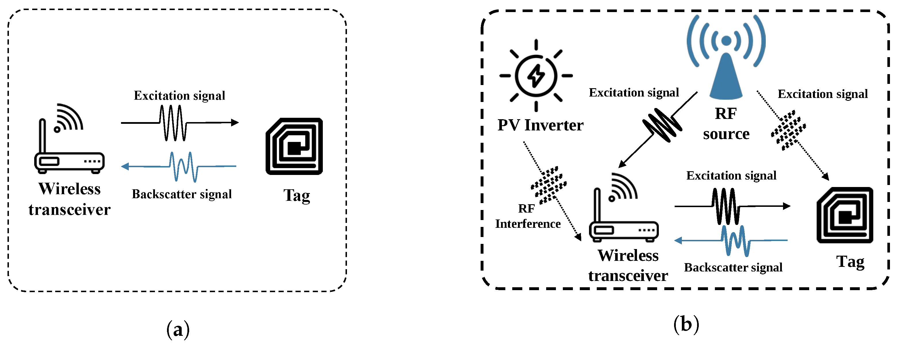
15] further emphasized that unstable inverter data feedback reduces grid efficiency—these studies highlight the need for low-cost wireless solutions. Backscatter technology addresses this limitation by enabling battery-free real-time sensing through ambient RF energy harvesting, thus facilitating flexible low-cost wireless deployment and reducing both installation and maintenance costs, as shown in
Figure 1.
However, the nature of reusing ambient carriers makes the scattered signals more susceptible to variances in the ambient carriers. The power gap between the scattered signals and the ambient carriers, which is caused by the loss of the scattering process, makes the demodulation under the carriers’ influence even more difficult. In distributed PV environments, inverter switching and control circuits generate narrowband emissions near the 900 MHz ISM band, which can exceed the tag-reflection power by tens of decibels. Based on link-budget estimation, a cancellation depth of roughly 40 dB is required to restore receiver sensitivity and maintain reliable tag detection.
Various attempts have been made to overcome this interference, including leveraging ambient wireless signals and optimizing adaptation to mainstream communication technologies [
16,
17,
18]. Additional efforts focus on optimizing signal-modulation schemes and receiver configurations to mitigate interference [
19,
20,
21]. Yet all these approaches mainly focus on avoiding the interference rather than countering it, thus resulting in spectral wastage and making large-scale deployment impractical. Contrary to their insights, we intend to overcome the carrier interference from a more fundamental aspect, which is to directly cancel the interference when the RF signal reaches the front-end with hardware and embedded system design.
Different from traditional self-interference-cancellation approaches in full-duplex radios which cancel the interference from themselves [
22], we intend to cancel the interference from the ambient carrier source, therefore incurring various challenges in:
(i) Filtering out the carrier from the received ambient signals. The ambient signals are often accompanied by various interference components, which affect the reception of the carrier and degrade communication performance. Therefore, our ACIC system should be capable of extracting the carrier.
(ii) Performing interference cancellation on the carrier. Interference caused by the carrier can severely affect weak scattered signals. Consequently, our ACIC system needs to reduce the interference to the level of the scattered signals.
(iii) Enhancing the real-time performance of the cancellation. Ensuring seamless operation in dynamic PV environments is essential for communication, requiring our ACIC system to implement an acceleration algorithm for faster system response.
To address these challenges, we propose the first Ambient Carrier Interference Cancellation (ACIC) system that introduces the following techniques. First, we employ filters to extract the carrier component from the received ambient signals. Inspired by classical carrier interference-cancellation designs [
22,
23], we use high-precision programmable phase shifters and attenuators to achieve carrier cancellation. Additionally, to ensure real-time cancellation, we utilize an adaptive local search algorithm for rapid parameter adjustment.
We implement the system with a highly integrated hardware design and a high-efficiency signal-processing algorithm. Then, we conduct comprehensive experiments to evaluate the ACIC circuit. Results demonstrate that the ACIC system achieves a cancellation of greater than 40 dB at 900 MHz, both with and without a backscatter tag. At sensor data rates of 1–50 kbps and 0.1 m distance, this cancellation reduces bit error rate (BER) from 0.3 to 0.001, and at 0.5 m distance, it reduces BER from 0.5 to 0.03, ensuring reliable transmission. The main contributions are summarized as follows:
We design the first ACIC system for backscatter.
We implement and evaluate the ACIC in real-world environments using an off-the-shelf backscatter tag. Our experiments verify the feasibility and compatibility of the ACIC system.
The paper is organized as follows. We review the related work in
Section 2. In
Section 3, we introduce the main differences between our ACIC system and other wireless communication methods. In
Section 4, we describe the design of the ACIC system. In
Section 5, the demonstration circuit implementation is presented. In
Section 6, our ACIC system is evaluated with cancellation results. Then, we discuss the further research in
Section 7. Finally, the conclusions are drawn in
Section 8.
2. Related Work
Key performance indicators of existing interference-cancellation solutions are summarized in
Table 1, which focuses on three core metrics: solution type, cancellation method, cancellation depth, and spectrum efficiency.
The table covers typical interference-cancellation schemes for backscatter communication and indirectly reflects the performance gap of self-interference-cancellation solutions in low-power scenarios. It clearly shows that most existing schemes either lack sufficient cancellation depth or sacrifice spectrum efficiency, laying a foundation for the subsequent classified analysis of related work. The related work can be classified into interference cancellation for backscatter and self-interference cancellation in full-duplex.
Interference cancellation for backscatter. In backscatter communication, interference cancellation is mostly achieved by avoiding interference to ensure communication effectiveness. For example, ref. [
16] adopts a frequency-shift scheme based on LET signals, embedding data through phase modulation. Ref. [
24] proposes a method of converting error vectors into reverse-scattered frames, relying on the channel to achieve in-band backscatter communication. However, these methods require additional resources and are impractical for large-scale deployment. Recent backscatter interference-cancellation schemes have further explored adaptive or scenario-specific optimization. Ref. [
29] develops a harmonic interference-resilient solution using adaptive pulse-width frequency shifting, achieving 35 dB cancellation for harmonic interference common in PV inverter systems, but it still depends on frequency adjustment rather than active cancellation. Ref. [
30] designs an edge intelligent dual-function backscatter system, integrating edge computing to optimize interference detection, but its 32 dB cancellation depth is insufficient for 40 dB PV inverter interference. RFID already has mature cancellation solutions [
27,
31], specifically designed to achieve high interference isolation through self-interference compensators. However, unlike RFID, backscatter communication requires higher adaptability to dynamic environments, whereas RFID focuses on enhancing the sensitivity of the reader.
Self-interference cancellation in full-duplex. Ref. [
22] has improved the self-interference-cancellation effect in full-duplex, thus achieving a theoretical throughput doubling. However, our ACIC system does not require such a high level of cancellation. Instead, we have optimized it for power consumption and real-time performance. Another representative full-duplex self-interference-cancellation method is antenna isolation-based mitigation [
32], which reduces interference by 25–30 dB through rational antenna layout adjustment, but it requires strict spatial constraints, making it incompatible with miniaturized backscatter tags in PV systems.
3. Motivation
In backscatter communication, the interference caused by carrier signals on scattered signals is a fundamental issue. It should be noted that when the carrier signal is reused, the reception and identification of scattered signals can be more difficult than in other wireless communication methods. Without a doubt, techniques that avoid interference, such as frequency hopping, can effectively address interference issues. However, they may lead to spectral congestion and reduced efficiency under the limited 902–928 MHz ISM band, particularly for large-scale PV deployments. Therefore, we propose an in-band solution, ACIC, which focuses on interference elimination.
In distributed PV environments, inverter switching and control circuits generate continuous narrowband emissions near the 900 MHz band, which can be tens of decibels stronger than the tag reflections after propagation and reflection losses. Based on link-budget analysis and measured signal strength, a cancellation depth of approximately 40 dB is required to restore receiver sensitivity and ensure reliable tag detection.
What makes our design different from traditional self-interference cancellation? ACIC does not generate a carrier; instead, it receives the ambient signals and extracts the carrier. Moreover, our requirements for interference elimination are not as stringent as those in full-duplex communication. Compared with full-duplex radios, which must suppress self-interference often exceeding 100 dB due to simultaneous transmission and reception on the same antenna, ACIC faces a less stringent requirement because the ambient carrier originates externally and is relatively stable in amplitude and phase, while full-duplex communication typically requires self-interference suppression that exceeds the background noise by 110 dB. Once we achieve interference cancellation to the level of reflected signals, we focus more on power consumption and real-time performance. Therefore, we only employ analog-domain interference cancellation without digital processing.
4. Design
In this section, we describe the design of ACIC, which strikes a balance between interference cancellation, low power consumption, and real-time performance when compared to conventional communications adapted for backscatter communication. The ACIC system comprises a filter and an interference-cancellation circuit.
4.1. Carrier Detecting Scheme
When receiving ambient carriers, signals are often accompanied by other interference components. Therefore, carrier extraction is crucial. In the design of ACIC, we start with a single carrier for testing. Here, we employ a filter to detect and filter out the single carrier signal at 900 MHz from the received ambient signals. Specifically, we adopt a bandpass filter with a center frequency of 900 MHz. This filter is selected for its low insertion loss and high out-of-band rejection, ensuring effective cancellation of out-of-band interference while extracting the target carrier.
4.2. Interference in Backscatter
Although the carrier is known, some noise is often introduced during transmission. Therefore, it is difficult to get identical signals to cancel out the interference.
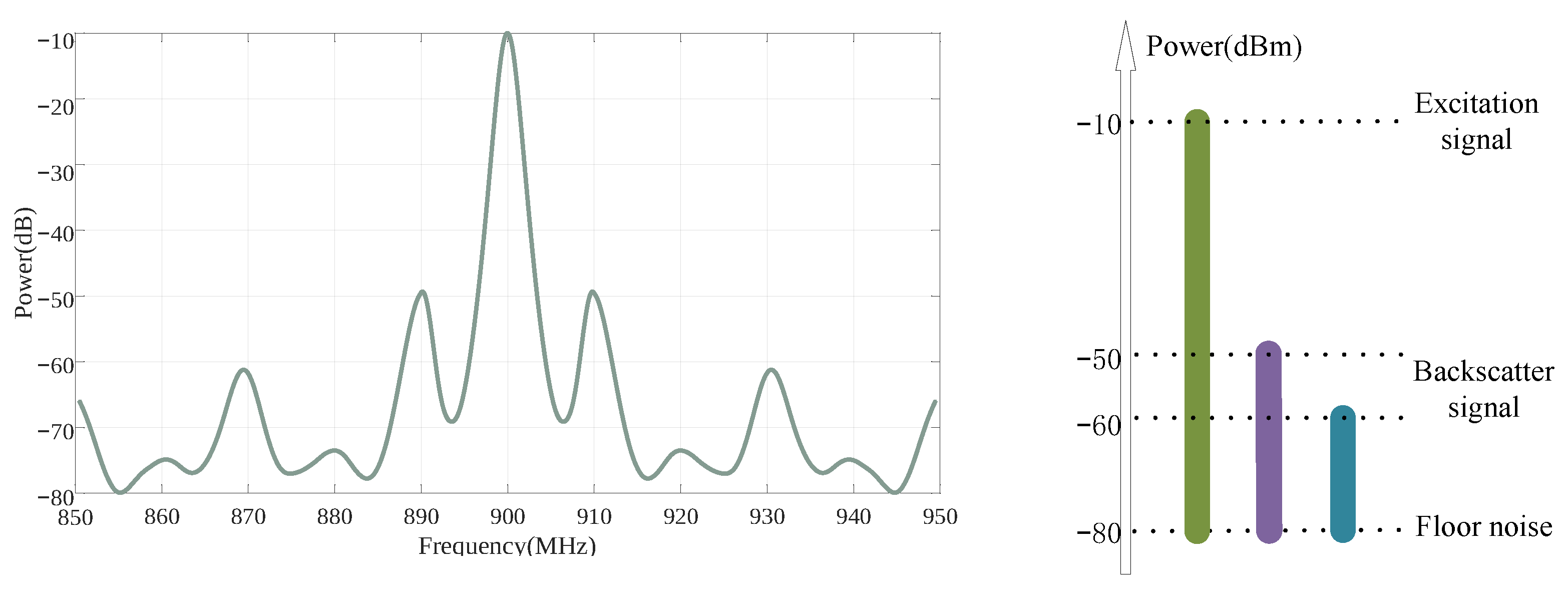
Figure 2 illustrates the signals without interference cancellation in backscatter. As can be seen from the figure, the strength of the interference signal is −10 dB, while the reflected signal is on the order of −50 dB and smaller. Such a difference in intensity greatly increases the difficulty of the demodulation process. Without addressing the interference, the demodulation algorithm and detection performance face high demands, leading to a waste of computational power and resources. Therefore, ACIC should have a cancellation capability of at least 40 dB to reduce the interference to a level of the reflected signal.
4.3. Interference-Cancellation System
Existing carrier-cancellation solutions include both analog and digital approaches. However, digital cancellation relies on high-performance digital signal processors and precise signal synchronization, which are difficult to achieve in backscatter. Analog cancellation, on the other hand, can be divided into spatial and RF interference-cancellation methods.
Spatial interference cancellation: We use a circulator as the isolation component in a single-antenna solution to accommodate a broader range of scenarios. A circulator is a three-port microwave element that isolates the transmit signal from the receive signal, thereby reducing direct-path interference.
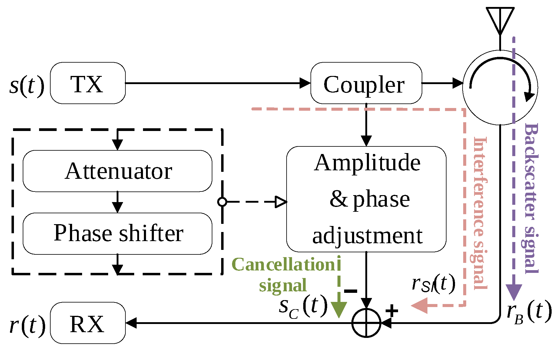
RF interference cancellation: Figure 3 shows a classical RF interference-cancellation scheme. From the TX terminal, a signal is coupled out and undergoes adjustments in parameters such as amplitude and phase to reconstruct a signal complementary to the interference signal (cancellation signal). Subsequently, the cancellation signal is added to the interference signal to achieve cancellation.
When reconstructing the cancellation signal, it is necessary to take into account the channel characteristics experienced by the interference signal. The signal from the TX terminal to the RX terminal mainly passes through a coupler and a circulator, covering a short distance and exhibiting stable channel characteristics. Thus, the interference channel can be considered as a constant reference channel, where the signal experiences constant amplitude attenuation and constant time delay. If the signal at the TX terminal is
, then the interference signal can be expressed as:
where
and
stand for the transmission delay and amplitude attenuation factor of the interference channel.
In order to generate the cancellation signal, the signal
is split using a coupler, and the signal opposite to the interference signal is obtained by adjusting the amplitude and phase. The adjustment of amplitude and phase is achieved in the actual circuit using an attenuator and a phase shifter. The cancellation signal can be expressed as:
where
and
are the amplitude decay factor and time delay of the cancellation signal, and
is the phase change.
Therefore, the signal
at the RX terminal is:
where
is the signal reflected from the label (Backscatter signal) and
is the noise.
is often several orders of magnitude larger than
, achieving effective interference cancellation is therefore particularly important. The interference-cancellation capability G(dB) is defined in the literature [
32]:
where
is the energy of the interference signal,
is the noise energy, and
is the energy of the residual interference signal
.
After calculation, it can be seen that the interference-cancellation capability G is strongest when is equal to , is equal to , and the phase change meets .
As a result, we designed an adaptive interference-cancellation circuit with an RF section, as shown in
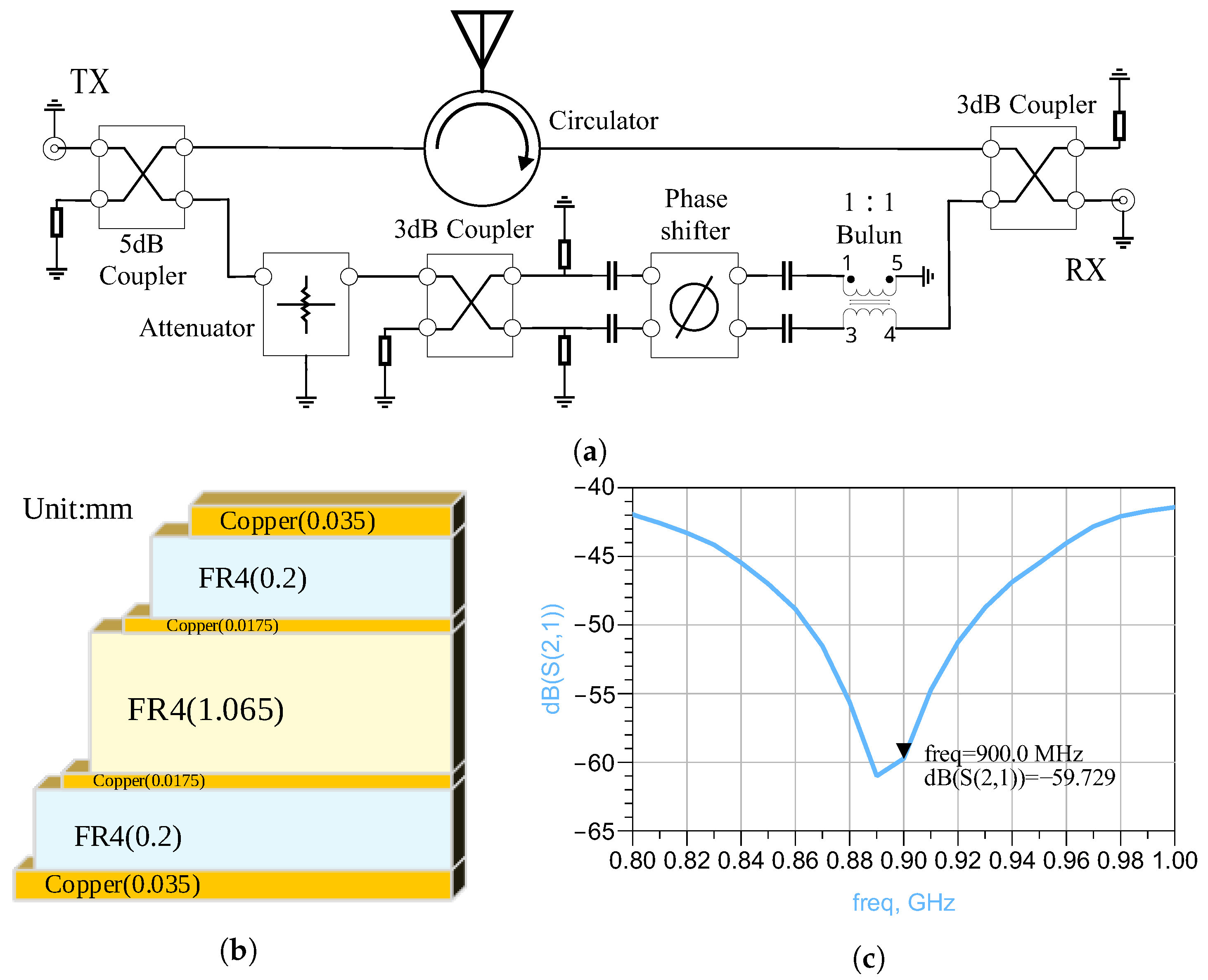
Figure 4a. The signal enters from the TX terminal and is divided into two RF signals by a 5 dB coupler. The main circuit signal is transmitted from the antenna through the circulator. However, due to the insufficient isolation of the circulator, a high power residual signal remains at the RX terminal. The branch circuit signal is amplitude modulated by an attenuator and phase shifted to generate a cancellation signal, which cancels out the interference signal.
The circuit’s stacked structure is a conventional four-layer board, and the dielectric materials are all FR-4. Using the official S-parameter models of each device, the simulation results shown in
Figure 4c indicate that a theoretical interference cancellation of nearly 60 dB can be achieved at 900 MHz.
To ensure the reliability of the results, we also simulate the effect of the attenuator under different stack configurations. By comparing the stacked configurations of their evaluation boards with the conventional stacked configurations (shown in
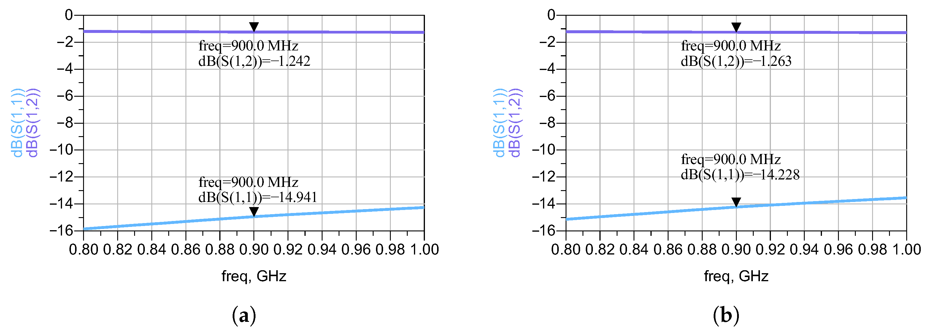
Figure 4b), we find that the main difference lies in the dielectric materials, RO4350 and FR-4. The results in
Figure 5 indicate that the S12 and S21 parameters of both configurations are not significantly different, and their transmission characteristics are more consistent.
4.4. Acceleration Algorithm
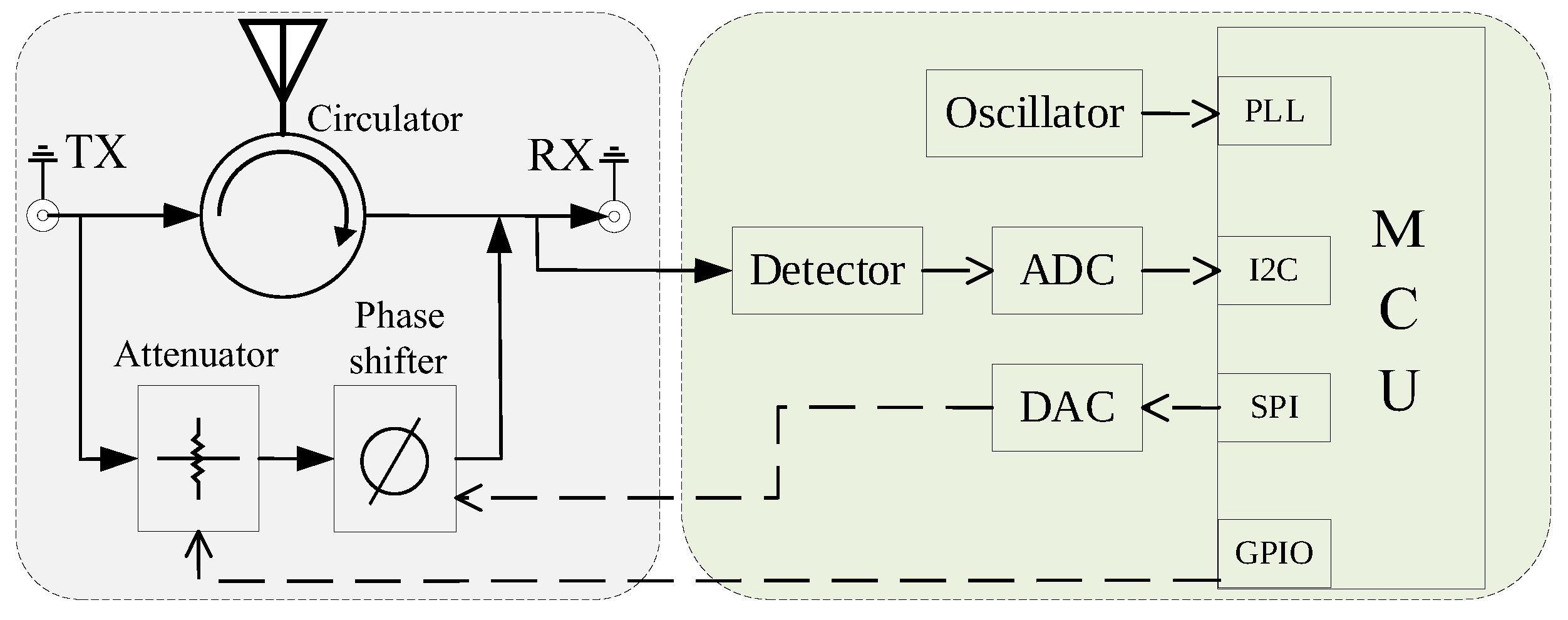
For the cancellation circuit, we also need efficient control algorithms to manage parameters such as attenuation value and phase shift value. In particular, we add a detector at the RX terminal of the RF circuit to achieve closed-loop control. The schematic of the closed-loop control for the interference-cancellation module is illustrated in
Figure 6. The crystal and internal phase-locked loop (PLL) provide the clock signal. The MCU uses GPIO to control the attenuator, SPI protocol to communicate with the DAC to control the phase shifter, and I2C to communicate with the ADC to read the feedback signal from the detector.
We use a local search Algorithm 1 combined with a feedback signal to implement closed-loop control for ACIC, which enhances the speed of the cancellation.
| Algorithm 1 Local search |
Input: None;
Output: None;
- 1:
Program initialization. - 2:
Turn off the reference source. - 3:
Assign values to the parameters of the attenuator and the phase shifter. - 4:
Sample data using a detector. - 5:
while power measurement value >= set threshold do - 6:
Invoke the local search algorithm to find new phase shift values. - 7:
Assign values to the parameters of the attenuator and the phase shifter. Sample data using a detector. - 8:
end while - 9:
return None.
|
Through the optimization of the acceleration algorithm, the interference-cancellation module improves its adaptability to different environments and enhances its anti-interference ability to ensure the effective cancellation. In addition, the algorithm enhances the real-time performance of the cancellation.
5. Implementation
Figure 7 depicts the interference-cancellation circuit, which is divided into left and right sections. The right half comprises the digital and power supply components, while the left half consists of the RF components. The RF section mainly includes an attenuator, phase shifter, detector, circulator and several couplers. Among these components, the attenuator HMC1119 has an attenuation range of 0–31.5 dB, with a step value of 0.25 dB; the phase shifter ADL5390 has a phase shift range of 360°, with an accuracy better than 1°; the detector AD8313 has a linear range of 62 dB; and the couplers X3C09P1 all have a power tolerance of over 70 W. The MCU is AGLN060, a nano-low-power FPGA capable of meeting the basic control requirements.
The adaptive tuning algorithm performs iterative adjustment of the phase and attenuation settings based on the detector output. Each iteration completes within a few microseconds, and convergence is typically achieved within several tens of iterations. The tuning cycle runs in the background without affecting tag demodulation, and the control loop consumes less than 1 mW additional power.
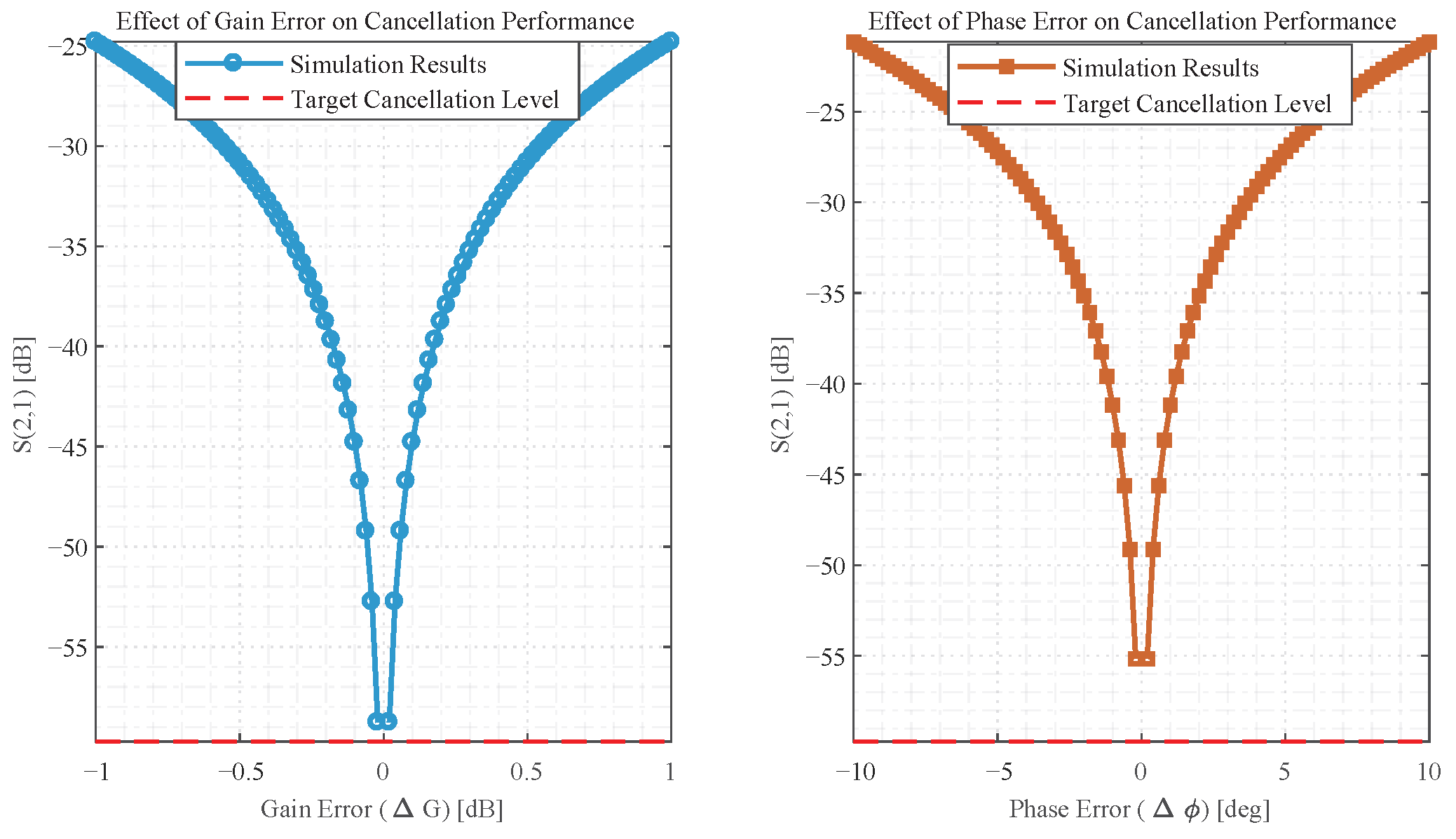
A sensitivity analysis is conducted to evaluate the impact of small amplitude and phase deviations on cancellation performance. These errors are induced by temperature swings or vibration in distributed PV deployments, which alter key component parameters and further impact cancellation depth. Results are shown in
Figure 8. Phase errors of ±1° and amplitude errors of ±0.1 dB are found to reduce cancellation depth by approximately 10 dB. Even with these reductions, the minimum cancellation depth remains above −47 dB, well exceeding the 40 dB requirement for reliable backscatter communication in PV systems. This confirms ACIC sustains effective interference cancellation under real-world environmental disturbances.
6. Evaluation
In this section, we first test the actual attenuation and phase-shifting effects. Then, we test the effect of the ACIC system using a single carrier. Finally, we deploy the ACIC system in a backscatter test scenario for the experiment.
6.1. Component Testing
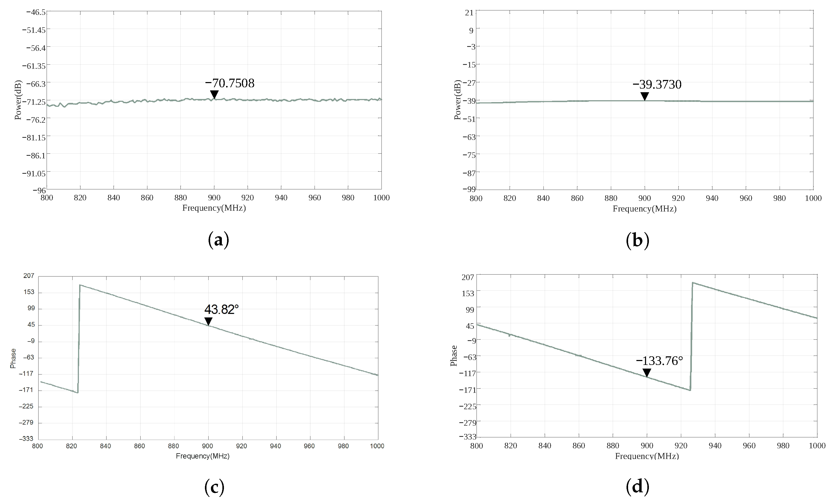
Before conducting an experimental test on the system, we assess the actual performance of the attenuator and the phase shifter. The actual attenuation performance is depicted in
Figure 9a,b, where the minimum and maximum attenuation levels reach 31 dB, closely aligning with the theoretical value of 31.5 dB. Additionally, the comparison between 0° and 180° phase shift values is presented in
Figure 9c,d, revealing an actual phase shift value of 177°. The accuracy of both devices meets our expectations.
6.2. ACIC Testing
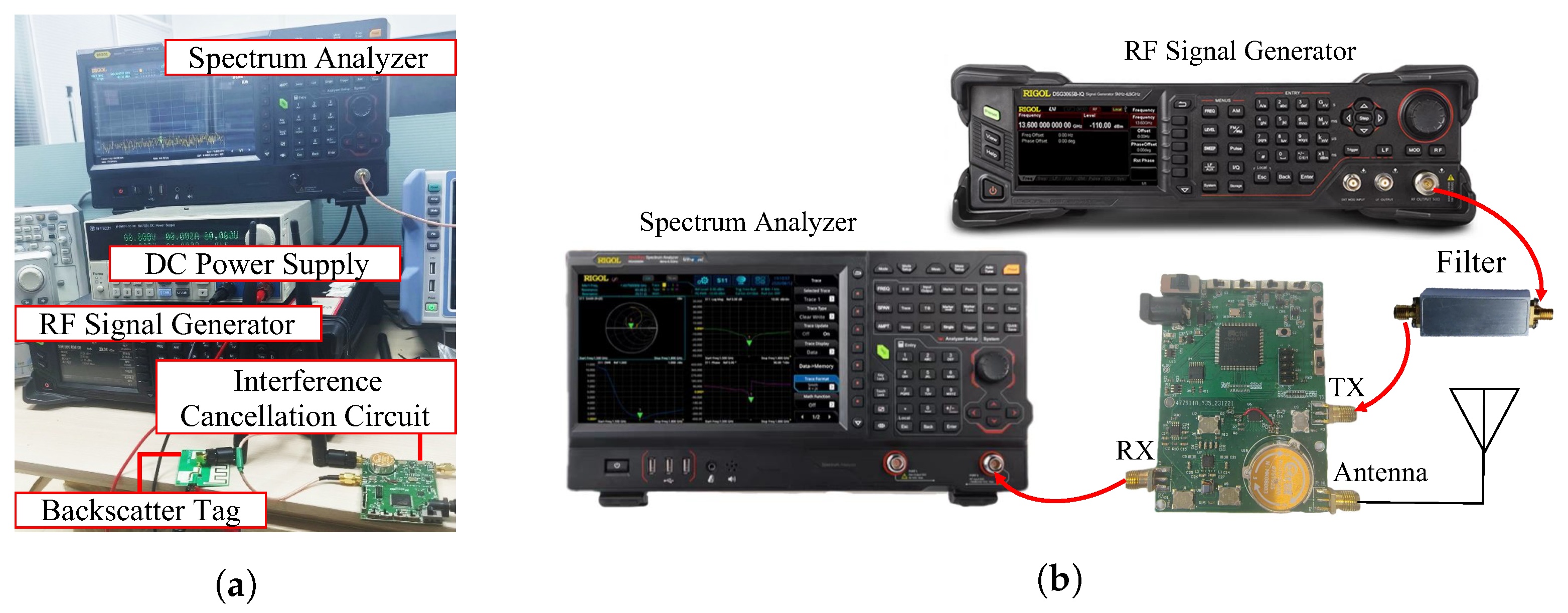
We construct an experimental testbed as shown in
Figure 10. A RIGOL RF Signal Generator (RF-Lambda, Carrollton, TX, USA) generates a 900 MHz signal with 0 dB power, along with some small signals at other frequencies. A RIGOL Spectrum Analyzer (RIGOL Technologies, Gilching, Germany) reads the power at the RX terminal of the interference-cancellation circuit. By using the filter, we can detect and filter out the carrier.
6.2.1. Cancellation Performance
The scheme of the single carrier test is illustrated in
Figure 10b, where the carrier is filtered and received by the circuit, and the cancelled signal is output from the RX terminal. In this programme, the signal at the RX terminal should ideally approach the noise level.
We assess the power of the interference signal under three conditions: first, in the absence of power supply, when the active RF attenuator and phase shifter can not form a path and thus no cancellation signal is present, the power of the interference signal can be measured as ; second, with power supply present, the power of the residual interference signal can be measured as ; third, the attenuator-attenuation value is set to the maximum, the power of the interference signal can be measured as .
The test results are shown in
Figure 11, and the powers for the three cases are:
= −27.09 dB,
= −71.02 dB, and
= −27.43 dB. The cancellation effect is 43 dB.
6.2.2. Tag Influence
To quantify the impact of backscatter tags on ACIC performance, we compared cancellation depth with/without a commercial backscatter tag. We use a backscatter tag to generate the reflected signal. As shown in
Figure 12, the power of the 900 MHz signal before and after cancellation measures −13.65 dB and −60.06 dB, respectively, resulting in a cancellation effect of 46 dB. It is noteworthy that this cancellation level is comparable to the harmonic level. The results confirm that ACIC is compatible with backscatter tags and maintains stable performance in tag-equipped scenarios.
6.2.3. Communication Performance
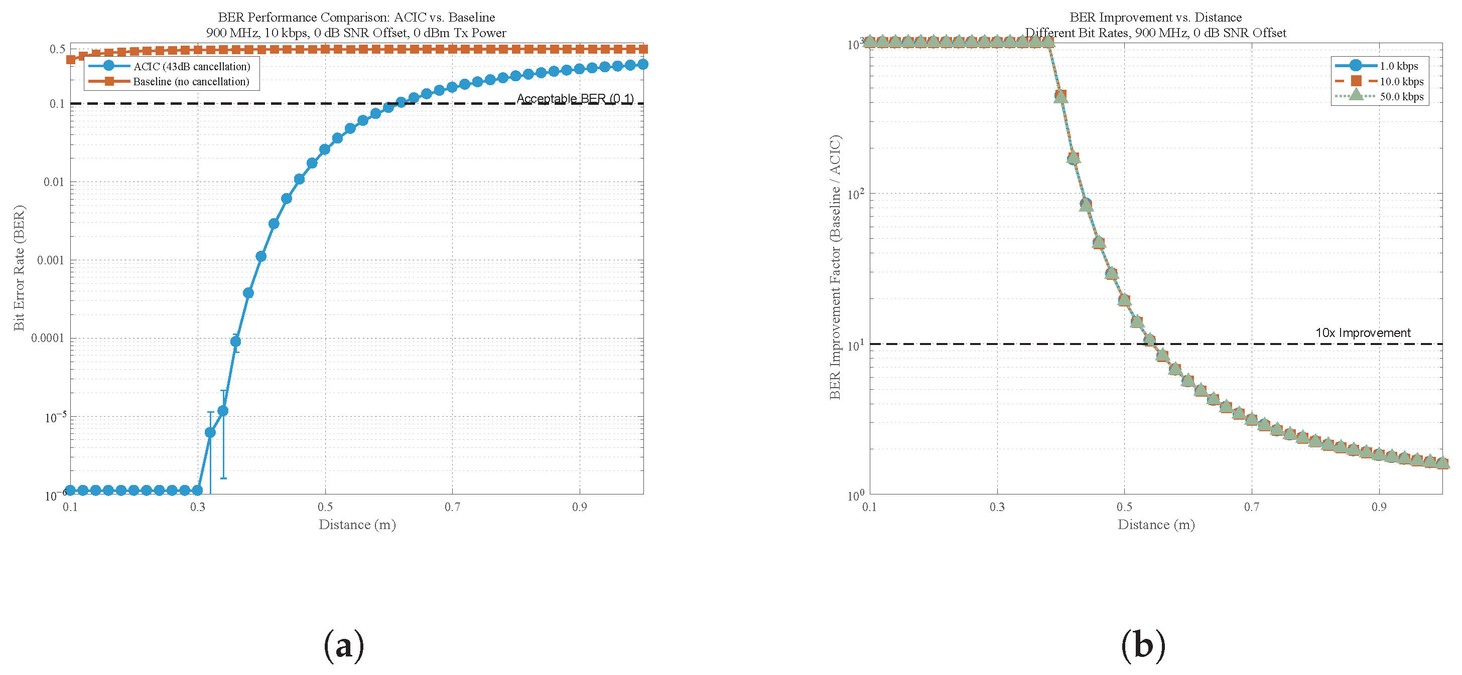
To quantify how the interference cancellation translates to real backscatter communication quality, we conduct BER tests under the same 900 MHz frequency band. The test conditions are standardized as follows: 0 dBm transmit power, additive white Gaussian noise (AWGN) with 0 dB SNR offset, and data rates of 1.0 kbps, 10.0 kbps, and 50.0 kbps, covering typical backscatter sensor data rates in PV systems. We compare the BER performance of the ACIC-equipped system against a baseline.
Figure 13a presents the BER variation with communication distance for the ACIC system and the baseline. At 0.1 m, the baseline system has a BER of approximately 0.3, while the ACIC-equipped system maintains a BER below 0.001. When distance increases to 0.5 m, the baseline BER rises to around 0.5, but the ACIC system’s BER only reaches approximately 0.03, remaining well below the reliable transmission limit.
Figure 13b illustrates the BER improvement factor across different distances and data rates, further quantifying ACIC’s adaptability to varying PV sensor data requirements. All three data rates exhibit similar improvement trends. They maintain a 10× or higher improvement factor within a practical distance range, with peak improvement factors clustered around 20–25× at mid-range distances.
These BER results directly validate the practical value interference cancellation. By suppressing ambient carrier interference, ACIC not only meets the basic cancellation requirement but also significantly enhances backscatter communication reliability, reducing BER above 10×, extending the effective communication range of backscatter tags in PV environments, and adapting to diverse data rate needs.
7. Discussion
In our implementation, we conducted tests on the ACIC system using a single carrier, achieving satisfactory interference-cancellation results. However, the current system has limitations for practical distributed PV deployment, and further research is needed to address real-world ambient complexity and deployment challenges.
The ACIC system uses a filter and detector fixed at 900 MHz, which limits its ability to handle multi-carrier interference. Real PV sites often have coexisting ambient sources such as LTE signals, Wi-Fi and LoRa. These non-target carriers can interfere with 900 MHz carrier extraction and reduce cancellation stability. Additionally, the system’s performance under dynamic ambient conditions remains untested. Distributed PV inverter output fluctuates with sunlight and temperature, changing the amplitude and phase of narrowband emissions near 900 MHz. The current adaptive loop has not been tested under rapid interference fluctuations like sudden inverter load changes, and its response speed may not match PV operational dynamics.
To address these issues, future work will first focus on replacing the fixed 900 MHz bandpass filter with a reconfigurable filter bank that covers key frequency bands of coexisting ambient sources. Second, the single interference-cancellation path will be expanded to multiple independent paths to enable tailored amplitude and phase adjustment for each carrier. Third, a frequency tracking module will be added to monitor and respond to dynamic frequency shifts. When deviations are detected, the module will adjust filter and cancellation path parameters within microseconds to maintain stable cancellation.
Potential regulatory challenges for unlicensed band operation also require consideration. ACIC generates cancellation signals to counter ambient carriers. These signals’ emission in unlicensed bands such as the 902–928 MHz ISM band must comply with local spectrum regulations. Future work will test cancellation signal spectral masks to ensure compliance with unlicensed band power limits, avoiding interference to other legal wireless devices.
Nevertheless, there is potential for further research into the system, particularly concerning the complexity of ambient carriers.
8. Conclusions
We design and validate our ACIC system, which strikes a balance between interference cancellation, low power consumption, and real-time performance adapted for backscatter communication. The experimental results show that our system achieves greater than 40 dB interference cancellation, both with and without a backscatter tag, while BER are reduced above 10× compared to baselines. This performance demonstrates its potential to support distributed PV deployments requiring low-power and cost-efficient communication solutions.
The above results are obtained under controlled conditions, verifying core functionality. And the 40 dB cancellation satisfies the practical requirements for reliable tag detection in distributed PV deployments. Fluctuating inverter emissions and coexisting non-target carriers may affect cancellation performance, which motivates further optimization of the algorithm. Future research will focus on enhancing multi-carrier suppression and improving the system’s adaptability to dynamic interference conditions.
Author Contributions
Conceptualization, X.L. and Y.W.; methodology, Y.W.; software, Y.W.; validation, X.L., X.X., G.Z., W.D., Y.C., Q.L. and Y.W.; formal analysis, Y.W.; investigation, X.L., X.X. and G.Z.; resources, W.D., Y.C. and Q.L.; data curation, X.L.; writing- original draft preparation, Y.W., D.C. and W.W.; writing—review and editing, Y.W., D.C. and W.W.; visualization, X.L.; supervision, D.C. and W.W.; project administration, X.L. and Y.W.; funding acquisition, X.L. All authors have read and agreed to the published version of the manuscript.
Funding
This work was supported in part by Science and Technology Project of Guizhou Power Grid Co., Ltd. under Grant No. 060000KC24100003, and National Natural Science Foundation of China with Grant 62471194.
Data Availability Statement
The data presented in this study are available in the article.
Conflicts of Interest
Authors Xu Liu, Xiaobing Xiao, Guanghui Zhang, Wu Dong, Yongxiang Cai and Qing Liu were employed by the company Guizhou Power Grid Co. Ltd. The remaining authors declare that the research was conducted in the absence of any commercial or financial relationships that could be construed as a potential conflict of interest.
References
- Wang, W.; He, S.; Sun, L.; Jiang, T.; Zhang, Q. Cross-Technology Communications for Heterogeneous IoT Devices Through Artificial Doppler Shifts. IEEE Trans. Wirel. Commun. 2019, 18, 796–806. [Google Scholar] [CrossRef]
- He, S.; Ma, W.; Dong, H.; Xiao, L.; Jiang, T. C-Cube: Rethinking Distributed Beamforming for Concurrent Charging in Backscatter Networks. Proc. ACM Interact. Mob. Wearable Ubiquitous Technol. 2022, 6, 203:1–203:26. [Google Scholar] [CrossRef]
- Huang, Q.; Song, G.; Wang, W.; Dong, H.; Zhang, J.; Zhang, Q. FreeScatter: Enabling Concurrent Backscatter Communication Using Antenna Arrays. IEEE Internet Things J. 2020, 7, 7310–7318. [Google Scholar] [CrossRef]
- Xiao, F.; Zhang, S.; Tang, S.; Shen, S.; Dong, H.; Zhong, Y. WiSion: Bolstering MAV 3D Indoor State Estimation by Embracing Multipath of WiFi. IEEE Trans. Veh. Technol. 2023, 72, 253–266. [Google Scholar] [CrossRef]
- Dong, H.; Kuang, W.; Xiao, F.; Liu, L.; Xiang, F.; Wang, W.; He, J. Ultra-low-power backscatter-based software-defined radio for intelligent and simplified IoT network. Front. Inf. Technol. Electron. Eng. 2022, 23, 19–30. [Google Scholar] [CrossRef]
- Dong, H.; Wu, Y.; Li, F.; Kuang, W.; He, Y.; Zhang, Q.; Wang, W. PassiveBLE: Towards Fully Commodity-Compatible BLE Backscatter. arXiv 2025, arXiv:2503.11490. [Google Scholar]
- Luo, Z.; Li, W.; Wu, Y.; Dong, H.; Bian, L.; Wang, W. Accurate Indoor Localization for Bluetooth Low Energy Backscatter. IEEE Internet Things J. 2025, 12, 1805–1816. [Google Scholar] [CrossRef]
- Dong, H.; Xie, Y.; Zhang, X.; Wang, W.; Zhang, X.; He, J. GPSMirror: Expanding Accurate GPS Positioning to Shadowed and Indoor Regions with Backscatter. In Proceedings of the 29th Annual International Conference on Mobile Computing and Networking, Madrid, Spain, 2–6 October 2023; pp. 1–15. [Google Scholar]
- Zhang, S.; Wang, W.; Tang, S.; Jin, S.; Jiang, T. Robot-Assisted Backscatter Localization for IoT Applications. IEEE Trans. Wirel. Commun. 2020, 19, 5807–5818. [Google Scholar] [CrossRef]
- Wang, W.; Yang, L.; Zhang, Q.; Jiang, T. Securing On-Body IoT Devices By Exploiting Creeping Wave Propagation. IEEE J. Sel. Areas Commun. 2018, 36, 696–703. [Google Scholar] [CrossRef]
- Huang, Y.; Wang, W.; Wang, H.; Jiang, T.; Zhang, Q. Authenticating On-Body IoT Devices: An Adversarial Learning Approach. IEEE Trans. Wirel. Commun. 2020, 19, 5234–5245. [Google Scholar] [CrossRef]
- Hussain, T.; Gil, I.; Fernández-García, R. Wearable displacement sensor using inductive coupling of printed RFID tag with metallic strip. Electronics 2025, 14, 262. [Google Scholar] [CrossRef]
- Yuan, J.; Sun, S.; Zhang, W.; Xiong, M. The economy of distributed PV in China. Energy 2014, 78, 939–949. [Google Scholar] [CrossRef]
- Wu, Y.; Xu, M.; Tao, Y.; He, J.; Liao, Y.; Wu, M. A Critical Barrier Analysis Framework to the Development of Rural Distributed PV in China. Energy 2022, 245, 123277. [Google Scholar] [CrossRef]
- Li, F.; Ding, J.; Zhou, C.; Yong, W.; Huang, Y.; Wang, J.; Xu, X. Key Technologies of Large-scale Grid-connected Operation of Distributed Photovoltaic Under New-type Power System. Power Syst. Technol. 2024, 48, 184–196. [Google Scholar]
- Chi, Z.; Liu, X.; Wang, W.; Yao, Y.; Zhu, T. Leveraging ambient lte traffic for ubiquitous passive communication. In Proceedings of the Annual Conference of the ACM Special Interest Group on Data Communication on the Applications, Technologies, Architectures, and Protocols for Computer Communication, Virtual, 10–14 August 2020; pp. 172–185. [Google Scholar]
- Dunna, M.; Meng, M.; Wang, P.H.; Zhang, C.; Mercier, P.; Bharadia, D. {SyncScatter}: Enabling {WiFi} like synchronization and range for {WiFi} backscatter Communication. In Proceedings of the 18th USENIX Symposium on Networked Systems Design and Implementation (NSDI 21), Boston, MA, USA, 12–14 April 2021; pp. 923–937. [Google Scholar]
- Zhang, P.; Josephson, C.; Bharadia, D.; Katti, S. Freerider: Backscatter communication using commodity radios. In Proceedings of the 13th International Conference on Emerging Networking Experiments and Technologies, Seoul, Republic of Korea, 12–15 December 2017; pp. 389–401. [Google Scholar]
- Du, C.; Liu, J.; Wang, S.; Zhang, R.; Gong, W.; Yu, J. Timespan-based Backscatter Using a Single COTS Receiver. In Proceedings of the 21st Annual International Conference on Mobile Systems, Applications and Services, Helsinki, Finland, 18–22 June 2023; pp. 450–461. [Google Scholar]
- Liu, X.; Chi, Z.; Wang, W.; Yao, Y.; Hao, P.; Zhu, T. Verification and redesign of {OFDM} backscatter. In Proceedings of the 18th USENIX Symposium on Networked Systems Design and Implementation (NSDI 21), Boston, MA, USA, 12–14 April 2021; pp. 939–953. [Google Scholar]
- Yu, J.; Du, C.; Liu, J.; Zhang, R.; Wang, S. SubScatter: Subcarrier-Level OFDM Backscatter. In Proceedings of the IEEE INFOCOM 2023-IEEE Conference on Computer Communications, New York, NY, USA, 17–20 May 2023; IEEE: Piscataway, NJ, USA, 2023; pp. 1–10. [Google Scholar]
- Bharadia, D.; McMilin, E.; Katti, S. Full duplex radios. In Proceedings of the ACM SIGCOMM 2013 Conference on SIGCOMM, Hong Kong, China, 12–16 August 2013; pp. 375–386. [Google Scholar]
- Zhang, J.; He, F.; Li, W.; Li, Y.; Wang, Q.; Ge, S.; Xing, J.; Liu, H.; Li, Y.; Meng, J. Self-interference cancellation: A comprehensive review from circuits and fields perspectives. Electronics 2022, 11, 172. [Google Scholar] [CrossRef]
- Kim, T.; Lee, W. Channel independent Wi-Fi backscatter networks. In Proceedings of the IEEE INFOCOM 2019-IEEE Conference on Computer Communications, Paris, France, 29 April–2 May 2019; IEEE: Piscataway, NJ, USA, 2019; pp. 262–270. [Google Scholar]
- Xiao, F.; Kuang, W.; Dong, H.; Wang, Y. Backscatter-Assisted Collision-Resilient LoRa Transmission. Sensors 2022, 22, 4471. [Google Scholar] [CrossRef]
- Zhang, K.; Cao, Z.; Dong, H.; Luo, Z.; Bian, L.; Wang, W. Design and Implementation of NOMA Backscatter Communication with Low-Precision Oscillators. J. Commun. Inf. Netw. 2024, 9, 286–295. [Google Scholar] [CrossRef]
- Forouzandeh, M.; Karmakar, N. Self-interference cancelation in frequency-domain chipless RFID readers. IEEE Trans. Microw. Theory Tech. 2019, 67, 1994–2009. [Google Scholar] [CrossRef]
- Cheng, D.; Wu, F.; Zhang, C.; Liu, Y. Adaptive Multi-Source Ambient Backscatter Communication Technique for Massive Internet of Things. Electronics 2025, 14, 1532. [Google Scholar] [CrossRef]
- Liu, X.; Dong, W.; Yan, B.; He, X.; Peng, L.; Chen, X.; Chen, D.; Wang, W. Harmonic Interference Resilient Backscatter Communication with Adaptive Pulse-Width Frequency Shifting. Electronics 2025, 14, 946. [Google Scholar] [CrossRef]
- Zhou, W.; Zhang, Y.; Chen, X.; Wu, J. Edge-Intelligent Dual-Function Backscatter for Secure Tag-to-Tag Communication in IoT. Sensors 2022, 22, 4345. [Google Scholar] [CrossRef]
- Forouzandeh, M.M.; Karmakar, N. Towards the improvement of frequency-domain chipless RFID readers. In Proceedings of the 2018 IEEE Wireless Power Transfer Conference (WPTC), Montreal, QC, Canada, 3–7 June 2018; IEEE: Piscataway, NJ, USA, 2018; pp. 1–4. [Google Scholar]
- Anderson, C.R.; Krishnamoorthy, S.; Ranson, C.G.; Lemon, T.J.; Newhall, W.G.; Kummetz, T.; Reed, J.H. Antenna isolation, wideband multipath propagation measurements, and interference mitigation for on-frequency repeaters. In Proceedings of the IEEE SoutheastCon, Greensboro, NC, USA, 26–29 March 2004; IEEE: Piscataway, NJ, USA, 2004; pp. 110–114. [Google Scholar]
| Disclaimer/Publisher’s Note: The statements, opinions and data contained in all publications are solely those of the individual author(s) and contributor(s) and not of MDPI and/or the editor(s). MDPI and/or the editor(s) disclaim responsibility for any injury to people or property resulting from any ideas, methods, instructions or products referred to in the content. |
© 2025 by the authors. Licensee MDPI, Basel, Switzerland. This article is an open access article distributed under the terms and conditions of the Creative Commons Attribution (CC BY) license (https://creativecommons.org/licenses/by/4.0/).
