1. Introduction
Maglev transportation has the characteristics of high operating speed, contactless operation, high safety, strong terrain adaptability, and low vehicle maintenance costs. The maximum operating speed is expected to reach 600 km/h, and it may occupy an important position in the future transportation system [
1,
2]. There are various types of high-speed maglevs in the world, which can be divided into permanent magnet suspension, electromagnetic suspension (EMS), electrodynamic suspension (EDS), and superconducting pinning suspension, etc. [
3,
4,
5,
6,
7]. In addition, in order to reduce air resistance, vacuum tube high-speed maglev systems are also being studied [
8,
9]. Magnetic levitation technology is also applied in other fields, such as bearings, blood pumps, and space launch systems [
10,
11,
12].
High-speed maglev systems of different types are all linear synchronous motors. Linear synchronous motors can be used in fields that require linear transmission, such as manufacturing machinery, actuators, compressors, linear motion parts, roadway and railway transportation systems, and maglev systems [
13,
14,
15,
16,
17,
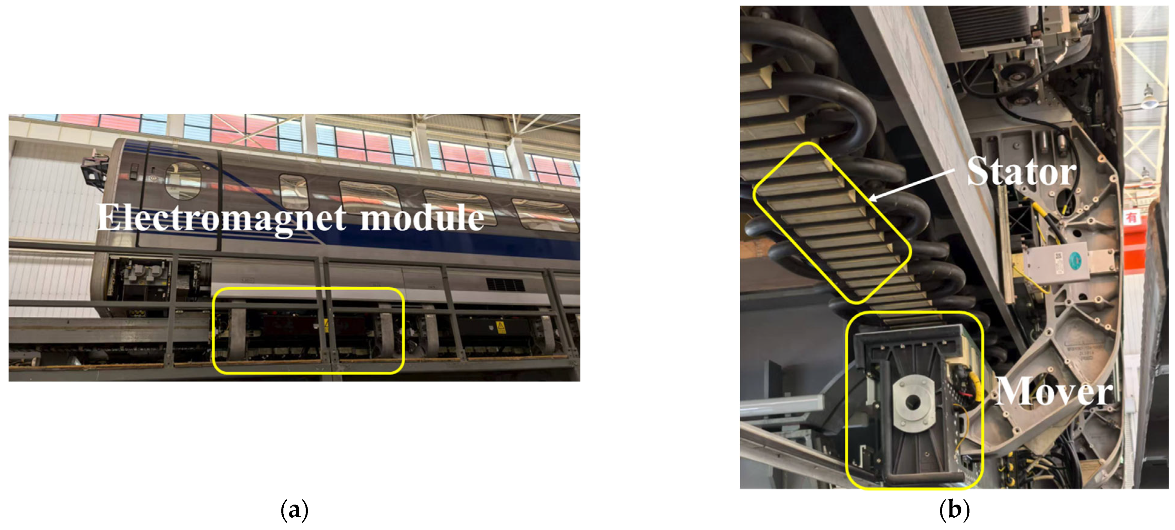
18]. Some components of the EMS system are shown in
Figure 1.
The linear synchronous motor is the core component of EMS-type maglev transportation, providing traction and suspension force for the maglev. Its performance directly determines the performance of the maglev transportation system. It is very crucial to study the performance of linear synchronous motors.
The magnetic field is the coupling field of the motor. Analyzing the motor magnetic field is of great significance to the research and improvement of motor performance. There are many methods for modeling and analyzing the magnetic field in the motor, including the equivalent circuit method, analytical method, finite element method, and data-driven method [
19]. The FEM can be used to evaluate and compare the performance of the proposed hybrid stator design against the conventional winding configuration in interior permanent magnet synchronous motors (IPMSMs) [
20]. For linear motors, analytical methods and the FEM can be used to analyze the impact of magnetic field spatial harmonics on their performance [
21]. The influence of the space–time harmonics of the air gap magnetic field on the torque ripple of the permanent magnet synchronous motor (PMSM) can be deduced by the Maxwell stress tensor [
22]. The magnetic field of EMS-type maglevs can be analyzed using the analytical method and FEM [
23]. The application of 2D-FFT can be used to study the relationship between the air gap flux density harmonic components and the electromagnetic force of the EMS-type maglev linear synchronous motor, as well as the generation mechanism of electromagnetic force ripple [
2]. The influence of the space–time harmonics of the air gap magnetic field on the torque and torque ripple of the PMAREL can be analyzed by combining the FEM with 2D-FFT [
24]. By calculating the vector magnetic potential, the temporal and spatial magnetic field distribution and its harmonics of the EDS type maglev can be derived, and the shape of the armature coil can be optimized [
25,
26]. For permanent magnet linear synchronous motors (PMLSMs), the analysis of the air gap magnetic flux density harmonics can be used to study the effect of magnetostriction on the normal force of the motor and thus analyze the vibration of the motor [
27]. Analysis of air gap magnetic flux density harmonics reveals their impact on iron losses and permanent magnet losses [
28,
29]. The influence of the PMSM air gap magnetic field on vibration and noise can be studied by analyzing the temporal and spatial harmonics [
30]. The same approach can also be applied to some new motors, such as analyzing the effect of slot–pole combinations on the magnetic field modulation performance, including torque ripple, of permanent magnet vernier machines (PMVMs) [
31].
The research above mainly focused on conventional EMS maglevs, i.e., top speed < 500 km/h. However, according to our literature study, a comprehensive FEM study particularly for 600 km/h EMS high-speed maglevs including detailed electromagnetic, force, and harmonic analysis is still missing.
This article investigates the research gap mentioned above, and there are two main novelties: (1) by using the real parameters of the 600 km/h EMS high-speed maglev at Tongji University, the finite element method was employed to carry out detailed electromagnetic and force analysis at the speed of 600 km/h; (2) the analysis of the magnetic field harmonics at the speed of 600 km/h was conducted using Fast Fourier Transform (FFT). Compared to conventional 430 km/h maglevs, the 600 km/h model requires a larger air gap to enhance fault tolerance, presenting superior electromagnetic performance. The new research results provide valuable references for the future development and actual operation of 600 km/h EMS high-speed maglevs.
2. Modeling
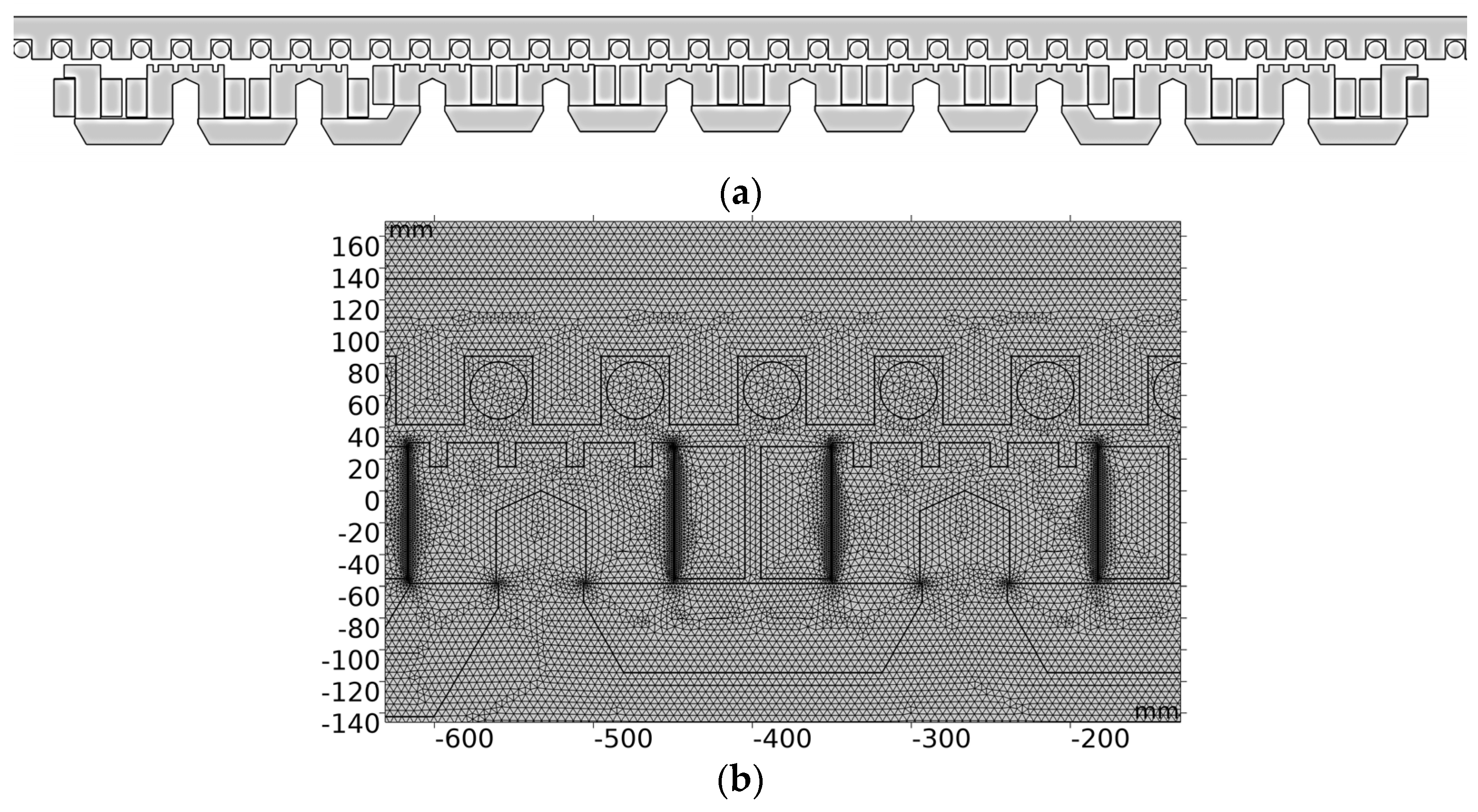
This article selected a single electromagnet module of the maglev and the corresponding length of stator for modeling and FEM simulation, as shown in
Figure 2a. In the model, the stator and mover cores were defined as non-linear magnetic steel materials, the stator and mover winding materials as copper, and the remaining part as air. The air domain was 10 times larger than the model dimensions in the x and y directions. The free triangular mesh was used for the mesh (
Figure 2b). The quality of the mesh was checked before FEM calculation. The number of elements was over 467,000, and there were 4–5 layers in the air gap region. A finer mesh would lead to a longer calculation time, but the results would have little difference.
The electromagnet module in this paper included 12 poles, of which 10 poles were standard poles and 2 poles were end poles which were shorter in width.
The magnetic field generated by a maglev system in the case of static suspension can be calculated according to the equivalent circuit method. The magnetomotive force (MMF) can be expressed as
If the iron core and air around the adjacent current cross-sections of two electromagnets are taken as the magnetic circuit, then according to Ohm’s law of the magnetic circuit:
where
F is the MMF,
N is the number of turns,
i is the current,
Rm is the magnetic resistance,
Φ is the magnetic flux,
li is the length of the ith magnetic circuit,
μi is the permeability of the ith magnetic circuit,
Ai is the area of the ith magnetic circuit, and
Bi is the magnetic flux density of the ith magnetic circuit.
For maglevs, traction force and suspension force are the two main mechanical performance parameters. According to Maxwell’s stress tensor, the relationship between the traction force and suspension force of a single electromagnet module of the EMS maglev and the air gap magnetic field can be expressed as
where
Fx and
Fy represent the traction force and suspension force, respectively [
2].
Lstack represents the thickness of the iron core;
L represents the length of the electromagnet module;
Bx and
By represent the
x-axis and
y-axis components of the air gap flux density.
According to the virtual displacement principle, the electromagnetic suspension force on the electromagnet is
where
Wm is the magnetic field energy,
B0 is the magnetic flux density in the air gap,
Ψ is the magnetic flux linkage,
A is the cross-section area of the electromagnet, and
μ0 is the vacuum permeability.
According to the flux continuity principle and Ampere’s circuit theorem,
In the equation,
μ1 denotes the magnetic permeability of the iron core,
N represents the number of turns in the electromagnets,
I indicates the current of the electromagnets,
l1 +
l2 denotes the magnetic circuit length within the iron core, and
z represents the air gap [
32].
The suspension force of a single electromagnet can be expressed as
where
A represents the pole area of an electromagnet [
33].
This equation calculates the total suspension force acting on an electromagnet module, assuming the magnetic permeability of the iron core is significantly greater than that of air. It can deliver results quickly and is widely used in EMS maglevs and their control systems, e.g., [
1,
33].
The EMS is not self-stabilizing and requires active control, both in static condition and in motion. Generally, the suspension control system controls the air gap at 8–10 mm. When the train is moving at high speed, there are obviously more and greater external disturbances, including track irregularity, aerodynamic forces, etc. Previous studies showed that air gap fluctuations increased with rising speed (Ref. [
33], replot in
Figure 3); other studies also showed a similar tendency [
34,
35].
Consequently, the air gap during high-speed operation is typically greater than that during low-speed operation. In order to prevent the train from hitting the track, the air gap will be larger at high speed than at low speed. From Equations (4) and (5), it can be seen that when the air gap increases, the current of the electromagnet coil needs to be increased to ensure that the suspension force remains unchanged. Due to the limitations of the electromagnet’s heat resistance of the turns’ insulation, the increase in electromagnet current is limited, so its lift-to-weight ratio needs to be increased as much as possible. In addition, as maglev transportation will inevitably develop towards a larger capacity in order to increase its market competitiveness, improving the lift-to-weight ratio is of great significance to the maglev transportation system. For a single electromagnet coil, the lift-to-weight ratio k is defined as
where
m is the mass of the electromagnet coil and
g is gravity [
36].
The air gap magnetic field constitutes the primary source of electromagnetic torque in electric motors. To investigate the spatial and temporal distribution of the air gap magnetic field, FFT analysis was employed. The
x-axis and
y-axis components of the air gap magnetic field can be expressed as
In this equation,
x is the distance from the beginning of the model,
i and
m refer to the spatial harmonic order of
Bx and
By, and
q and
λ refer to the temporal harmonic order of
Bx and
By.
N represents sampling points in the space domain, and
R represents sampling points in the time domain.
L is the length of sampling points. In this article,
N = 1536 and
R = 128.
L covers the length of electromagnet module and is 3096 mm [
2].
The calculations and analysis in this paper were based on the parameters of the maglev actually tested at Tongji University, with specific parameters shown in
Table 1.
The three-phase armature windings of the stator are supplied with three-phase symmetrical currents. Phases A, B, and C have respective phase angles of 0°, 120°, and 240°. The armature current is r.m.s. value in this article unless otherwise stated.
Maglevs operating at higher speeds require a larger air gap, which necessitates adjustments to the current electromagnetic parameters. This requires an analysis of the electromagnetic and mechanical properties.
3. Magnetic Field Under Static Suspension and Moving Conditions
Commercial FEM software can be employed to calculate the magnetic field distribution of the EMS maglev system under various operating conditions (different electromagnet current, armature current, air gap, etc.). The following first calculated the magnetic field distribution when the armature current was zero.
Figure 4 shows the FEM result of the
y-axis component of flux density in the static suspension condition of the EMS maglev in different electromagnet coil currents. The air gap was 10 mm in all cases. The peak of the
y-axis component of flux density in the air gap rose from 0.47 T to 1.02 T when the electromagnet coil current increased from 15 A to 35 A. When the current reached approximately 35 A, the increasing rate of the magnetic field decreased (
Figure 4d), at which point the iron core was nearing saturation. Since the pole pitches of the stator and mover are different and both the stator and mover cores are slotted, there are a large number of harmonics in the air gap magnetic field. Next, the magnetic field distribution when both the armature and the electromagnet coil were fed with current (double-fed) was calculated.
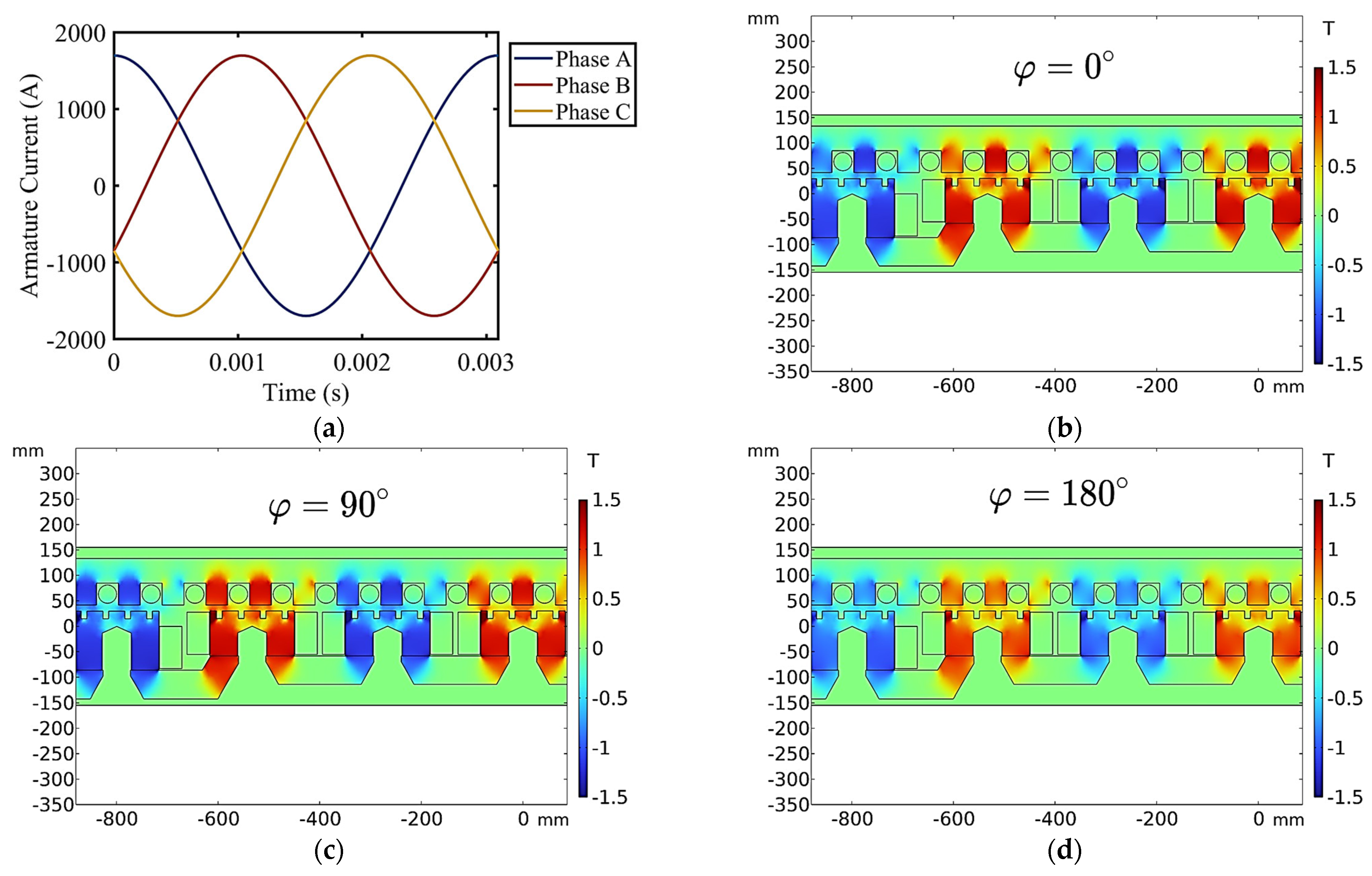
Figure 5a shows the three-phase armature currents when the maglev is operating at 600 km/h.
Figure 5b–d display the FEM result of the
y-axis component of flux density when the EMS maglev is doubly fed under different current phases. The air gap was 10 mm, the armature current was 1200 A, and the electromagnet coil current was 25 A. When the phase of the armature current changed, the magnetic field experienced a certain degree of variation. When the current phase was 0 degrees, the magnetic fields of the armature and the electromagnet coil were in phase, resulting in the peak magnetic flux density reaching its maximum; when the current phase was 180 degrees, the two magnetic fields were in opposite phase, leading to a reduction in magnetic flux density.
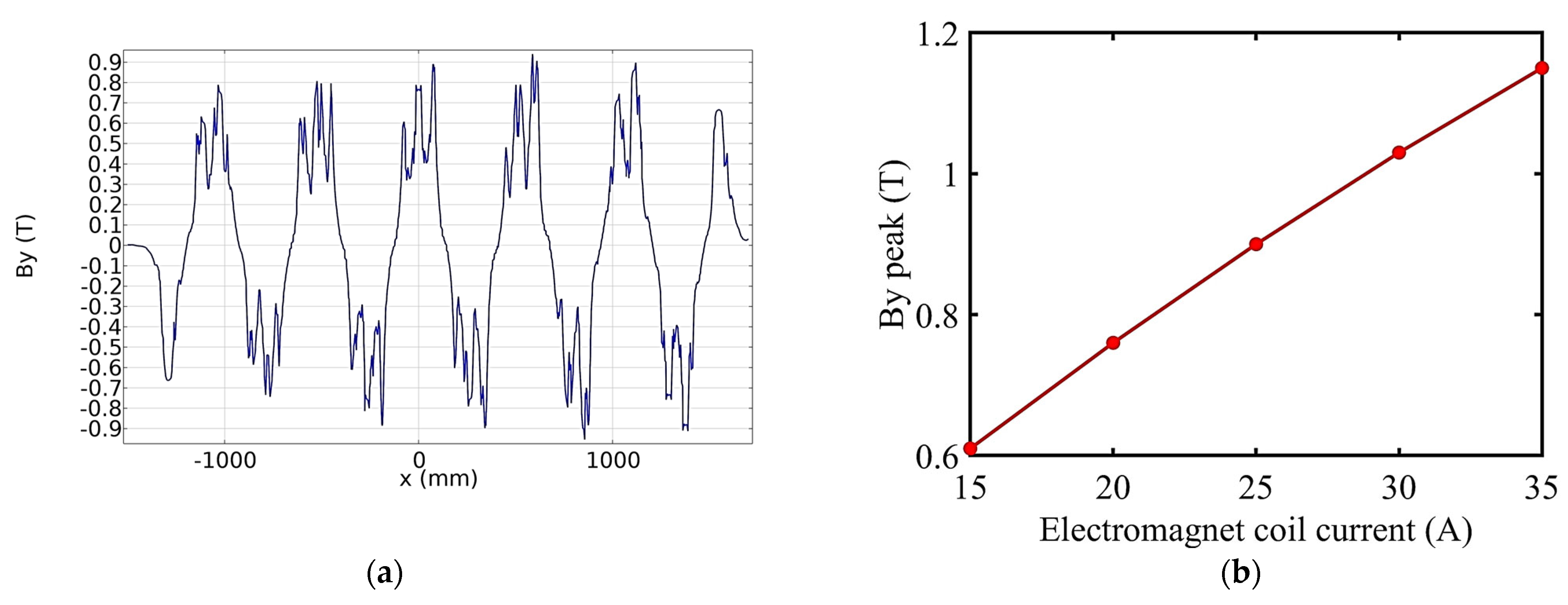
Figure 6a shows
By along the
x-axis of the EMS maglev when the air gap is 10 mm, the armature current is 1200 A, and the electromagnet coil current is 25 A. The peak of the
y-axis component of flux density in the air gap rose from 0.6 T to 1.15 T when the electromagnet coil current increased from 15 A to 35 A, as shown in
Figure 6b. Due to the fact that the magnetomotive force of the electromagnet coil is several times greater than that of the armature, the magnetic field in the air gap is mainly contributed by the electromagnet coil. The FEM result of
By matches well [
2], which reveals the accuracy of the FEM model.
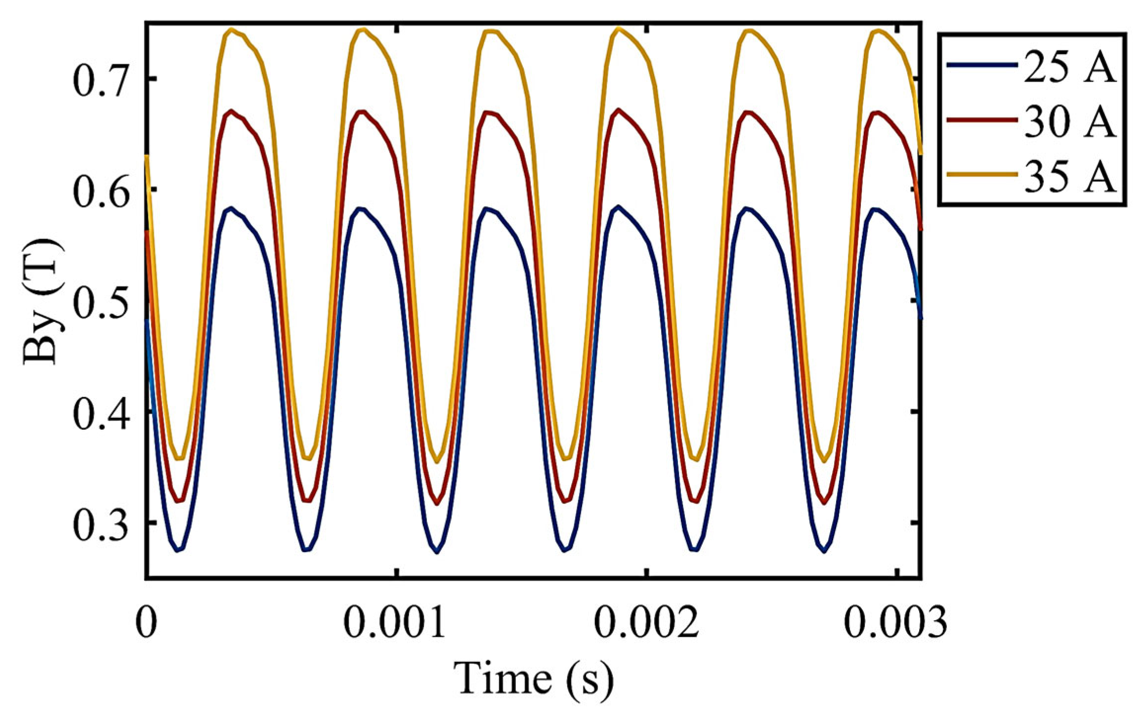
All the above are the distribution of the air gap magnetic field in space, and then the distribution of the air gap magnetic field in time was analyzed. A point at the air gap position in the center of the suspension magnetic pole was taken and analyzed in one period of the stator current frequency. The maglev was moving at 600 km/h.
It can be seen that due to the influence of the stator slots, the air gap flux density at the suspension magnetic pole fluctuates at approximately six times the stator current frequency. As shown in
Figure 7, if the electromagnet coil current was 25 A, the flux density fluctuated between 0.28 T and 0.58 T; if the electromagnet coil current was 35 A, the flux density fluctuated between 0.37 T and 0.74 T. These flux density harmonics can excite the linear generator to generate electricity. A more detailed harmonic analysis is provided later.
4. Relationship Between Mechanical Performance and Electromagnetic Parameters
Maglevs rely on synchronous linear motors for propulsion, with key performance metrics such as suspension force and traction force constituting core indicators of the maglev system. The influence of certain electromagnetic parameters on the suspension force and traction force is examined in this section. Firstly, the impact of the air gap on maglev performance is analyzed. For EMS-type maglev systems, the operational air gap typically ranges between 8 and 10 mm. FEM analysis revealed the relationship between suspension force and current within the electromagnet module when the electromagnet current was 25 A.
The theoretical equation obtained through the equivalent circuit method showed that the suspension force should be proportional to the square of the current, but when the current is large, the core may saturate, so the actual relationship is approximately linear. This approximate linear relationship brings convenience to control.
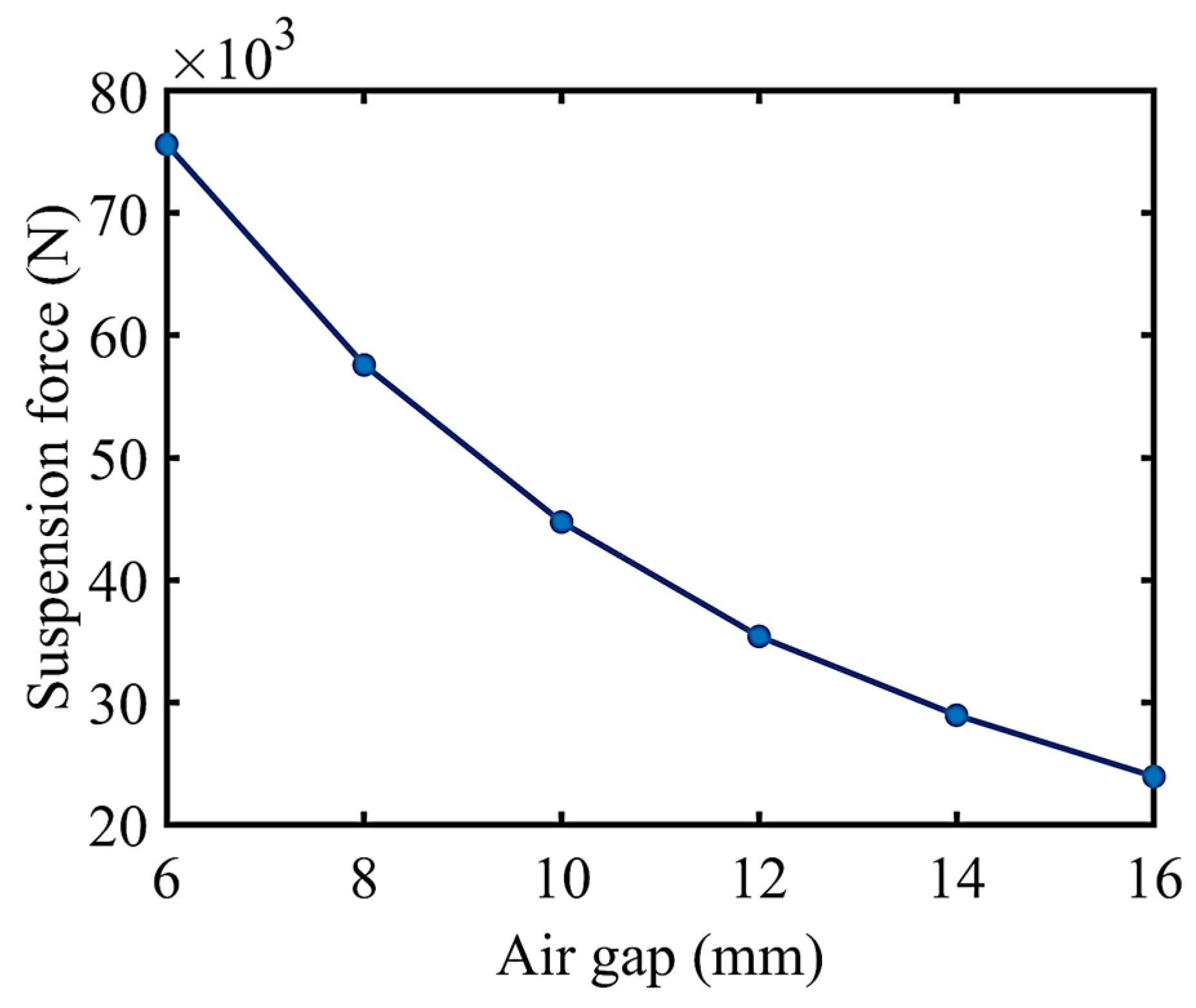
The relationship between the suspension force and air gap under the static suspension condition of a single electromagnet module (FEM) is displayed in
Figure 8. The FEM employed the Maxwell stress tensor to calculate electromagnetic forces (suspension and traction forces). Analytical methods such as Equation (6) can also compute the suspension force. However, this equation did not take into account the magnetic reluctance of the iron core and assumed a uniform magnetic field at a pole. As the air gap increased, the errors of the analytical method and the FEM gradually increased. The error was approximately 23.1% when the air gap was 8 mm. The analytical method can provide a quick estimation of the suspension force of a single pole, while the FEM can yield more accurate electromagnetic force calculations.
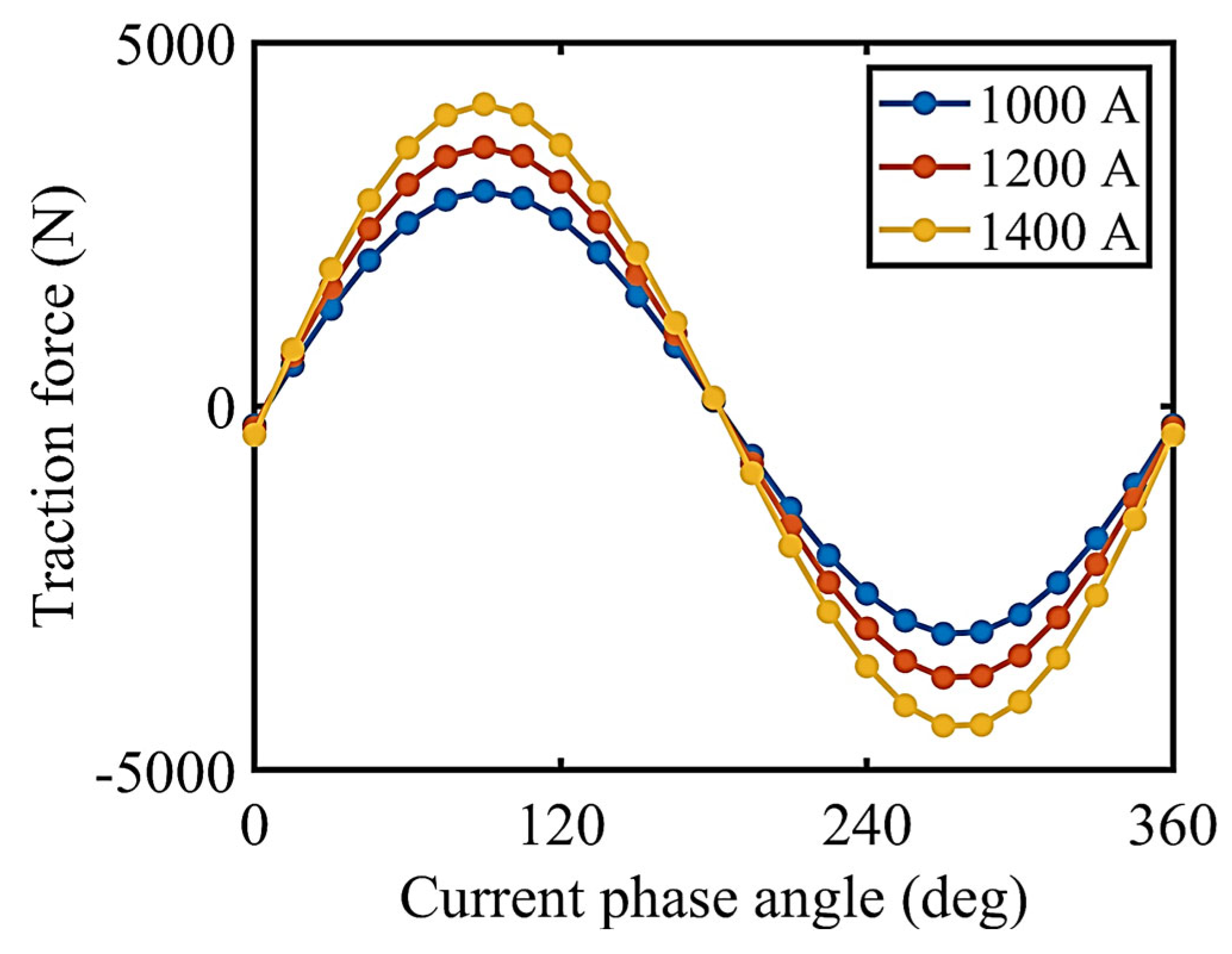
The stator of a linear motor generates a traveling magnetic field, which remains relatively stationary relative to the mover during synchronous operation. When the initial phase angle of the stator current changes, the spatial relationship between the stator and moving element magnetic fields also alters; consequently, this angle influences both the suspension force and traction force.
When the current phase angle was 90 degrees and the armature current was 1200 A (r.m.s.), the traction force reached a positive maximum of 3563 N for a single electromagnet module, and when the current phase angle was 270 degrees, the traction force reached a negative maximum −3727 N, as shown in
Figure 9. When the current phase angle reached 0 degrees, the traction force was approximately 0. The traction force is positively correlated to the armature current. Therefore, the traction force (brake force) can be controlled by adjusting the current phase angle and amplitude. The maglev was in stationary condition.
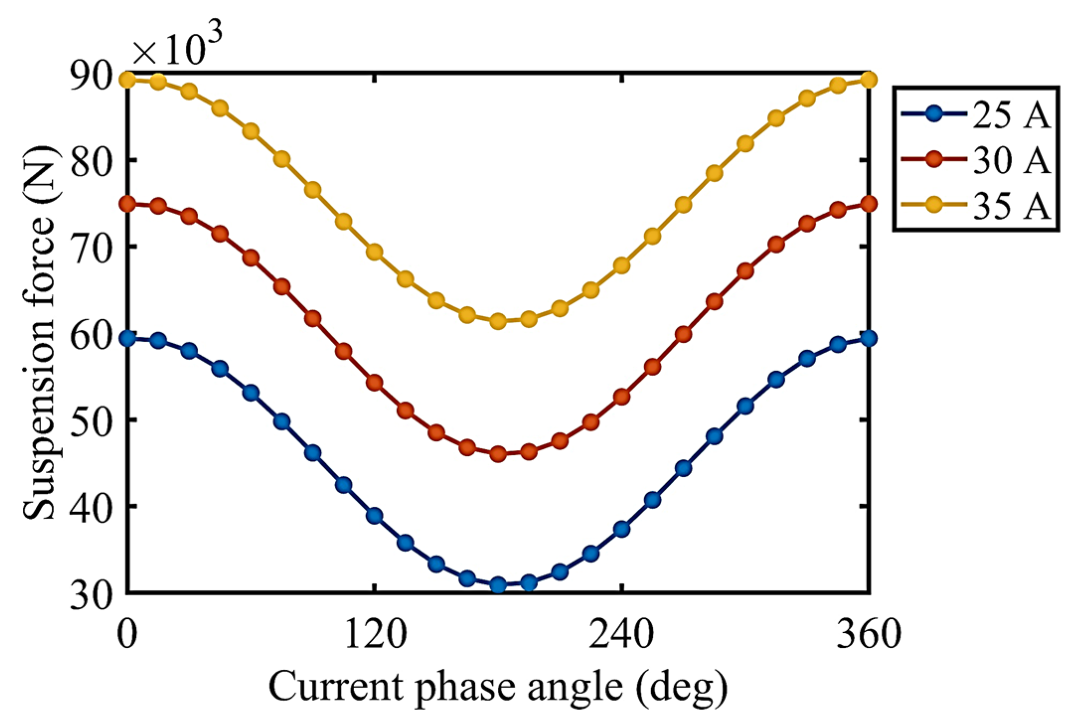
The current phase angle actually reflects the relationship between the magnetic fields of the armature and the electromagnet coils, as shown in
Figure 10. When the current phase angle was 0 and 180 degrees, the suspension force reached its maximum (59.4 kN) and minimum (31.0 kN), respectively, if the electromagnet coil current was 25 A. The suspension force increased to 61.4–89.2 kN if the electromagnet coil current increased to 35 A. The suspension force is positively correlated with electromagnet coil current. The maglev was in stationary condition.
Based on the above FEM results of the maglev system, in order to ensure operational safety, an increase of approximately 1 mm in the air gap is required for the maglev to operate at 600 km/h compared to 430 km/h. If the suspension force is to remain unchanged, the current of the suspension electromagnet coils must be increased to 27 A, resulting in a peak vertical magnetic field of approximately 0.86 T.
5. Harmonic Analysis of the Air Gap Magnetic Field
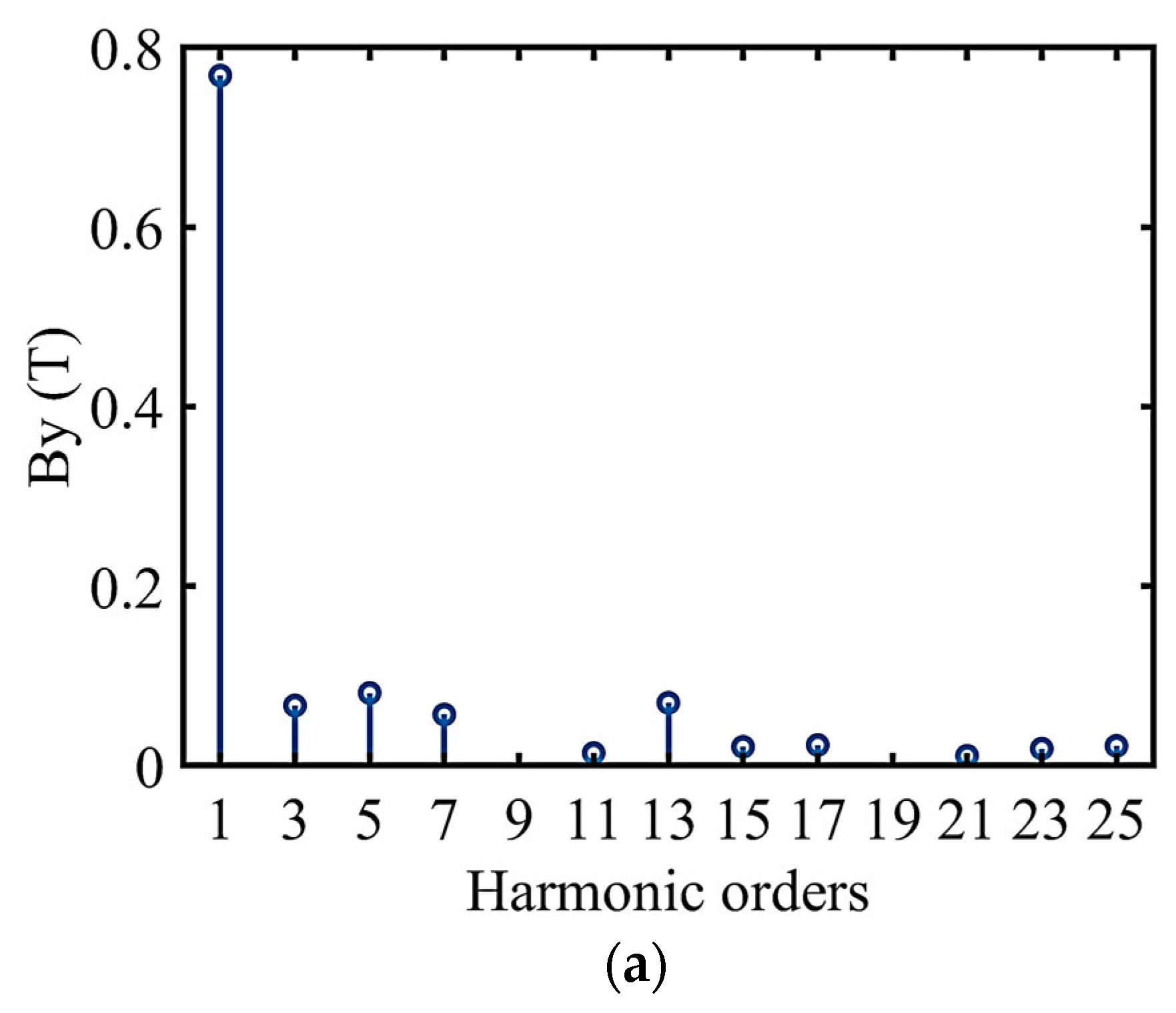
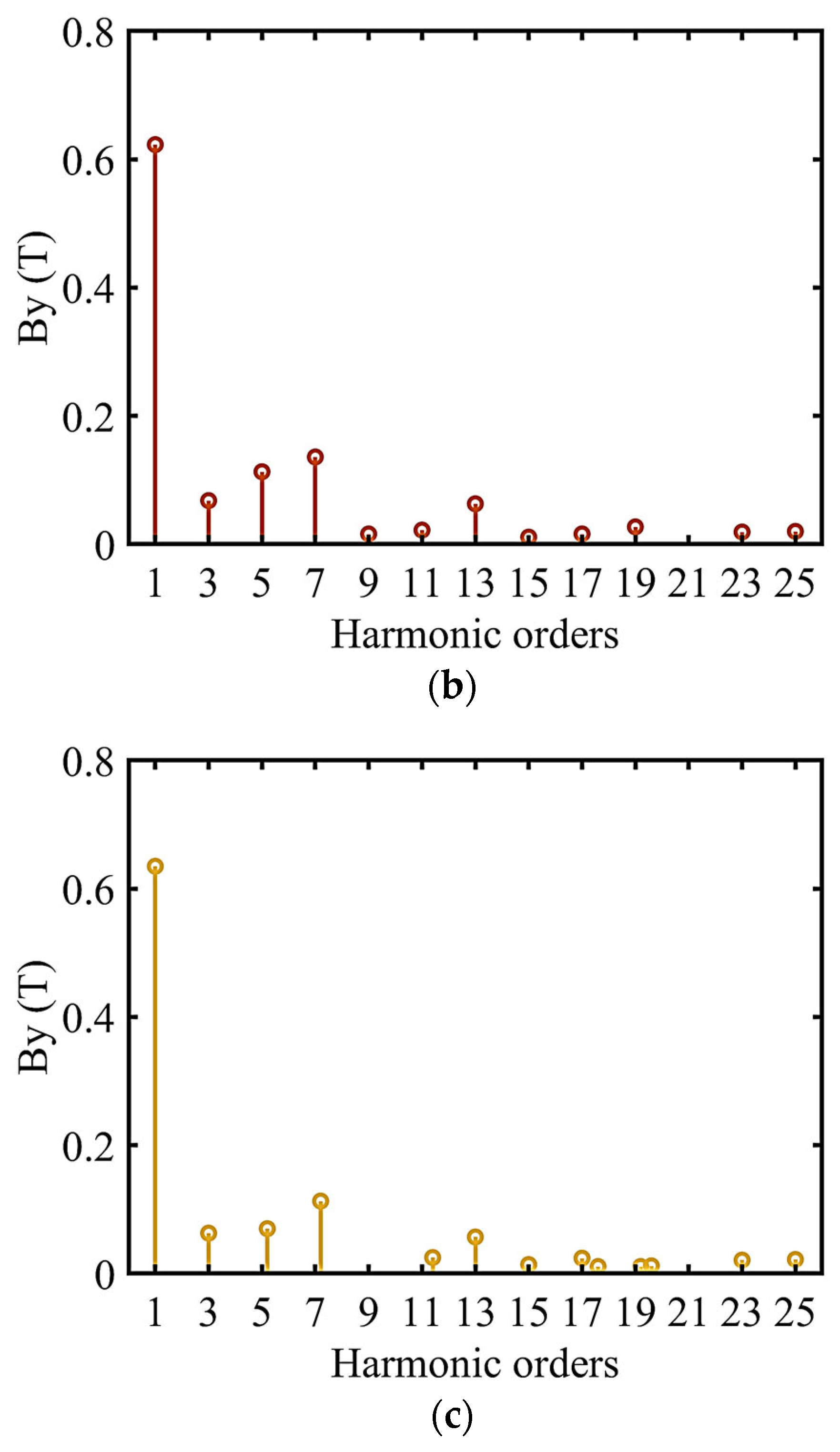
Both the stator and rotor of EMS maglevs have a slotted structure, and the pole pitch of the stator is not equal to that of the moving pole, making the harmonic of the air gap magnetic field relatively complex. To clarify the influence of stator slots on the harmonics of the air gap magnetic field, FFT was applied to the y-axis component of the air gap magnetic flux density for three different stator structures: (1) the stator is not slotted; (2) stator integer slots, two-pole six-slot configuration; (3) stator fractional slots, consistent with the actual system. The current of the electromagnet coil was 25 A, and the air gap was 10 mm.
From the FFT results (
Figure 11), it can be seen that the harmonic components generated in the three situations are mostly odd orders. The harmonic components of the stator with integer slots were slightly more than those without slots. The fifth and seventh harmonics were relatively high because the pole pitch of the moving stator was six times the slot pitch of the stator. When the stator was in fractional slots, fractional harmonics of 5.2 times and 7.2 times the fundamental frequency occurred. This was caused by the fact that the pole pitch of the moving stator is approximately 6.2 times the slot pitch of the stator.
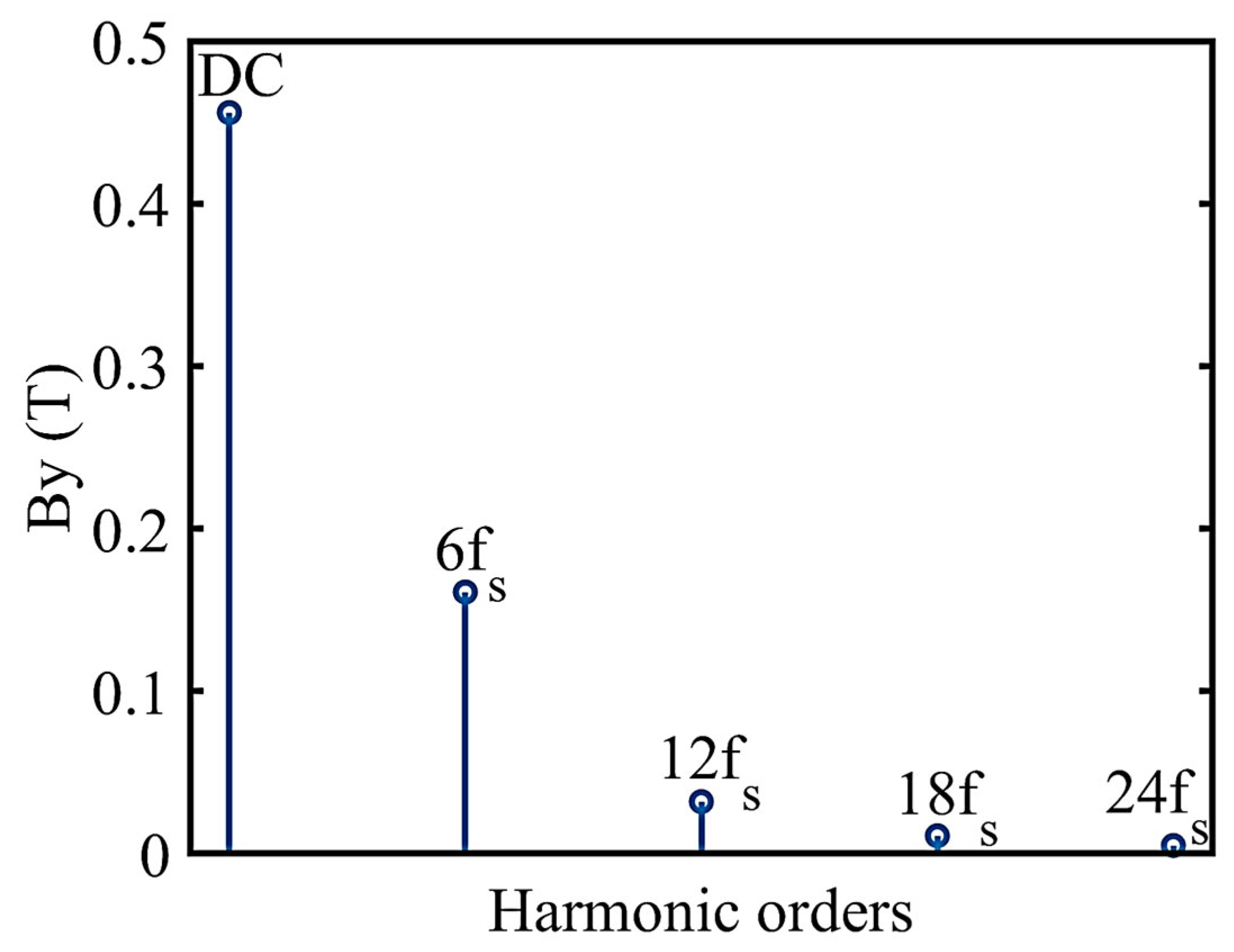
As can be seen from
Figure 12, the temporal harmonics of the air gap magnetic field comprise a direct current component and harmonic components at 6n times the stator frequency. The direct current component was approximately 0.46 T, while the sixth frequency harmonic component was approximately 0.16 T. This harmonic component arises from stator cogging and serves as the excitation magnetic field for the linear generator within the EMS maglev system.
It can be observed that the vertical magnetic field temporal harmonics of magnetic levitation, influenced by the cogging effect, are greater than the spatial harmonics from the harmonic analysis above. This will have a more significant impact on the electromagnetic and mechanical performance of the maglev system. In particular, the impact of magnetic field time harmonics on traction force fluctuations can lead to reduced passenger comfort and shorten the lifespan of certain components. Future efforts should focus on the temporal harmonics and optimize them accordingly.
