Abstract
To address the security and stability requirements of renewable energy clusters under extreme weather conditions, this study investigates the coordinated voltage support mechanisms between grid-following and grid-forming converters. This paper proposes an emergency control strategy suitable for such scenarios. First, a reactive power-voltage control architecture for new energy units is constructed to clarify the information interaction process. A mode-based coordinated strategy is designed: during steady-state voltage support, grid-following units adopt reactive power-voltage droop control for voltage regulation, while grid-forming units achieve autonomous support based on the virtual synchronous generator algorithm. During low-voltage ride-through, both types of units are controlled to output corresponding reactive power according to the depth of voltage drop until the voltage is restored. Hardware-in-the-loop simulation verification shows that under steady-state conditions, the strategy meets the voltage control accuracy requirements, and partial grid-forming transformation can reduce voltage overshoot and accelerate stabilization. During low-voltage ride-through, grid-forming transformation can reduce voltage fluctuations, shorten adjustment time, and mitigate reactive inrush current, effectively enhancing the voltage support capability of renewable energy plants.
1. Introduction
With the increasing integration proportion of renewable energy into power grids, the probability and frequency of extreme meteorological events such as typhoons, tornadoes, and severe storms have intensified due to global warming. This not only affects the reliability of power systems with high-proportion grid-connected renewable energy and transmission systems but also poses severe threats to the stable and safe operation of power grid equipment and the system as a whole [1,2].
To address the issue of power grid instability under extreme weather conditions, there are two main research approaches: one is to conduct research on new energy generation control technologies from the plant-side, enabling stable output of new energy generation power and equipping them with active power coordination control functions [3,4]; the other is to study new energy generation control strategies from the perspective of refined dispatching management on the grid side, so that large-scale grid-connected new energy can be controlled in accordance with the requirements of grid dispatching and operation modes [5]. However, restricted by various factors such as the capacity of energy storage devices, investment costs, and material levels, the development of emergency collaborative control technologies for new energy plant clusters under extreme weather conditions remains immature [6].
A renewable energy plant may contain various new energy units with different control strategies. According to the difference in synchronization mechanisms with the power grid, the converter control strategies of new energy units can be divided into grid-forming control and grid-following control [7,8]. Due to the differences in converter control strategies and electrical characteristics between grid-following and grid-forming new energy units, their parameters are mutually coupled and interacted, which makes their dynamic characteristics more complex and leads to certain coordination problems when both participate in voltage support.
In the field of microgrids, research on converter groups with two control modes has mostly focused on the steady-state operation control level. However, studies on the voltage support mechanisms and optimization strategies during their transient processes remain in a weak stage, making it difficult to meet the high requirements for transient voltage stability in new-type power systems.
Although research on the synchronization control strategies of grid-forming converters has been relatively mature, the sorting and summarization of transient control strategies for grid-forming converters under grid voltage drops are insufficient. For instance, how to better balance overcurrent limitation and active support capability during transients, as well as the specific performance and optimization directions of different control strategies in transient processes, still require further in-depth research.
The influencing factors of the voltage support capability of Virtual Synchronous Generator (VSG) control have not been clearly defined. Existing studies mostly focus on the improvement of control strategies, while insufficient consideration is given to the impact of control parameters. VSG control strategies that balance voltage support capability and short-circuit current limitation need to be thoroughly studied, especially methods to accurately adjust parameters to achieve the optimal balance between the two under different fault scenarios.
Grid-forming new energy units simulate the voltage source characteristics of synchronous generators through converters, actively regulating the amplitude and phase of the output voltage to directly support the voltage at the point of interconnection [9,10]. Ref. [11] designs a current synchronization control to achieve fault current limiting and synchronization stability of grid-forming converters, but it does not fully explore the adaptability of the control strategy to grid impedance changes in weak grid environments [12,13]. Ref. [14] analyzes the transient stability of hybrid power systems dominated by different types of grid-forming devices, yet it fails to conduct an in-depth analysis of the impact of interactions between different grid-forming devices on system transient stability under extreme weather conditions [15,16]. Ref. [17] designs the contribution ratio of grid-forming and grid-following converters to frequency stability but does not fully discuss the dynamic adjustment mechanism of the contribution ratio between the two types of converters in scenarios with high-proportion new energy fluctuations. Ref. [18] realizes power sharing and voltage restoration in microgrids dominated by grid-forming converters; however, it does not fully investigate the response speed and stability adaptability of the control strategy when new energy output changes abruptly. Ref. [19] analyzes the key design points of current-limiting control for grid-forming capability of voltage source converters under large grid disturbances, but lacks an exploration of the interactive coupling impact of current-limiting control when multiple VSCs operate in parallel. Ref. [20] establishes a small-signal model of islanded microgrids containing grid-forming converters and synchronous machines, analyzes the small-signal stability, but lacks applicability verification. Ref. [21] studies the grid supporting effect of grid-forming energy storage systems under distribution network faults, yet does not fully explore the adaptive adjustment mechanism of the supporting strategy of grid-forming energy storage systems when the impedance characteristics of distribution networks change dynamically due to high-proportion new energy integration. Ref. [22] proposes a steady-state convex model for the bidirectional DC-DC converter (BDC), which transforms the originally complex non-convex problem into a convex optimization problem, significantly reducing the computational complexity. It mainly focuses on the steady-state model and steady-state economic dispatch, with relatively few analyses on the operating characteristics of the AC-DC hybrid microgrid under dynamic processes. However, few studies have elaborated on the coordination issues between grid-following and grid-forming new energy units when they jointly participate in system voltage support.
To address the increased voltage and frequency incidents as well as insufficient stability of renewable energy plants under extreme weather conditions, give full play to the regulation potential of grid-forming characteristic units, and achieve complementary advantages, this study focuses on developing a coordinated voltage support emergency control strategy suitable for renewable energy plant under extreme weather. First, a reactive power-voltage control architecture for new energy units is constructed, and the information interaction process of reactive power-voltage control for new energy units is clarified. Second, a coordinated voltage support control strategy for renewable energy plants containing grid-following and grid-forming units is designed. The control modes are divided into steady-state voltage support and low-voltage ride-through (LVRT) according to the degree of voltage drop. Taking advantage of the flexible response characteristics of grid-following new energy units, reactive power-voltage droop control is incorporated to achieve steady-state voltage regulation; for grid-forming new energy units, steady-state voltage autonomous support is realized based on the virtual synchronous generator control algorithm. During the LVRT period, according to the depth of voltage drop, grid-following and grid-forming new energy units are controlled to output corresponding reactive power until the fault voltage returns to stability. Finally, a voltage support simulation system for renewable energy plants is built to verify the effectiveness of the proposed coordinated voltage support control strategy.
2. Reactive Power and Voltage Control Architecture for Renewable Energy Plant
2.1. Automatic Voltage Control Architecture of Renewable Energy Plant
The reactive power and voltage control architecture of the renewable energy plant, as shown in Figure 1, generally consists of the dispatching automatic voltage control (AVC) master station, dispatching data network channel, and renewable energy plant computer monitoring system.
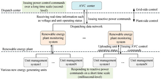
Figure 1.
Reactive power control architecture diagram of new energy units.
The AVC center is the core of the entire control system. It can periodically acquire relevant information of new energy power stations, including actual active power, reactive power, short-term power prediction, etc. The dispatching data network channel realizes bidirectional data interaction between the AVC master station and the computer monitoring system of new energy power stations, ensuring the reliable transmission of control commands and operating status data.
This architecture is compatible with both steady-state voltage support and low-voltage ride-through (LVRT) control modes: in the steady state, the system ensures that units regulate voltage according to reactive power-voltage droop control and autonomously support voltage based on the virtual synchronous generator algorithm through command allocation; when LVRT is triggered, it can quickly transmit voltage drop signals, driving the two types of units to output corresponding reactive power according to the drop depth, forming a closed-loop control of “decision-making—execution—feedback”, which provides structural support for the voltage stability of new energy power stations under extreme weather conditions.
2.2. Automatic Voltage Control of Renewable Energy Plant
With reference to the AVC technical standards of the state grid corporation of China, the AVC center shall coordinate the generating units within the renewable energy plant, take into account the adjustable reactive power range of new energy units, issue voltage and reactive power regulation commands to the new energy units within this range, and automatically control the new energy units to participate in voltage support.
The control modes of renewable energy plants are divided into two parts: steady-state voltage support mode and LVRT mode. During steady-state voltage support, the point of interconnection voltage should be adjusted to the voltage target value, which is issued by the dispatching master station or preset. Based on the received voltage target value and the current voltage, the reactive power should be reasonably allocated by comprehensively considering the operating status and output of each new energy unit, with the voltage regulation time and control accuracy meeting the operation requirements. When the point of interconnection voltage drops to a certain threshold, the LVRT mode is triggered, and the new energy units need to continuously output reactive current for support until the voltage returns to a stable value.
The AVC strategy for renewable energy plants shall satisfy the following constraint conditions:
(1) The point of interconnection bus voltage limit constraint;
(2) Reactive power regulation capability constraint of new energy units;
(3) Regulation rate constraint of new energy units.
When the AVC master station takes the grid-connected point bus voltage as the control object, the requirements for voltage control accuracy are as follows according to the voltage level of the power plant’s grid-connected bus:
(1) For bus with voltage level of 35 kV and below, the bus voltage control accuracy requirements are shown in Equation (1):
where Vreal is the bus voltage measurement; Vset is the bus voltage target value.
(2) For buses with a voltage level of 66 kV~220 kV, the requirements for bus voltage control accuracy are given in Equation (2):
where Vreal is the bus voltage measurement; Vset is the bus voltage target value.
(3) For buses with a voltage level of 330 kV~500 kV, the requirements for bus voltage control accuracy are given in Equation (3):
where Vreal is the bus voltage measurement; Vset is the bus voltage target value.
The time ratio of new energy AVC automatic control is defined in Equation (4):
where R is the AVC operation rate of renewable energy plants; Tclose is the investment AVC closed-loop running time; Top is the station operating time.
The AVC operation rate of renewable energy plants should not be less than 98%.
3. Cooperative Voltage Support Control Strategy for Renewable Energy Plants
3.1. Two Voltage Support Control Modes
Figure 2 is a schematic diagram of the voltage support range of new energy units participating in the power grid. Under the normal operation of the system, the reactive power in the system should be dynamically balanced, and the voltage is within the steady-state interval [Ulowmax, Uupmax], in this voltage state, the new energy unit will adopt appropriate control strategies to participate in the steady-state voltage support according to the operating state. When the voltage drops to the lower voltage limit Ulowmax, the LVRT is considered according to the GB/T19964-2012 power grid standard.

Figure 2.
Schematic diagram of support range for new energy units.
The voltage drop range [0, Ulowmax] is divided into three ranges as shown in Figure 3 according to the depth of voltage drop, and each drop depth needs to provide different degrees of reactive power support.

Figure 3.
Voltage drop degree diagram.
The core principles are as follows: When the voltage drop is in a deep drop, new energy units shall respond rapidly and fully support reactive power; when the voltage drop is in a moderate drop, each new energy unit shall output reactive power in proportion while ensuring equipment safety; when the voltage drop is in a slight drop, priority shall be given to stabilizing the power grid and gradually restoring the voltage.
When the point of interconnection voltage drops in [Ulowmax, Uupmax], the reactive power-voltage drop control unit participates in the steady-state voltage support of the grid-following new energy unit, and the reactive power-voltage drop characteristics are shown in Equation (5).
where Qset is the reactive power setting value of the grid-following new energy unit, the output of inductive reactive power is defined as a positive value, while the absorption of inductive reactive power is defined as a negative value, with the unit of kVar; Kdroop is the voltage drop coefficient; Vref is the reference voltage amplitude, with the unit of kV; Vmeans is the amplitude of the measured voltage, with the unit of kV.
The grid-following new energy unit adopts the voltage independent support shown in Equation (6):
where E0 is the rated voltage; Qref is the reactive power setpoint of the grid-following new energy unit; Q is the measured value of reactive power output by each renewable energy unit; KQ is the reactive drop coefficient; KU is the voltage drop coefficient; Uref is the voltage setpoint; U is the measured value of the point of interconnection voltage; E is the reference value of the converter voltage output.
If the voltage drops to the range of [0.2UN, 0.9UN], the steady-state voltage regulation shall be stopped and the LVRT mode shall be triggered. In accordance with the grid standard GB/T 19964-2012 [23], the requirements for reactive current output are given in Equation (7):
where Kv is the proportional coefficient required by the power grid (Chinese standards usually take 1.05); Vp.u. is the standard value of the actual voltage; Irated is the maximum continuous output current of the converter.
If the voltage drops to 0.2UN, it is in a deep drop state, and the reactive current requirements are shown in Equation (8), at this time, the active power output is suspended, and the reactive power support grid voltage is fully output.
The adjusted voltage shall comply with grid specifications, with a 5% fluctuation threshold, i.e.:
In addition, a power output limitation module is incorporated, as shown in Equation (10):
where SN is apparent power; PN is the rated active power.
3.2. Cooperative Voltage Support Control Strategy for Grid-Following and Grid-Forming New Energy Units
Figure 4 shows the control block diagram for coordinated voltage support of a renewable energy plant containing grid-following and grid-forming units. Following the process of “real-time information input—hierarchical control decision-making—unit execution response”, the top-level coordinated voltage regulation control strategy receives the measured values of grid voltage and generates reactive power commands for issuance; grid-forming units adopt dual closed-loop control to simulate the voltage source characteristics of synchronous generators and provide basic voltage support; grid-following units integrate primary frequency modulation and voltage control to supplement dynamic reactive power regulation.
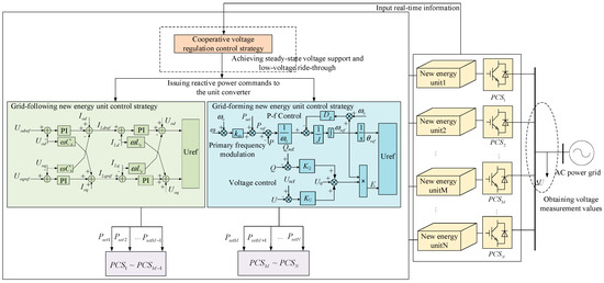
Figure 4.
Coordinated voltage support control block diagram of new energy power station.
This reactive power control loop integrates the dual control logic of proportional-integral regulation for reactive power deviation and voltage feedback, presenting significant advantages. Compared with the simple reactive power-voltage droop control, it can achieve static-error-free and precise regulation of reactive power by means of the PI controller, thereby improving the reactive power allocation accuracy when multiple virtual synchronous generators operate in parallel. In contrast to the reactive power loop relying solely on PI, it further enhances the rapid response and stability capability to system voltage through the voltage feedback link. This enables more efficient balancing of reactive power and voltage under dynamic operating conditions, featuring both high precision and strong adaptability, which is suitable for the strict regulation requirements of complex power grids for reactive power and voltage.
Figure 5 presents the control flow chart for coordinated voltage support of a renewable energy plant comprising grid-following and grid-forming units, with the specific process as follows:
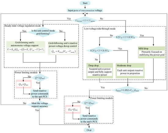
Figure 5.
Flowchart of coordinated voltage support control for new energy power station containing grid-following and grid-forming units.
(1) First, enter the point of interconnection voltage value detected in real time to detect the degree of voltage drop;
(2) Determine whether the voltage drop is within the steady-state range [Ulowmax, Uupmax], and if it is in the range, the new energy unit enters the steady-state voltage support mode. For grid-following new energy units, they participate in steady-state voltage support according to Equation (5), and for grid-following new energy units, voltage independent support is carried out according to Equation (6).
(3) If the new energy unit is in the steady-state voltage support working mode, the new energy unit stops the voltage support and then detects whether the adjusted voltage meets the voltage control accuracy described in Section 2.2. If the condition is satisfied, the current control cycle is terminated; otherwise, the extent of the voltage drop is re-evaluated, and the next iteration of voltage support is initiated.
(4) If the voltage drops outside the steady-state range, the new energy unit triggers the LVRT mode. According to the degree of voltage drop, it is divided into three working conditions: light drop, moderate drop and deep drop, and each working condition outputs corresponding reactive power to the new energy unit of the network and grid construction.
(5) If the new energy unit is in the low voltage traversal working mode, check whether the output reactive current of the new energy unit meets Equation (7), and if it meets the requirements, judge whether the reactive power of the new energy unit exceeds the limit, otherwise it will re-enter the next cycle;
(6) Detect whether the reactive power output exceeds the limit, if it exceeds the limit, output the maximum reactive power support voltage, if it does not exceed the limit, the AVC controller will finally issue the generated reactive power command to the grid type and grid type new energy unit converter.
4. Simulation Verification
The impact of extreme weather events on power systems has become increasingly prominent. As one of the core indicators for the safe operation of power systems, voltage stability is highly susceptible to deterioration under the influence of extreme weather. Different types of extreme weather can cause various forms of disturbances to grid voltage through multiple pathways, such as damaging power facilities, altering load characteristics, and affecting equipment output, thereby posing severe challenges to the stable operation of power systems. To clearly illustrate the specific impact of extreme weather on grid voltage under different scenarios, the core impacts of various extreme weather types on voltage and their quantitative indicators are detailed in the following table (see Table 1).

Table 1.
Impact of different types of extreme weather on power grid voltage.
To verify the effectiveness of the coordinated voltage support control strategy for renewable energy plants proposed in this paper against voltage drops, a simulation system for voltage support of renewable energy plants is built, whose topological structure is shown in Figure 6. The system consists of five new energy units and their respective converters. The new energy units are connected to the large AC power grid through step-up transformers after passing through filter circuits.
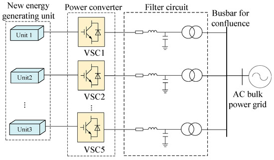
Figure 6.
Topology diagram of the voltage support simulation system of renewable energy plant.
RT-LAB (OP5600) is used for real-time simulation with given parameters. The platform mainly consists of an RT-LAB (OP5600) real-time simulator, a host computer, a wave recorder and an actual controller, as shown in Figure 7. The grid-connected system model built in Simulink is transferred from the host computer to RT-LAB. The proposed coordinated voltage support emergency control strategy is deployed in the actual PV inverter controller, whose PWM pulses are sent to the pulse input port of RT-LAB. After data processing, the experimental waveforms are recorded by the wave recorder.
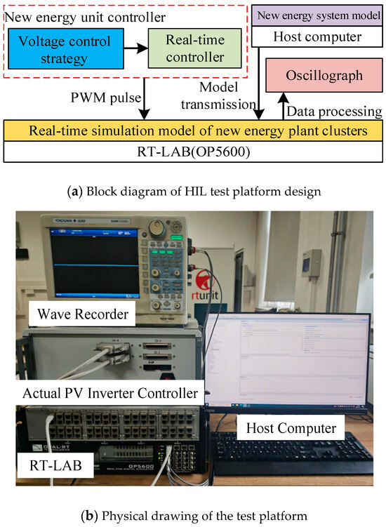
Figure 7.
RT-LAB real-time simulation platform.
To more intuitively verify the effect of the proposed control strategy, the data from the recorder is exported, and different experimental waveforms are plotted in the same coordinate system using plotting software. The main parameters of the simulation system are listed in Table 2.

Table 2.
Main parameters of the system.
4.1. Steady-State Voltage Support Simulation
(1) Normal operating conditions of new energy units
A voltage drop of 0.05 p.u. is set at 2 s, and the voltage recovers at 3 s. All five new energy units adopt grid-following control. The comparison of voltage waveforms before and after the proposed coordinated voltage support control strategy is put into operation is shown in Figure 8.
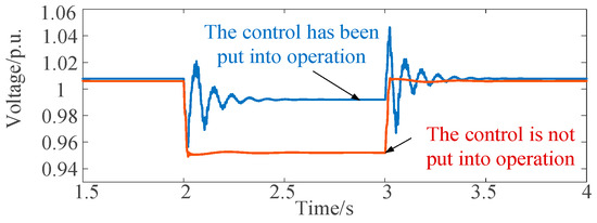
Figure 8.
Comparison diagram of voltage waveforms when voltage drops by 0.05 p.u. (All new energy units are grid-following type).
As can be seen from Figure 8, after the proposed coordinated voltage support control strategy is put into operation, the voltage rebounds after approximately 0.2 s, and the raised voltage is about 0.997 p.u. The bus control accuracy is 0.105 kV, which meets the 35 kV voltage regulation accuracy requirement. The voltage starts to recover at 3 s with an obvious overshoot, reaching a maximum of 1.045 p.u., and stabilizes after about 0.5 s.
Figure 9 shows the reactive power output diagram of five grid-following new energy units when participating in steady-state voltage support. It can be seen that all five new energy units can operate stably during the period of 2~3 s. Each new energy unit continuously and stably outputs reactive power to support the grid voltage drop, and the reactive power is less than the maximum limit. When the voltage recovers at 3 s, the units stabilize and stop operating.
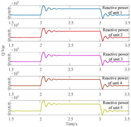
Figure 9.
The reactive power output of the new energy unit when the voltage drops by 0.05 p.u.
(2) Grid-forming transformation of some new energy units
One of the new energy unit converters is configured with grid-forming control, and the proposed coordinated voltage support control strategy is implemented. With other operating conditions remaining unchanged, the comparison of voltage waveforms is shown in Figure 10.
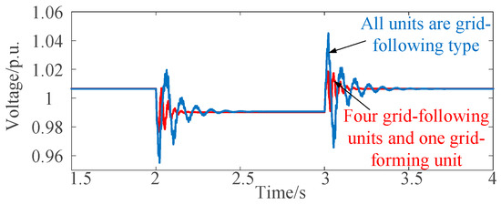
Figure 10.
Comparison diagram of voltage waveforms for new energy units adopting different control strategies.
As can be seen from Figure 10, when one of the new energy units is adopted with grid-forming control, the voltage drops at 2 s and stabilizes after approximately 0.2 s. The voltage starts to recover at 3 s and stabilizes after about 0.2 s of adjustment, with the maximum overshoot voltage reaching 1.09 p.u. Compared with the scenario where all new energy units adopt the grid-following mode, during voltage drop, the maximum voltage overshoot decreases from 3.9% to 1.5%, and the adjustment time reduces from 0.5 s to 0.2 s; during voltage recovery: the maximum voltage overshoot decreases more significantly from 4.0% to 1.5%, and the adjustment time reduces from 0.5 s to 0.2 s. Therefore, the grid-forming transformation of some new energy units can effectively reduce the overshoot during voltage drop and recovery and enable the voltage to reach a stable value more quickly.
(3) Power over-limit conditions
A voltage drop of 0.1 p.u. is set at 2 s, and the voltage recovers at 3 s. All five new energy units adopt grid-following control, and the simulation results are shown in Figure 11 and Figure 12.
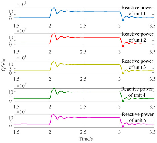
Figure 11.
Reactive power output of the new energy unit when the voltage drops by 0.1 p.u.
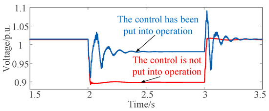
Figure 12.
Comparison diagram of voltage waveforms when voltage drops by 0.1 p.u. (All new energy units are grid-following type).
From the simulation results, it can be seen that after the proposed control strategy is implemented, compared with the scenario before its implementation, the voltage is raised to 0.98 p.u., and the bus control accuracy is 0.7 kV, which does not meet the specified voltage regulation accuracy for 35 kV. This is because all new energy units are in a state of power over-limit. Even if all five new energy units support the voltage drop with their maximum reactive power, it is insufficient to restore the voltage to the specified value. In such cases, better voltage support effects can be achieved by increasing the number of devices or upgrading the unit capacity.
4.2. Low-Voltage Ride-Through Simulation
Taking the operating condition where the voltage drops to 0.8 p.u. as an example, when the voltage drops to 0.8 p.u., the Chinese national standard (GB/T 19963-2021 [24]) stipulates that the minimum duration required for LVRT is generally 150 ms to 1 s. A voltage drop to 0.8 p.u. is set at 2 s, with the voltage recovering at 3 s, so the duration of LVRT is 1 s.
(1) Normal operating conditions of new energy units
All five new energy units adopt grid-following control, and the simulation results are as follows:
As can be seen from Figure 13, during the period when the voltage drops to 0.8 p.u., the new energy units can operate stably, and a single grid-following new energy unit outputs approximately 0.5 Mvar of reactive power to assist in grid voltage recovery. The new energy units respond rapidly to the voltage drop at 2 s, with a response time of about 8 ms. During the voltage drop, the new energy units continuously provide 6.8 A of reactive current (capacitive), which meets the reactive current requirement during the fault. However, there are large reactive inrush currents at the moment of voltage drop and during voltage recovery. Compared with grid-following units, during voltage recovery, the difference between the reactive surge current and the steady-state current output by grid-forming units is reduced from 4.29 A to 3.26 A.
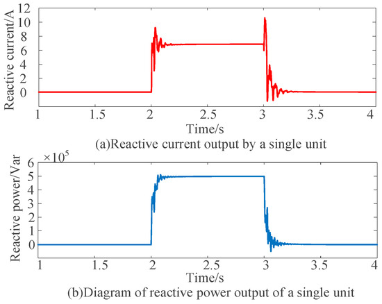
Figure 13.
Voltage drop of 0.8 p.u. reactive current and reactive power of grid-following new energy units.
As can be seen from Figure 14, after the proposed coordinated voltage support control strategy is implemented, the voltage reaches 0.84 p.u., which exhibits a good voltage support effect during the LVRT period.
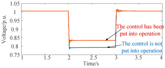
Figure 14.
Voltage waveform comparison of the proposed control strategy activation at a 0.8 p.u. voltage drop.
(2) Grid-forming transformation of some new energy units
One of the new energy units is adopted with grid-forming control, while other operating conditions remain unchanged. The reactive power outputs of the five new energy units are shown in Figure 15:
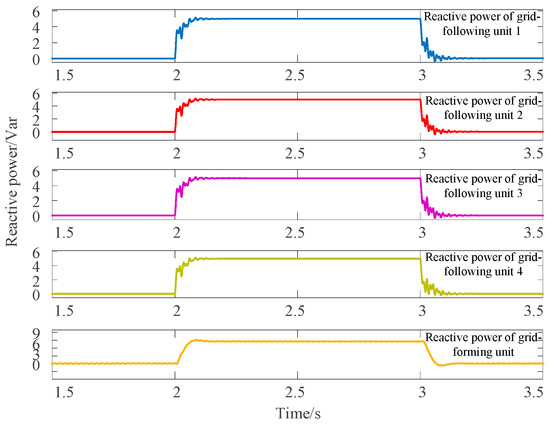
Figure 15.
The reactive power output of each new energy unit when the voltage drops by 0.8 p.u.
As can be seen from Figure 15, during the LVRT period from 2 s to 3 s, both the grid-following new energy units and the grid-forming new energy unit can continuously provide reactive power to support the voltage drop. Each of the four grid-following new energy units’ outputs approximately 0.5 Mvar of reactive power, while the grid-forming new energy unit provides 0.8 Mvar of reactive power.
As can be seen from Figure 16, both the grid-following and grid-forming new energy units can respond rapidly when the voltage drops at 2 s. During the voltage drop, the grid-following new energy units continuously provide 6.8 A of reactive current (capacitive), which meets the reactive current requirement during the fault. However, there are large reactive inrush currents at the moment of voltage drop and during voltage recovery. The grid-forming new energy unit continuously provides 7.9 A of reactive current (capacitive) during the voltage drop, which also meets the reactive current requirement during the fault. Compared with the grid-following new energy units, the amplitude of inrush current at the moment of voltage drop and recovery is smaller for the grid-forming new energy unit.
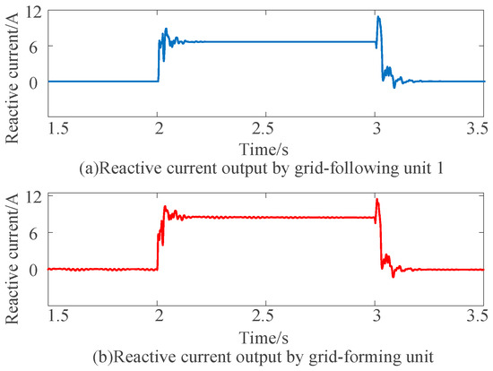
Figure 16.
When the voltage drops by 0.8 p.u., the new energy unit outputs reactive current to the network and the grid.
Figure 17 shows the comparison diagram of voltage waveforms before and after the grid-forming new energy unit is put into operation. It can be seen from the simulation results that when one of the new energy units is transformed into a grid-forming type, the voltage fluctuation degree and adjustment time can be reduced, and the voltage can reach a stable value more quickly. Compared with the scenario without grid-forming units, after integrating grid-forming units: the fluctuation amplitude of voltage at the moment of voltage drop is reduced from approximately ±0.03 p.u. to ±0.015 p.u., achieving a significant fluctuation suppression effect; the adjustment time during the voltage recovery stage is shortened from the original 0.35 s to 0.18 s, with the stabilization speed improved by approximately 48.6%.
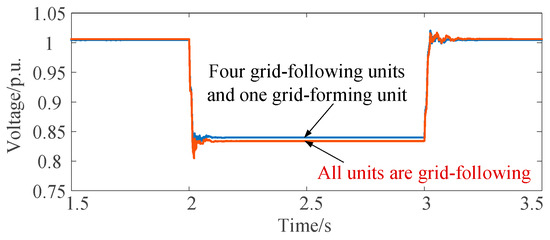
Figure 17.
Voltage waveform comparison with and without grid-forming renewable energy generators during a 0.8 p.u. voltage drop.
4.3. Asymmetric Fault Voltage Support Simulation
(1) Asymmetric Faults in New Energy Units
An asymmetric single-phase-to-ground fault is set to occur at 2 s, resulting in a voltage drop of 0.955 p.u. The voltage is restored at 3 s. All five new energy units adopt grid-following control. The comparison of voltage waveforms before and after the implementation of the proposed coordinated voltage support control strategy is shown in Figure 18.
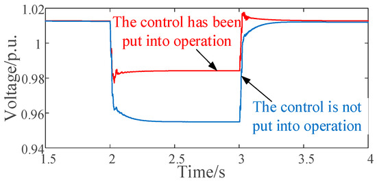
Figure 18.
Comparison of Voltage Waveforms Before and After Implementing the Proposed Control Strategy for Asymmetric Single-Phase-to-Ground Fault with a Voltage Drop of 0.92 p.u.
It can be seen from the simulation results that the proposed strategy still has excellent voltage support capability under asymmetric faults.
(2) Partial units undergo grid-forming transformation
An asymmetric single-phase-to-ground fault is set to occur at 2 s, leading to a voltage drop of 0.03 p.u., and the voltage is restored at 3 s. When the first grid-following power station triggers the reactive power limit, the AVC redistributes the reactive power output among the various units, as shown in Figure 19.
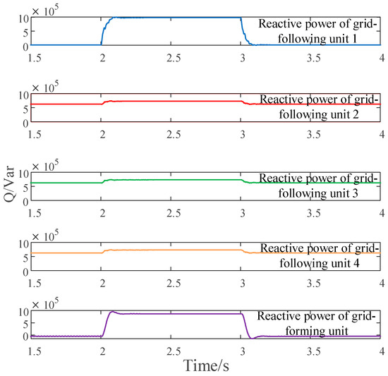
Figure 19.
Reactive power output of each new energy unit when a voltage drop of 0.97 p.u. occurs due to an asymmetric single-phase-to-ground fault.
It can be seen from the simulation results that when the first grid-following unit triggers the reactive power limit, the remaining grid-following units output reactive power on average, while the grid-forming units undertake the task of outputting more reactive power.
5. Conclusions
In view of the application scenarios where grid-following and grid-forming new energy units in renewable energy plant participate in voltage support, this paper proposes a coordinated voltage support control strategy for renewable energy plant containing both grid-following and grid-forming units. Through analysis and experiments, the following conclusions are drawn:
(1) Under the steady-state voltage support condition, when all new energy units adopt grid-following control, the proposed control strategy can provide a good voltage support effect. The adjusted bus voltage control accuracy is 0.105 kV, which meets the control specifications. After adopting grid-forming control for some new energy units, the overshoot during voltage drop and recovery can be effectively reduced, and the voltage can reach a stable value more quickly.
(2) Under the LVRT condition, when all new energy units adopt grid-following control, the voltage support effect is good. During the voltage drop, the new energy units continuously provide 6.8 A of reactive current, which meets the reactive current requirement during the fault. However, there are large reactive inrush currents at the moment of voltage drop and during voltage recovery. After adopting grid-forming control for some new energy units, the voltage fluctuation degree and adjustment time can be reduced, the voltage can reach a stable value more quickly, and the amplitude of reactive inrush current of grid-forming new energy units is smaller.
The emergency control strategy for coordinated voltage support of new energy plant clusters under extreme meteorological conditions proposed in this paper has high feasibility for promotion in multi-regional wind farm bases. Its three-level control architecture of “dispatching AVC master station—power station monitoring system—unit converter” can be directly adapted to the dispatching hierarchy of existing wind farm bases without large-scale hardware modification, and can be implemented only through software algorithm upgrades, which can specifically solve the voltage problems caused by extreme meteorology. In terms of grid dispatching application adaptability, this strategy complies with existing dispatching specifications and can be integrated into the existing AVC system of the power grid. It can not only respond to the voltage target instructions of the dispatching master station but also adapt to the multi-regional coordinated dispatching needs through the hierarchical reactive power allocation mechanism. It provides a practical technical solution for voltage stability of multi-regional wind farm bases and safe operation of the power grid under extreme meteorological conditions and has strong engineering implementation value.
In future research, focus can be placed on multi-dimensional collaborative modeling and early warning. A multi-physics field coupling model of “meteorology—equipment—power grid” will be constructed to accurately describe the impact of each link on voltage under extreme meteorology; lidar and wide-area measurement data will be integrated, and a physics-informed neural network will be used to realize ultra-short-term early warning of voltage support capability attenuation. Combined with Monte Carlo simulation, disaster scenarios will be generated and deduced to provide a basis for preventive control.
Author Contributions
Data curation, X.Z.; Methodology, N.Z.; Project administration, D.Z.; Software, H.L.; Validation, Y.J.; Writing—original draft, D.W.; Writing–review and editing, B.R. All authors have read and agreed to the published version of the manuscript.
Funding
This research was funded by the Science and Technology Project of State Grid Jiangsu Electric Power Company under Grant J2024021 “Research on System Fault Evolution and Risk Assessment Technology Considering Source-Grid Spatio-Temporal Coupling under Extreme Weather Conditions”.
Data Availability Statement
The data that support the findings of this study are available from the corresponding author upon reasonable request.
Conflicts of Interest
All authors were employed by the company State Grid Jiangsu Electric Power Company Ltd. Research Institute.
References
- Baeckeland, N.; Chatterjee, D.; Lu, M.; Johnson, B.; Seo, G.-S. Overcurrent Limiting in Grid-Forming Inverters: A Comprehensive Review and Discussion. IEEE Trans. Power Electron. 2024, 39, 14493–14517. [Google Scholar] [CrossRef]
- Zhang, H.; Xiang, W.; Lin, W.; Wen, J. Grid Forming Converters in Renewable Energy Sources Dominated Power Grid: Control Strategy, Stability, Application, and Challenges. J. Mod. Power Syst. Clean Energy 2021, 9, 1239–1256. [Google Scholar] [CrossRef]
- Liu, X.; Chen, Y.; Wang, Z.; Luo, C.; Xie, Z.; Fu, Y.; Li, X. Power Oscillation Analysis and Dual Mutual Damping Control for Hybrid System with GFM and GFL Inverters Under Varying Short Circuit Ratio. IEEE Trans. Power Syst. 2025, 1–12. [Google Scholar] [CrossRef]
- He, Y.; Xiang, W.; Meng, P.; Wen, J. Investigation on grid-following and grid-forming control schemes of cascaded hybrid converter for wind power integrated with weak grids. Int. J. Electr. Power Energy Syst. 2024, 155, 109524. [Google Scholar] [CrossRef]
- Wang, J.; Zhang, X. Active Power and Voltage Cooperative Control for Improving Fault Ride-Through Capability of Grid-Forming Converters. IEEE Trans. Ind. Electron. 2024, 71, 12301–12311. [Google Scholar] [CrossRef]
- Jiang, S.; Zhu, Y.; Xu, T.; Konstantinou, G. Current-Synchronization Control of Grid-Forming Converters for Fault Current Limiting and Enhanced Synchronization Stability. IEEE Trans. Power Electron. 2024, 39, 5271–5285. [Google Scholar] [CrossRef]
- He, X.; Pan, S.; Geng, H. Transient Stability of Hybrid Power Systems Dominated by Different Types of Grid-Forming Devices. IEEE Trans. Energy Convers. 2022, 37, 868–879. [Google Scholar] [CrossRef]
- Ducoin, E.A.S.; Gu, Y.; Chaudhuri, B.; Green, T.C. Analytical Design of Contributions of Grid-Forming and Grid-Following Inverters to Frequency Stability. IEEE Trans. Power Syst. 2024, 39, 6345–6358. [Google Scholar] [CrossRef]
- Zhang, H.; Yu, S.; Xiong, L.; Liu, L. Power instruction correction based frequency response strategy for grid forming inverter in islanded microgrids. Int. J. Electr. Power Energy Syst. 2024, 155, 109551. [Google Scholar] [CrossRef]
- Khan, A.; Khan, M.M.; Chuanwen, J.; Khan, D. A real–time distributed optimization control for power sharing and voltage restoration in inverter–based microgrids. Ain Shams Eng. J. 2025, 16, 103288. [Google Scholar] [CrossRef]
- Wu, H.; Wang, X.; Zhao, L. Design Considerations of Current-Limiting Control for Grid-Forming Capability Enhancement of VSCs Under Large Grid Disturbances. IEEE Trans. Power Electron. 2024, 39, 12081–12085. [Google Scholar] [CrossRef]
- Li, C.; Huang, Y.; Wang, Y.; Monti, A.; Wang, Z.; Zhong, W. Modelling and small signal stability for islanded microgrids with hybrid grid-forming sources based on converters and synchronous machines. Int. J. Electr. Power Energy Syst. 2024, 157, 109831. [Google Scholar] [CrossRef]
- Deng, M.; Liu, Y.; Hong, Y.; Sun, Z.; Hao, J. Study on the grid supporting effects for GFM energy storage system in distribution networks under grid faults. Energy Rep. 2024, 12, 5801–5813. [Google Scholar] [CrossRef]
- Lin, X.; Peng, J.C.-H.; Li, Q.; Cheng, D.; Yu, J.; Wen, H. Power coupling and stability analysis of GFM due to rotational frames and control loops interaction. Int. J. Electr. Power Energy Syst. 2024, 157, 109829. [Google Scholar] [CrossRef]
- Zhao, F.; Wang, X.; Zhou, Z.; Harnefors, L.; Svensson, J.R.; Kocewiak, Ł.H.; Peter Sidoroff Gryning, M. Control Interaction Modeling and Analysis of Grid-Forming Battery Energy Storage System for Offshore Wind Power Plant. IEEE Trans. Power Syst. 2022, 37, 497–507. [Google Scholar] [CrossRef]
- Liu, S.; Cirstea, R.G.; Wu, H.; Bosma, T.; Wang, X. Comparative Evaluation of Converter Control Impact on Torsional Dynamics of Type-IV Grid-Forming Wind Turbines. IEEE Trans. Sustain. Energy 2024, 15, 2803–2814. [Google Scholar] [CrossRef]
- Luo, C.; Ma, X.; Liu, T.; Wang, X. A Flexible Saturation Limiter for DC-Link Voltage Control of Grid-Forming Inverters With Enhanced Transient Stability. IEEE Trans. Energy Convers. 2023, 38, 2514–2524. [Google Scholar] [CrossRef]
- Luo, C.; Ma, X.; Liu, T.; Wang, X. Adaptive-Output-Voltage-Regulation-Based Solution for the DC-Link Undervoltage of Grid- Forming Inverters. IEEE Trans. Power Electron. 2023, 38, 12559–12569. [Google Scholar] [CrossRef]
- Liu, T.; Wang, X.; Liu, F.; Xin, K.; Liu, Y. A Current Limiting Method for Single-Loop Voltage-Magnitude Controlled Grid-Forming Converters During Symmetrical Faults. IEEE Trans. Power Electron. 2022, 37, 4751–4763. [Google Scholar] [CrossRef]
- Luo, C.; Liao, S.; Liu, Y.; Chen, Y. Estimation of Stability Region for Grid-Forming Inverters Considering Switching Characteristics via Constructing Damping-Reflected Energy Functions. IEEE Trans. Sustain. Energy 2025, 16, 1737–1748. [Google Scholar] [CrossRef]
- Watson, J.D.; Ojo, Y.; Laib, K.; Lestas, I. A Scalable Control Design for Grid-Forming Inverters in Microgrids. IEEE Trans. Smart Grid 2021, 12, 4726–4739. [Google Scholar] [CrossRef]
- Liang, Z.; Chung, C.Y.; Zhang, W.; Wang, Q.; Lin, W.; Wang, C. Enabling High-Efficiency Economic Dispatch of Hybrid AC/DC Networked Microgrids: Steady-State Convex Bi-Directional Converter Models. IEEE Trans. Smart Grid 2025, 16, 45–61. [Google Scholar] [CrossRef]
- GB/T 19964-2012; Technical Code for Connecting Photovoltaic Power Stations to the Power System. China Electric Power Press: Beijing, China, 2012.
- GB/T 19963.1-2021; Technical Code for Connecting Wind Farms to the Power System. China Electric Power Press: Beijing, China, 2021.
Disclaimer/Publisher’s Note: The statements, opinions and data contained in all publications are solely those of the individual author(s) and contributor(s) and not of MDPI and/or the editor(s). MDPI and/or the editor(s) disclaim responsibility for any injury to people or property resulting from any ideas, methods, instructions or products referred to in the content. |
© 2025 by the authors. Licensee MDPI, Basel, Switzerland. This article is an open access article distributed under the terms and conditions of the Creative Commons Attribution (CC BY) license (https://creativecommons.org/licenses/by/4.0/).