Abstract
This paper presents a wideband multi-linear polarization reconfigurable antenna featuring five linear polarization states. We use the semi-ellipsoidal dipoles as the main radiators to broaden the operating bandwidth; the states of linear polarizations are switched by controlling the ON/OFF of PIN diodes between feeding pads and dipoles to excite a specific pair of dipoles. A 7 × 7 AMC array is added below the antenna to obtain a small height of 0.14 λ0 (λ0 is the free space wavelength at the operating frequency). Prototypes of the designed antenna are fabricated, and experimental results illustrate that the proposed antenna yields an impedance bandwidth of 50% (from 2.25 GHz to 3.75 GHz) for all polarization states, stable radiation patterns, and low cross-polarization within the operating band. In addition, the maximum gain reaches 8.1 dBi. The proposed five linear-polarized switching antenna with wide band and low-profile features can be applied in reconfigurable conformal array antennas, thus flexibly realizing linear polarization reconfiguration of conformal arrays in radar and military platforms.
1. Introduction
Nowadays, wireless communication systems are developing at a high speed, and their update rate is accelerated; the polarization reconfigurable antenna is extremely important in wireless communication systems due to its ability to solve the problem of transmission polarization loss. Polarization reconfigurable antennas have also been mentioned in many of the previous literatures, and up to now, there are three main polarization switching scenarios for polarization reconfigurable antennas [1]. For example, the antenna proposed in Ref. [2] is able to switch between left-rotation and right-rotation polarization states, and the design in Ref. [3] is able to switch not only in circular polarization states but also in line polarization. In Ref. [4], the antenna is able to switch between multiple linear polarization states. However, when receiving linear polarized waves in any direction, the circularly polarized antenna is able to receive linear polarized waves in any direction, which always leads to a 50% loss of polarization. In this case, the multi-linear polarization reconfigurable antenna can solve this problem to improve the polarization efficiency.
Many multi-linear polarized reconfigurable antennas have been proposed in previous studies [5,6,7,8,9,10,11], but the number of linear polarizations in most of them is too small. For example, there are only two linear polarization states in [5] and one linear polarization state in [8]. While in [10], the number is increased to three. Later, an antenna with four wire polarization states is proposed in [11]. Ref. [12], the design has an operating bandwidth of 34%, but its gain is very low. Some designs have increased in the number of linear polarization states, yet they use complex feeding networks [13,14] and metasurfaces [15]. In [16], by using a center-fed slotted circular patch antenna, the number of polarization states can be increased to six LPs with 30° rotation. However, it still has the obvious disadvantage of a narrow bandwidth.
In addition to the reconfiguration of polarizations, the compact antennas and low-profile antennas have become the focus of many studies. At present, the common method to reduce the antenna profile is to load suitable structures or replace the perfect electrical conductor PEC with other forms of reflective surfaces [17]. Meanwhile, the use of patch antennas [18] and slot antennas [19] is a good way to achieve low profiles, which also has good stability. However, the patch antenna has a narrow bandwidth, which makes it difficult to cover more communication bands. While the slot antennas can cover more communication bands, they need to rely on complex feed structures to achieve good performance. In order to obtain a wider bandwidth with a simple structure, a dipole antenna is a good choice. At the same time, in efforts to reduce the antenna profile height, an artificial magnetic conductor (AMC) is introduced to replace the ideal electrical conductor (PEC) reflector [20,21].
Based on the above analyses, we consider using the semi-elliptical printed dipole structure as the radiator to broaden the bandwidth, and the linear polarization switching states can reach five at the same time. Additionally, an AMC array is introduced underneath the radiator to achieve a low profile. In the design, polarization reconfigurability is achieved by controlling the ON/OFF states of the five pairs of PIN diodes between feeding pads and dipoles to excite a specific pair of dipoles each time. The designed antenna has a −10 dB impedance bandwidth of 50% (from 2.25 GHz to 3.75 GHz) with the maximum gain of 8.1 dBi and the cross-polarization level of less than −20 dB. The dimensions of the antenna are 0.84λ0 × 0.84λ0 × 0.14λ0 (λ0 is the free space wavelength of the central operating frequency). Compared with the relevant works, the proposed antenna design has a wide band and good radiation performances with a compact size and a low profile.
2. Antenna Design and Analysis
2.1. Antenna Configuration
The overall structure of the antenna of this design is shown in Figure 1. The antenna mainly consists of five pairs of dipole patches, an AMC reflector, and a metal ground, and the height of the whole antenna is 18 mm, which is about 0.14λ0 (λ0 is the free-space wavelength at 2.4 GHz). In order to increase the operating bandwidth of the antenna, we use the semi-ellipsoidal dipoles as the main radiators. It has been previously demonstrated in the literature that semi-elliptical dipoles can achieve a wider operating bandwidth [22] because the semi-elliptical shape can provide a gradual taper in the dipole’s width, which acts as a smooth impedance-matching section between the feed point and free space. This gradual transition reduces abrupt discontinuities, suppresses higher-order modes that can allow for multiple, closely spaced resonances to merge. In contrast, a standard rectangular dipole has sharp edges, leading to a more pronounced single resonance and a narrower bandwidth. Next, five pairs of dipole patches are etched in adjacent 72° rotations on both sides of substrate 1. The three substrates are all FR-4 (ԑr = 4.4, tan δ = 0.02) with a thickness of 1 mm. These dipoles are fed by a coaxial feed line through the two circular pads in the middle, which are connected to the inner and outer sides of the coaxial line. The dipole patches are connected to the center circular pads by five pairs of PIN diodes, with the positive terminal of the PIN diodes connecting to the circular pads in the center and the negative terminal connecting to the dipole patches. In this way, the polarization states of the antenna can be switched by controlling the ON/OFF states of each pair of PIN diodes. Model number of the PIN diode is SMP1340-040LF from Skyworks Solutions, Inc. (Irvine, CA, USA). The PIN diode has fast switching speeds and low wastage, making it ideal for reconfigurable antennas as switching PIN diodes. The bias circuit for controlling the PIN diodes can be shown in Figure 1a, where the battery provides the bias voltage for the PIN diodes through the bias tee, and the end of the dipole patch is connected to the DC supply copper wires through the choke inductors (350 nH). The current distribution of five linear polarization states is shown in Figure 2. When a specific pair of PIN diodes is activated (ON state), it creates a low-impedance path, allowing strong surface currents to flow along the corresponding dipole arms. These arms become the dominant radiators. From Figure 2, we can observe that the surface current vector is aligned with the activated dipoles, and the resulting radiated electric field is linearly polarized in the same direction. In contrast, the other four dipole pairs, with their diodes in the OFF state, are effectively isolated from the feed due to the high impedance of the reversed-biased diodes. As shown in Figure 2, the currents on these arms are weak.
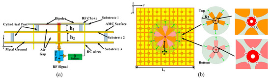
Figure 1.
(a) Configuration of the reconfigurable antenna, (b) top view of the antenna. The parameters of the structure are h1 = 7, h2 = 8, L1 = 105, l = 18, d = 9, R1 = 30, Dg = 0.42 (Units/mm).
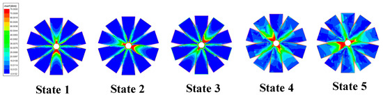
Figure 2.
The current distribution under different linear polarization states.
By sequentially activating the five pairs of semi–elliptical diodes, the effective radiating structure can be rotated by 72° in sequence, thereby changing the polarization orientation. From the above analysis, we can directly relate the controlled current flow to the generated polarization states.
2.2. AMC Unit Design
Generally, a PEC reflector is added under the antenna to generate unidirectional radiation patterns, and it is usually located at a distance of λ/4 from the antenna, which makes the antenna profile too large. Therefore, we can replace the PEC reflector with an AMC structure to achieve a low profile and be able to fulfil the function of a PEC reflector at the same time. The AMC structure is shown in Figure 3a, which contains an AMC surface, a metal ground, and an air medium in between them. Each AMC cell contains a square patch with a square aperture in its center and four rectangular slots on its four sides. Figure 3b illustrates the simulated reflection phase of the different AMC structures. The bandwidth of the in-phase reflection is generally defined as between [−90°, +90°]. From Figure 3b, we can see that AMC 3 has a reflection bandwidth from 2 GHz to 4 GHz (with a fractional bandwidth of 66%), which is much larger than the other two AMC structures. As shown in Figure 3c, different numbers of AMC cells can also affect the antenna performance. In this letter, we select the optimal number of cells (7 × 7) in which the antenna bandwidth is maximum.
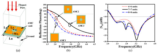
Figure 3.
(a) Structure of the proposed AMC unit, (b) simulated reflection phase of AMC units with different structures, (c) simulated |S11| with a different number of AMC units. The parameters of the structure are Lu = 15, La = 13, Ls = 4, Ws = 6 (units/mm).
3. Antenna Performances
Figure 4 depicts the fabricated prototype of the present proposed multi-linear polarization reconfigurable antenna. We provide DC power to the PIN diodes through the Bias Tee using a 1.5 V battery. The DC wire at the bottom of the antenna connects to the negative end of the battery. In particular, FR-4 is selected as the supporting substrate to achieve a cost-effective and practically manufacturable design, while still enabling high overall antenna performance.
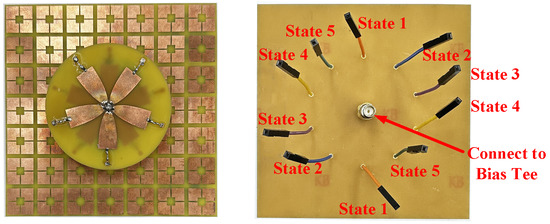
Figure 4.
The fabricated antenna prototype.
To verify the performance of the proposed antenna, Figure 5 demonstrates the simulated and measured results of |S11| and gains for each polarization state of the antenna. Figure 6 shows the simulated and measured normalized radiation patterns for all polarization states at 2.5 GHz and 3.6 GHz in E-plane and H-plane.
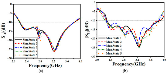
Figure 5.
Simulated and measured |S11| under five different linear polarizations. (a) simulated |S11|, (b) measured |S11|.
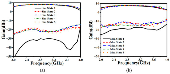
Figure 6.
Simulated and measured gains under five different linear polarizations. (a) simulated gains, (b) measured gains.
Firstly, Figure 5a shows that the measured and simulated |S11| are in good agreement. Although the measured |S11| is worse than the simulated |S11| due to the losses in PIN diodes and choke inductors, the proposed antenna still has a wide −10 dB impedance bandwidth of 50% (from 2.35 GHz to 3.75 GHz) for each polarization state.
As shown in Figure 6, the measured gains are also slightly lower than the simulated gains. However, the maximum gain of this design still reaches 8.1 dBi for each polarization state in the operating frequency band. In addition, the measured cross-polarization gain is also 17 dB lower than the co-polarization gain; the cross-polarization gain of state 1 is even lower by more than 20 dBi. In this antenna design, the five pairs of semi–elliptical dipoles are rotated and placed at an angle of 72° (360°/5). Even though the activated dipole is not perfectly orthogonal to other dipoles, the 72° angular separation can still guarantee good cross-polarization suppression. Furthermore, we can also observe that the result for state one is better than the other four states. This is due to the fact that the remaining four pairs of dipoles are axisymmetric about the dipole in state one.
Then, as observed from the normalized radiation patterns presented in Figure 7, the proposed antenna has stable radiation patterns for all polarization states, and the cross-polarizations are all at a low level (less than 17 dB). Similarly, the cross-polarization ratio of state one is lower than the remaining four polarization states.
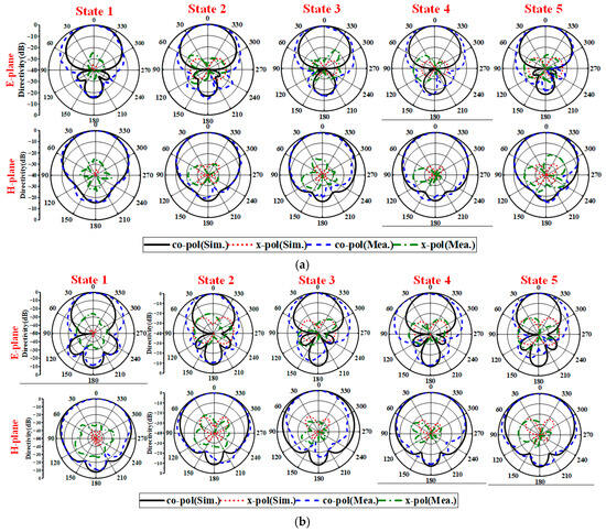
Figure 7.
Simulated and measured normalized radiation patterns at (a) 2.5 GHz and (b) 3.6 GHz.
Finally, Table 1 provides a comparison of the proposed antenna with other published antennas. The proposed antenna combines the advantages of wide bandwidth, high gain, multiple number of linear polarization states, and low profile. Meanwhile, it has a simple structure and easy switching of linear polarization states. This makes the design suitable for modern communication aspects and subsequent communication systems in practice.

Table 1.
Performance Comparison.
4. Conclusions
A wideband, five-linear-polarized reconfigurable antenna with low-profile features is proposed in this paper. The antenna uses five pairs of semi–elliptical dipoles as the main radiators to effectively broaden the operational bandwidth, and the switching of the five linear polarization states is controlled by switching the ON/OFF of the PIN diodes between feeding pads and dipoles to excite a specific pair of dipoles each time. An AMC reflector is employed to obtain a low profile of 0.14λ0. Full-wave simulation shows the proposed antenna has a −10 dB impedance bandwidth of 50% (from 2.35 GHz to 3.75 GHz), stable radiation patterns in each polarization mode, and the cross-polarization levels in both E- and H-planes are less than −20 dB. The maximum gain reaches 8.1 dBi. The proposed antenna has the advantages of wide bandwidth, a high number of linear polarization states, low profile, and high gain, which can be applied to realize arbitrary linear polarization reconfiguration of conformal arrays in radar and military platforms.
Author Contributions
Conceptualization, S.Y. and K.Y.; resources, Y.Z.; data curation, K.Y.; writing—original draft preparation, K.Y.; writing—review and editing, S.Y.; project administration, Y.Z.; funding acquisition, Y.Z. All authors have read and agreed to the published version of the manuscript.
Funding
This research was funded by China Postdoctoral Science Foundation under Grant 2025M774394.
Data Availability Statement
The data are available from the authors upon reasonable request.
Conflicts of Interest
Author Shixing Yu and Yingmeng Zhang were employed by the company AVIC Guizhou Aircraft Co., Ltd. The remaining author declare that the research was conducted in the absence of any commercial or financial relationships that could be construed as a potential conflict of interest.
References
- Yuan, X.; Zheng, S.; Yan, B.; Sheng, W. A Wideband Polarization-Reconfigurable Antenna Based on Fusion of TM10 and Transformed-TM20 Mode. Electronics 2024, 13, 3760. [Google Scholar] [CrossRef]
- Wang, S.; Li, Z.; Chen, M.; Wang, J. A circular-polarization-reconfigurable holographic leaky-wave antenna with fixed-frequency beam-scanning property. IEEE Antennas Wirel. Propag. Lett. 2023, 22, 1266–1270. [Google Scholar] [CrossRef]
- Farzami, F.; Khaledian, S.; Smida, B.; Erricolo, D. Reconfigurable linear/circular polarization rectangular waveguide filtenna. IEEE Trans. Antennas Propag. 2018, 66, 9–15. [Google Scholar] [CrossRef]
- Chen, S.L.; Liu, Y.H.; Zhu, H.; Chen, D.Z.; Guo, Y.J. Millimeter-wave cavity-backed multi-linear polarization reconfigurable antenna. IEEE Trans. Antennas Propag. 2022, 70, 2531–2542. [Google Scholar] [CrossRef]
- Yang, J.; Qi, S.-S.; Wu, W.; Fang, D.-G. A Fabry–Perot Conical Beam Antenna with Multi-Polarization Reconfigurable Capability. IEEE Trans. Antennas Propag. 2022, 70, 11091–11096. [Google Scholar] [CrossRef]
- Kang, L.; Li, H.; Tang, B.; Wang, X.; Zhou, J. Quad-polarization-reconfigurable antenna with a compact and switchable feed. IEEE Antennas Wirel. Propag. Lett. 2021, 20, 548–552. [Google Scholar] [CrossRef]
- Zhang, Z.; Sun, M.; Fu, X.; An, K.; Chen, A. A wideband quad-polarization-agile antenna with 1 b phase-reconfigurable baluns. IEEE Antennas Wirel. Propag. Lett. 2021, 20, 1671–1675. [Google Scholar] [CrossRef]
- Ge, L.; Yang, X.; Zhang, D.; Li, M.; Wong, H. Polarization-reconfigurable magnetoelectric dipole antenna for 5G Wi-Fi. IEEE Antennas Wirel. Propag. Lett. 2017, 16, 1504–1507. [Google Scholar] [CrossRef]
- Kwon, N.; Lee, W. A reconfigurable dual-polarized cavity-backed annular slot antenna for wireless internet of things applications. Microw. Opt. Technol. Lett. 2023, 65, 1719–1727. [Google Scholar] [CrossRef]
- Tran, H.H.; Nguyen-Trong, N.; Le, T.T.; Park, H.C. Wideband and multi polarization reconfigurable crossed bowtie dipole antenna. IEEE Trans. Antennas Propag. 2017, 65, 6968–6975. [Google Scholar] [CrossRef]
- Chen, S.L.; Wei, F.; Qin, P.Y.; Guo, Y.J.; Chen, X. A multi-linear polarization reconfigurable unidirectional patch antenna. IEEE Trans. Antennas Propag. 2017, 65, 4299–4304. [Google Scholar] [CrossRef]
- Wong, H.; Lin, W.; Huitema, L.; Arnaud, E. Multi-polarization reconfigurable antenna for wireless biomedical system. IEEE Trans. Biomed. Circuits Syst. 2017, 11, 652–660. [Google Scholar] [CrossRef] [PubMed]
- Ding, X.; Zhao, Z.; Yang, Y.; Nie, Z.; Liu, Q.H. Wideband Quad-Polarization Reconfigurable Antenna Using Switchable Feed Network with Stable Unidirectional Radiation Patterns. IEEE Access 2018, 6, 73434–73443. [Google Scholar] [CrossRef]
- Liu, M.; Zhai, Z.J.; Lin, F.; Sun, H.J. Wideband Quad-Polarization-Reconfigurable Bidirectional Antenna with a Simple Wideband Switchable Feeding Network. IEEE Antennas Wirel. Propag. Lett. 2023, 22, 6. [Google Scholar] [CrossRef]
- Zhu, H.L.; Cheung, S.W.; Liu, X.H.; Yuk, T.I. Design of polarization reconfigurable antenna using metasurface. IEEE Trans. Antennas Propag. 2014, 62, 2891–2898. [Google Scholar] [CrossRef]
- Chang, L.-H.; Lai, W.-C.; Cheng, J.-C.; Hsue, C.-W. A symmetrical reconfigurable multi polarization circular patch antenna. IEEE Antennas Wirel. Propag. Lett. 2014, 13, 87–90. [Google Scholar] [CrossRef]
- Zhu, H.; Qiu, Y.; Wei, G. A broadband dual-polarized antenna with low profile using nonuniform metasurface. IEEE Antennas Wirel. Propag. Lett. 2019, 18, 1134–1138. [Google Scholar] [CrossRef]
- Singh, J.; Stephan, R.; Hein, M.A. Low-profile wideband differentially fed di-patch antenna closely above metallic ground. IEEE Antennas Wirel. Propag. Lett. 2019, 18, 976–980. [Google Scholar] [CrossRef]
- Liu, Y.; Wang, S.; Wang, X.; Jia, Y. A differentially fed dual-polarized slot antenna with high isolation and low profile for base station application. IEEE Antennas Wirel. Propag. Lett. 2019, 18, 303–307. [Google Scholar] [CrossRef]
- Jiang, Z.; Wang, Z.; Nie, L.; Zhao, X.; Huang, S. A Low-Profile Ultrawideband Slotted Dipole Antenna Based on Artificial Magnetic Conductor. IEEE Antennas Wirel. Propag. Lett. 2022, 21, 671–675. [Google Scholar] [CrossRef]
- Lin, X.; Mai, J.; He, H.; Zhang, Y. Dual-Polarized Dipole Antenna with Wideband Stable Radiation Patterns Using Artificial Magnetic Conductor Reflector. Sensors 2024, 24, 3911. [Google Scholar] [CrossRef] [PubMed]
- Wu, B.; Ji, Y.; Fang, G. Analysis of GPR UWB Half-Ellipse Antennas with Different Heights of Backed Cavity Above Ground. IEEE Antennas Wirel. Propag. Lett. 2010, 9, 130–133. [Google Scholar] [CrossRef]


Disclaimer/Publisher’s Note: The statements, opinions and data contained in all publications are solely those of the individual author(s) and contributor(s) and not of MDPI and/or the editor(s). MDPI and/or the editor(s) disclaim responsibility for any injury to people or property resulting from any ideas, methods, instructions or products referred to in the content. |
© 2025 by the authors. Licensee MDPI, Basel, Switzerland. This article is an open access article distributed under the terms and conditions of the Creative Commons Attribution (CC BY) license (https://creativecommons.org/licenses/by/4.0/).