Abstract
This paper presents a bistatic 60 GHz frequency-modulated continuous-wave (FMCW) radar system for non-contact heart rate monitoring, utilizing high-gain Fabry–Perot cavity (FPC) antennas at both the transmitter and receiver. Each FPC antenna integrates a partially reflective surface (PRS) and a metallic ground plane to form a resonant cavity. Compared to conventional patch arrays of the same aperture, the FPC antenna improves the antenna gain from 4.1 dBi to 8.1 dBi at the transmitter and from 3.9 dBi to 7.8 dBi at the receiver, resulting in an overall link budget enhancement of approximately 7.9 dB. This dual high-gain configuration theoretically increases the maximum detection range by a factor of 2.48. The proposed radar system was implemented and experimentally validated under indoor conditions using both calibration targets and human participants. Active measurement results confirm that the bistatic radar equipped with FPC antennas extends the reliable heart rate detection distance by approximately 2.27 times compared to a conventional system, closely matching the theoretical prediction. These results confirm the practicality and effectiveness of FPC antennas in extending both the range and reliability of millimeter-wave vital sign detection systems.
1. Introduction
Non-contact vital sign monitoring has emerged as a key technology in healthcare, remote patient observation, and emergency response scenarios, offering advantages in convenience, hygiene, and patient comfort. Among various sensing approaches, millimeter-wave frequency-modulated continuous-wave (FMCW) radar has attracted significant attention due to its high spatial resolution, compact antenna size, and robustness to environmental variations [1,2,3,4,5,6,7,8,9]. In particular, 60 GHz radar systems enable sub-millimeter displacement sensitivity, making them well suited for detecting the minute chest wall motions induced by human heartbeat activity.
Despite these advantages, conventional FMCW vital sign radars face critical limitations in detection range. The micro-displacement signals corresponding to heartbeats typically exhibit amplitudes on the order of hundreds of micrometers, resulting in extremely low radar cross-section (RCS) values. As a result, the received signal power decreases rapidly with increasing distance, leading to a sharp drop in signal-to-noise ratio (SNR) and reduced measurement reliability. Although advanced signal processing techniques and higher transmit power have been explored to mitigate this problem, these approaches alone often fail to achieve significant range extension, especially under regulatory limits on equivalent isotropically radiated power (EIRP).
One of the promising candidates for improving the radar link budget is the use of high-gain antennas. Various approaches have been proposed, including transmitarray antennas based on metasurfaces [10,11,12,13,14], which can achieve high gain but often require complex metallic pattern designs and precise fabrication. In contrast, Fabry–Perot cavity (FPC) antennas have drawn interest for their ability to provide narrow beams and substantial gain enhancement while maintaining a relatively low-profile structure and a simple structure [15,16,17,18]. The FPC antenna consists of a partially reflective surface (PRS) and a metallic ground plane, forming a resonant cavity that enhances forward radiation. For the same aperture size, FPC antennas can achieve higher gain compared to the conventional patch antennas, offering clear benefits for long-range vital sign detection such as heart rate.
Although previous works have investigated FPC antennas for remote vital sign detection at 60 GHz, they primarily focus on beam scanning or complex multi-layer structures [19,20]. This study proposes a bistatic 60 GHz FMCW radar system utilizing a fixed-beam, high-gain FPC antenna with a commercially fabricated PRS, offering a simpler design, ease of integration, and practical performance enhancement. Each FPC antenna achieves a gain improvement exceeding 3 dB compared to a reference 2 by 1 patch array, resulting in a combined link budget enhancement of about 8 dB. Experimental validation under indoor conditions demonstrates that this configuration more than doubles the maximum reliable heart rate detection range relative to the conventional system, while maintaining stable phase response and high SNR. Furthermore, the improved spatial selectivity of the FPC antennas effectively suppresses multipath-induced clutter, enhancing detection robustness in realistic environments.
While this study focuses on the experimental validation of bistatic FMCW radar with FPC antenna, it is important to place our approach in the context of other modern vital-sign monitoring techniques. Continuous-wave Doppler radars with beam scanning, MIMO FMCW systems with digital beamforming, and multi-antenna coherent combining have all demonstrated strong potential for improving robustness, range, and adaptability. Furthermore, the integration of advanced algorithms such as MUSIC/DR-MUSIC, wavelet decomposition, and HRV extraction provides significant additional performance gains. Compared with these approaches, the proposed method offers clear advantages in simplicity and hardware efficiency, providing immediate gain enhancement without introducing additional algorithmic or computational complexity. However, the trade-off is the absence of spatial diversity and adaptive processing capabilities available in multi-antenna and algorithm-driven systems.
2. Design of Fabry–Perot Cavity (FPC) Antenna
Figure 1 shows the FPC by a ground and PRS with excitation inside a cavity. The directivity (D) of the FPC antenna is given by [15]
where ΓPRS is the reflection magnitude of PRS and d is a distance between PRS and GND. and are the reflection phase of the PRS and the ground plane, respectively. f is the radiation pattern of the source. From Equation (1), and ΓPRS should be 2πN (N = integer) and close to 1, respectively, to achieve the maximum directivity. Then, the height (d) of the FPC antenna is calculated by Equation (2) and can be determined by the sum of reflection phases of the ground plane and the PRS.
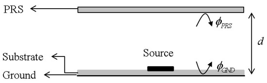
Figure 1.
Fabry–Perot cavity (FPC) by ground and partially reflective surface (PRS) with excitation inside a cavity.
In this study, we designed the FPC antenna to enhance the antenna gain of bistatic 60 GHz FMCW heart rate radar system without increasing the number of array elements. The reference antenna system consists of a 2 × 1 patch array antenna for both the transmitter (Tx) and receiver (Rx), as shown in Figure 2a. The antenna size is 3 mm × 4 mm, and an inset cut technique is utilized to achieve good impedance matching. The feed lines of both Tx and Rx antennas are connected bottom lines through via to connect with the RF circuit on the bottom layer. In addition, due to the opposing orientation of the antennas, a half-wavelength phase delay feed line was implemented in the Rx antenna array to ensure proper phase alignment, as shown in Figure 2a. As illustrated in Figure 2b, the full-wave simulated S-parameters clearly indicate that a resonance occurs at 60 GHz and the good isolation below—40 dB at the resonant frequency. The simulation results are obtained by ANSYS Desktop. To implement the antenna along with the RF circuit realized on the PCB, both antennas were fabricated on an FR4 substrate, which is known to have a relatively high loss tangent of 0.02. Due to this material characteristic, the realized gain of both the Tx and Rx antennas is limited to approximately 4 dBi at operation frequency, even though each antenna is implemented as a 2 × 1 patch array. To improve the antenna performance without expanding the physical size of the antenna or increasing the number of elements, we introduced the PRS with a dielectric constant of 4.3, forming an FPC antenna structure. The PRS was fabricated using a commercial PCB substrate (ZYF-430CA), which has a thickness of 1.6 mm and a loss tangent of 0.0035. The dimension of the PRS is 23 mm × 25 mm, which is the same as the size of the PCB board. Since the PRS has a reflection phase of −150° at 60 GHz, it was placed above the patch antenna with a spacing of 2.7 mm, which was calculated according to Equation (2). Moreover, since the PRS has a reflection coefficient of 0.6 at 60 GHz, a gain enhancement of approximately 6 dB can be theoretically and ideally predicted according to Equation (1). The reflection magnitude and phase of the PRS were obtained using ANSYS Desktop simulation, assuming normal incidence from the far field. The reflection coefficient of the PRS varies from 0.57 to 0.62 across the 58~62 GHz frequency range, while the reflection phase ranges from −144° to −156°. As indicated by Equation (1), an increase in the permittivity of the PRS leads to greater gain enhancement. Nevertheless, for ease of fabrication, a PRS with a relative permittivity of 4.3 was employed in this study. The effectiveness of the proposed FPC antenna design was validated through simulation. The S-parameters showed nearly the same characteristics as in the case without the PRS. Figure 3 shows the full-wave simulated far-field radiation patterns of the Tx and Rx patch arrays without and with PRS. The results clearly demonstrate a significant gain improvement of approximately 4 dB over the conventional patch array, while maintaining acceptable impedance matching. Table 1 summarizes the frequency-dependent gain enhancement, confirming that the FPC maintains high performance throughout the chirp bandwidth.
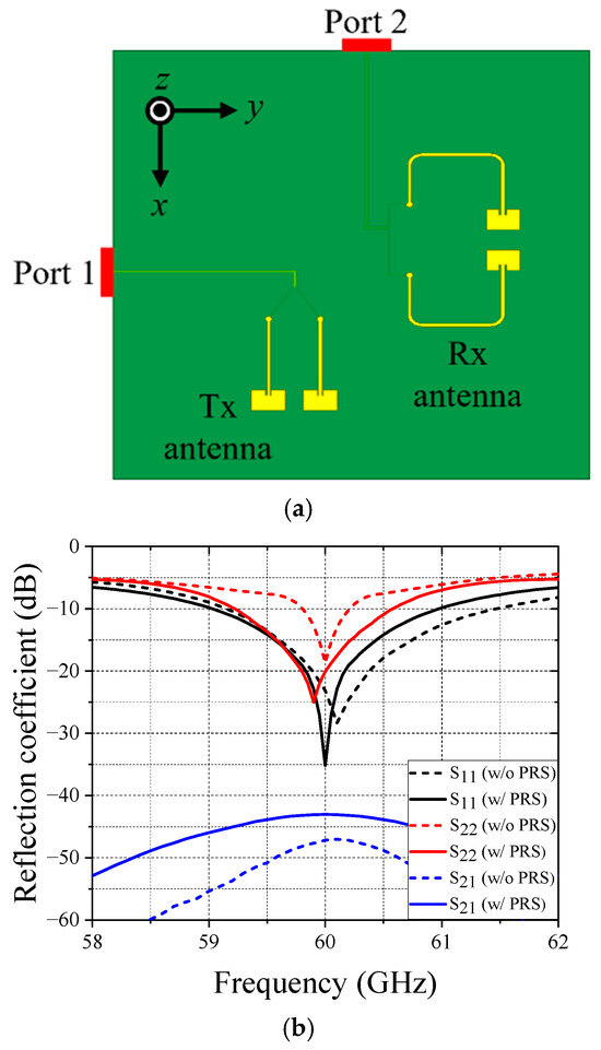
Figure 2.
Tx and Rx antennas of 60 GHz FMCW heart rate radar system. (a) Top view of the antennas. (b) Full wave simulated S-parameters.
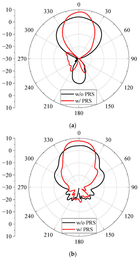
Figure 3.
Full-wave simulated far-field radiation patterns of the Tx and Rx patch arrays without and with PRS (x-z plane) at 60 GHz. (a) Tx antenna. (b) Rx antenna.

Table 1.
Frequency-dependent gain enhancement against chirp frequencies.
3. Experimental Results and Discussion of Bistatic FMCW Radar System
Figure 4 presents a block diagram of bistatic FMCW radar system designed for non-contact detection of heartbeat and respiration. The system operates by transmitting a frequency-modulated chirp signal fTX(t) from a TX antenna towards the chest. The chest’s micro-movements, due to cardiac and respiratory activity, modulate the reflected signal. In the bistatic configuration, the transmitted and received signals are handled by separate antennas, allowing spatial separation between the TX and RX modules. The signal generator produces a linear chirp signal, which is amplified by a power amplifier before transmission through the TX antenna. The reflected signal fRX(t), modulated by the displacement caused by vital signs, is captured by the RX antenna. It then passes through low noise amplifier, and is mixed with a reference copy of the transmitted signal using a mixer to obtain the intermediate frequency (IF) signal. This IF signal contains phase and frequency shifts corresponding to the target’s motion. Subsequently, the IF signal is passed through a filter to suppress noise and out-of-band components, and then amplified via a gain amplifier. The analog signal is converted to digital using an analog-to-digital converter (ADC). Finally, the digital signal is processed using a digital signal processing (DSP) unit, which extracts the heartbeat and respiration rates by analyzing periodic patterns in the phase or frequency domain. Figure 5 shows the FMCW radar module for real-time heartbeat detection. In addition, Figure 5b presents the FPC Tx and Rx antennas with a 2.7 mm spacing between the PRS with a dielectric constant of 4.3 and the ground. Figure 6 is the measurement setup of the FMCW radar system for non-contact heartbeat detection. The radar module is oriented toward the human target, which seated at a distance in front of the radar system. In addition, the height of the radar module was adjusted to be at the same level as the subject’s heart, in order to maximize signal reflection. A total of three human subjects participated in the experiment and the transmit power of the radar system is set to 12 dBm. The measurement environment was arranged to minimize clutter reflectors, with no large metallic or reflective surfaces present within the radar’s field of view. The maximum detection distance was evaluated in the configurations without and with the PRS, and the results were compared to analyze their characteristics. According to the Friis transmission Equation (3), the received power (Pr) at a distance (d) can be expressed.
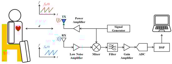
Figure 4.
Block diagram of a non-contact heartbeat monitoring system using FMCW radar.
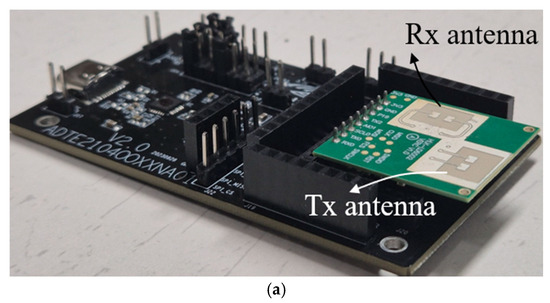
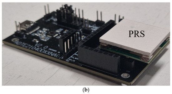
Figure 5.
Photograph of the FMCW radar module for real-time heartbeat detection. (a) Tx and Rx antennas without PRS. (b) Tx and Rx antennas with PRS.
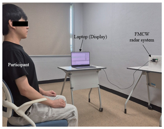
Figure 6.
Measurement setup of the FMCW radar system for non-contact heartbeat detection.
Table 2.
Heartbeat detection success at different distances with and without FPC antennas.
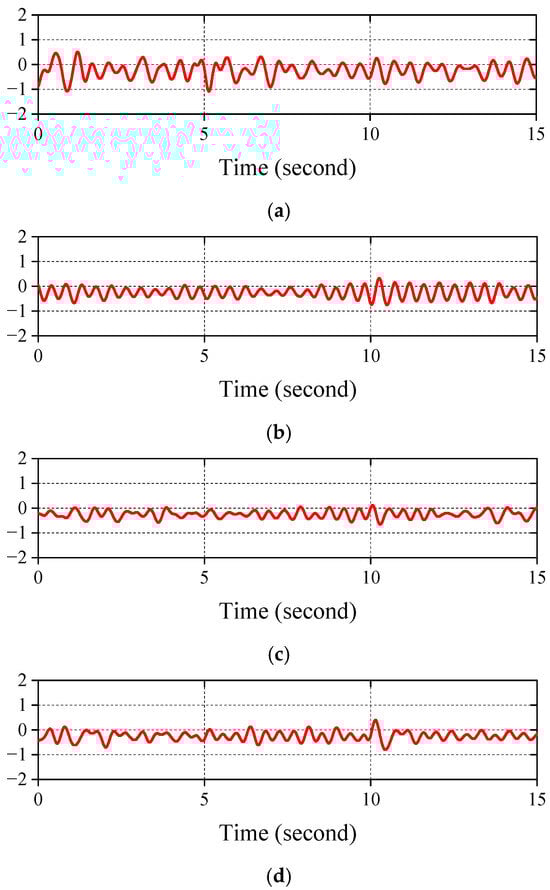
Figure 7.
Measured heartbeat signals against various distance. (a) 0.5 m. (b) 1 m. (c) 1.5 m. (d) 2 m.
4. Conclusions
In this paper, a bistatic 60 GHz FMCW radar system incorporating high-gain FPC antennas was proposed and experimentally demonstrated for non-contact heart rate monitoring. By utilizing PRS and ground plane, the FPC antennas significantly enhanced the overall link performance compared to conventional patch arrays. Experimental results verified that the proposed configuration effectively extends the reliable detection range while maintaining stable phase response and strong signal quality. Additionally, the improved spatial selectivity of the FPC antennas contributed to the suppression of multipath interference, resulting in enhanced robustness under realistic indoor conditions. These findings suggest that FPC antennas offer a practical and effective solution for improving the performance of millimeter-wave vital sign monitoring systems.
Author Contributions
Conceptualization, J.-G.L.; methodology, J.-G.L.; software, H.J.L.; validation, J.-M.J.; formal analysis, H.J.L.; investigation, H.-S.B.; writing—original draft preparation, H.-S.B.; writing—review and editing, J.-G.L.; visualization, J.-M.J. All authors have read and agreed to the published version of the manuscript.
Funding
This work was supported by Innovative Human Resource Development for Local Intellectualization program through the Institute of Information & Communications Technology Planning & Evaluation (IITP) grant funded by the Korea government (MSIT) (IITP-2025-RS-2022-00156361).
Data Availability Statement
The original contributions presented in this study are included in the article. Further inquiries can be directed to the corresponding author.
Conflicts of Interest
The authors declare no conflicts of interest.
References
- Wang, B.; Zheng, Z.; Guo, Y.X. Millimeter-wave frequency modulated continuous wave radar-based soft fall detection using pattern contour-confined doppler-time maps. IEEE Sens. J. 2022, 22, 9824–9831. [Google Scholar] [CrossRef]
- Singh, L.; You, S.; Jeong, B.J.; Koo, C.; Kim, Y. Remote estimation of blood pressure using millimeter-wave frequency-modulated continuous-wave radar. Sensors 2023, 23, 6517. [Google Scholar] [CrossRef] [PubMed]
- Wang, T.; Sun, W.; Shima, K. Continuous body movement-robust respiration rate detection using frequency-modulated continuous wave millimeter wave radar based on non-negative matrix factorization algorithm. Biomed. Signal Process. Control 2025, 102, 107243. [Google Scholar] [CrossRef]
- Li, Y.; Gu, C.; Mao, J. 4-D gesture sensing using reconfigurable virtual array based on a 60-GHz FMCW MIMO radar sensor. IEEE Trans. Microw. Theory Tech. 2022, 70, 3652–3665. [Google Scholar] [CrossRef]
- Nashashibi, A.Y.; Kashanianfard, M.; Sarabandi, K. Calibration of wideband FMCW polarimetric radars operating at millimeter-wave frequencies. IEEE Trans. Geosci. Remote Sens. 2022, 60, 5108010. [Google Scholar] [CrossRef]
- Liu, Z.; Liu, H.; Ma, C. A robust hand gesture sensing and recognition based on dual-flow fusion with FMCW radar. IEEE Geosci. Remote Sens. Lett. 2022, 19, 4028105. [Google Scholar] [CrossRef]
- Zhang, Z.; Zhang, J.; Liu, J.; Li, Y.; Gu, C. Enhanced motion sensing with FMCW radar based on a novel frequency-reconfigurable technique. IEEE Trans. Microw. Theory Tech. 2024, 72, 6187–6199. [Google Scholar] [CrossRef]
- Nallabolu, P.; Zhang, L.; Hong, H.; Li, C. Human presence sensing and gesture recognition for smart home applications with moving and stationary clutter suppression using a 60-GHz digital beamforming FMCW radar. IEEE Access 2021, 9, 72857–72866. [Google Scholar] [CrossRef]
- Liu, S.; Zhao, L.; Yang, X.; Du, Y.; Li, M.; Zhu, X.; Dai, Z. Remote drowsiness detection based on the mmwave FMCW radar. IEEE Sens. J. 2022, 22, 15222–15234. [Google Scholar] [CrossRef]
- Derafshi, I.; Komjani, N. A new high aperture efficiency transmitarray antenna based on Huygens metasurfaces. IEEE Trans. Antennas Propag. 2022, 70, 5458–5467. [Google Scholar] [CrossRef]
- Park, J.H.; Lee, J.G. Simultaneous beam forming and focusing using a checkerboard anisotropic surface. Electronics 2022, 11, 3823. [Google Scholar] [CrossRef]
- Li, T.J.; Wang, G.M.; Cai, T.; Li, H.P.; Liang, J.G.; Lou, J. Broadband folded transmitarray antenna with ultralow-profile based on metasurfaces. IEEE Trans. Antennas Propag. 2021, 69, 7017–7022. [Google Scholar] [CrossRef]
- Reis, J.R.; Vala, M.; Caldeirinha, R.F.S. Review paper on transmitarray antennas. IEEE Access 2019, 7, 94171–94188. [Google Scholar] [CrossRef]
- Lee, J.G.; Lee, J.H. Low-profile high-efficiency transmitarray antenna for beamforming applications. Electronics 2023, 12, 3178. [Google Scholar] [CrossRef]
- Trentini, G.V. Partially reflecting sheet arrays. IRE Trans. Antennas Propag. 1956, 4, 666–671. [Google Scholar] [CrossRef]
- Kwon, T.S.; Lee, J.G.; Lee, J.H. The gain estimation of a Fabry-perot cavity (FPC) antenna with a finite dimension. J. Electromagn. Eng. Sci. 2017, 17, 241–243. [Google Scholar] [CrossRef]
- Lee, J.G. Compact and robust Fabry-perot cavity antenna with PEC wall. J. Electromagn. Eng. Sci. 2021, 21, 184–188. [Google Scholar] [CrossRef]
- Jang, W.; Jeon, Y.G.; Maeng, H.J.; Kim, J.; Kim, D. Novel beam scan method of Fabry-perot cavity (FPC) antennas. Appl. Sci. 2021, 11, 11005. [Google Scholar] [CrossRef]
- Rabbani, M.S.; Churm, J.; Feresidis, A.P. Fabry–Perot Beam Scanning Antenna for Remote Vital Sign Detection at 60 GHz. IEEE Trans. Antennas Propag. 2021, 69, 3115–3124. [Google Scholar] [CrossRef]
- Mingle, S.; Kampouridou, D.; Feresidis, A. Multi-Layer Beam Scanning Leaky Wave Antenna for Remote Vital Signs Detection at 60 GHz. Sensors 2023, 23, 4059. [Google Scholar] [CrossRef] [PubMed]
Disclaimer/Publisher’s Note: The statements, opinions and data contained in all publications are solely those of the individual author(s) and contributor(s) and not of MDPI and/or the editor(s). MDPI and/or the editor(s) disclaim responsibility for any injury to people or property resulting from any ideas, methods, instructions or products referred to in the content. |
© 2025 by the authors. Licensee MDPI, Basel, Switzerland. This article is an open access article distributed under the terms and conditions of the Creative Commons Attribution (CC BY) license (https://creativecommons.org/licenses/by/4.0/).