Article

A Robust Design Strategy for Resonant Controllers Tuned Beyond the LCL-Filter Resonance Frequency

1
School of Automation, Northwestern Polytechnical University, Xi’an 710129, China
2
School of Automation Engineering, University of Electronic Science and Technology of China, Chengdu 611731, China
3
Energy Technology, Aalborg University, 9220 Aalborg, Denmark
*
Author to whom correspondence should be addressed.
Electronics 2025, 14(20), 3991; https://doi.org/10.3390/electronics14203991
Submission received: 9 September 2025 / Revised: 8 October 2025 / Accepted: 10 October 2025 / Published: 12 October 2025

Abstract

Compared to the L-filter, the LCL-filter provides superior high-frequency harmonic attenuation for a given inductance. However, it also introduces resonance issues that can compromise system stability. Consequently, the bandwidth of the inner current loop must be maintained well below the resonant frequency of the filter. This paper proposes a robust controller design strategy for LCL-filtered converters to extend the harmonic control range under wide variations in grid impedance. An analysis of the resonant controller phase-frequency characteristics reveals its capability to provide phase compensation up to 2π. Building on this finding, the damping ratio and phase leading angle are systematically optimized through a joint analysis of the phase characteristics introduced by the resonant controller and active damping, thereby enhancing system robustness. With these optimized parameters, the center frequency of the resonant controller can be tuned above the LCL-filter resonance frequency without inducing instability. In contrast to conventional methods, the proposed approach allows the LCL-filter to be designed with a lower resonance frequency. This enables improved attenuation of switching-frequency harmonics without compromising the tracking performance for higher-order harmonics. Such a capability is particularly beneficial in high-power and weak-grid scenarios, where the filter resonance frequency may fall to just a few hundred hertz. Experimental results validate the effectiveness of the proposed design strategy.

1. Introduction

Driven by economic and environmental issues, dispersed energy resources (DERs), such as wind turbines (WT) and photovoltaic (PV) arrays, are combined with advanced power electronics systems and integrated into power grids [1,2,3]. Power electronic converters play an active role in distributed power generation, as they bridge the DERs and the power grid. Generally, pulse width modulation (PWM) is commonly used to generate switching signals for converters. However, a principal disadvantage of this methodology is the inherent generation of high-order harmonic content, predominantly at the switching frequency and its multiples, thereby causing a deterioration in grid power quality. To mitigate these high-frequency harmonics, an L-type or LCL-type low-pass filter is usually implemented between the converter and the grid to provide necessary attenuation.
Compared with the L-filter, the LCL-filter can provide better high-frequency harmonic attenuation with the same value of inductance [4,5,6,7]. However, along with the advantages that the LCL-filter brings, the well-known resonance peak and 180° phase jump are also induced, which make the controller design more challenging [8,9,10,11,12,13,14,15,16,17].
One of the easiest ways to damp the LCL-filter resonance peak is by simply inserting a resistor in series with the filter capacitor [8]. In this way, the filter resonance peak can be damped at the expense of reduced system efficiency. In order to avoid the power losses caused by the damping resistor, so-called active damping [7,9,10,11,12,13,14] is proposed by feeding back measurable electrical variables into the control loop to adjust the system damping factor, e.g., capacitor current feedback.
Previous research has explored various design strategies for LCL-filters and control loops. For instance, ref. [11] investigates the influence of system delays on capacitor current feedback active damping and improves robustness against grid impedance variations by aligning the capacitor current sampling instant with the PWM reference update. Furthermore, refs. [12] introduces a delay compensation method to ensure system stability. Building on this, studies [13,14] demonstrate that directly reducing system delay through the multi-sampled PWM (MS-PWM) method can maintain robust stability up to twice the switching frequency.
The aforementioned strategies can enhance the system robustness against grid impedance variations. However, the inherent 180° phase lag introduced by the filter resonance frequency necessitates setting the system crossover frequency well below the resonance frequency to maintain an adequate phase margin [11,12,13]. This design constraint, in turn, degrades the system’s performance in rejecting or injecting high-order harmonics. In order to enhance the high-order harmonic tracking capability, passivity-based and virtual RC damper-based controller tuning strategies are proposed in [15] and [16], respectively. Meanwhile, by carefully designing the LCL-filter parameters, a shunt active power filter (SAPF) is designed in [18] and [19] respectively to effectively compensate high-order harmonic currents without triggering system instability issues. In [20,21], simplified resonant controller tuning strategies are proposed with enhanced performance. In [22], bilateral Bode plots are utilized to optimize the phase leading angle of the resonant controller under low-carrier-ratio conditions.
However, the above-mentioned controller and LCL-filter design strategies lack detailed analysis regarding the influence of the system damping ratio on the controller design principle, and the harmonic controller is generally required to be tuned below the filter resonance frequency to ensure system stability. This results in the converter lacking the controllability of high-order harmonics (adjacent to and higher than the filter resonance frequency), which is undesirable in applications with a low LCL-filter resonance frequency (e.g., several hundred hertz in high-power applications [23]). It is also worth noting that in [16], harmonic compensation up to the 43rd order (2.15 kHz) is achieved by tuning the LCL-filter resonance frequency to 2.6 kHz, which is still much higher than the central frequency of the highest-order resonant controller.
Moreover, grid impedance variation is also a critical issue for harmonic compensation, since it may cause resonance frequency reduction. Conventionally, this issue is resolved by compromising harmonic control capability, i.e., by avoiding tuning harmonic controllers close to the LCL-filter resonance frequency [16,17,18,19]. Although this approach can keep the system stable, the current quality may be degraded, since high-order harmonics remain uncontrolled. Furthermore, considering wide-range grid impedance variations in weak grids, the highest frequency of the controlled harmonic current should be further decreased, which will lead to the deterioration of current quality. It is worth noting that previous works are validated across diverse grid scenarios (e.g., frequency variations and load changes). This paper presents a theoretical analysis with validation under a defined set of conditions. An exploration of the proposed method under diverse grid scenarios is planned for our future work, including a more comprehensive analysis of its performance.
In light of the above-mentioned issues, it is proposed in this paper that by coordinating the system damping ratio and the phase leading angle induced by the resonant controller, the central frequency of the resonant controller can be tuned above the filter resonance frequency without triggering instability issues, even with wide range of grid impedance variations. Consequently, high-order harmonics can be suppressed, which leaves the grid current with improved power quality. The rest of the paper is organized as follows: Section II gives a detailed system characteristic analysis, while Section III illustrates the proposed controller design method. Experimental results are analyzed and discussed in Section IV. Finally, Section V presents the conclusion of the paper. Part of this paper was presented at the IEEE Applied Power Electronics Conference and Exposition [24]. Compared to prior work, this paper adds a comprehensive analysis of the resonant controller compensation capabilities, an in-depth stability analysis of the system, and a detailed performance evaluation of the proposed controller.

2. System Modeling and Analysis

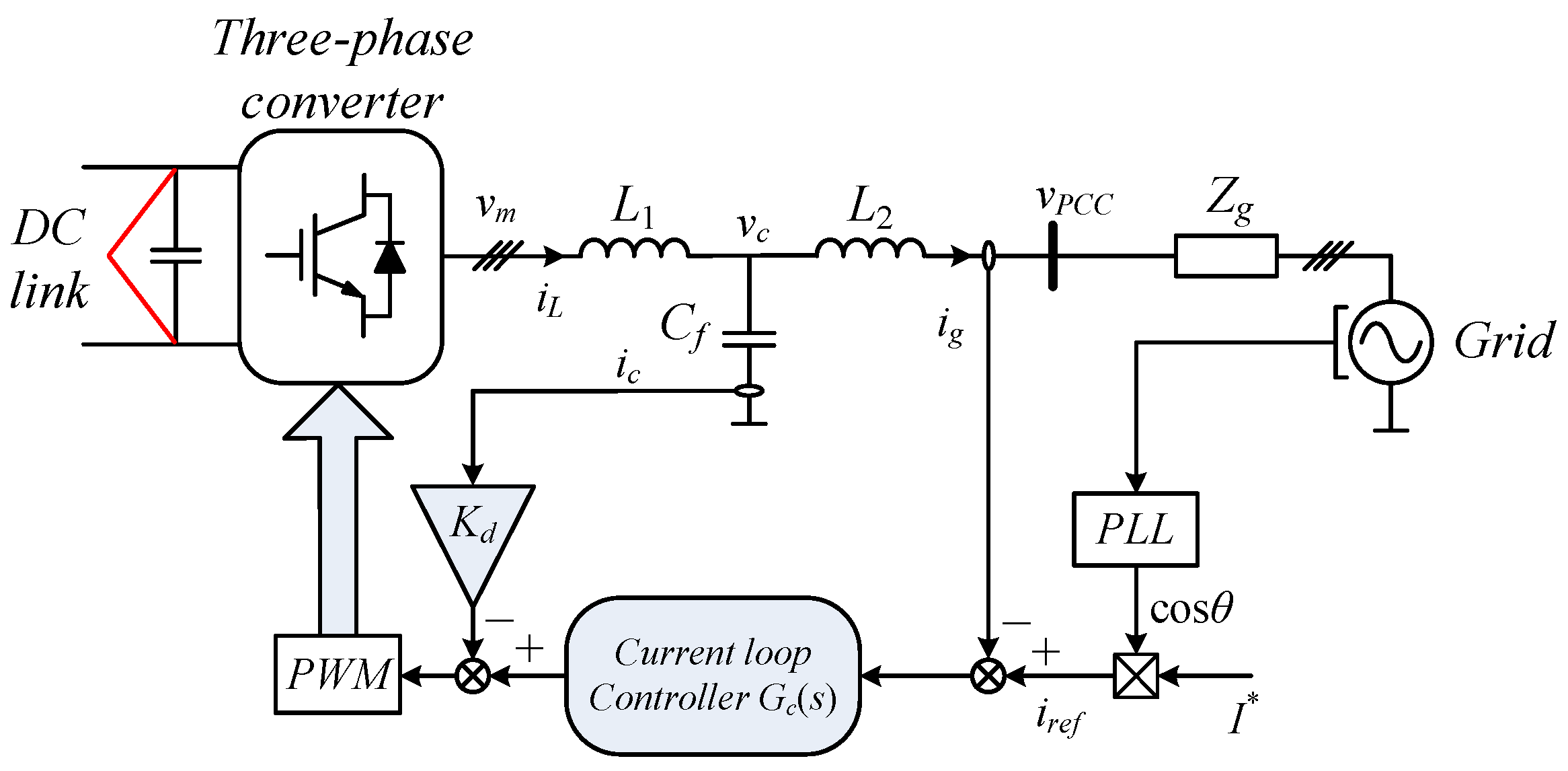
The system under study, which is a general case of an LCL-filter-based grid-connected system, is shown in Figure 1. The grid is represented by its Thévenin equivalent, comprising an ideal sinusoidal voltage source in series with a grid impedance Zg. L1, L2, and Cf denote the converter-side inductor, grid-side inductor, and filter capacitor, respectively, while vm, vc, iL, and ig represent the converter output voltage, capacitor voltage, converter-side current, and grid-injected current, respectively.
A phase-locked loop (PLL) is employed to synchronize the current reference iref with the grid voltage vg. Resonance damping is achieved through capacitor current feedback active damping. It should be noted that the outer DC voltage control loop—which generates the active current reference I*—is not addressed in this paper, as its bandwidth is significantly lower than that of the inner current loop, rendering their dynamic interaction negligible in this context.
By neglecting the parasitic parameters of the LCL-filter, the power plant model is illustrated in Figure 2. The s-domain transfer function from vm to ig is then shown in Equations (1) and (2).
G p a ( s ) = 1 s L 1 L 2 C f s 2 + K d L 2 C f s + ( L + L 2 ) = 1 L 1 L 2 C f 1 s s 2 + 2 ξ ω r e s s + ω r e s 2
K d = 2 ξ L 2 ω r e s = 2 ξ L 2 L 1 + L 2 L 1 L 2 C f
where Kd denotes the capacitor current feedback gain, ξ denotes the damping ratio, and ωres denotes the LCL-filter resonance frequency. From Equation (1), it can be seen that by properly tuning the feedback gain Kd, a second-order system with the desired damping ratio can be obtained. The system parameters used both in the analysis and the experiments are listed in Table 1.
Figure 3 shows the Bode plots of Gpa(s) with different damping ratios. As observed, while the resonance peak is effectively damped, a 180° phase shift is simultaneously introduced. For frequencies below ωres, the phase response starts at −π/2 and decreases monotonically to −π at the resonance frequency. Consequently, conventional design principles mandate that the highest controlled harmonic frequency must not approach ωres to ensure sufficient phase margin.
At frequencies above ωres, the phase further decreases from −π, eventually reaching −3π/2. Given this characteristic, controlling harmonics beyond the resonance frequency appears infeasible with common compensation methods (e.g., lead–lag compensation); consequently, few publications have addressed this challenge. Furthermore, non-negligible PWM and computational delays introduce additional phase lag, causing the system phase at high frequencies to fall below −3π/2. This further complicates the control of harmonic currents at frequencies exceeding ωres.
Assuming the current controller is implemented in the αβ frame with the following expression:
G c f ( s ) = k p i 1 + 1 τ s s 2 + ω f 2
where kpi and τ are the proportional coefficient and integral time constant, respectively, and ωf is the fundamental angular frequency.
The controller parameters can be designed as [25]
k p i = 2 π f c ( L + L g )
τ = ( L + L g ) / ( r + r g )
where fc is the crossover frequency and r and rg are the parasitic resistance of the filter inductor. Considering the 180° phase shift induced by the LCL-filter, fc should be 0.3 times smaller than the filter resonance frequency to avoid instability issues.
Apart from fundamental current tracking, harmonic controllability is also a critical issue for grid-connected converters. Generally, multiple parallel resonant controllers [26] are adopted to provide high gains as well as compensate for system delays at desired harmonic frequencies. The controller can be expressed as
G r e s d ( s ) = h = 5 n k r e s s cos φ c h ω f sin φ c s 2 + ( h ω f ) 2
where kres is the resonant controller gain, n is the highest harmonic order that can be compensated, h is the harmonic order that needs to be compensated for, and φc is the induced phase leading angle at the resonant frequency. Conventionally, the value of f is required to be sufficiently lower than ωres to avoid instability issues caused by the system phase lag. Note that a synchronous reference frame phase-locked loop (SRF-PLL) is employed to update the center frequency of the resonant controller. The PLL bandwidth is set to 10 Hz to achieve a suitable trade-off between tracking speed and noise immunity, thereby ensuring stable estimation of the frequency and phase angle for the controller. As the PLL serves primarily to adjust the center frequency of the resonant controller, its detailed design—being well-established in the literature [27]—is not addressed in this paper.
Then, the system model is depicted in Figure 4. In the figure, Gdelay(s) is the time delay induced by calculation and the PWM process and Gc(s) is the current loop controller which includes both Gcf(s) and Gresd(s). Consequently, the open-loop transfer function of the system is derived as
G o l ( s ) = G c ( s ) G d e l a y ( s ) G p a ( s )
Normally, φc is tuned to be equal with the inverse of the system phase angle [28] to achieve a high compensation accuracy and stability margin, as shown in Equation (8).
φ c = arg [ G d e l a y ( s ) G p a ( s ) ] | s = j h ω f
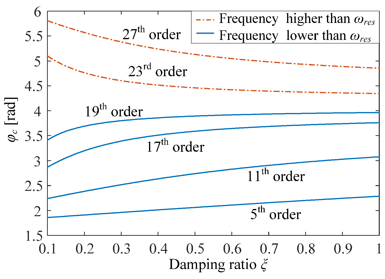
Considering that Gpa(jhωf) is a function of ξ, the relationship between ξ and φc is plotted in Figure 5 for different harmonic frequencies. From Figure 5, it can be found that the damping ratio has different influences on the phase leading angles at different harmonic frequencies. For the harmonics with a frequency lower than ωres, the changing trend of leading angles versus the damping ratio tends to increase. Meanwhile, the trend becomes opposite for the harmonics with a frequency higher than ωres.
In the conventional controller design method, ξ is selected before designing resonant controllers. Thus, the system phase delay is fixed and φc can be obtained directly from Equation (8). Under this condition, the influence of different ξ on φc and the system stability margin is neglected. Thus, to enhance system stability and harmonic controllability, the influence of ξ and φc on system stability should be analyzed. It is found that by properly coordinating ξ and φc, it is possible to control high-order harmonics even if their frequency is higher than ωres.
Moreover, the resonant controller with phase compensation is utilized in the control loop to add a control freedom to the system phase angle, and to the best of the authors’ knowledge, detailed analysis regarding phase compensation range of the resonant controller was not presented in detail in the previous publications. Thus, it is critical to examine the limit of the leading angle before designing the controller parameters.
From the transfer function shown in Equation (6), Gresd(s) can be grouped in the sets of Table 2 based on the signs of sinφc and cosφc, and the corresponding pole/zero (PZ) map and Bode diagram are depicted in Figure 6. Before analyzing the phase characteristic of Gresd(s), it is worth mentioning that a right-half-plane (RHP) zero will induce a π/2 phase lag to the phase characteristic, while a π/2 phase lead is induced if a left-half-plane (LHP) zero is presented [29]. The initial phase angle of Gresd(s) is determined as:
arg [ G r e s d ( s ) ] = arg [ lim ω 0 + k r e s j ω cos φ c h ω f sin φ c ( j ω ) 2 + ( h ω f ) 2 ] = arg [ sin φ c ]
From Equation (9), it can be seen that a positive sinφc will set the initial phase angle as π, while a negative sinφc will set the system initial phase angle as 0. In a similar way, positive and negative signs of cosφc will drive the system final phase angles to be −π/2 and π/2, respectively. Thus, with different combinations of zero positions and φc values, different phase responses of the resonant controller can be obtained. For instance, the signs of sinφc and cosφc are both positive for group A. Consequently, the phase response of Gresd(s) in group A starts from π and ends at −π/2. Meanwhile, due to the RHP zeros in group A, a π/2 phase lag is induced, and this phase lag allows the phase angle at the resonant frequency to be flexibly reduced by tuning φc. This phase reduction results in the phase lead at the resonant frequency lying in the range of (0, π/2) for group A:
0 < arg [ lim ω h ω f k r e s j ω cos φ c h ω f sin φ c ( j ω ) 2 + ( h ω f ) 2 ] < π 2
Similarly, the phase lead at the resonant frequency for groups B, C, and D lies in the range of (π/2, π), (π, 3π/2), and (3π/2, 2π), respectively. Based on the above-mentioned analysis, phase lead provided by the resonant controller can cover a range from 0 to 2π.
Moreover, this conclusion can also be verified by the Bode diagram shown in Figure 6b, which includes the four groups of resonant controllers. This important feature lays the theoretical foundation for delay compensation for harmonics higher than the LCL-filter resonance frequency, where the phase angle of the power plant is below −π.

3. Proposed Controller Parameter Optimization Method

3.1. Active Damping Gain Design

In order to properly design the controller parameters, the z-domain transfer function of the plant is derived. The open-loop system can be regarded as two cascaded parts: from converter output voltage to capacitor current and from capacitor current to grid current. The corresponding transfer functions are shown as [16]
G m c ( z ) = i c ( z ) v m ( z ) = sin ( ω r e s T s ) ω r e s L z 1 z 2 1 2 z 1 cos ( ω r e s T s ) + z 2
G c g ( z ) = i g ( z ) i c ( z ) = T s 2 z 1 L g C f ( 1 z 1 ) 2
Consequently, the discretized block diagram of the system can be shown as Figure 7, and the corresponding open-loop transfer function is derived in the z-domain as:
G o l ( z ) = G c z G p a ( z ) = G c z z 1 G m c ( z ) G c g ( z ) 1 + z 1 K d G m c ( z )
where Gpa(z) is the discretized power plant transfer function. The resonant controller in this work is implemented using the two-integrator structure and discretized via the impulse-invariant (IMP) method [28], a combination chosen to achieve an effective balance between computational efficiency and performance accuracy. Furthermore, the proposed phase leading angle design method is presented as a universal compensation strategy, which is applicable to different kinds of resonant controller implementations. The discretized transfer function of the resonant controller with phase compensation can be shown as
G r e s d ( z ) = k r e s T s cos φ c z 1 cos φ c h ω f T s 1 2 z 1 cos h ω f T s + z 2
To find the system’s most robust operation point and check the influence of controller parameters on the system stability boundary, the sensitivity function S(z) [28,29], which measures the system stability margin using the distance from the Nyquist trajectory to the critical point, is derived as:
S ( z ) = 1 1 + G o l ( z )
A large value of |S(z)| indicates a Nyquist curve approaching the point of instability, and the maximum value of |S(z)| offers a more accurate measure of stability margin than either phase margin or gain margin indicates.
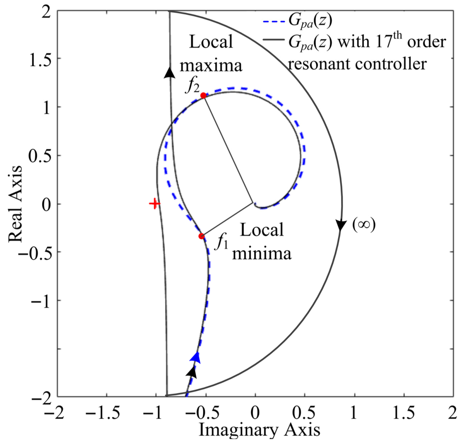
The influence of the damping ratio on the system stability margin is first evaluated using the Nyquist plot of Gpa(z), as shown in Figure 8. The dashed curve represents the system without a resonant controller, while the solid curve corresponds to the system with a 17th-order resonant controller implemented. As frequency increases, the magnitude of the open-loop transfer function (i.e., the distance from the origin to the dashed curve) initially decreases, reaching a local minimum at frequency f1, then increases to a local maximum at f2. Due to the system’s low-pass nature, the Nyquist curve eventually decays toward the origin. A similar magnitude variation can be observed in Figure 3 (e.g., for ξ = 0.1), where a resonance peak appears under low-damping conditions.
When a resonant controller with a center frequency between f1 and f2 is introduced, the corresponding Nyquist curve (solid line) tends toward an infinite magnitude near that frequency, as shown in Figure 8. This behavior results from the resonant controller’s theoretically infinite gain and its associated 180° clockwise phase shift at the center frequency. It should be noted that adjusting the phase leading angle of the resonant controller alters the direction in which the Nyquist curve approaches infinity, thereby influencing the system stability characteristics.
Apparently, due to the monotonically increasing characteristic of the magnitude of Gpa(z) between f1 and f2, the infinite magnitude and 180° phase shift induced by the resonant controller will drive the system Nyquist curve approaching the critical point, finally leading to the reduction of the system stability margin.
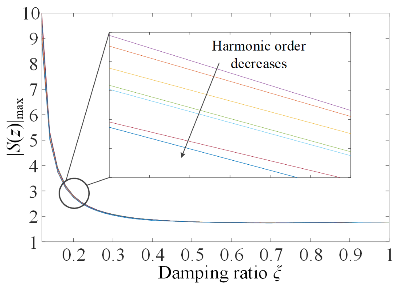
To clearly show the relationship between damping ratio (i.e., magnitude of Gpa(z)) and stability margin, a maximum value of |S(z)| is plotted in Figure 9 as a function of damping ratio with 5th-, 7th-, 11th-, 13th-, 17th-, 19th-, 23rd-, or 25th-order resonant controllers implemented, respectively. As can be seen, |S(z)|max decreases (stability margin increases) as the damping ratio increases, regardless of which order resonant controller is implemented. This is due to the fact that the increase in damping ratio will reduce the magnitude of Gpa(z). Consequently, the Nyquist curve can be maintained further from the critical point, thereby increasing the stability margin. Moreover, since the center frequency of the high-order resonant controller lies farther from the critical point than the lower order resonant controller, it has minimal impact on the proximity of the system Nyquist curve to that point. As a result, |S(z)|max decreases slightly with decreasing harmonic order. It can also be observed from Figure 9 that the system stability margin remains largely unchanged for damping ratios greater than 0.3.
To preserve system stability when implementing high-order resonant controllers, the lower boundary of the damping ratio should be configured to ensure the system magnitude |Gpa(z)| is a monotonically decreasing function. This requirement yields the following constraint on ξ:
G p a ( ω , ξ ) ω < 0
Meanwhile, the upper boundary of ξ is defined to guarantee the open-loop system has a sufficient phase margin φm [10,11,12,13,14,15,16,17,18]. Assuming that ωc is the system crossover frequency, φm can be represented as Equation (17) by substituting z in Gpa(z) with e j ω c . Then, the upper boundary of ξ can be obtained by letting φm > π/3.
φ m = π + arg { G p a ( e j ω c ) } = π + arg { G m c ( e j ω c ) G c g ( e j ω c ) e j ω c + K d G m c ( e j ω c ) } > π 3
Then, the lower and upper boundaries of ξ are derived in Equation (18) based on Equations (16) and (17).
g 1 ( ξ , ω ) | | G p a ( ω , ξ ) | ω = 0 < ξ < g 2 ( ξ , ω ) | φ m = π / 3
where g1(ξ, ω) and g2(ξ, ω) are the constraint functions of ξ obtained from Equations (16) and (17), respectively.

3.2. Phase Leading Angle Optimization

This section details the design of the phase leading angle to maximize the stability margin of an LCL-filter-based grid-connected converter. The system is designed to compensate harmonic currents up to the 23rd order, with key specifications provided in Table 1. With the 1.02 kHz resonance frequency, the current loop bandwidth is determined as 250 Hz to avoid instability issues. Then, the fundamental current controller parameters are eventually determined as kpi = 5.6 and τ = 0.036 s. Using Equations (16)–(18), the range of ξ can be calculated as 0.25 < ξ < 0.52 and the range of Kd can be calculated as 5.8 < Kd < 12. Finally, ξ is chosen as 0.4, with a calculated Kd = 9.2.
The system stability margin is evaluated using the sensitivity function, and a generalized design methodology is presented to maximize this margin. Since the resonant controller has negligible impact on the system frequency characteristics away from its resonance frequency, the phase leading angle for each harmonic frequency can be designed independently.
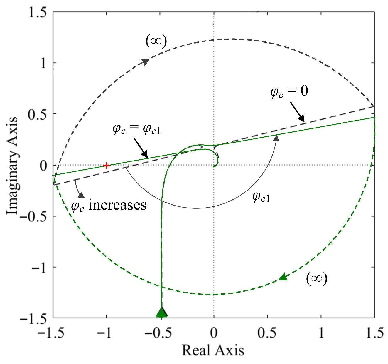
Figure 10 shows the Nyquist diagram of Gol(z) with a resonant controller tuned to a specific harmonic order using different phase leading angles. When φc = 0, the Nyquist curve (dashed line) encircles the critical point, indicating system instability. As φc increases from 0 to φc1, the curve rotates counterclockwise and passes directly through the critical point (solid line), resulting in marginal stability. Further increasing φc from φc1 to 2π moves the curve away from the critical point, establishing stable operation. This progression demonstrates how the system stability margin, quantified by |S(z)|, varies with the phase leading angle.
Thus, to analyze the influence of the phase leading angle on system stability margin, |S(z)|max of the system shown in Figure 10 is plotted in Figure 11 as a function of the phase leading angle. Note that the infinite value of |S(z)|max indicates the Nyquist curve goes through the critical point.
Based on Figure 10, it can be concluded that in order to achieve a stable system, the value of φc should be limited in the range of φc1 and 2π. This stable region contains three stages of |S(z)|max variation, as shown in Figure 11. The sharp decrease in |S(z)|max in Stage I (between φc1 and φcmin) is caused by the Nyquist curve rotating away from the critical point. In Stage II (between φcmin and φc2), |S(z)|max remains relatively stable. Afterwards, the Nyquist curve rotates towards the critical point in Stage III (between φc2 and 2π), and the value of |S(z)|max increases significantly, as illustrated in Figure 11. Note that |S(z)|max has a period of 2π.
Conventionally, the phase leading angle is set to match the system delay to maximize compensation accuracy. However, in high-frequency applications, where stability takes precedence over accuracy, the leading angle must be designed to maximize the stability margin. As illustrated in Figure 11b, although the minimum value of |S(z)|max occurs at φcmin, this point is too close to the unstable boundary at φc1, making the system vulnerable to parameter drift. To ensure sufficient robustness, the optimized phase leading angle φopt is selected as the average of φcmin and φc2. This value is deliberately positioned in the middle of Stage II, thereby providing a wide stability margin.
Moreover, considering that the active damping significantly influences the system phase lag, the designed phase leading angle needs to be recalculated if the damping ratio changes. By following this design procedure, resonant controllers tuned at the 5th-, 7th-, 11th-, 13th-, 17th-, 19th-, and 23rd-order harmonics are designed to maximize the system stability margin, and all the designed controller parameters are listed in Table 3.
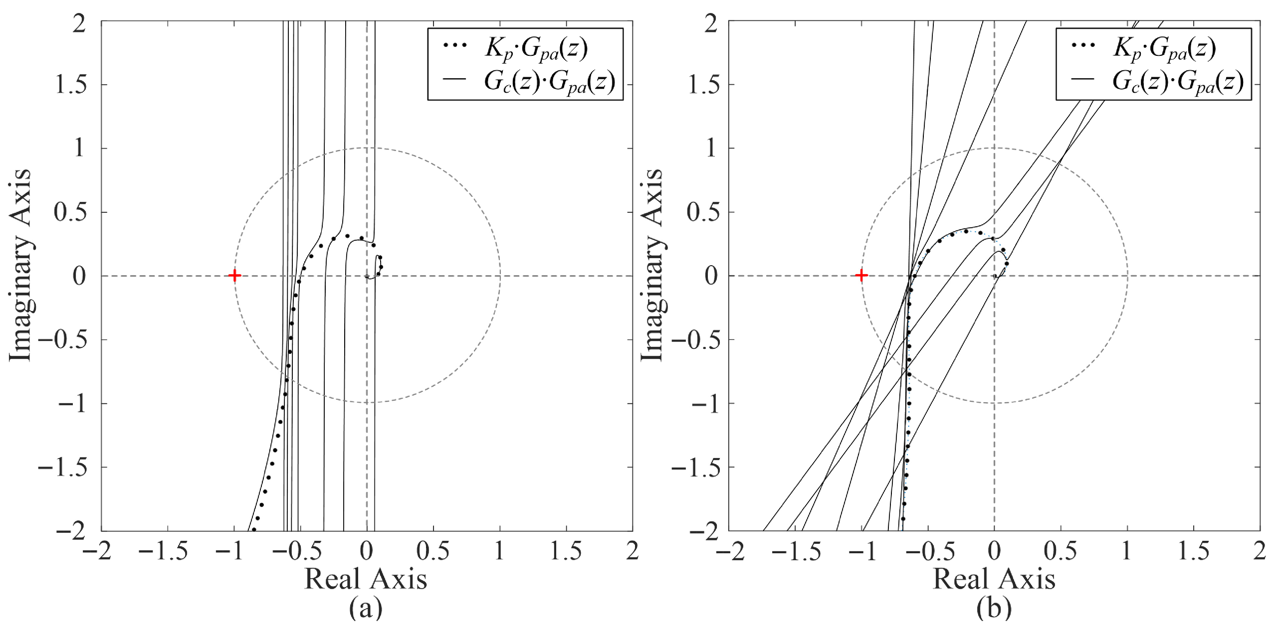
For evaluating the system stability and robustness, subject to wide-ranging grid inductance variations with the designed parameters, a Nyquist diagram of the system is plotted in Figure 12 with two different grid impedance values. Note that Gc(z) includes all the designed resonant controllers. Figure 12a shows the Nyquist curve for a 1.02 kHz resonance frequency and Lg = 0 mH system. It can be seen that thanks to the phase lead induced by the resonant controller, the critical point is no longer encircled compared with the curve shown in Figure 10. Moreover, the Nyquist curve stays far from the critical point, which indicates the system has a large stability margin.
Meanwhile, an 8 mH grid inductance, which decreases the LCL-filter resonance frequency to 800 Hz, is added, and the corresponding Nyquist curve is shown in Figure 12b. It can be seen from the figure that as the grid inductance increases, the phase angle around the resonance frequency also increases. Fortunately, the critical point is still not encircled by the Nyquist curve, which indicates that the system remains stable.
Moreover, the absolute values of the sensitivity function (|S(z)|) for the two systems are shown in Figure 13, which indicates that the |S(z)| values for the two situations are almost the same. Thus, it can be concluded that the system stability margin only slightly degrades as the grid inductance increases. Note that 17th-, 19th-, and 23rd-order (all higher than filter resonance frequency) resonant controllers all remain enabled in both systems.
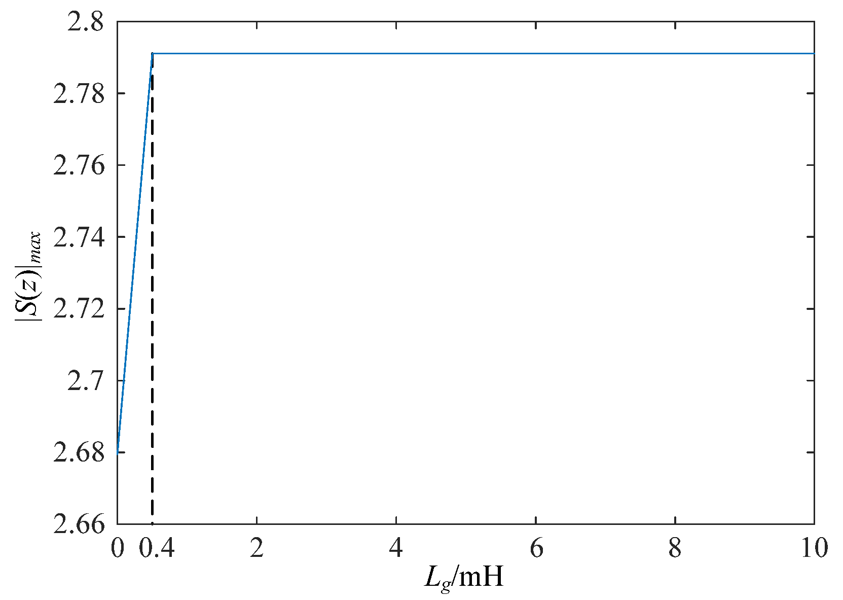
To assess the stability boundary of the system under grid impedance variations, the maximum value of the sensitivity function S(z) with Lg ranging from 0 to 10 mH is shown in Figure 14. As shown, |S(z)|max reaches its peak when the grid inductance is 0.4 mH. Beyond this value, further increases in inductance cause |S(z)|max to remain nearly constant, indicating that system stability becomes largely insensitive to variations in grid impedance. This finding is further verified by the experimental results presented in Section 4.
In conclusion, the controller parameters should be designed in two steps: (a) selecting an appropriate damping ratio to make Gpa(z) a monotonically decreasing function; (b) optimizing the phase leading angle to maximize the system stability margin. After determining all the control parameters, a Nyquist curve with all the resonant controllers enabled should then be drawn for evaluating the system stability.

4. Experimental Results

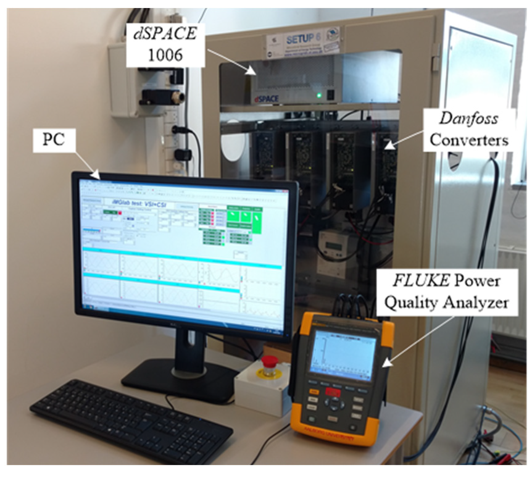
The proposed control strategy was validated through experimental studies performed on the platform shown in Figure 15. The setup comprises two 2.2 kVA Danfoss converters in a three-phase three-leg configuration with LCL-filters. One converter acts as the current-controlled converter under test, while the other emulates the grid. The power stage and control system specifications are provided in Table 1 and Table 3, respectively. A dSPACE 1006 system was used for control implementation, and a FLUKE 437-II power quality analyzer was employed to monitor harmonic performance. Note that the Fluke 437-II complies with the IEC 61000-4-7 standard [30], and the measurement accuracy for voltage and current harmonic amplitudes is specified as ±(0.1% + n × 0.1%).
The computational burden of parallel resonant controllers can be alleviated through the following approaches if a processor with limited computational power is utilized: First, implementing the controller in the synchronous reference frame allows both positive- and negative-sequence harmonics of each harmonic pair to share the same frequency, enabling them to be regulated simultaneously by a single resonant controller. Second, a down-sampling technique can be applied, which lowers the execution rate of the controllers while maintaining the original sampling rate of the system, thereby halving the computational load per cycle compared to a full-rate implementation [31]. Third, the use of a reduced-order resonant controller—replacing the standard second-order integrator with a first-order structure—further decreases computational requirements.
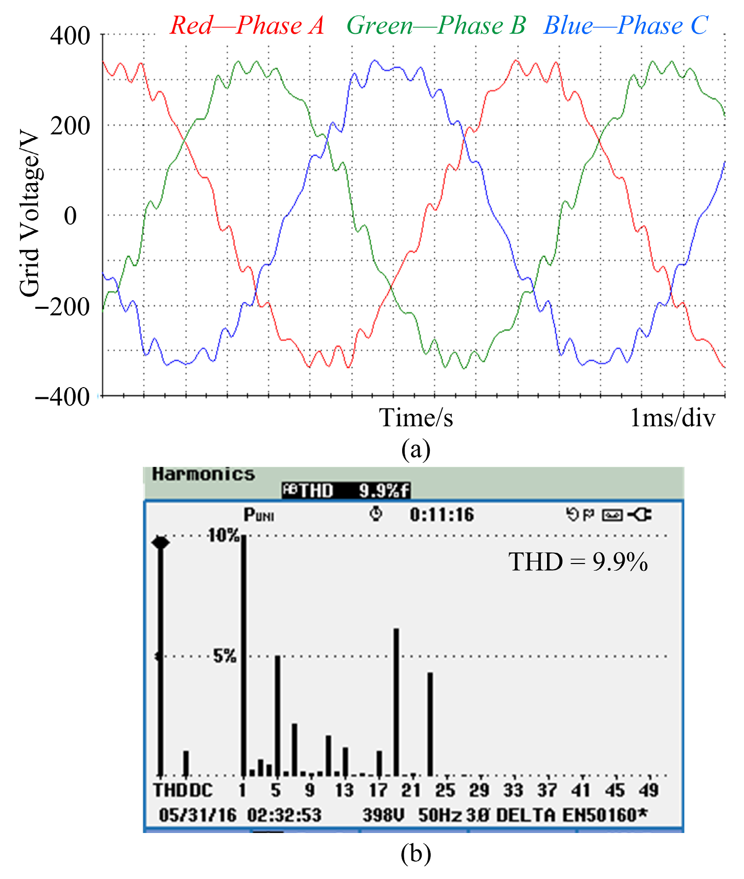
The controller performance is evaluated under a highly distorted grid condition, with the corresponding voltage waveform and frequency spectrum depicted in Figure 16a,b, respectively. The grid voltage is characterized by multiple harmonics, notably extending up to the 23rd order. This is a critical test case, as these harmonic frequencies lie above the resonance frequency of the LCL-filter.
Due to the proximity of the 19th- and 23rd-order harmonics to the LCL-filter resonance frequency, the conventional controller cannot provide adequate compensation. Consequently, the grid current contains significant high-order harmonic content, as shown in Figure 17. The total current THD is maintained at a relatively low level of 2.1%, as low-order harmonics are well compensated. In comparison, the proposed design strategy achieves satisfactory elimination of these high-order current harmonics, even when the harmonic voltage frequencies exceed the LCL-filter resonance frequency.
To evaluate the performance and robustness of the proposed controller design, experiments were carried out under varying grid impedance conditions. Figure 18 shows the grid current and its spectrum when all harmonics are compensated under two grid impedance values: Lg = 0 and Lg = 8 mH. As shown, compensation for the 19th- and 23rd-order harmonics yields a sinusoidal grid current. The corresponding THD values drop to 1.6% for Lg = 0 and 1.4% for Lg = 8 mH, respectively.
As illustrated in Figure 18b, the system remains stable even when the grid impedance increases from 0 to 8 mH, demonstrating strong robustness against wide-range grid impedance variations. It is particularly noteworthy that the LCL-filter resonance frequency in this case is as low as 800 Hz, which is well below the frequencies of the compensated 17th (850 Hz), 19th (950 Hz), and 23rd (1150 Hz) harmonics, further highlighting the effectiveness of the proposed method under challenging conditions.
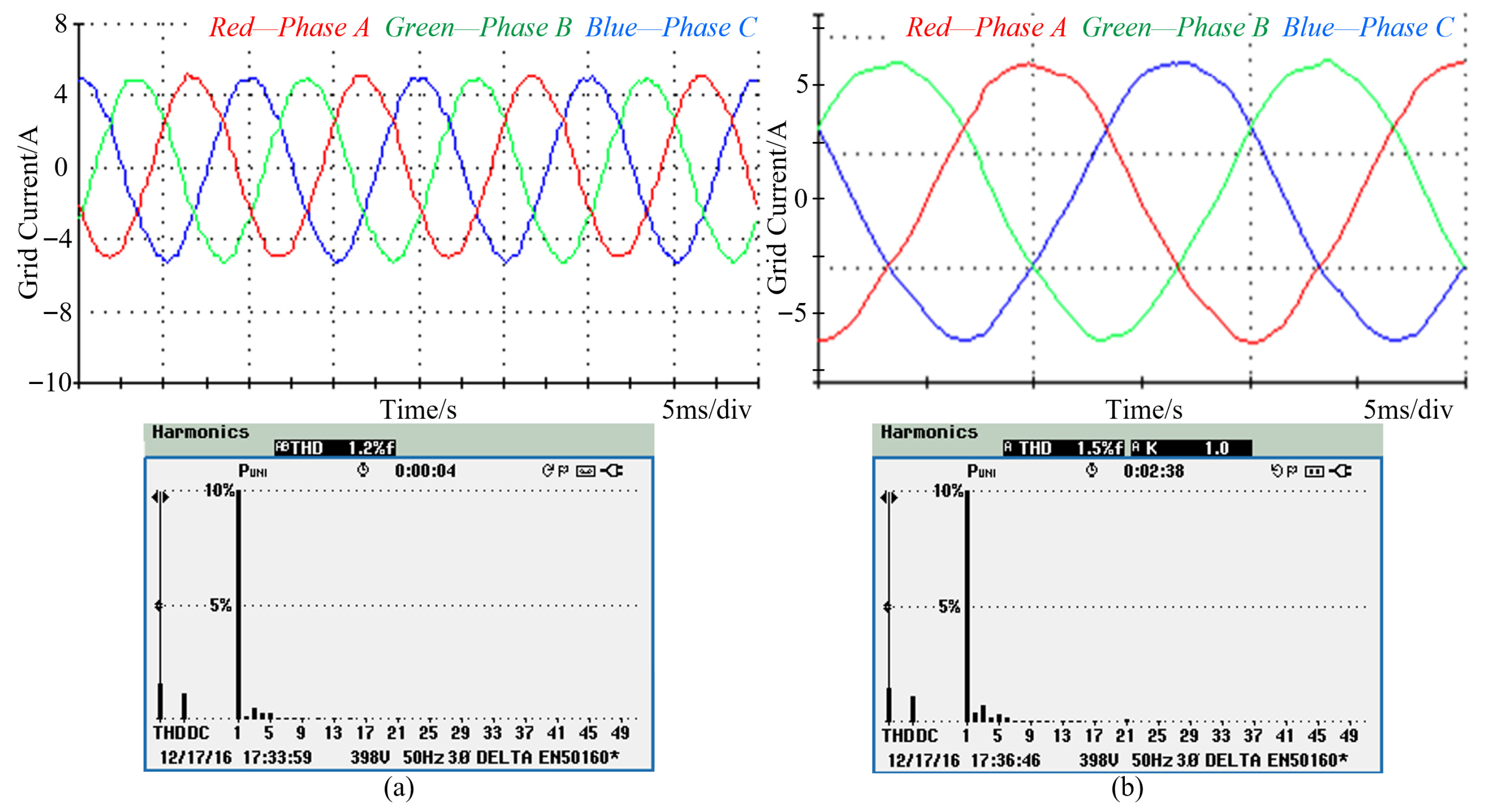
Moreover, to evaluate the harmonic mitigation performance under conditions where the harmonic frequency is lower than the filter resonance frequency, a comparative analysis between the conventional and the proposed phase-leading angle strategy is provided in Figure 19. Note that in this scenario, the 19th- and 23rd-order voltage harmonics are removed. As can be seen, the conventional method achieves a lower grid current THD of 1.2%, compared to 1.5% for the proposed method. This difference occurs because the conventional compensation angle closely matches the converter phase lag. However, the crucial advantage of the proposed strategy lies in its ability to effectively compensate for harmonics with frequencies higher than the filter resonance frequency, as demonstrated in Figure 18.
The dynamic performance of the system was assessed by applying a current reference step from 3 A to 6 A. As shown in Figure 20, the grid current reaches steady state within about one cycle.
Furthermore, the influence of compensation angle φc23 on system stability is also assessed by conducting another experiment regarding φc23 step changes. The resulting grid current waveforms are shown in Figure 21. As expected, grid current oscillations occur after φc23 decreases from 4.6 to 2.5, confirming the theoretical prediction that this setting leads to an unstable system.
5. Conclusions

This paper proposes a robust controller design strategy for grid-connected converters with LCL-filters, aimed at enhancing high-order harmonic compensation capability under wide-range grid impedance variations. This study establishes that the resonant controller can provide phase compensation up to 2π. By coordinating the system damping ratio with the phase leading angle offered by the resonant controller, the center frequency of the resonant controller can be tuned above the LCL-filter resonance frequency. This allows for flexible placement of the filter resonance frequency without compromising its performance in mitigating high-order harmonics. Moreover, the phase leading angle is optimized through a dual-objective approach that minimizes the sensitivity function while maximizing system robustness. As a result, harmonic compensation is effectively extended beyond the LCL-filter resonance frequency, even under significant grid impedance variations. Experimental validation under two distinct grid impedance conditions—using a resonant controller with a center frequency above the LCL-filter resonance frequency—confirms the theoretical analysis.

Author Contributions

Conceptualization, X.Z. and C.X.; methodology, X.Z.; software, X.Z.; validation, X.Z.; formal analysis, X.Z.; investigation, X.Z.; resources, X.W.; data curation, X.Z.; writing—original draft preparation, X.Z.; writing—review and editing, C.X., J.M.G. and X.W.; supervision, C.X., J.M.G. and X.W.; project administration, J.M.G.; funding acquisition, J.M.G. and X.Z. All authors have read and agreed to the published version of the manuscript.

Funding

This research was supported by the National Natural Science Foundation of China, grant number 52107208.

Data Availability Statement

Data is contained within the article.

Conflicts of Interest

The authors declare no conflict of interest.

References

  1. Guerrero, J.; Chandorkar, M.; Lee, T.; Loh, P. Advanced Control Architectures for Intelligent Microgrids—Part I: Decentralized and Hierarchical Control. IEEE Trans. Ind. Electron. 2013, 60, 1254–1262. [Google Scholar] [CrossRef]
  2. Espina, E.; Llanos, J.; Burgos-Mellado, C.; Cardenas-Dobson, R.; Martınez-Gomez, M.; Saez, D. Distributed control strategies for microgrids: An overview. IEEE Access 2020, 8, 193412–193448. [Google Scholar] [CrossRef]
  3. Sun, Q.; Zhou, J.; Guerrero, J.; Zhang, H. Hybrid Three-Phase/Single-Phase Microgrid Architecture with Power Management Capabilities. IEEE Trans. Power Electron. 2015, 30, 5964–5977. [Google Scholar] [CrossRef]
  4. Liserre, M.; Blaabjerg, F.; Hansen, S. Design and control of an LCL-filter-based three-phase active rectifier. IEEE Trans. Ind. Appl. 2005, 41, 1281–1291. [Google Scholar] [CrossRef]
  5. Twining, E.; Holmes, D. Grid Current Regulation of a Three-Phase Voltage Source Inverter with an LCL Input Filter. IEEE Trans. Power Electron. 2003, 18, 888–895. [Google Scholar] [CrossRef]
  6. Wang, C.; Pan, D.; Wang, X.; He, Y.; Zhang, H.; Ruan, X.; Chen, X. A General Graphical Method for Filter-Based Active Damping: Evaluation, Exploration and Design. IEEE J. Emerg. Sel. Topics Power Electron. 2023, 11, 2683–2696. [Google Scholar] [CrossRef]
  7. He, S.; Zhou, D.; Wang, X.; Blaabjerg, F. Passivity-Based Multisampled Converter-Side Current Control of LCL-Filtered VSCs. IEEE Trans. Power Electron. 2022, 37, 13848–13860. [Google Scholar] [CrossRef]
  8. Peña-Alzola, R.; Liserre, M.; Blaabjerg, F.; Sebastián, R.; Dannehl, J.; Fuchs, F. Analysis of the Passive Damping Losses in LCL-Filter-Based Grid Converters. IEEE Trans. Power Electron. 2013, 28, 2642–2646. [Google Scholar] [CrossRef]
  9. Li, S.; Lin, H. A Capacitor-Current-Feedback Positive Active Damping Control Strategy for LCL-Type Grid-Connected Inverter to Achieve High Robustness. IEEE Trans. Power Electron. 2022, 37, 6462–6474. [Google Scholar] [CrossRef]
  10. Zhang, H.; Wang, X.; He, Y.; Pan, D.; Ruan, X. A Compensation Method to Eliminate the Impact of Time Delay on Capacitor-Current Active Damping. IEEE Trans. Ind. Electron. 2022, 69, 7512–7516. [Google Scholar] [CrossRef]
  11. Pan, D.; Ruan, X.; Bao, C.; Wang, W. Capacitor-Current-Feedback Active Damping with Reduced Computation Delay for Improving Robustness of LCL-Type Grid-Connected Inverter. IEEE Trans. Power Electron. 2014, 29, 3414–3427. [Google Scholar] [CrossRef]
  12. Wang, J.; Yan, J.; Jiang, L.; Zou, J. Delay-Dependent Stability of Single-Loop Controlled Grid-Connected Inverters with LCL Filters. IEEE Trans. Power Electron. 2016, 31, 743–757. [Google Scholar] [CrossRef]
  13. Petric, I.; Mattavelli, P.; Buso, S. Passivation of Grid-Following VSCs: A Comparison Between Active Damping and Multi-Sampled PWM. IEEE Trans. Power Electron. 2022, 37, 13205–13216. [Google Scholar] [CrossRef]
  14. Stojić, Đ.; Šekara, T. Digital Resonant Current Controller for LCL-Filtered Inverter Based on Modified Current Sampling and Delay Modeling. IEEE J. Emerg. Sel. Top. Power Electron. 2022, 10, 7109–7119. [Google Scholar] [CrossRef]
  15. Harnefors, L.; Yepes, A.; Vidal, A.; Doval-Gandoy, J. Passivity-Based Stabilization of Resonant Current Controllers with Consideration of Time Delay. IEEE Trans. Power Electron. 2014, 29, 6260–6263. [Google Scholar] [CrossRef]
  16. Wang, X.; Blaabjerg, F.; Loh, P. Virtual RC Damping of LCL-Filtered Voltage Source Converters with Extended Selective Harmonic Compensation. IEEE Trans. Power Electron. 2015, 30, 4726–4737. [Google Scholar] [CrossRef]
  17. Zhang, Y.; Yang, X.; Zhang, Z. High-Efficiency Broadband Electroacoustic Energy Conversion Using Non-Foster-Inspired Circuit and Adaptively Switched Capacitor. IEEE Trans. Ind. Electron. 2025, 72, 9520–9531. [Google Scholar] [CrossRef]
  18. Tang, Y.; Loh, P.; Wang, P.; Choo, F.; Gao, F.; Blaabjerg, F. Generalized Design of High Performance Shunt Active Power Filter with Output LCL Filter. IEEE Trans. Ind. Electron. 2012, 59, 1443–1452. [Google Scholar] [CrossRef]
  19. Liu, Q.; Peng, L.; Kang, Y.; Tang, S.; Wu, D.; Qi, Y. A Novel Design and Optimization Method of an LCL Filter for a Shunt Active Power Filter. IEEE Trans. Ind. Electron. 2014, 61, 4000–4010. [Google Scholar] [CrossRef]
  20. Zhao, Q.; Zhang, H.; Xia, Y.; Chen, Q.; Ye, Y. Equivalence Relation Analysis and Design of Repetitive Controllers and Multiple Quasi-Resonant Controllers for Single-Phase Inverters. IEEE J. Emerg. Sel. Top. Power Electron. 2025, 13, 3338–3349. [Google Scholar] [CrossRef]
  21. Ye, J.; Huang, S.; Huang, Y.; Hu, Y.; Zhang, C.; Xu, J. A New Parameter Tuning Method for Generalized Multiresonant Current Controllers in Grid-Connected Inverters. IEEE Trans. Power Electron. 2024, 39, 10962–10975. [Google Scholar] [CrossRef]
  22. Yan, Y.; Lei, J.; Liu, B.; Xiang, X.; Li, C.; Li, C. Proportional Resonant Control with Phase Correction for Stability and Dynamics Enhancement Under Low Carrier Ratio Conditions. IEEE Trans. Power Electron. 2023, 38, 8597–8611. [Google Scholar] [CrossRef]
  23. Rockhill, A.; Liserre, M.; Teodorescu, R.; Rodriguez, P. Grid-Filter Design for a Multimegawatt Medium-Voltage Voltage-Source Inverter. IEEE Trans. Ind. Electron. 2011, 58, 1205–1217. [Google Scholar] [CrossRef]
  24. Zhao, X.; Kang, Z.; Wu, X.; Li, W.; Wu, X.; Xie, C. A Robust Design Strategy for Resonant Controllers Tuned Beyond the LCL filter Resonance Frequency. In Proceedings of the 2019 IEEE Applied Power Electronics Conference and Exposition (APEC), Anaheim, CA, USA, 17–21 March 2019; pp. 3051–3055. [Google Scholar]
  25. Holmes, D.; Lipo, T.; McGrath, B.; Kong, W. Optimized Design of Stationary Frame Three Phase AC Current Regulators. IEEE Trans. Power Electron. 2009, 24, 2417–2426. [Google Scholar] [CrossRef]
  26. Bojoi, R.; Griva, G.; Bostan, V.; Guerriero, M.; Farina, F.; Profumo, F. Current control strategy for power conditioners using sinusoidal signal integrators in synchronous reference frame. IEEE Trans. Power Electron. 2005, 20, 1402–1412. [Google Scholar] [CrossRef]
  27. Haro-Larrode, M.; Eguia, P.; Santos-Mugica, M. Analysis of voltage dynamics within current control time-scale in a VSC connected to a weak AC grid via series compensated AC line. Electr. Power Syst. Res. 2024, 229, 110189. [Google Scholar] [CrossRef]
  28. Yepes, A.; Freijedo, F.; Lopez, O.; Doval-Gandoy, J. Analysis and Design of Resonant Current Controllers for Voltage-Source Converters by Means of Nyquist Diagrams and Sensitivity Function. IEEE Trans. Ind. Electron. 2011, 58, 5231–5250. [Google Scholar] [CrossRef]
  29. Franklin, G.; Powell, G.; Workman, M. Digital Control of Dynamic Systems; Addison-Wesley: Boston, MA, USA, 1997. [Google Scholar]
  30. IEC 61000-4-7:2002; Electromagnetic Compatibility (EMC)—Part 4-7: Testing and Measurement Techniques—General Guide on Harmonics and Interharmonics Measurements and Instrumentation, for Power Supply Systems and Equipment Connected Thereto. EMC: Hamburg, Germany.
  31. Xie, C.; Zhao, X.; Li, K.; Zou, J.; Guerrero, J. Multirate Resonant Controllers for Grid-Connected Inverters with Harmonic Compensation Function. IEEE Trans. Ind. Electron. 2019, 66, 8981–8991. [Google Scholar] [CrossRef]
Figure 1. Three-phase converter connected to the grid through an LCL-filter.
Electronics 14 03991 g001
Figure 2. Plant model.
Electronics 14 03991 g002
Figure 3. Bode plot of Gpa(s).
Electronics 14 03991 g003
Figure 4. Block diagram of the system.
Electronics 14 03991 g004
Figure 5. Relationship between ξ and φc at different harmonic frequencies.
Electronics 14 03991 g005
Figure 6. Analysis of resonant controllers. (a) PZ map and (b) Bode diagram.
Electronics 14 03991 g006
Figure 7. Discretized block diagram of the grid current control scheme.
Electronics 14 03991 g007
Figure 8. Nyquist diagram of the open-loop system (ξ = 0.1) with and without the 17th-order resonant controller.
Electronics 14 03991 g008
Figure 9. Maximum value of S(z) with different resonant controllers implemented.
Electronics 14 03991 g009
Figure 10. Nyquist diagram of Gol(z) with different phase leading angles.
Electronics 14 03991 g010
Figure 11. |S(z)|max as a function of φc. (a) Full diagram and (b) zoomed-in diagram.
Electronics 14 03991 g011
Figure 12. Nyquist diagram of Equation (13) with multiple resonant controllers under grid inductance variations. (a) Lg = 0 mH and (b) Lg = 8 mH.
Electronics 14 03991 g012
Figure 13. Absolute values of the system sensitivity function. (a) Lg = 0 mH and (b) Lg = 8 mH.
Electronics 14 03991 g013
Figure 14. Maximum value of |S(z)| as a function of Lg.
Electronics 14 03991 g014
Figure 15. Experimental platform.
Electronics 14 03991 g015
Figure 16. Grid voltage and its spectrum. (a) Grid voltage, and (b) grid voltage spectrum.
Electronics 14 03991 g016
Figure 17. Grid current and its spectrum without 19th- and 23rd-order harmonics compensated for. (a) Grid current, and (b) grid current spectrum.
Electronics 14 03991 g017
Figure 18. Grid current and its spectrum with 19th- and 23rd-order harmonics compensated for. (a) Lg = 0 mH and (b) Lg = 8 mH.
Electronics 14 03991 g018
Figure 19. Grid current and its spectrum with conventional and proposed strategy. (a) Conventional and (b) proposed.
Electronics 14 03991 g019
Figure 20. Grid current steps from 3 A to 6 A.
Electronics 14 03991 g020
Figure 21. Grid current with φc23 steps from 4.6 to 2.5.
Electronics 14 03991 g021
Table 1. Parameters of power stage.
DescriptionSymbolValue
Nominal VoltageV230 V
Nominal Frequencyωf314 rad/s
DC VoltageVDC650 V
LCL-filter Resonance Frequencyfres1.02 kHz
Switching Frequencyfs10 kHz
Converter-Side InductorsL11.8 mH
Grid-Side InductorsL21.8 mH
CapacitorsCf27 µF
Parasite Resistor in Inductorsr0.05 Ω
Table 2. Groups of phase leading angles for resonant controller.
GroupcosφcsinφcZero of Gresd(s)
A (0 < φc < π/2)>0>0RHP
B (π/2 < φc < π)<0>0LHP
C (π < φc < 3π/2)<0<0RHP
D (3π/2 < φc < 2π)>0<0LHP
Table 3. Control system parameters.
ParametersSymbolValue
Proportional Gainkpi5.6
Time Constantτ0.036
Damping Ratioξ0.4
PLL Bandwidthfpll10
Resonant Controller Leading Angleφc52.1
φc72.27
φc112.75
φc133.0
φc173.59
φc193.89
φc234.60
Disclaimer/Publisher’s Note: The statements, opinions and data contained in all publications are solely those of the individual author(s) and contributor(s) and not of MDPI and/or the editor(s). MDPI and/or the editor(s) disclaim responsibility for any injury to people or property resulting from any ideas, methods, instructions or products referred to in the content.