Article

Quaternion-Based Velocity Scheduling for Robotic Systems

Department of Electrical Engineering, National Cheng Kung University, Tainan 701, Taiwan
*
Author to whom correspondence should be addressed.
Electronics 2025, 14(19), 3869; https://doi.org/10.3390/electronics14193869
Submission received: 25 August 2025 / Revised: 24 September 2025 / Accepted: 26 September 2025 / Published: 29 September 2025

Abstract

Finding the time-optimal parameterization of a given path subject to kinodynamic constraints is a critical topic in many robotic applications. However, designing a real-time motion planning algorithm for specified trajectories subject to physical constraints is challenging due to the high nonlinearity in robotic systems. Additionally, moving along a given path may include three types of motion—pure translation, pure orientation, and composite motion—which will further complicate finding the best solution in these applications. To cope with this difficulty, this paper proposes a complete, real-time quaternion-based velocity scheduling algorithm (QBVSA) that takes physical constraints such as joint velocity, joint acceleration, and joint torque into account. The proposed QBVSA is designed to efficiently handle various types of motion subject to physical constraints in real-time. The completeness of the proposed QBVSA is proved mathematically. By exploiting the idea of the initial velocity limit, the search for switching points—which is essential to the conventional numerical integration method—is not required in the proposed approach. Simulations and experiments are performed to validate the proposed motion planning approach.

1. Introduction

Motion/path planning is an important topic in robotics and automation [1,2]. Based on different kinds of constraints and application scenarios, researchers have proposed various path-planning approaches [3,4]. The decoupled planning method proposed in [5] has divided the motion planning problem into two sub-problems. The first sub-problem focuses on generating a trajectory based on geometric properties such as curvature and obstacle avoidance [6], while the second sub-problem aims at generating a feasible velocity profile that satisfies multiple constraints along the trajectory generated in the first sub-problem. This paper is dedicated to the second sub-problem, particularly the investigation of the time-optimal motion planning problem under kinematics constraints and dynamics constraints for a predefined path.
In order to achieve high productivity, the issue of time-optimal planning for a given path is crucial in many robotics and industrial manufacturing applications [7]. Therefore, scheduling velocity to be as high as possible in the Cartesian space is essential. However, when adopting a high desired velocity command, a deterioration in motion accuracy and smoothness may occur due to violations of the actuator’s physical constraints. In general, there are two types of physical constraints for industrial robots: kinematics constraints (joint velocity, joint acceleration, joint jerk, etc.) and dynamics constraints (joint torque, joint torque rate, etc.). Owing to the nonlinear kinematic transformation between the Cartesian space and the joint space, planning a time-optimal and feasible velocity profile under various constraints is a challenging task. The works in [8,9,10,11] formulate the time-optimal objective and physical constraints into an optimization problem to find an optimal path and velocity profiles. In [12,13,14], the via-points of a task path in the Cartesian space are converted into the joint space using inverse kinematics to obtain joint space commands. Recently, an approximation of a trapezoidal velocity profile (TVP) has been combined with an off-line trajectory planning method along specified linear/short paths in [15]. Instead of using TVP, the S-curve velocity profile is employed in [16] to generate a jerk-bounded velocity profile. The research in [17] solves the planning problem by means of a nonlinear filter. The concept of the online trajectory generator is extended in [18] by adding dynamics constraints. In addition to robotic systems, the velocity scheduling problem with nonlinear kinematic transformation also exists in CNC machining tools, especially five-axis machine tools [19,20].
Regarding the above-mentioned studies that focus on problems of velocity scheduling subject to physical constraints, few of them take the issue of orientation motion planning into consideration. Nevertheless, in industrial applications, tasks which involve only pure orientation motions are not uncommon. Namely, for the case that the end-effector does not have translation motion, it is possible that the actuator’s physical constraints may still be violated if motion planning of the orientation of the end-effector is not performed properly. Consequently, motion planning of the orientation subject to physical constraints should be conducted as well. Although the Euler angle representation is often used in SO(3), the robot’s singularity may excite the unexpected dynamics of the robot, and the gimbal lock problem may also occur. As a result, instead of using Euler angles, another representation of rotation—quaternion [21,22,23,24]—is very popular in practice. An online velocity-limited trajectory generator implemented by a low-pass filter and spherical linear interpolation in the quaternion space is proposed in [25]. In [26], a C4 smooth trapezoidal-like velocity profile and unit quaternion are applied in a 7-DOF lightweight robot for a V-REP simulation platform. In [27], after optimizing the differential vector of the tool posture along the path of the tool tip, the tool posture can be obtained by integrating the optimized differential vector. As discussed in [28,29,30], the algorithm of a virtual repulsive potential field is developed to plan a smooth posture trajectory of the robot’s end-effector. Despite the above works, robot motion planning subject to various constraints is still a challenging problem, since a real-time solution is essential in practice [31].
To schedule velocity in real-time tasks, the numerical integration method (NI-method) is adopted in [32,33]. Since the NI-method exploits the “bang-bang” structure, the computational cost is theoretically lower. The original version of the NI-method in [32,33] only considers torque constraints. However, velocity constraints should also be considered in real-world applications. The concept of a trap region on the plane of the path parameter and path parameter derivative is suggested in [34]. In addition, a feasible velocity planning algorithm subject to velocity and torque constraints is implemented in [35]. In [36], the parametric acceleration is approximated by a quadratic polynomial of parametric velocity, in which the desired velocity is scheduled by the bi-directional scanning method subject to joint velocity/acceleration constraints. Considering high-order constraints such as the jerk constraint, an iterative method for optimizing velocity profiles is proposed in [37]. In addition, the NI-method is also applied in redundantly actuated systems such as humanoid robots [38]. However, the algorithms used in these studies are not “complete” for velocity planning problems under second-order constraints. The term “complete algorithm” was coined in [39], which guarantees the finding of a feasible solution in finite time when one exists. The approach proposed in [40] searches for the “switch arc” on the speed limit curve and claims to be a complete algorithm for time-optimal velocity planning. The abovementioned approach was later extended in [41], which offers a trade-off mechanism and can be applied in both cruise trajectories and time-optimal trajectories. However, the case of pure orientation motion is not considered. In addition to the NI-method, popular motion planning approaches for robotic systems include sampling-based planners [42] and convex optimization-based approaches [43], etc. This paper focuses on the so-called kinodynamic planning problems, while most sampling-based planners focus on path planning problems rather than kinodynamic planning problems [42]. As pointed out in [43], the convex optimization-based approaches often lack mechanisms to determine infeasibility (i.e., not a complete algorithm).
To tackle the aforementioned velocity scheduling problems subject to physical constraints and multiple types of motions, this paper proposes a complete, near-time-optimal, real-time motion planning algorithm for 6-DOF industrial robots. In particular, by combining the initial velocity method, this paper copes with the problem of switching-point-searching encountered in NI-related methods. Moreover, a mathematical proof of completeness of the proposed solution search algorithm is also provided. The contributions of this paper are as follows:
(1)
A real-time, complete, near-time-optimal quaternion-based velocity planning approach is proposed, in which the computation time of the proposed approach is much shorter than that of the previous approach.
(2)
In the proposed approach, the initial velocity method is implemented before integrating maximum and minimum acceleration. Therefore, the NI-method can be employed directly without searching for switching points.
(3)
A mathematical proof for the completeness of the proposed solution search algorithm is given.
(4)
The relationship between the position of the task path and the orientation represented by the quaternion is constructed. The proposed approach is suitable for both translation motion planning and orientation motion planning—e.g., [1] or [2,3], or [4,5,6]. See the end of the document for further details on references.

2. Physical Constraints and Motion Type

For industrial robots, it is important to consider both kinematics constraints and dynamics constraints when performing velocity scheduling. To improve manufacturing efficiency, high velocity along the task path is desirable for most tasks so as to ensure time optimality. However, if a high velocity is adopted for the entire task path, kinematics constraints and dynamics constraints of the industrial robot may be violated due to the mapping between the joint space and the Cartesian space being highly nonlinear for most industrial robots. As a result, velocity profiles should be scheduled properly to satisfy multiple constraints and time optimality.

2.1. Kinematics Constraints

Suppose that the position and orientation of a robot moving along specific path C(s) can be represented by 3-dimensional vector P[x(s) y(s) z(s)] and O[α(s) β(s) γ(s)], where s 0 , s e n d is the arc length; x(s), y(s), z(s) and α(s), β(s), γ(s) represent the position and the Euler angles of the robot in the Cartesian space, respectively. The i t h joint angle qi(s) of a 6-DOF industrial robot can be obtained using inverse kinematics as follows:
q i ( s ) = M i ( x ( s ) , y ( s ) , z ( s ) , α ( s ) , β ( s ) , γ ( s ) )
where Mi represents the mapping (i.e., inverse kinematics) between the i t h joint angle qi(s) and P[x(s) y(s) z(s)], O[α(s) β(s) γ(s)] of the robot, where i = 1,2,…n, and n represents the degree of freedom (DOF).
Differentiating (1) with respect to time t will yield (2):
q ˙ i ( s ) = M s , i s ˙
where q ˙ i is the joint velocity of the ith axis, M s , i = d M i d s , and s ˙ is the tangential velocity in the Cartesian space.
Differentiating (2) with respect to t will yield (3):
q ¨ i = M s s , i s ˙ 2 + M s , i s ¨
where q ¨ i is the joint acceleration of the ith axis, M s s , i = d 2 M i d s 2 , and s ¨ represents the tangential acceleration in the Cartesian space.
In this paper, kinematics constraints on q ˙ i and q ¨ i are taken into consideration. Therefore, from (2) and (3), one will have the following two inequalities:
q ˙ i , max q ˙ i ( s ) = M s , i s ˙ q ˙ i , max
q ¨ i , max q ¨ i = M s s , i s ˙ 2 + M s , i s ¨ q ¨ i , max
where q ˙ i , max and q ¨ i , max are the maximum joint velocity and the maximum joint acceleration of the robot, respectively.

2.2. Dynamics Constraints

In general, the dynamic model of a robot can be expressed as
τ = I M q q ¨ + C q , q ˙ q ˙ + G q + F c s i g n q ˙ + F v q ˙
where τ : vector of joint torque; q ˙ , q ¨ are the vectors of joint velocity and joint acceleration, respectively; I M q n × n : inertia matrix of the robot; C q , q ˙ n × n : Coriolis and centrifugal matrix; G q n × 1 : vector of gravity torque; F c n × n : diagonal Coulomb friction matrix; F v n × n : diagonal viscous friction matrix.
In order to decouple q , s ˙ , and s ¨ , substituting (4) and (5) into (6) will lead to
τ i = j = 1 n d i j M s s , j s ˙ 2 + M s , j s ¨ + C i n d , i s ˙ 2 + G i + F c , i s i g n M s , i + F v , i M s , i s ˙
where d i j : entry on the ith row and the jth column of inertia matrix IM(q); F c , i : i t h entry on the diagonal of F c ; and F v , i : i t h entry on the diagonal of F v .
According to (7), one can derive the torque constraints for the robot as described by
τ i , max τ i = j = 1 n d i j M s s , j s ˙ 2 + M s , j s ¨ + C i n d , i s ˙ 2 + G i + F c , i s i g n M s , i + F v , i M s , i s ˙ τ i , max
where τ i , max is the maximum torque of the i t h joint.

2.3. Quaternion

The orientation of a robot can be described by quaternions, a 4-dimensional vector which is generally defined as
Q = Q 0 , Q 1 , Q 2 , Q 3 = Q 0 + Q 1 i + Q 2 j + Q 3 k
where Q0 is the real part of the quaternion Q, and Q1, Q2, Q3 are the imaginary parts of Q.
Orientation O r of a robot can be represented either by Euler angles or by quaternions; the relationship between Euler angles and quaternions can be expressed as
O r = Q = F EQ ( α , β , γ )
where F E Q is the transformation from the Euler angle to the quaternion. Suppose that the current orientation and the target orientation of a manipulator are represented by two unit quaternions, Q c and Q t . The spherical linear interpolation Q i n t (SLERP) [44,45] between the two orientations can be represented by
Q i n t = sin 1 u θ S L E R P sin θ S L E R P Q c + sin u θ S L E R P sin θ S L E R P Q t 0 u 1 θ S L E R P = cos 1 Q c Q t
where θ S L E R P is the total rotation angle between Q c and Q t , and u is the parameter of interpolation. When only the orientation of a robot is changed and the end-effector of the robot is held in the same position, the arc length of the moving trajectory is zero. To support this kind of task, the movement of orientation motion, which will be regarded as rotation angle s 2 , can be expressed as SLERP. Equation (11) can be rewritten as
Q i n t ( s 2 ) = sin θ S L E R P s 2 sin θ S L E R P Q c + sin s 2 sin θ S L E R P Q t s 2 = 0 , Δ s , 2 Δ s , , θ S L E R P
From Q c to Q t , the orientation value Q i n t ( s 2 ) of a robot can be calculated using (12).

2.4. Types of Motions

The motions of an industrial robot can be divided into three types: pure translation (PT), pure orientation (PO), and composite motion (TO, both the position and the orientation are changed during the motion). Most previous research has focused on PT and TO, while very few have addressed the case of PO. However, it is not unusual that the movement of a robot consists of PO motions in industrial applications. In this paper, the PO type of motion will also be discussed.
If an industrial robot executes a PT motion, the kinematic and dynamic constraints can be described by (2)~(8). In addition, arc length s in these equations can be expressed by the arc length of translation movement s1.
If an industrial robot performs a PO motion, s should be replaced by total rotation angle s2. In addition, s ˙ ,   s ¨ can be regarded as angular velocity ω and angular acceleration ω ˙ , respectively. Using (12), Q i n t ( s 2 ) will be calculated, and joint position q of the robot will also be calculated through inverse kinematics M(x(s2),y(s2),z(s2),α(s2), β(s2),γ(s2)). Hence, M s ,   M s s in (2)~(8) can be rewritten as M s 2 = d M d s 2 , M s 2 s 2 = d 2 M d s 2 2 .
If an industrial robot executes a TO motion, in order to synchronize the translation motion and the orientation motion, the ratio between the arc length of translation movement s1 and total rotation angle s2 should be kept as constant λ:
s 2 = λ s 1
With (13), the orientation of an industrial robot can be calculated by s1. Therefore, both the translation motion and the orientation motion can be computed by single parameter s1, and arc length s in (2)~(8) can be expressed in terms of s1.

3. Complete and Real-Time Motion Planning

In this paper, a Quaternion-Based Velocity Scheduling Algorithm (QBVSA) is proposed for industrial robots which can also be applied to CNC machine tools. A schematic diagram of the proposed QBVSA is shown in Figure 1. Given a specified task path and a robot model, in order to guarantee task time optimality and to satisfy kinematics constraints as well as dynamics constraints, velocity scheduling should be performed properly. The task path will be parameterized as having multiple intermediate task points (i.e., via points) in advance. These via points will be combined with the robot model, kinematics constraints and dynamics constraints, and then the parameters of kinematics and dynamics will be computed by using these data.
After calculating the kinematics and dynamics parameters, firstly the initial velocity limit will be generated by the proposed algorithm. Based on the initial velocity limit, the final velocity limit will be scheduled and updated by the bi-directional scanning method. The joint velocity, joint acceleration and joint torque of the robot will be constrained within the limit using the modified velocity profile. Depending on the final velocity limit, the time-domain velocity profile will be generated by the acceleration/deceleration interpolation module. Finally, the joint position command can be calculated using inverse kinematics.

3.1. Initial Velocity Limit

According to Sun et al. [19], all of the kinematics constraints and dynamics constraints can be classified into two types—neighbor independent (NBI) and neighbor dependent (NBD). In particular, the NBI constraint means that it only relates to s ˙ at a single interpolation point on the task path and does not become involved with derivatives of the velocity, e.g., tangential acceleration s ¨ and/or tangential jerk s . Compared with the NBI constraint, both the velocity and its derivatives will be involved in the calculation of the NBD constraint.
In this paper, the joint velocity is an NBI constraint, while the joint acceleration and the joint torque are NBD constraints. Due to the inherent properties of NBD constraints, it is difficult if not impossible to determine the velocity profile analytically subject to all constraints.
In order to decouple velocity and the derivative of velocity in (5) and (8), the initial velocity limit will first be determined. If s ˙ is kept unchanged at each interpolation point of the task path, the value of s ¨ in the NBD constraint will be zero. Therefore, (5) and (8) can be rewritten as (14) and (15):
q ¨ i , max q ¨ i = M s s , i s ˙ 2 q ¨ i , max
τ i , max τ i = j = 1 n d i j M s s , j s ˙ 2 + C i n d , i s ˙ 2 + G i + F c , i s i g n M s , i + F v , i M s , i s ˙ τ i , max
After decoupling s ˙ and s ¨ , joint acceleration and joint torque can be regarded as NBI constraints, since their values are only related to s ˙ . By combining (4), (14) and (15), initial velocity limit s ˙ i v l can be derived by (16):
s ˙ i v l = min q ˙ max , i M s , i , q ¨ max , i M s s , i , F Q ( τ max , i , M s , i , M s s , i , d i j , C i n d , i , F c , i , F v , i ) i = 1 , 2 , D O F
where F Q is the function for calculating the solution of s ˙ that satisfies the quadratic polynomial described by (15).
Instead of computing the maximum velocity curve in a way similar to how the conventional numerical integration method does, in the proposed QBVSA, the initial velocity limit will be determined first before performing velocity scheduling using the bi-directional scanning method. Under this upper limit of initial velocity s ˙ , kinematics constraints and dynamics constraints will not be violated at each interpolation point of the task path if the tangential acceleration is zero.

3.2. Bi-Directional Scanning Method

Using (16), the constraints on joint velocity, joint acceleration and joint torque are guaranteed to be satisfied under the condition of constant tangential velocity. However, to achieve highly efficient machining, performing acceleration/deceleration (Acc/Dec) with respect to tangential velocity is very common in the automated manufacturing industry. As a result, it is possible that kinematics constraints and dynamics constraints will be violated, since the tangential velocity is not a constant.
In this paper, after the initial velocity limit is calculated, the bi-directional scanning method is adopted to ensure that physical constraints will not be violated during Acc/Dec. Suppose that tangential acceleration s ¨ between two nearby task points on a parametric path is constant. Consequently, s ¨ = s ˙ 2 s ˙ o l d 2 2 Δ s , where s ˙ is the tangential velocity at the current task point, s ˙ o l d represents the tangential velocity of the last task point and Δ s is the arc length between the current task point and the previous task point. Now (5) and (8) can be rewritten as (17) and (18):
q ¨ i , max q ¨ i = M s s , i s ˙ 2 + M s , i s ˙ 2 s ˙ o l d 2 2 Δ s q ¨ i , max
τ i , max τ i = j = 1 n d i j M s s , j s ˙ 2 + M s , j s ˙ 2 s ˙ o l d 2 2 Δ s + C i n d , i s ˙ 2 + G i + F c , i s i g n M s , i + F v , i M s , i s ˙ τ i , max
Kinematics constraints and dynamics constraints will not be violated if the Acc/Dec zone of velocity control is obtained by satisfying (17) and (18). Due to the fact that s ˙ o l d , Δ s , and the values of the parameters of kinematics and dynamics such as M s , i , G i are known at each task point, (17) and (18) can be rewritten as a quadratic polynomial of s ˙ :
A i s ˙ 2 + B i s ˙ + C i ( s ˙ o l d ) > 0 i = 1 , 2 2 n , n = D O F
where A i ,   B i ,   C i are constant coefficients at each task point. During forward scanning and backward scanning, after solving every inequality at a specified task point, the upper bounds and lower bounds of s ˙ can be computed, and the solutions of forward and backward scanning at the k t h task point s ˙ f , k ,   s ˙ b , k can also be calculated by the minimum upper bound and initial velocity limit s ˙ u p , k ,   s ˙ i v l , k . After forward scanning and backward scanning are completed, one can obtain the final solution s ˙ b i , k = min ( s ˙ f , k , s ˙ b , k ) of s ˙ at the kth task point.
From (5) and (8) to (19), the inequalities of kinematics and dynamics are derived from a quadratic polynomial of s ˙ . By employing the initial velocity limit and the bi-directional scanning method, the near-time-optimal velocity profile can be scheduled from the starting point to the endpoint of the task path and none of the kinematics constraints and dynamics constraints will be violated. In addition, compared with the conventional numerical integration method, the process of searching for switching points can be omitted, since an s ˙ solution always exists during bi-directional scanning using the proposed method. The mathematical proof for the existence of an s ˙ solution will be given in the next section. The pseudo code of the proposed QBVSA is shown in Appendix A.

4. Completeness Proof of the Proposed QBVPA

This section will first briefly review the conventional numerical integration (NI) method, and the mathematical proof of the proposed method will be given subsequently.

4.1. Numerical Integration Method with Torque and Velocity Constraints

The time-optimal trajectory planning of robots based on physical constraints has long been a popular research topic. In order to achieve both highly efficient and accurate machining, the NI-method proposed in [32,33] considers torque constraints along the task path s 0 , s e n d . By parameterizing the task path, the parameters of the robot models can be obtained. Tangential acceleration s ¨ in the Cartesian space, which is limited by torque constraints, can be derived as follows:
α s , s ˙ s ¨ β s , s ˙
where α s , s ˙ and β s , s ˙ are the minimum tangential acceleration and the maximum tangential acceleration, respectively. In the original NI-method, maximum velocity curve MVC will be computed first:
M V C s = min s ˙ 0 α s , s ¨ = β s , s ¨ ,   s s 0 , s e
Based on the MVC profile (i.e., maximum s ˙ along the task path), the accelerating velocity profiles and decelerating velocity profiles are integrated in both forward and backward directions in the phase plane (s, s ˙ ) with β s , s ¨ and α s , s ¨ , respectively. Eventually, the final s ˙ profile is composed of MVC, acceleration profiles, and deceleration profiles. Since the integration is performed in both forward and backward directions, it is also called “bi-directional scanning”. However, the scanning may fail when the velocity constraints are taken into consideration. More detailed failure conditions are devised in [46] with a mathematical proof. In order to find a feasible solution, the key problem of this technique is the computation of switching points on MVC. This issue has attracted much attention in many previous studies [34,35,36,37,40,41], and several methods have been developed to determine the switching points and the final velocity profile.
Compared with the aforementioned approaches, instead of calculating MVC, the initial velocity limit is calculated first in the proposed approach. After transforming s ¨ into a quadratic form of s ˙ , the proposed bi-directional scanning method can be applied directly without further computation, thus ensuring that a feasible s ˙ will be generated. A detailed proof of the completeness of the proposed QBVSA will be given in the following subsection.

4.2. Mathematical Proof of Existence of Velocity Solution Obtained Using QBVSA

For each task point in the parametric task path, (17) and (18) can be combined as described by (22):
L i F 1 , i s ˙ + F 2 , i s ¨ = F 3 , i L i F 1 , i s ˙ = a i s ˙ 2 + b i s ˙ + c i , i = 1 , 2 , 3 , 2 n , n = D O F F 2 , i s ¨ = d i s ¨ = d i s ˙ 2 s ˙ o l d 2 2 Δ s = d i s ˙ 2 s ˙ o l d 2 F 3 , i = a i s ˙ 2 + b i s ˙ + c i + d i s ˙ 2 s ˙ o l d 2
where Li represents the constraints of joint acceleration or joint torque, while F 1 , i s ˙ and F 2 , i s ¨ are the functions of tangential velocity and tangential acceleration, respectively. Since the tangential acceleration is transformed into a quadratic form of s ˙ , F 2 , i s ¨ can also be viewed as F 2 , i s ˙ 2 , s ˙ o l d 2 . For the current task point, s ˙ o l d is the tangential velocity of the last task point which will be computed by the proposed QBVSA. a i , b i , c i , d i , which are composed of parameters of kinematics and dynamics, are the constant coefficients of quadratic inequalities of s ˙ .
Useful properties of the proposed QBVSA and detailed proofs about the completeness of the proposed QBVSA will be given as follows.
Property 1: Since this paper does not take into consideration cases such as singular points of the robot manipulators and discontinuous task paths, the values of the coefficients ai, bi, ci, di of the quadratic inequality (22) for s ˙ are finite for the entire task path. In addition, the value of s ˙ is also finite. Therefore, one can conclude that functions F1,i, F2,i and F3,i are Lipschitz continuous functions [47].
Property 2: In the proposed QBVSA, the initial velocity limit for each task point is computed using (16) first. During forward and backward scanning, s ˙ will be calculated only when the initial velocity limit for current task point s ˙ i v l ,   c is larger than s ˙ o l d . Otherwise, s ˙ will not be updated. The bi-directional scanning method computes s ˙ under the constraints of joint acceleration and joint torque based on the initial velocity limit. Therefore, in forward scanning, only the positive tangential acceleration zone is required to be considered. In addition, the negative tangential acceleration zone in forward scanning will become the positive acceleration zone during backward scanning. As a result, s ˙ will only be updated under the condition that s ˙ i v l ,   c > s ˙ o l d for both forward scanning and backward scanning.
Property 3: Constraint L i < F 3 , i s ˙ ε ε ,   s ¨ = 0 < L i will not be violated when s ˙ is almost zero and s ¨ is zero, where ε is a small positive real number.
Before the robot starts to move, s ˙ = 0 and s ¨ = 0. In this case, the torque constraint described by (15) only contains the terms related to gravity and static friction. The amount of joint torque exerted by the robot must be larger than these two terms so that the robot can start to move. Namely, the sum of the terms related to gravity and maximum static friction satisfies (15). Otherwise, (15) will be violated even before the robot starts to move. When the motor starts to move, s ˙ is initially very small (i.e., almost zero). In addition, the friction consists of Coulomb friction and viscous friction rather than static friction in this case. Since s ˙ is almost zero, viscous friction can be ignored. Namely, the value of F3,i is almost equal to the sum of the terms related to gravity and Coulomb friction. Note that Coulomb friction is smaller than the maximum static friction. As a result, Property 3 is reasonable.
Theorem 1.
During forward scanning and backward scanning, constraints   L i < F 3 , i s ˙ o l d < L i  will not be violated if  s ˙  for the current task point is equal to   s ˙ o l d .
Proof of Theorem 1.
According to (22), F 3 , i is comprised of F 1 , i and F 2 , i . Due to Property 2, when the current s ˙ is equal to s ˙ o l d , s ˙ will not be updated and the value of F1,i satisfies the torque constraint. Consequently, summing the values of F 1 , i and F 2 , i will lead to
L i < F 3 , i s ˙ o l d = F 1 , i s ˙ o l d + F 2 , i s ˙ o l d < L i .
This completes the proof of Theorem 1. □
Theorem 2.
For a given   s ˙ o l d , there always exists a positive velocity increment  Δ s ˙ i  such that joint constraints   L i F 3 , i s ˙ o l d + Δ s ˙ i L i  will not be violated.
Proof of Theorem 2.
For a Lipschitz continuous function F(x), it must satisfy the following inequality:
F x 1 F x 2 K x 1 x 2 F :  
where x1, x2 are subsets of and K is a positive real number.
According to Property 1, F(x) in (23) can be replaced by F 3 , i s ˙ . Therefore, one can derive (24) and (25) as follows:
F 3 , i s ˙ max , i F 3 , i s ˙ o l d K s ˙ max , i s ˙ o l d s ˙ max , i 0 , s ˙ i n i t i a l ,   c u r r e n t
F 3 , i s ˙ o l d + Δ s ˙ i F 3 , i s ˙ o l d K s ˙ o l d + Δ s ˙ i s ˙ o l d
where K is a positive real number; s ˙ max , i is the tangential velocity at the current task point that results in the absolute maximum value of constraints F 3 , i s ˙ within the initial velocity limit; namely, the value of F 3 , i s ˙ max , i must be either Li or −Li.
Suppose that
F 3 , i s ˙ max , i F 3 , i s ˙ o l d = δ
Choose
Δ s ˙ i = δ 2 K
where δ is a positive real number. From (24), (26), and (27), one can rewrite (25) as:
F 3 , i s ˙ o l d + Δ s ˙ i F 3 , i s ˙ o l d F 3 , i s ˙ max , i F 3 , i s ˙ o l d 2
To prove Theorem 2, (28) will be divided into the following two cases:
C 1 : F 3 , i s ˙ o l d + Δ s ˙ i F 3 , i s ˙ o l d C 2 : F 3 , i s ˙ o l d + Δ s ˙ i < F 3 , i s ˙ o l d
For case C1, (28) can be rewritten as
F 3 , i s ˙ o l d + Δ s ˙ i F 3 , i s ˙ o l d F 3 , i s ˙ max , i F 3 , i s ˙ o l d 2
Step 1-1: Prove F 3 , i s ˙ o l d + Δ s ˙ i L i in case C1.
To discuss the relationship between F 3 , i s ˙ o l d + Δ s ˙ i and L i , for simplification, the value of F 3 , i s ˙ max , i is denoted as L i * :
i f   F 3 , i s ˙ < L i : L i * = max F 3 , i s ˙ e l s e : L i * = L i s ˙ s ˙ o l d , s ˙ i v l , c
Since L i * is the positive maximum value resulting from s ˙ max , i in the range between s ˙ o l d and s ˙ i v l , c , the value of L i * must thus be larger than F 3 , i s ˙ o l d . As a result, (29) can be rewritten as
F 3 , i s ˙ o l d + Δ s ˙ i F 3 , i s ˙ o l d F 3 , i s ˙ max , i F 3 , i s ˙ o l d 2
By adding F 3 , i s ˙ o l d to both sides of (31) and also replacing F 3 , i s ˙ max with L i * , (31) becomes
F 3 , i s ˙ o l d + Δ s ˙ i L i * + F 3 , i s ˙ o l d 2 < L i
Since both values of L i * and F 3 , i s ˙ o l d are smaller than Li, Li must thus be larger than the arithmetic mean of L i * and F 3 , i s ˙ o l d .
Step 1-2: Prove L i F 3 , i s ˙ o l d + Δ s ˙ i in case C1.
In case C1, F 3 , i s ˙ o l d + Δ s ˙ i F 3 , i s ˙ o l d , and Theorem 1, one will have
F 3 , i s ˙ o l d + Δ s ˙ i F 3 , i s ˙ o l d > L i
With (32) and (33), one can conclude that Theorem 2 is valid for case C1. Secondly, in case C2, (28) can be rewritten as
F 3 , i s ˙ o l d F 3 , i s ˙ o l d + Δ s ˙ i F 3 , i s ˙ max , i F 3 , i s ˙ o l d 2
Step 2-1: Prove F 3 , i s ˙ o l d + Δ s ˙ i L i in case C2.
To discuss the relationship between −Li and F 3 , i s ˙ o l d + Δ s ˙ i , the value of F 3 , i s ˙ max , i is denoted as L i * :
i f   F 3 , i s ˙ > L i : L i * = min F 3 , i s ˙ e l s e : L i * = L i s ˙ s ˙ o l d , s ˙ i v l , c
Compared with (30), L i * in (35) is the negative minimum value resulting from s ˙ max , i in the range between s ˙ o l d and s ˙ i v l , c so that the value of L i * must be smaller than F 3 , i s ˙ o l d . As a result, (34) can be rewritten as
F 3 , i s ˙ o l d + F 3 , i s ˙ max , i 2 F 3 , i s ˙ o l d + Δ s ˙ i
With (35) and (36), one will have
L i < F 3 , i s ˙ o l d + L i * 2 F 3 , i s ˙ o l d + Δ s ˙ i
Since both the values of L i * and F 3 , i s ˙ o l d are larger than L i , L i must thus be smaller than the arithmetical mean of L i * and F 3 , i s ˙ o l d .
Step 2-2: Prove F 3 , i s ˙ o l d + Δ s ˙ i L i in case C2.
In case C2, F 3 , i s ˙ o l d + Δ s ˙ i < F 3 , i s ˙ o l d , and Theorem 1, one will have
F 3 , i s ˙ o l d + Δ s ˙ i < F 3 , i s ˙ o l d < L i
With (37) and (38), one can conclude that Theorem 2 is also valid for case C2. This completes the proof of Theorem 2. □
Theorem 3.
Under the joint acceleration constraints and the joint torque constraints, the proposed approach which implements bi-directional scanning based on the initial velocity limit can find a feasible solution for path-constrained trajectory planning, if one exists.
Proof of Theorem 3.
By Theorems 1 and 2, there always exists a positive velocity increment Δ s ˙ i such that the joint constraints will not be violated. As a result, for i = 1 , 2 , 2 n ,   n = D O F , there exists an upper velocity limit s ˙ b i , i (where s ˙ b i , i > s ˙ o l d ) such that F 3 , i s ˙ b i , i will not exceed the constraints. Namely, a feasible velocity s ˙ B I = min s ˙ b i , i for i = 1 , 2 , 2 n can be found by the proposed approach under the constraints of joint acceleration and joint torque. In addition, s ˙ B I is in the range between s ˙ o l d and s ˙ i v l , c . This completes the proof of Theorem 3. □
According to Theorems 1–3, the completeness of the proposed QBVSA which combines the initial velocity limit and the bi-directional scanning method is proved mathematically. Consequently, a near-time-optimal feasible s ˙ can be calculated directly in real time without extra computation. Compared with the conventional NI method or other related methods, the proposed approach is more general and highly computationally efficient.

5. Simulation and Experiment Results

In order to assess the performance of the proposed velocity scheduling approach, several simulations and experiments were performed on a 6-DOF industrial robot (shown in Figure 1) which executes tasks along a pure orientation (PO) motion and a composite (TO) motion. In this paper, joint velocity constraints, joint acceleration constraints, and joint torque constraints are taken into consideration. The limits of these constraints for each joint of the Delta DRV70L 6-DOF industrial robot used in this paper are shown in Table 1.
In the simulation, the scheduled velocity obtained from the proposed QBVSA is substituted into (2), (3), and (7) so that the pre-interpolation simulation results of joint velocity, joint acceleration, and joint torque can be calculated. Consequently, in the experiments, the industrial robot performs a TO motion based on the scheduled velocity.

5.1. Simulation Results on Pure Orientation Motion

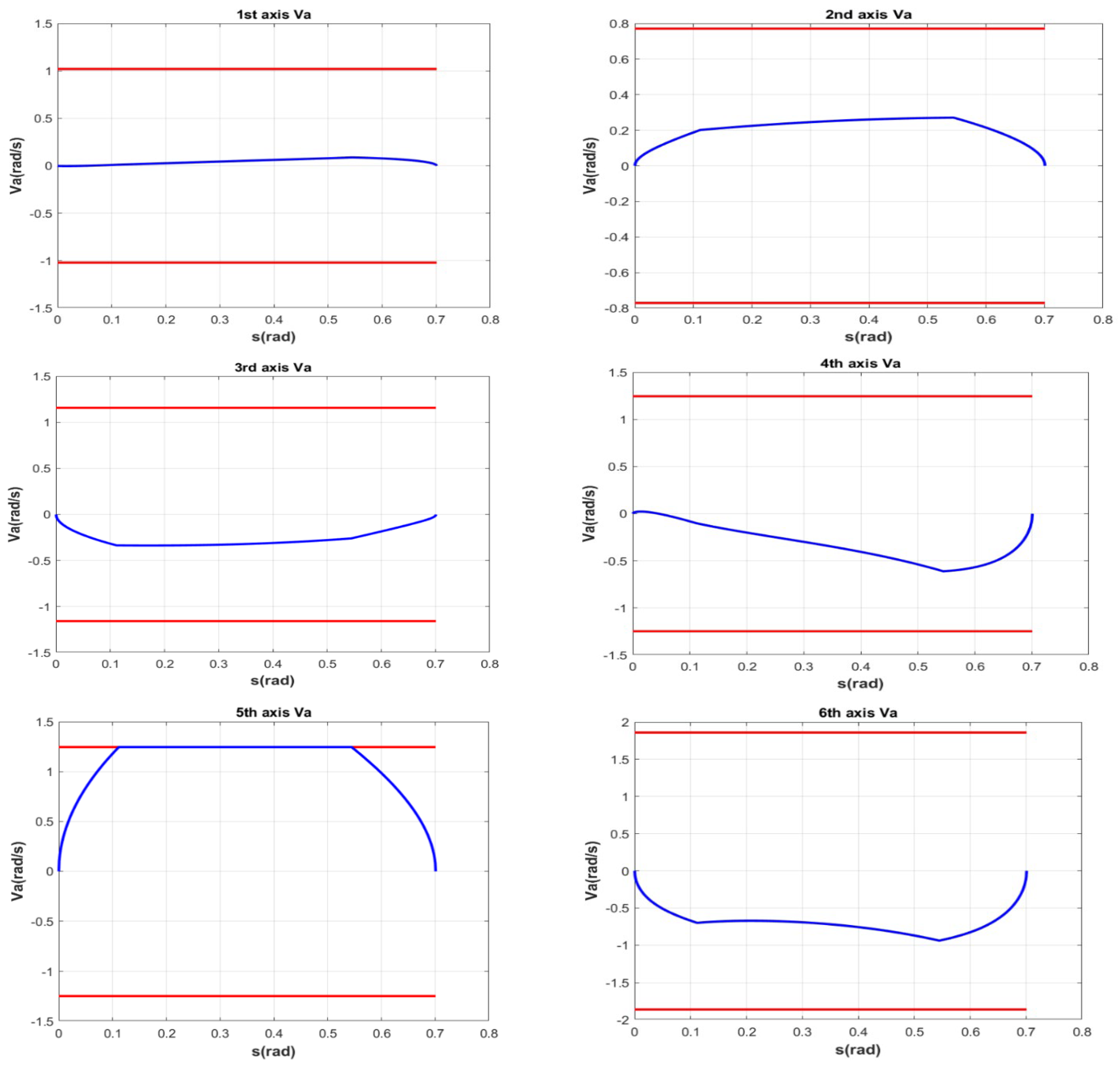
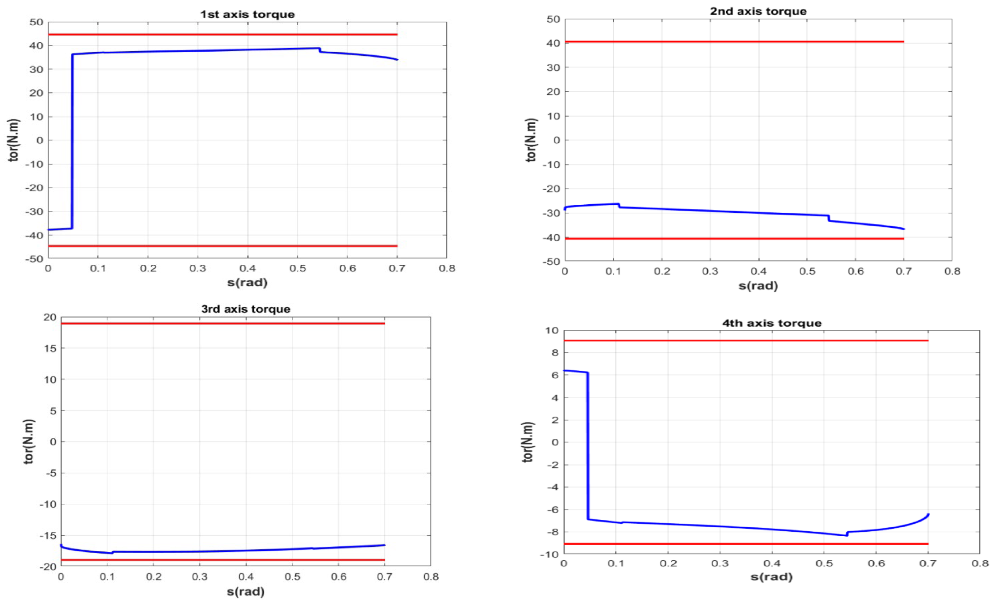
The parameters of the PO motion used in this simulation are shown in Table 2. Since the starting point and the end point for the case of pure orientation are the same, the length of the translation motion is zero. As shown in Table 2, the orientations (defined by the Euler angle) of the starting point and the end point are different. In addition, angular velocity ω is scheduled during the PO motion by the proposed method. Figure 2 shows that forward scanning curves β1, β2 and backward scanning curve α1 are directly generated by the proposed approach under all physical constraints without extra computation. Furthermore, the angular velocity is clamped by the initial angular velocity limit in the region from p 1 s 2 = 0.11 to p 2 s 2 = 0.54 . Finally, time-optimal angular velocity profile β 1 p 1 p 2 α 1 is connected from starting point s 2 , s t a r t s ˙ 2 , s t a r t = 0 to end point s 2 , e n d s ˙ 2 , e n d = 0 of the PO motion using the proposed approach. As shown in Figure 3, Figure 4 and Figure 5, the joint velocities, joint accelerations and joint torques are all kept within the limit. Moreover, besides the velocity of the 5 t h joint reaching the maximum limit from p1 to p2, the accelerations of the 5 t h joint in the interval of β1 and α1 are equal to the upper bound and the lower bound, respectively. These simulation results show that the proposed velocity scheduling approach can indeed be applied to the case of PO motion.

5.2. Simulation Results on Composite Motion

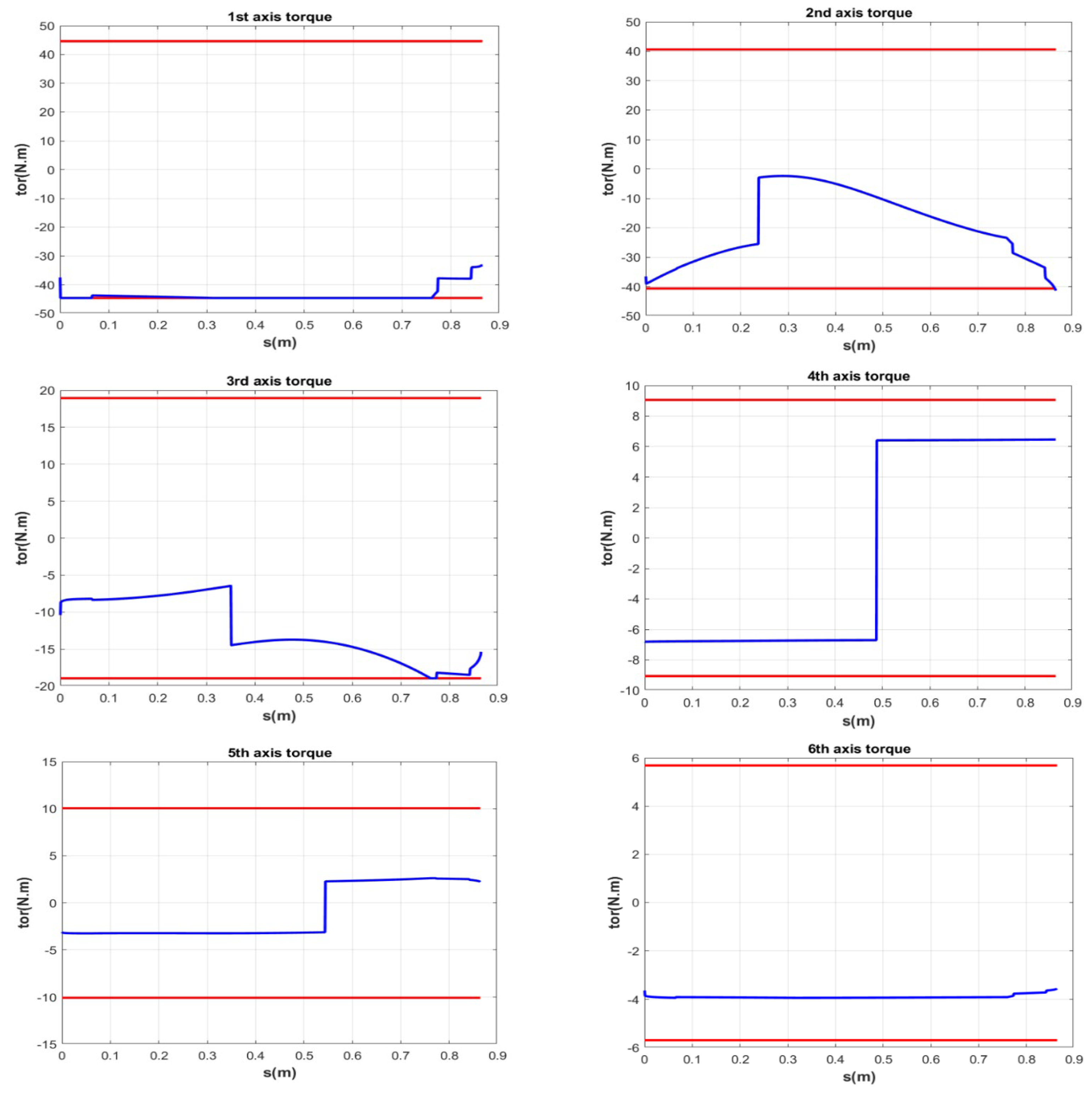
The TO motion used in this simulation is shown in Table 3. Unlike the PO motion, both the translation motion and orientation motion are included in the TO motion. In particular, the length of translation and the rotation angle are 0.86 m and 0.13 rad, respectively. In Figure 6, forward scanning curves β1, β2 and backward scanning curve α1 are produced by the proposed QBVSA. In addition, the velocity is clamped by the initial velocity limit in two regions, including p 1 s 1 = 0.066 to p 2 s 1 = 0.32 , and p 3 s 1 = 0.77 to p 4 s 1 = 0.84 . For the TO motion, final profile β 1 p 1 p 2 β 2 p 3 p 4 α 1 of the velocity is connected from starting point s 1 , s t a r t to end point s 1 , e n d under the proposed method. Figure 7, Figure 8 and Figure 9 show that the joint velocities, joint accelerations, and joint torques are all kept within the limits. In addition, the acceleration of the 3 r d axis and the torques of the 1 s t and 3 r d axes also reach the limits. It is worth noting that the computation time for using the proposed QBVSA to generate the TO motion was 5.63 ms, which is much shorter than the computation time (more than 30 ms) needed for the approach developed in [40].

5.3. Experimental Results

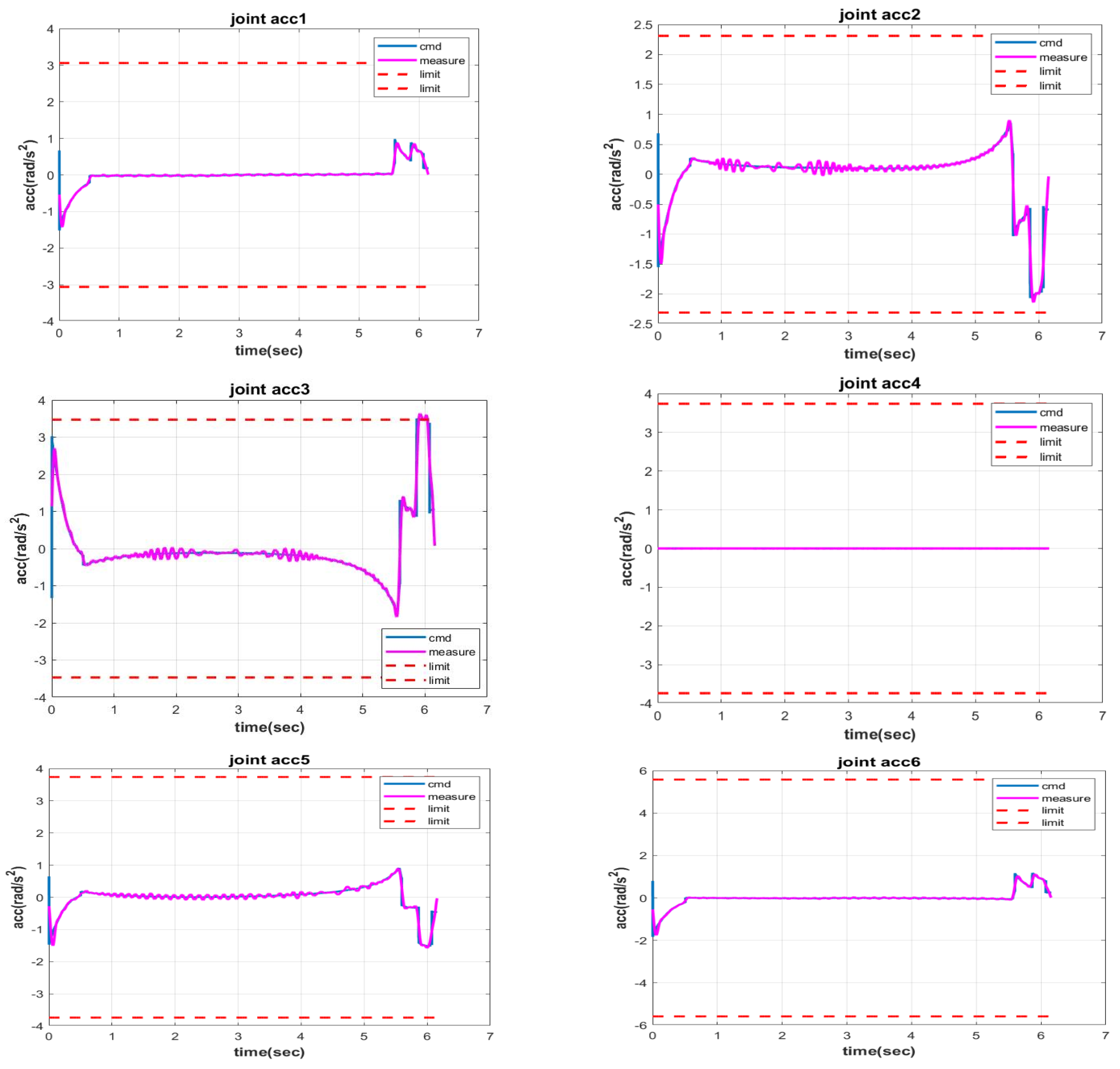
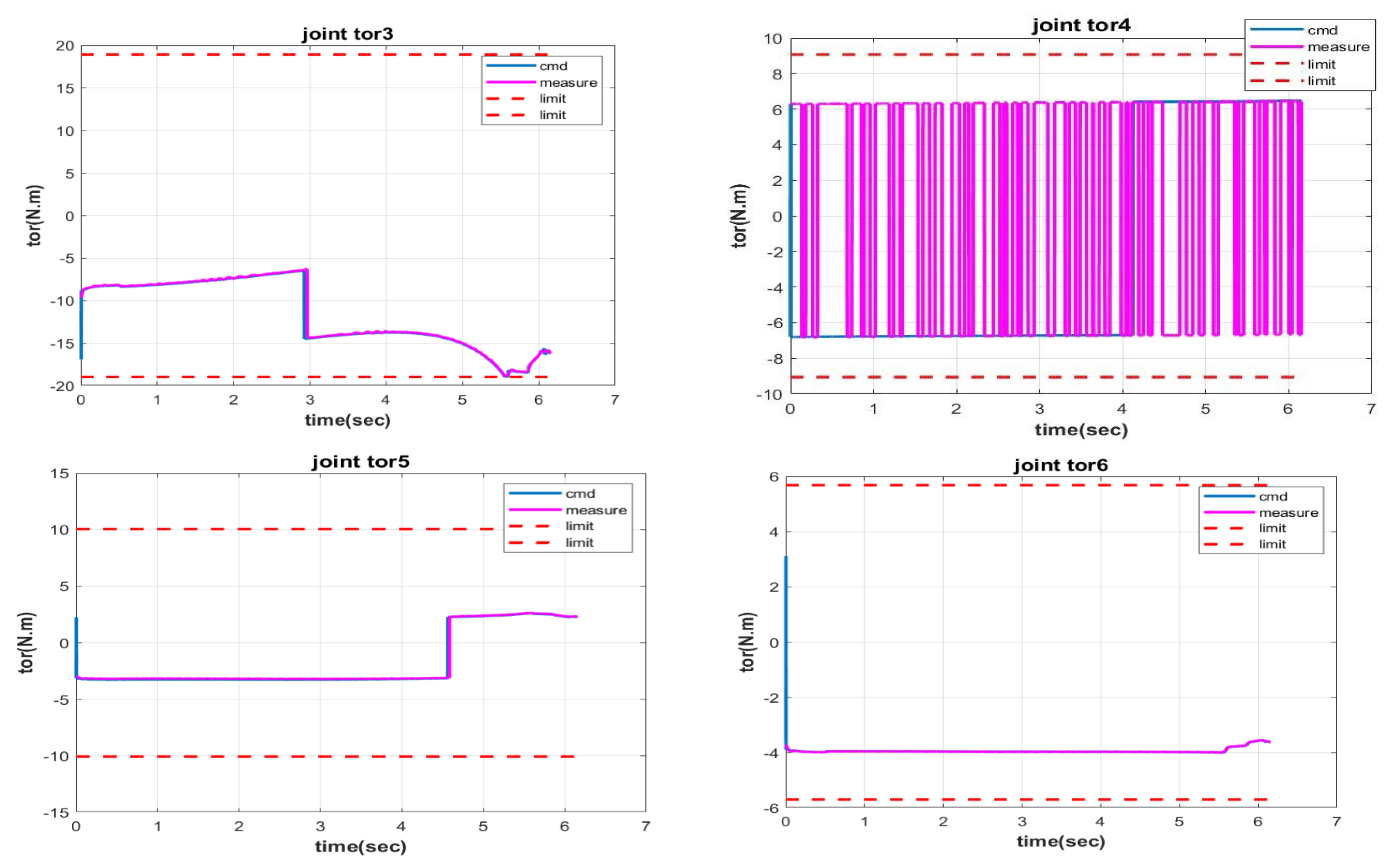
Figure 10 shows the schematic diagram of the experimental system. The experiment was conducted on the Delta DRV70L 6-DOF industrial robot. The sampling period was set as 0.001 s, and a PC-based control architecture was adopted. With the proposed QBVSA, the previously mentioned TO motion was executed on the industrial manipulator and the constraints are the same as those in Table 1. Under the constraints of joint velocity, joint acceleration and joint torque, the results of tangential velocity scheduling and tangential acceleration scheduling in the time domain of TO motion are shown in Figure 11, respectively. Experimental results are shown in Figure 12, Figure 13 and Figure 14. By performing numerical differentiation with respect to the encoder data, one can obtain the joint velocities and joint accelerations. Due to tracking error and measurement noise, there is some deviation between the second-order derivative of the encoder data and the acceleration command (Figure 13). In addition, because of the zero movement of the 4 t h joint and the viscous friction, the measured torque of the 4 t h joint shown in Figure 14 switches between −6.81 Nm and 6.30 Nm.
Despite the existence of tracking error and measurement noise, by using the proposed approach, near-time-optimal velocity profiles can be generated directly and the values of the joint velocities, joint accelerations and joint torques are all successfully bounded in the constraints for the TO motion. The computational time for the QBVSA applied to the time-optimal TO motion is 5.263 ms, making it suitable for industrial real-time applications and significantly faster than the results reported in [40], which exceed 30 ms. Both simulation and experimental results validate our proposed approach, confirming its ability to achieve near-time-optimal results while satisfying all physical constraints for both translational and rotational motions in real-time.

6. Conclusions

This paper proposes a complete real-time QBVSA subject to physical constraints such as joint velocity, joint acceleration, and joint torque. The proposed QBVSA is suitable for all types of motions of industrial robots, including pure translation, pure orientation, and composite trajectory. In the proposed approach, the NI-method can be employed directly without searching for switching points. Since a feasible velocity profile is guaranteed to be calculated directly under the initial velocity limit, satisfactory motion planning results can be obtained, and the computation time of the proposed method is much shorter than that of the previous approach. Moreover, a mathematical proof for the completeness of the proposed QBVSA is provided. Simulations and the results of experiments conducted on a 6-DOF industrial robot verify the effectiveness of the proposed QBVSA.

Author Contributions

Conceptualization, T.-Y.H., J.L.W. and M.-Y.C.; methodology, T.-Y.H., J.L.W. and M.-Y.C.; software, T.-Y.H.; validation, T.-Y.H.; formal analysis, T.-Y.H.; writing—original draft preparation, T.-Y.H. and M.-Y.C.; writing—review and editing, T.-Y.H. and M.-Y.C.; supervision, M.-Y.C.; project administration, M.-Y.C.; funding acquisition, M.-Y.C. All authors have read and agreed to the published version of the manuscript.

Funding

This work was supported in part by the Delta Electronics, Inc., under Grant No. 2017061073600.

Data Availability Statement

All data presented in this study are included in the paper.

Conflicts of Interest

The authors declare that this study received funding from the Delta Electronics, Inc. The funder was not involved in the study design, collection, analysis, interpretation of data, the writing of this article or the decision to submit it for publication.

Appendix A

Quaternion-Based Velocity Scheduling Algorithm (QBVSA)
Input: kinematics constraints, dynamics constraints, parameterized task path, parameters of kinematics and dynamics
Output: a velocity solution
1:Calculate initial velocity limit s ˙ i v l , k of each task point, k = 1 , 2 N w o r k   p o i n t
Forward scanning start
2:Velocity of the starting task point s ˙ s t a r t = 0
3:Move to the next task point (k = k + 1)
4:Record s ˙ o l d as the velocity of the last task point
5:if   s ˙ i v l , k < s ˙ o l d
6:   go to 3
7:else
8:   go to 10
9:end if
10:Calculate coefficients of the velocity quadratic polynomial (19)
11:Get the minimum upper bound s ˙ u p , k of the velocity quadratic polynomial
12:Solve the forward velocity of the k i t h task point s ˙ f , k = min ( s ˙ u p , k , s ˙ i v l , k )
13:if k is the last task point of the parameterized task path
14:   go to 17
15:else
16:   go to 3
17:end if
Backward scanning start
18:Velocity of the end task point s ˙ e n d = 0
19:Move to the next task point (k = k − 1)
20:Record s ˙ o l d as the velocity of the last task point
21:if   s ˙ i v l , k < s ˙ o l d
22:   go to 19
23:else
24:   go to 25
25:end if
26:Calculate coefficients of the velocity quadratic polynomial (19)
27:Get minimum upper bound s ˙ u p , k of the velocity quadratic polynomial
28:Solve the backward velocity of the k i t h task point s ˙ b , k = min ( s ˙ u p , k , s ˙ i v l , k )
29:if k is the starting task point of the parameterized task path
30:       go to 34
31:else
32:   go to 19
33:endif
34:Get final velocity s ˙ b i , k = min ( s ˙ f , k , s ˙ b , k )

References

  1. Lynch, K.M.; Park, F.C. Modern Robotics; Cambridge University Press: Cambridge, UK, 2017. [Google Scholar]
  2. Wu, G.; Zhang, N. Kinematically Constrained Jerk–Continuous S-Curve Trajectory Planning in Joint Space for Industrial Robots. Electronics 2023, 12, 1135. [Google Scholar] [CrossRef]
  3. Chen, Y.C. Solving robot trajectory Planning problems with uniform cubic B-splines. Optim. Control Appl. Methods 1991, 12, 247–262. [Google Scholar] [CrossRef]
  4. Macfarlane, S.; Croft, E. Jerk-bounded manipulator trajectory planning Design for real-time applications. IEEE Trans. Robot. Autom. 2003, 19, 42–52. [Google Scholar] [CrossRef]
  5. Kant, K.; Zucker, S. Toward efficient trajectory planning: The velocity decomposition. Int. J. Robot. Res. 1986, 5, 72–89. [Google Scholar] [CrossRef]
  6. Jiang, L.; Liu, S.; Cui, Y.; Jiang, H. Path Planning for Robotic Manipulator in Complex Multi-Obstacle Environment Based on Improved RRT. IEEE/ASME Trans. Mechatron. 2022, 27, 4774–4785. [Google Scholar] [CrossRef]
  7. Chen, Y.; Dong, F. Robot machining: Recent development and future research issues. Int. J. Adv. Manuf. Technol. Technol. 2013, 66, 1489–1497. [Google Scholar] [CrossRef]
  8. Constantinescu, D.; Croft, E. Smooth and time-optimal trajectory planning for industrial manipulators along specified paths. J. Robot. Syst. 2000, 17, 233–249. [Google Scholar] [CrossRef]
  9. Verscheure, D.; Demulenaere, B.; Swevers, J.; Schutter, J.; Diehl, M. Time-optimal path tracking for robots: A convex optimization approach. IEEE Trans. Autom. Control 2009, 54, 2318–2327. [Google Scholar] [CrossRef]
  10. Debrouwere, F.; Van Loock, W.; Pipeleers, G.; Dinh, Q.T.; Diehl, M.; De Schutter, J.; Swevers, J. Time-optimal path following for robots with convex-concave constraints using sequential convex programming. IEEE Trans. Robot. 2013, 29, 1485–1495. [Google Scholar] [CrossRef]
  11. Nadir, B.; Mohammed, O.; Minh-Tuan, N.; Abderrezak, S. Optimal trajectory generation method to find a smooth robot joint trajectory based on multiquadric radial basis functions. Int. J. Adv. Manuf. Technol. 2022, 120, 297–312. [Google Scholar] [CrossRef]
  12. Gasparetto, A.; Zanotto, V. A technique for time-jerk optimal planning of robot trajectories. Robot. Comput. Manuf. 2008, 97, 415–426. [Google Scholar] [CrossRef]
  13. Lin, J.; Somani, N.; Hu, B.; Rickert, M.; Knoll, A. An efficient and time-optimal trajectory generation approach for waypoints under kinematic constraints and error bounds. In Proceedings of the 2018 IEEE/RSJ International Conference on Intelligent Robots and Systems (IROS), Madrid, Spain, 1–5 October 2018; pp. 5869–5876. [Google Scholar]
  14. Huang, J.; Hu, P.; Wu, K.; Zeng, M. Optimal time-jerk trajectory planning for industrial robots. Mech. Mach. Theory 2018, 121, 530–544. [Google Scholar] [CrossRef]
  15. Kim, J.; Croft, E.A. Online near time-optimal trajectory planning for industrial robots. Robot. Comput. Manuf. 2019, 58, 158–171. [Google Scholar] [CrossRef]
  16. Tang, L.; Huang, J.; Zhu, L.M.; Zhu, X.; Gu, G. Path tracking of a cable-driven snake robot with a two-level motion planning method. IEEE/ASME Trans. Mechatron. 2019, 24, 935–946. [Google Scholar] [CrossRef]
  17. Bianco, C.G.L.; Faroni, M.; Beschi, M.; Visioli, A. A Predictive technique for the real-time trajectory scaling under high-order constraints. IEEE/ASME Trans. Mechatron. 2022, 27, 315–326. [Google Scholar] [CrossRef]
  18. Katzschmann, R.; Kröger, T.; Asfour, T.; Khatib, O. Toward online trajectory generation considering robot dynamics and torque limits. In Proceedings of the 2013 IEEE/RSJ International Conference on Intelligent Robots and Systems (IROS 2013), Tokyo, Japan, 3–7 November 2013; pp. 5644–5651. [Google Scholar]
  19. Sun, Y.W.; Zhao, Y.; Bao, Y.R.; Guo, D.M. A smooth curve evolution approach to the feedrate planning on five-axis toolpath with geometric and kinematic constraints. Int. J. Mach. Tools Manuf. 2017, 97, 86–97. [Google Scholar] [CrossRef]
  20. Tajima, S.; Sencer, B. Online interpolation of 5-axis machining toolpaths with global blending. Int. J. Mach. Tools Manuf. 2022, 175, 103862. [Google Scholar] [CrossRef]
  21. Stuelpnagel, J. On the parameterization of the three-dimensional rotation group. Soc. Ind. Appl. Math. Rev. 1962, 6, 422–430. [Google Scholar]
  22. Talebi, S.P.; Kanna, S.; Xia, Y.; Mandic, D.P. A distributed quaternion Kalman filter with applications to fly-by-wire systems. In Proceedings of the 2016 IEEE International Conference on Digital Signal Processing (DSP), Beijing, China, 16–18 October 2016; pp. 30–34. [Google Scholar]
  23. Talebi, S.P.; Werner, S.; Mandic, D.P. Quaternion-valued distributed filtering and control. IEEE Trans. Autom. Control 2020, 65, 4246–4257. [Google Scholar] [CrossRef]
  24. Wang, D.; Cao, W.; Takanishi, A. Dual-Quaternion-Based SLERP MPC Local Controller for Safe Self-Driving of Robotic Wheelchairs. Robotics 2023, 12, 153. [Google Scholar] [CrossRef]
  25. Weitschat, R.; Dietrich, A.; Vogel, J. Online motion generation for mirroring human arm motion. In Proceedings of the 2016 IEEE International Conference on Robotics and Automation (ICRA), Stockholm, Sweden, 16–21 May 2016; pp. 4245–4250. [Google Scholar]
  26. Grassmann, R.M.; Kahrs, J.B. Quaternion-based smooth trajectory generator for via poses in SE (3) considering kinematic limits in Cartesian space. IEEE Robot. Autom. Lett. 2019, 4, 4192–4199. [Google Scholar] [CrossRef]
  27. Lu, L.; Han, J.; Dong, F.; Ding, Z.; Fan, C.; Chen, S.; Liu, H.; Wang, H. Joint-smooth toolpath planning by optimized differential vector for robot surface machining considering the tool orientation constraints. IEEE/ASME Trans. Mechatron. 2021, 27, 2301–2311. [Google Scholar] [CrossRef]
  28. Li, Z.; Peng, F.; Yan, R.; Tang, X.; Xin, S.; Wu, J. A virtual repulsive potential field algorithm of posture trajectory planning for precision improvement in robotic multi-axis milling. Robot. Comput. Manuf. 2022, 74, 102288. [Google Scholar] [CrossRef]
  29. Zhang, H.; Zhu, Y.; Liu, X.; Xu, X. Analysis of obstacle avoidance strategy for dual-arm robot based on speed field with improved artificial potential field algorithm. Electronics 2021, 10, 1850. [Google Scholar] [CrossRef]
  30. Zhang, X.; Chen, L.; Dong, W.; Li, C. Optimizing Redundant Robot Kinematics and Motion Planning via Advanced DH Analysis and Enhanced Artificial Potential Fields. Electronics 2024, 13, 3304. [Google Scholar] [CrossRef]
  31. Zhang, Y.; Gao, X.; Zong, J.A.; Leng, Z.; Hou, Z. Real-Time Trajectory Planning and Effectiveness Analysis of Intercepting Large-Scale Invading UAV Swarms Based on Motion Primitives. Drones 2024, 8, 588. [Google Scholar] [CrossRef]
  32. Shin, K.; McKay, N. Minimum-time control of robotic manipulators with geometric path constraints. IEEE Trans. Autom. Control 1985, 30, 531–541. [Google Scholar] [CrossRef]
  33. Bobrow, J.; Dubowsky, S.; Gibson, J. Time-optimal control of robotic manipulators along specified paths. Int. J. Robot. Res. 1985, 4, 3–17. [Google Scholar] [CrossRef]
  34. Zlajpah, L. On time optimal path control of manipulators with bounded joint velocities and torques. In Proceedings of the IEEE International Conference on Robotics and Automation, Minneapolis, MN, USA, 22–28 April 1996; pp. 1572–1577. [Google Scholar]
  35. Pham, Q. A general, fast, and robust implementation of the time-optimal path parameterization algorithm. IEEE Trans. Robot. 2014, 30, 1533–1540. [Google Scholar] [CrossRef]
  36. Dong, J.; Stori, J. A generalized time-optimal bidirectional scan algorithm for constrained feed-rate optimization. J. Dyn. Syst. Meas. Control 2006, 128, 379–390. [Google Scholar] [CrossRef]
  37. Beudaert, X.; Lavernhe, S.; Tournier, C. Feedrate interpolation with axis jerk constraints on 5-axis nurbs and g1 tool path. Int. J. Mach. Tools Manuf. 2012, 57, 73–82. [Google Scholar] [CrossRef]
  38. Pham, Q.; Stasse, O. Time-Optimal path parameterization for redundantly actuated robots: A numerical integration approach. IEEE/ASME Trans. Mechatron. 2015, 20, 3257–3263. [Google Scholar] [CrossRef]
  39. Goldberg, K. Completeness in Robot Motion Planning; Algorithmic Found; Robot Workshop: San Francisco, CA, USA, 1994; pp. 419–429. [Google Scholar]
  40. Shen, P.; Zhang, X.; Fang, Y. Complete and time-optimal path-constrained trajectory planning with torque and velocity constraints: Theory and applications. IEEE/ASME Trans. Mechatron. 2018, 23, 735–746. [Google Scholar] [CrossRef]
  41. Shen, P.; Zhang, X.; Fang, Y.; Yuan, M. Real-time acceleration-continuous path-constrained trajectory planning with built-in tradeoff between cruise and time-optimal motions. IEEE Trans. Autom. Sci. Eng. 2020, 17, 1911–1924. [Google Scholar] [CrossRef]
  42. Orthey, A.; Chamzas, C.; Kavraki, L.E. Sampling-based motion planning: A comparative review. Annu. Rev. Control Robot. Auton. Syst. 2024, 7, 285–310. [Google Scholar] [CrossRef]
  43. Zhao, Z.; Cheng, S.; Ding, Y.; Zhou, Z.; Zhang, S.; Xu, D.; Zhao, Y. A survey of optimization-based task and motion planning: From classical to learning approaches. IEEE/ASME Trans. Mechatron. 2024, 30, 2799–2825. [Google Scholar] [CrossRef]
  44. Dam, E.B.; Koch, M.; Lillholm, M. Quaternion, Interpolation and Animation; Technical Report DIKU-TR-98/5; Department of Computer Science, University of Copenhagen: Copenhagen, Denmark, 1998. [Google Scholar]
  45. Pascal, D.G.; Gosselin, C. Beyond-the-static-workspace point-to-point trajectory planning of a 6-DoF cable-suspended mechanism using oscillating SLERP. Mech Mach Theory 2022, 174, 104894. [Google Scholar]
  46. Shen, P.; Zhang, X.; Fang, Y. Essential properties of numerical integration for time-optimal trajectory planning along a specified path. IEEE Robot. Autom. Lett. 2017, 2, 888–895. [Google Scholar] [CrossRef]
  47. Hirsch, M.W.; Smale, S. Differential Equations, Dynamical Systems, and Linear Algebra; Pure and Applied Mathematics; Academic Press: New York, NY, USA, 1974; Volume 60. [Google Scholar]
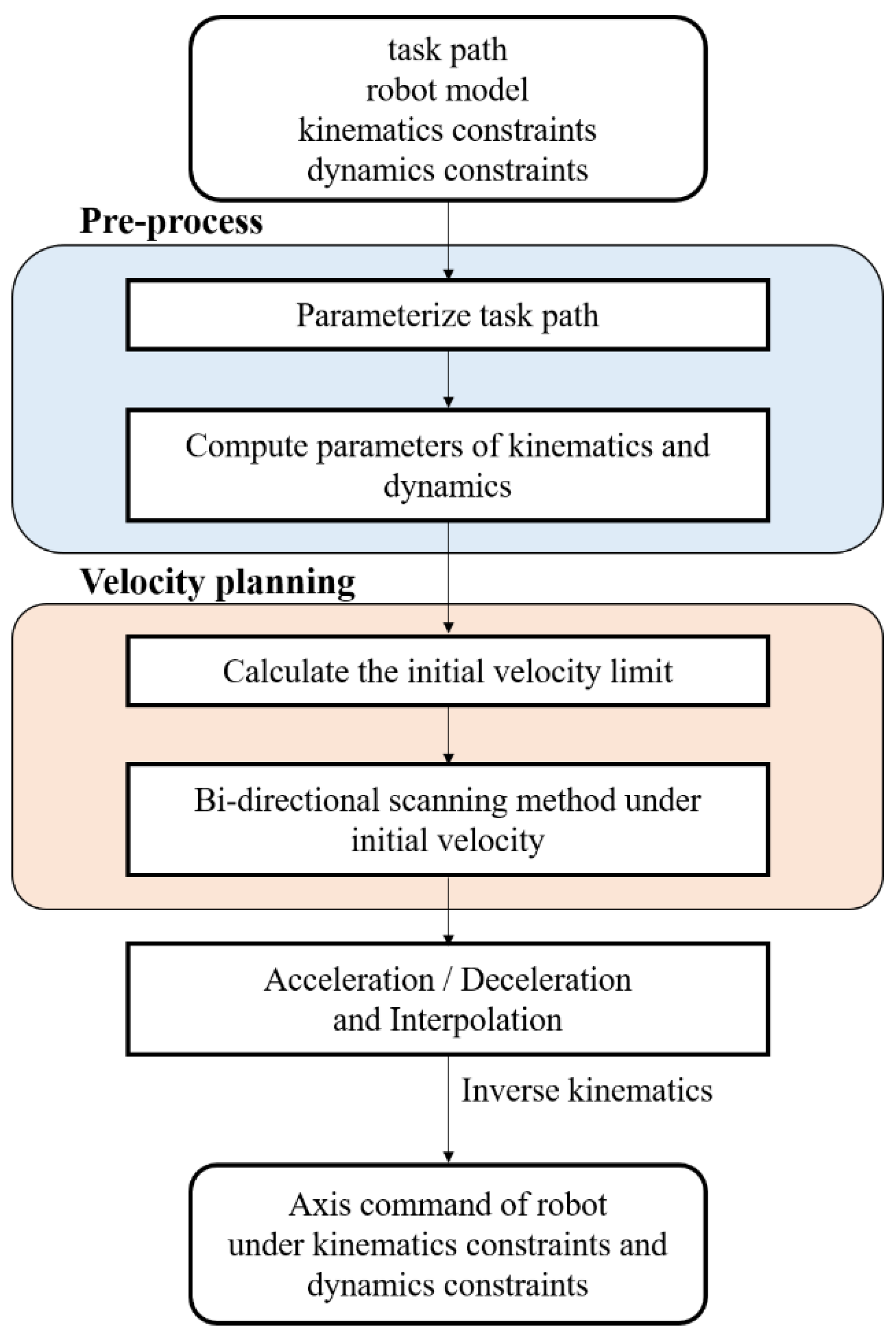
Figure 1. Schematic diagram of the proposed approach.
Electronics 14 03869 g001
Figure 2. Angular velocity planning result (PO motion).
Electronics 14 03869 g002
Figure 3. Simulation results of joint velocities (PO motion); red solid line: velocity limit; blue solid line: velocity.
Electronics 14 03869 g003
Figure 4. Simulation results of joint accelerations (PO motion); red solid line: acceleration limit; blue solid line: acceleration.
Electronics 14 03869 g004
Figure 5. Simulation results of joint torques (PO motion); red solid line: torque limit; blue solid line: torque.
Electronics 14 03869 g005aElectronics 14 03869 g005b
Figure 6. Velocity planning results (TO motion).
Electronics 14 03869 g006
Figure 7. Simulation results of joint velocities (TO motion); red solid line: velocity limit; blue solid line: velocity.
Electronics 14 03869 g007
Figure 8. Simulation results of joint accelerations (TO trajectory); red solid line: acceleration limit; blue solid line: acceleration.
Electronics 14 03869 g008
Figure 9. Simulation results of joint torques (TO motion) red solid line: torque limit; blue solid line: torque.
Electronics 14 03869 g009
Figure 10. Schematic diagram of the experimental platform.
Electronics 14 03869 g010
Figure 11. Velocity and tangential accelerations (TO motion).
Electronics 14 03869 g011
Figure 12. Experimental results of joint velocities (TO trajectory).
Electronics 14 03869 g012aElectronics 14 03869 g012b
Figure 13. Experimental results of joint accelerations (TO motion).
Electronics 14 03869 g013
Figure 14. Experimental results of joint torques (TO motion).
Electronics 14 03869 g014aElectronics 14 03869 g014b
Table 1. Kinematic constraints and dynamic constraints.
AxisJoint Velocity
(rad/s)
Joint   Acceleration   ( r a d / s 2 ) Joint Torque
(N·m)
11.023.0644.65
20.772.3140.66
31.163.4718.95
41.253.749.06
51.253.7410.05
61.865.55.69
Table 2. Pure orientation motion.
Parameter of TrajectoryStart PointEnd Point
X   ( m ) 0.300.30
Y   ( m ) 0.400.40
Z   ( m ) 0.300.30
α   ( r a d ) 3.142.44
β   ( r a d ) 0.000.96
γ   ( r a d ) 0.000.52
Table 3. Composite motion.
Parameter Start PointEnd Point
X   ( m ) 0.100.45
Y   ( m ) 0.40−0.35
Z   ( m ) 0.450.20
α   ( r a d ) 3.143.14
β   ( r a d ) 0.000.00
γ   ( r a d ) 0.170.44
Disclaimer/Publisher’s Note: The statements, opinions and data contained in all publications are solely those of the individual author(s) and contributor(s) and not of MDPI and/or the editor(s). MDPI and/or the editor(s) disclaim responsibility for any injury to people or property resulting from any ideas, methods, instructions or products referred to in the content.