Review

Vapor-Deposited Inorganic Perovskite Solar Cells from Fundamentals to Scalable Commercial Pathways

School of Energy Systems Engineering, Chung-Ang University, 84 Heukseok-ro, Dongjak-gu, Seoul 06974, Republic of Korea
*
Author to whom correspondence should be addressed.
Electronics 2025, 14(16), 3171; https://doi.org/10.3390/electronics14163171
Submission received: 8 July 2025 / Revised: 5 August 2025 / Accepted: 6 August 2025 / Published: 8 August 2025
(This article belongs to the Special Issue Materials and Properties for Solar Cell Application)

Abstract

Inorganic halide perovskites have garnered significant attention as promising candidates for photovoltaic and optoelectronic applications, owing to their enhanced thermal and chemical stability relative to hybrid perovskite materials. This review synthesizes recent progress in vapor-phase deposition methodologies, such as co-evaporation, close space sublimation (CSS), continuous flash sublimation (CFS), and chemical vapor deposition (CVD), which enable the precise modulation of film composition and morphology. Advances in material systems, including the stabilization of CsPbI2Br, the introduction of tin-doped phases, and the investigation of lead-free double perovskites like Cs2AgSbI6 and Cs2AgBiCl6, are critically evaluated with respect to their impact on device performance. The incorporation of these materials into photovoltaic devices and tandem configurations is explored, with particular emphasis on improvements in power conversion efficiency and operational durability. Furthermore, interface engineering approaches tailored to vacuum-deposited films—such as defect passivation and energy-level alignment—are examined in detail. The potential for scalable manufacturing is assessed through simulation analyses, throughput modeling, and pilot-scale demonstrations, underscoring the feasibility of industrial-scale production. By offering a comprehensive overview of these advancements, this review provides valuable perspectives on the current landscape and prospective trajectories of vapor-deposited inorganic perovskite technologies.

1. Introduction

The advent of halide perovskites has fundamentally transformed the photovoltaic landscape, achieving remarkable improvements in power conversion efficiencies (PCEs) within merely a decade of investigation [1,2,3]. Although early advancements predominantly involved organic–inorganic hybrid perovskites, their vulnerability to environmental stressors—including thermal, moisture, and photodegradation—has driven a strategic pivot toward fully inorganic variants, notably CsPbI3, CsPbI2Br, and CsPbBr3. These all-inorganic perovskites demonstrate enhanced thermal and chemical stability, sustained phase integrity under illumination, and superior resistance to ambient degradation [4,5,6]. Consequently, they are increasingly regarded as promising candidates for next-generation perovskite solar cells (PSCs), optoelectronic devices, and tandem configurations.
Despite these merits, the development of inorganic perovskites has encountered challenges such as suboptimal crystallization kinetics, intricate phase behavior, and inadequate film uniformity when employing conventional solution-processing techniques. To overcome these limitations, vapor-phase deposition methods have emerged as potent alternatives, offering precise modulation of composition, film thickness, and interfacial energetics while circumventing solvent usage and thermal annealing steps that often detract from film quality [7,8,9].
Seminal reviews by Bonomi and Malavasi [10] and Ullah et al. [11] have provided foundational insights into vapor-deposited perovskite materials and device performance, respectively. Nevertheless, as of mid-2025, an updated synthesis of recent progress is warranted to encompass advancements in scalability, industrial implementation, and the integration of vapor-deposited inorganic perovskite systems. Bonomi and Malavasi (2020) [10] broadly addressed physical and chemical vapor deposition (PVD and CVD) techniques applied to all-inorganic metal halide perovskites, focusing primarily on lead-containing and lead-free compositions with an emphasis on material stability and phase formation. In contrast, Ullah et al. (2021) [11] concentrated on evaporation-based approaches targeting CsPb(I1−xBrx)3 compositions but did not extend their analysis to the emerging fully lead-free perovskite class.
This review systematically and comparatively evaluates recent experimental progress (2021–2025) in vapor-phase deposition methodologies for inorganic perovskites. It highlights the evolution and application of techniques including co-evaporation, vacuum thermal evaporation (VTE), close-spaced sublimation (CSS), continuous flash sublimation (CFS), and chemical vapor deposition (CVD). These approaches facilitate solvent-free fabrication, enhanced film uniformity, and meticulous control over morphology, stoichiometry, and crystallinity—parameters critical for optimizing optoelectronic device performance. The review comprehensively addresses all principal vapor-phase methods, including CSS and CFS, providing a comparative analysis of their respective advantages and limitations. It encompasses a broad spectrum of materials, covering both lead-based and lead-free perovskite thin films, with particular attention paid to synthesis mechanisms and film morphology. Furthermore, the integration of vapor-deposited materials into functional devices, ranging from single-junction solar cells to tandem architectures [12,13], is examined. Special emphasis is placed on interface engineering strategies unique to vacuum deposition, such as molecular additive-assisted defect passivation and interlayer energy-level tuning, which are instrumental in enhancing device efficiency. Finally, recent strides toward process scalability are analyzed through simulation studies, throughput modeling, and pilot-line demonstrations, underscoring the commercial feasibility of these vapor-phase techniques. By consolidating these developments, this review aims to serve as a comprehensive reference and a forward-looking framework for advancing vapor-deposited inorganic perovskites toward large-scale implementation in sustainable energy technologies.

2. Deposition Techniques and Growth Pathways

This section provides a comprehensive examination of various vapor-phase deposition methodologies employed in the fabrication of inorganic perovskites, emphasizing not only the underlying technological principles, but also the resultant material quality, device performance, and scalability associated with each approach.

2.1. Mechanism of Perovskite Thin-Film Formation

The formation of perovskite films via vapor-phase deposition is governed by a complex interplay of vapor transport, surface adsorption, nucleation, and crystallization processes, all occurring under carefully controlled thermodynamic and kinetic conditions. In this process, solid precursors are thermally evaporated or sublimed within a vacuum or inert atmosphere. The vaporized species subsequently migrate toward a heated substrate, where they adsorb and diffuse across the surface. The mobility of these adatoms, which is influenced by substrate temperature and surface energy, facilitates the nucleation of critical clusters through classical nucleation mechanisms. As nucleation progresses and the film grows, the growth mode may follow one of several classical pathways: Volmer–Weber (island growth), Frank–van der Merwe (layer-by-layer growth), or Stranski–Krastanov (layer-plus-island growth). The specific growth mode realized depends on the interplay of interfacial energies and lattice mismatch between the substrate and the perovskite film.
In the context of perovskite deposition on arbitrary substrates lacking specific lattice matching, the Volmer–Weber island growth mode predominates, as perovskite grains exhibit stronger cohesion among themselves than adhesion to the substrate. Conversely, layer-by-layer growth (Frank–van der Merwe) or the hybrid layer-plus-island mode (Stranski–Krastanov) are more probable under near-epitaxial conditions, where the substrate–film interaction is pronounced, and the substrate lattice closely aligns with that of the perovskite [14,15]. In co-evaporation techniques, where all precursors are delivered simultaneously, crystallization occurs in situ via direct chemical reaction. In contrast, sequential or hybrid deposition methods involve the formation of intermediate phases and rely on solid-state diffusion to achieve the final perovskite structure. Post-deposition thermal annealing further promotes grain growth through Ostwald ripening and facilitates the conversion of intermediate or δ phases into the thermodynamically stable black α-perovskite phase. Throughout these processes, parameters such as substrate temperature, precursor flux ratio, deposition rate, and background pressure critically influence grain orientation, crystallinity, and the ultimate film morphology.

2.2. Significance of Vapor-Phase Deposition

Vapor-phase deposition methods (thermal evaporation, sputtering, and chemical vapor deposition, etc.) offer several advantages:
Solvent-Free, Cleaner Process: No liquid solvents are used, eliminating solvent-related defects and complexities. The deposition occurs in a dry vacuum or gas environment, which yields very uniform and smooth films without issues like solute aggregation. The resulting perovskite layers have shown a homogeneous thickness and microstructure over large areas [16].
Precise Composition Control: By controlling the evaporation rates of each precursor, one can precisely tune the film’s composition and even make multicomponent or mixed-halide perovskites with fine control. Vapor deposition allows for stoichiometric precision that is harder to achieve in solution processing. Complex architectures (e.g., graded or layered compositions) can be realized by simply changing the source flux in real time.
Conformal Coating on Rough or Large Substrates: Vapor deposition can coat non-planar or textured surfaces uniformly. This makes it well-suited for perovskite/silicon tandem cells.
Scalability and Industrial Compatibility: Vacuum deposition techniques (thermal evaporation, vapor transport, and sputtering, etc.) are already widely used in the electronics and solar industries, meaning that the know-how and equipment for large-area coating exist. These methods are inherently up-scalable to continuous or roll-to-roll manufacturing. Although thermal co-evaporation requires a vacuum, it can be integrated into high-throughput production lines with appropriate instrumentation.
Overall, vapor-phase deposition enables exceptional control over film formation, leading to high-quality perovskite layers with uniform coverage, tailored composition, and improved interface integration. These advantages make it a compelling approach for next-generation perovskite solar cells. Additionally, Table 1 delivers the potential advantages and limitations of various vapor deposition techniques.

2.3. Co-Evaporation and Sequential Deposition

Co-evaporation enables the simultaneous deposition of Cs- and Pb-based precursors. For instance, Z. Zhang et al. [17] utilized PEAI additives during the thermal co-evaporation of CsI and PbI2 to stabilize the γ-phase of CsPbI3, thereby achieving precise control over morphology and crystallinity, resulting in uniform, compact, and pinhole-free films [Figure 1a,b]. The resulting devices exhibit a notable power conversion efficiency of 15.0%, with enhanced stability over 215 days. This phase stability is crucial, since γ-CsPbI3 readily reverts to non-perovskite δ phase at room temperature without surface passivation.
M.H. Abib et al. [18] not only employed a one-step solution process to synthesize Sn-doped CsPbBr3 powders, but also utilized direct thermal evaporation to fabricate high-quality perovskite films from the as-prepared powders. Specifically, thermal evaporation of Sn-doped CsPbBr3 and undoped CsPbBr3 powders was performed to deposit uniform, pinhole-free films on FTO/TiO2 substrates. The resulting device structure, FTO/TiO2/Sn: CsPbBr3/carbon, exhibited an enhanced PCE of 8.95%. The incorporation of Sn improved crystallinity and promoted denser films, thereby reducing pinholes and grain boundary defects. SEM analyses confirmed increased grain size and fewer voids relative to undoped devices [Figure 1c].
Sequential evaporation is another approach where layers can be deposited in a predetermined order. M. H. Lee et al. [19] successfully fabricated CsPbI2Br perovskite films using a sequential vacuum deposition method, offering a controlled approach to grow high-quality all-inorganic perovskite layers. The process involves the thermal evaporation of CsBr, followed by PbI2. It produced larger grains with a reduced number of pinholes due to more efficient nucleation compared to the sequential deposition of PbI2 and then CsBr [Figure 1d]. The resulting CsPbI2Br solar cells achieved a 13.41% PCE.
It is further demonstrated that post-deposition annealing could be minimized if the deposition order and substrate temperature were optimized, contributing to better throughput for industrial processes. Y. Gupta et al. [20] demonstrate the fabrication of uniform CsPbI2Br inorganic perovskite absorbers using the three-source thermal evaporation method [Figure 1e], tailored for monolithic all-perovskite tandem solar cells. Moreover, some studies suggest comparing single-source versus dual-source evaporation for CsPbBr3. While single-source evaporation offers a simpler operation, dual-source evaporation allows for greater control over halide composition and film uniformity, resulting in a smoother surface morphology and reduced defect states [21].

2.4. Electron Beam and CVD Approaches

Strategies such as the single-source electron beam evaporation technique [Figure 2a], followed by post-annealing treatment, can successfully fabricate high-quality and full-coverage CsPbBr3 thin films. Although convenient, this method led to the unintentional formation of secondary phases such as CsPb2Br5 when deposition parameters were not strictly controlled. The use of a Br-rich evaporation source, consisting of CsPbBr3 and Cs4PbBr6 powders, effectively suppresses the formation of the non-perovskite CsPb2Br5 phase, leading to improved film crystallinity and uniformity. The resulting perovskite solar cells exhibited a PCE of 7.81% with an open-circuit voltage of 1.43 V, demonstrating the potential of this technique for scalable and stable all-inorganic perovskite solar cells [22]. Z. Su et al. [23] explored the crystallization mechanism and lasing properties of CsPbBr3 perovskite microstructures fabricated via CVD [Figure 2b]. Various microcavity shapes, including hemispheres, rods, plates, and pyramids, were synthesized by systematically adjusting parameters such as local temperature, substrate type, carrier gas flow rate, and air pressure. The study provided insights into how these factors influence crystal morphology and how optical characteristics describe the utility of CVD for producing tunable micro–nano perovskite structures for advanced optoelectronic devices.

2.5. High-Throughput Methods: CSS and CFS

J. Ihrenberger et al. [12] reported CSS as a fast, scalable, and solvent-free technique for growing CsPbBr3 polycrystalline films. By optimizing the deposition temperature and using a synthesized CsPbBr3 source via ball milling, the study achieves single-phase films with a growth rate of up to 10 μm/min and material utilization as high as 98% [Figure 2c]. The CSS process benefits from a high growth rate and minimal contamination, making it suitable for large-area applications. This work provides a comprehensive analysis of how deposition parameters impact film quality, offering a competitive alternative for industrial perovskite film production.
T. Abzieher et al. [24] introduce continuous flash sublimation (CFS) as a novel vapor deposition approach to address the rate and scalability limitations of conventional methods [Figure 2d]. The CFS process enables the deposition of high-quality CsPb(IxBr1−x)3 thin films across the entire iodine–bromine compositional spectrum in under five minutes. By leveraging mechano-chemically synthesized powders and a controlled high-temperature sublimation setup, the method ensures compositionally uniform and optically homogeneous films. Compared to traditional thermal evaporation, CFS reduced the total deposition time by ~80% while maintaining film uniformity, offering significant potential for roll-to-roll manufacturing.

2.6. Pulsed Laser Deposition (PLD)

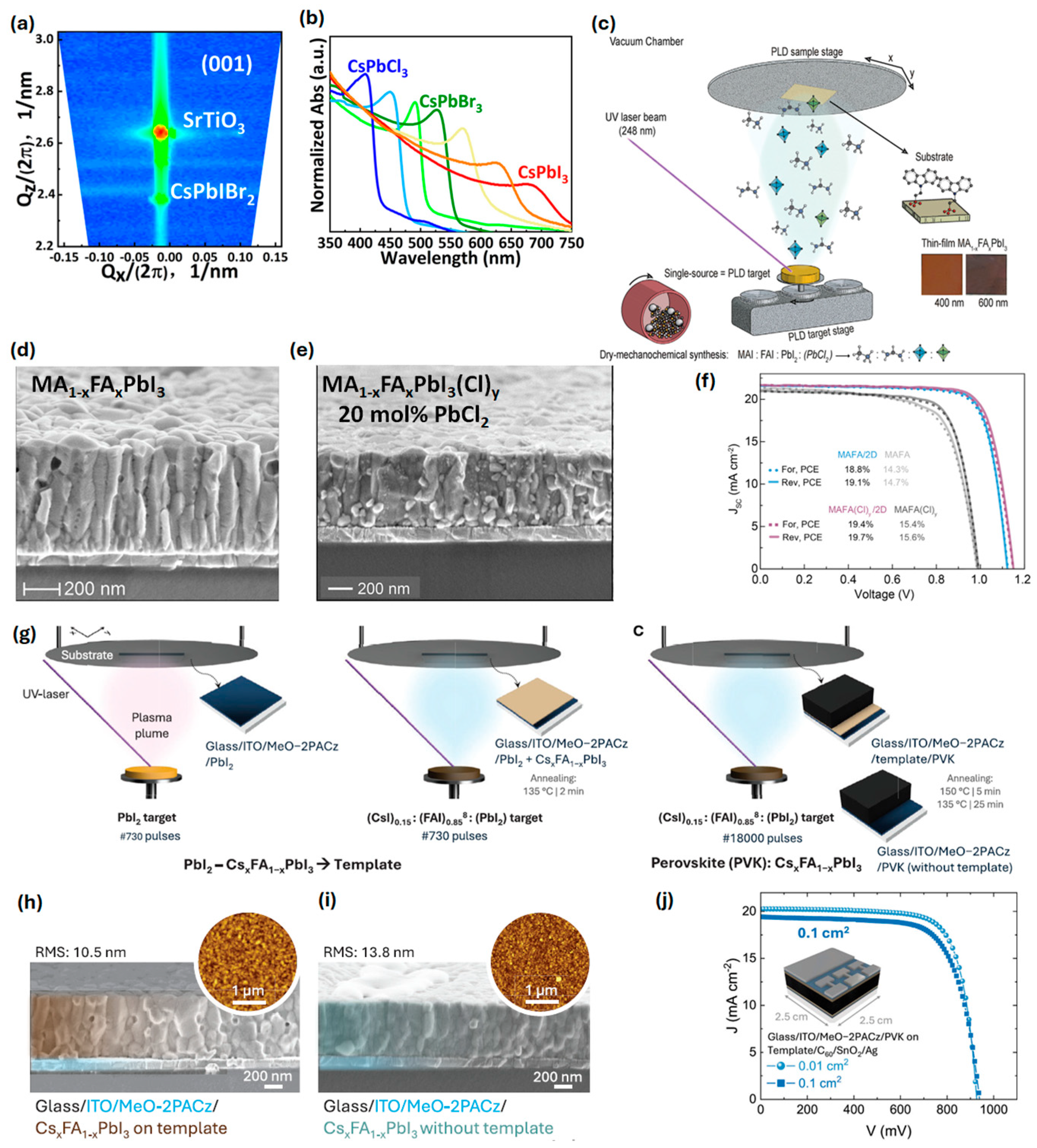
The vapor-phase epitaxial growth of all-inorganic mixed-halide perovskites CsPb(IxClyBr1-x-y)3 on lattice-matched SrTiO3 (001) substrates using the PLD technique is another excellent approach for fabricating inorganic perovskite films via solvent-free methods [Figure 3a]. By ablating pressed halide perovskite targets with a KrF excimer laser, 90 nm-thick single-crystalline films with tunable halide compositions were deposited, covering bandgaps from ~1.76 eV (CsPbI3) to ~2.98 eV (CsPbCl3) [Figure 3b]. The films grew in cube-on-cube epitaxy on the SrTiO3 substrate, yielding phase-pure cubic perovskite domains with excellent crystallinity [25].
Soto-Montero et al. demonstrated a single-source PLD approach to fabricate mixed-cation MA1−xFAxPbI3 perovskite thin films doped with chloride [Figure 3c]. A composite PLD target containing methylammonium iodide (MAI), formamidinium iodide (FAI), PbI2, and PbCl2 (with excess organic content to compensate for volatility) was ablated to deposit uniform perovskite layers in one step. The as-grown films showed compact, columnar grains with full surface coverage [Figure 3d,e]. In inverted p–i–n solar cells (ITO/2PACz hole contact), these PLD films achieved a PCE of up to 19.7% with Voc~1.11 V and high fill factors ~80% [Figure 3f] [26].
Kralj et al. developed a template-assisted PLD method to grow CsxFA1−xPbI3 perovskite films, achieving phase-pure α-Cs0.2FA0.8PbI3 absorbers for single-junction solar cells. In this two-step seeding approach, a ~20 nm PbI2 layer is first deposited (at RT) on the substrate, followed by ~20 nm of Cs0.2FA0.8PbI3; brief annealing of this bilayer creates a template that induces the perovskite’s desired cubic α-phase nucleation. The remaining ~600–650 nm of the perovskite is then deposited via PLD from a single mixed-precursor target and crystallized with a final anneal, yielding a thick, uniform film [Figure 3g]. This template strategy was critical to obtain phase-pure, photoactive perovskite: films grown without the PbI2 template showed δ-phase impurities and islanded growth, especially on textured substrates, whereas templated films grew as pure α-phase CsxFA1−xPbI3 with full coverage [Figure 3h–i]. Solar cells made with the templated α-Cs0.2FA0.8PbI3 films achieved PCE~12.9% on 0.1 cm2 devices without any additional passivation layers. The champion devices showed Voc ~1.05 V and respectable fill factors 70% [Figure 3j] [27].
Table 1. A comparative table of key advantages and limitations of various vapor deposition techniques.
Deposition MethodKey AdvantagesLimitationsRef.
Co-evaporation- Enables high-quality perovskite films.
- Precise composition control.
- Produces uniform, pinhole-free layers.
- Excellent film reproducibility.
- Multiple evaporation sources can be co-utilized.
- All-dry fabrication process.
- Low deposition rates (typically 1–10 nm/min).
- Impractical for high-volume manufacturing.
- Requires high-vacuum systems and careful calibration of multiple sources.
- Organic salts can thermally decompose during heating.
[24,28,29]
Sequential Deposition- Deposits components in separate steps.
- Avoids the flux-balancing difficulties of co-evaporation.
- Optimizes processing for each component.
- Allows for better control of crystallization.
- Different cations or halides can be introduced in successive evaporation steps.
- Incomplete conversion can create sub-optimal interfaces and trap states.
- Requires a post-deposition anneal to form the perovskite.
- Increases the process time and complexity relative to one-step co-evaporation.
- Multiple sequential vacuum steps in a large-scale manufacturing line can be challenging.
[28]
Chemical Vapor Deposition (CVD)- Excellent uniformity and coverage.
- Feasible to calibrate the input of each precursor.
- Widely used in industry for large-area deposition.
- Can be run in continuous mode.
- Solvent-free approach.
- Feasible to integrate CVD with other processes in a single reactor sequence.
- High temperature 150–300 °C (or higher) requirements.
- Equipment complexity and safety.
- Batch processing in practice.
[28]
Close-Spaced Sublimation (CSS)- Low vacuum requirement (~1–100 mbar) and high throughput.
- Enables rapid deposition over large areas.
- High material utilization with minimal waste.
- Simplified process control.
- Scalability and industrial relevance in device manufacturing.
- Involves a multi-step process.
- Equipment and uniformity considerations.
- Slight efficiency gap in fully dry CSS.
- Limits the use of temperature-sensitive substrates.
[30]
Continuous Flash Sublimation (CFS)- Ultrafast deposition rates, faster than conventional co-evaporation.
- Critical for industrial roll-to-roll processing.
- Continuous processing capability.
- Scalable manufacturing for perovskite films.
- The flash process yields homogeneous nucleation and crystal growth.
- Currently limited to inorganic compositions.
- Pre-synthesis of source material adds complexity and cost.
- Post-annealing (e.g., >300 °C) requirement limits compatible substrates and slightly complicates a continuous process.
- Equipment and scale-up challenges.
- Powder handling and safety issues.
[24]
Pulsed Laser deposition (PLD)- Deposits a wide range of materials.
- Allows for fine control of film thickness, enabling high-quality films.
- High deposition rates (~6 to 80 nm/min).
- Multiple targets can be used sequentially.
- An all-dry, physical vapor process.
- The deposition plume is highly directional.
- PLD systems are relatively expensive due to the need for high-power pulsed lasers and high vacuum power.
- The high-energy laser can risk damaging or decomposing volatile components.
[31,32]

3. Composition and Phase Engineering

This section delves into the material-specific engineering of vapor-deposited inorganic perovskites, focusing on their halide composition, cation tuning, defect chemistry, and emerging alternatives to lead-based systems. Special attention is given to how these factors influence crystal structure, phase stability, and optoelectronic performance.

3.1. CsPbX3-Based Systems

Among the most studied inorganic halide perovskites are CsPbI3, CsPbI2Br, and CsPbBr3, each with distinct bandgaps (~1.73 eV, ~1.9 eV, and ~2.3 eV, respectively). CsPbI3 is attractive due to its near-ideal bandgap for single-junction solar cells, but suffers from structural instability, particularly the transformation from the optoelectronically active black phase to the yellow non-perovskite phase under ambient conditions. Strategies to stabilize CsPbI3 include PEAI surface passivation during co-evaporation and crystallization at elevated substrate temperatures [17,20].
Vapor-phase deposition techniques offer unique advantages for fabricating inorganic perovskite thin films (CsPbI3 and CsSnI3) with superior purity, stability, and microstructural quality compared to solution processing. Because these methods occur in a solvent-free, high-vacuum (inert) environment, the resulting films are free of organic residues or unwanted byproducts; for example, the co-evaporation of CsI and PbI2 yields pure all-inorganic CsPbI3 with no incorporation of dimethylammonium (a contaminant that can arise from DMF/HI solution routes) [33]. This high chemical purity and precise stoichiometric control translate to improved phase stability. Vapor-deposited CsPbI3 can be obtained directly in the black perovskite phase without the solvent additives needed in solution, avoiding the metastable-to-yellow phase conversion; in one case, vacuum-deposited CsPbI3 films even formed minor Cs4PbI6 inclusions that helped lock the desirable black phase at room temperature.
CsPbI2Br offers a balance between stability and band alignment. Sequential thermal evaporation using a CsBr layer followed by PbI2 successfully formed phase-pure CsPbI2Br with vertically aligned grains and minimal pinholes [Figure 4a,b] [19]. Comparable results were corroborated through AFM studies, confirming strong c-axis orientation and smooth surfaces. Furthermore, CsPbI2Br/FPEAI was integrated into a triple-junction device [Figure 4c,d], highlighting the relevance of vapor-grown perovskites in multi-junction architectures [20].
Meanwhile, CsPbBr3 stands out for its superior environmental stability and optical clarity, making it suitable for tandem and semi-transparent applications. However, it often exhibits high trap densities and limited light absorption due to its wider bandgap. Optimization via vapor co-evaporation has yielded films with improved crystallinity and better grain morphology compared to the spin-coating-deposited film [Figure 4e] [34]. CsPbI2Br offers improved air stability while maintaining decent voltage output and crystallinity.

Dopants and Defect Passivation

Defect tolerance and passivation strategies are critical for ensuring long-term performance. Sn doping, as explored in [18], enhances carrier mobility and reduces trap-assisted recombination by partially substituting Pb2+ with Sn2+, resulting in enlarged grains and reduced sub-gap states. Photoluminescence quantum yield (PLQY) studies in this work showed improvement compared to undoped controls [Figure 5a].
Interfacial passivation is another key theme. The use of CuSCN as a hole transport layer (HTL), combined with CsBr buffer layers, was shown to mitigate interface defect density [35], as depicted in Figure 5b,c. This study demonstrated that CsBr not only improved band alignment, but also suppressed moisture-induced degradation pathways.
An innovative approach presented by R. Guo et al. [36] involves designer ionic molecules like 4-(dimethylamino)-1-(2,2,2-trifluoroacetyl) pyridin-1-ium 2,2,2-trifluoroacetate (DTPT). These molecules exhibit dual functionality, anchoring to undercoordinated lead sites while passivating halide vacancies, thus simultaneously enhancing both crystallinity and operational stability. DTPT-modified CsPbBr3 exhibits a longer charge carrier lifetime (27 ns) compared to CsPbBr3 (4.5 ns) ascribed to the suppression in non-radiative recombinations [Figure 5d–f]. Devices treated with DTPT retained over 90% of their initial efficiency after 100 days under ambient conditions. Interestingly, the introduction of CsBr-rich growth conditions intentionally forms 0D Cs4PbBr6 inclusions within the CsPbBr3 matrix. These inclusions assist in surface passivation, especially to improve optoelectronic applications [37].
Sn doping enhances charge transport and crystallinity, while CsBr buffer layers mitigate CuSCN-induced degradation [18,35]. Ionic liquids such as DTPT provide the multifunctional passivation of surface defects (e.g., Cs+ and Br vacancies), leading to long-term stable and high-efficiency devices (11.21% at 0.04 cm2, >90% retention after 100 days) [36].

3.2. Lead-Free Alternatives

3.2.1. CsSnX3-Based Systems

CsSnI3 films synthesized within an oxygen-free vapor environment preserve the black CsSnI3 phase (β-γ phase) and effectively inhibit oxidation to the undesirable Sn(IV) phase, specifically the insulating Cs2SnI6 [38]. Furthermore, vapor-phase growth facilitates superior crystallinity and grain morphology; the absence of rapid solvent evaporation allows crystals to have extended time and thermal energy to organize into larger, well-ordered grains. Additionally, vapor-phase processes enable the incorporation of additives to further enhance film quality. For example, during the sequential evaporation of CsSnI3 with a volatile PbCl2 additive, chlorine was observed to alloy into the lattice and subsequently evaporate during annealing, thereby improving film crystallinity and promoting the uniform growth of large, vertically oriented grains [39]. Such films generally exhibit reduced grain boundary density and lower defect concentrations. Moreover, vapor-phase deposition techniques demonstrate exceptional control over thickness and compositional uniformity across large areas. Notably, large-area CsSnI3 films produced via vacuum deposition have been reported to possess high uniformity, effectively addressing reproducibility and scalability challenges associated with solution-based coating methods. Consequently, vapor deposition methods yield compact, high-purity perovskite films characterized by stable crystal phases, enhanced grain structure, diminished defect densities (eliminating solvent traps and voids), and excellent uniformity.
Bonomi et al. present radio frequency (RF) magnetron sputtering as a versatile vapor-phase deposition technique for synthesizing three distinct cesium–tin–bromide compounds: the three-dimensional perovskite CsSnBr3, the two-dimensional layered perovskite CsSn2Br5, and the vacancy-ordered perovskite Cs2SnBr6. Utilizing a single pressed target composed of CsBr and SnBr2, the authors demonstrate that selective phase formation can be achieved by adjusting sputtering parameters and applying mild post-deposition annealing. Specifically, substrate heating to 200 °C during deposition facilitates the formation of CsSnBr3; deposition at room temperature without substrate heating yields CsSn2Br5; and subsequent annealing at 200 °C converts the films into Cs2SnBr6. This methodology leverages the far-from-equilibrium conditions inherent to sputtering, enabling the stabilization of perovskites and related phases that are typically difficult to obtain through solution-based synthesis. Although the study does not extend to the fabrication of functional solar cells, it establishes foundational processing insights for the integration of Cs-Sn-Br materials into device architectures [40].
Jung et al. [41] reported the fabrication of lead-free perovskite alloy CsSn1−xZnxBr3 thin films (with x ranging from 0 to 1) on glass substrates via the co-evaporation of CsBr, SnBr2, and ZnBr2. The deposition process was conducted using a dual-source vacuum thermal evaporation system operating at a base pressure of approximately 1.0 × 10⁻⁴ Pa, wherein the effusion rates of CsBr and SnBr2 were precisely regulated (see Figure 6a). By systematically varying the substrate temperature (T = 20, 80, and 120 °C) and the supply ratio r = (SnBr2, ZnBr2)/CsBr, the authors optimized the growth conditions to obtain phase-pure CsSnBr3 films devoid of secondary phases. The optimal parameters for undoped CsSnBr3 were identified as a substrate temperature near 80 °C combined with a slight excess of SnBr2 (r = 1.12), resulting in uniform films that were approximately 500 nm thick without detectable impurities such as Cs2SnBr6 or CsSn2Br5. Subsequently, ZnBr2 was incorporated into the vapor flux to facilitate alloying. The study demonstrated the successful incorporation of Zn into the perovskite lattice up to a concentration of x = 0.04. At this doping level, the alloyed films exhibited improved morphological characteristics, including enlarged grain size, absence of pinholes, and a relatively smooth surface. Moreover, Zn incorporation was found to mitigate the prevalent issue of Sn2+ oxidation in CsSnBr3 and reduce non-radiative defect states, which are anticipated to enhance charge transport properties (see Figure 6b–d).
The first synthesis of two-dimensional CsSnI3 nanosheets using a space-confined CVD method was reported by Yin et al. [42]. The CsSnI3 source (typically CsI and SnI2 precursors or pre-made CsSnI3 powder) is heated in a CVD setup, and the key innovation is a small gap (on the order of sub-millimeter to a few millimeters) imposed between the growth substrate and a confining cover substrate [Figure 6e]. The confined geometry creates a quasi-closed micro-reactor space that limits gas-phase transport and provides a controlled supersaturation environment for 2D growth. By varying the gap distance and growth temperature, the researchers could tune the thickness and lateral dimensions of the resulting CsSnI3 crystals with precision [Figure 6f]. While no device metrics are reported here, the uniform PL and fast excitonic recombination indicate that these nanosheets could support efficient charge extraction if coupled to contacts. The integration with WSe2 also hints at the possibility of building all-vapor-fabricated photovoltaic junctions (e.g., a CsSnI3/WSe2 solar cell) where the perovskite absorbs light and the 2D semiconductor transports one carrier type [Figure 6g,h]. Yin et al. [42] first reported the synthesis of two-dimensional CsSnI3 nanosheets via a space-confined chemical vapor deposition (CVD) technique. In this method, the CsSnI3 source—commonly comprising CsI and SnI2 precursors or pre-synthesized CsSnI3 powder—is heated within a CVD apparatus. A critical innovation involves introducing a narrow gap, ranging from sub-millimeters to a few millimeters, between the growth substrate and an overlying confining cover substrate (see Figure 6e). This confined geometry establishes a quasi-closed micro-reactor environment that restricts gas-phase transport and facilitates a controlled supersaturation condition conducive to two-dimensional crystal growth. By systematically adjusting the gap distance and growth temperature, the researchers achieved precise control over the thickness and lateral dimensions of the resulting CsSnI3 nanosheets (Figure 6f). Although device performance metrics were not provided, the observed uniform photoluminescence and rapid excitonic recombination suggest that these nanosheets possess the potential for efficient charge extraction when integrated with electrical contacts. Furthermore, the successful integration with WSe2 indicates the feasibility of fabricating all-vapor-deposited photovoltaic heterojunctions, such as CsSnI3/WSe2 solar cells, where the perovskite layer functions as the light absorber and the two-dimensional semiconductor facilitates selective carrier transport (Figure 6g,h).
Li et al. [43] developed a solid additive-assisted chemical vapor deposition (CVD) technique to fabricate high-quality CsSnI3 thin films with minimized defect formation. Unlike conventional solution-based methods, this approach employs bulk CsSnI3 powder, synthesized via a high-temperature solid-state reaction (as illustrated in Figure 6i), as the evaporation source within a CVD tube furnace. A key innovation involves introducing the solid additive N,N’-methylene-bis(acrylamide) (MBAA) into the deposition chamber, where it sublimes concurrently with the perovskite precursor. Under deposition conditions—specifically, a source zone temperature of approximately 500 °C and a nitrogen atmosphere at ~0.28 Torr—the vaporized MBAA establishes a coordination-rich environment that interacts with the growing film. The carbonyl (C=O) functional groups in MBAA possess lone pair electrons capable of coordinating with Sn2+ ions at the film growth interface, thereby inhibiting their oxidation to Sn4+ and passivating tin vacancies (see Figure 6j–l). This coordination mechanism effectively suppresses the generation of Sn4+ species and related defect states during film formation. Consequently, the process yields phase-pure, black orthorhombic CsSnI3 (β-γ phase) films exhibiting significantly reduced intrinsic defect densities. Importantly, this entirely vapor-phase method circumvents the use of organic solvents, thereby advancing environmentally sustainable fabrication strategies for perovskite materials.
Figure 6. (a) Schematic representation of vapor deposition of CsSn1−xZnxBr3 perovskite film. (b,c) SEM micrographs of vapor-deposited pure CsSnBr3 and CsSn1−xZnxBr3 (Zn x = 0.04). (d) Time-resolved photoluminescence carrier dynamics of CsSn1−xZnxBr3 (Zn x = 0, 0.04), reproduced with permission, (2023) IOP Publishing [35]. (e) Diagram illustrating the space-confined growth of two-dimensional CsSnI3. (f) Optical images with corresponding atomic force microscopic images of CsSnI3 nanosheets developed at 0.5, 1.5, and 2.0 mm distances. (g,h) Band alignment representation of CsSnI3/WSe2 heterostructure and corresponding photoluminescence of WSe2 and CsSnI3/WSe2, reproduced with permission, (2024) American Chemical Society [36]. (i) The obtained CsSnI3 ingots are sealed in an evacuated quartz tube. (jl) SEM micrographs and corresponding photoluminescence of CsSnI3 without and with MBAA additive, reproduced with permission, (2025) John Wiley and Sons [37]. (m) Schematic illustration of Cs2AgSbI6 through ion exchange in Cs2AgSbBr6 perovskite. (n) UV-Vis absorbance spectra of Cs2AgSbI6 formation through anion conversion reaction. (o) Room temperature PL and absorption spectrum of complete Cs2AgSbI6 perovskite phase, reproduced with permission, (2025) American Chemical Society [44].
Electronics 14 03171 g006

3.2.2. Double Perovskites

With increasing scrutiny over Pb toxicity, lead-free double perovskites have emerged as promising alternatives. Cs2AgSbI6 and Cs2AgSbCl6, both featuring monovalent and trivalent metal cations, possess indirect bandgaps (~1.8–2.9 eV) and exceptional air stability. Faris Horani and Daniel R. Gamelin [44] report the synthesis of colloidal Cs2AgSbI6 nanocrystals via the hot injection anion exchange method [Figure 6m–o]. The resulting materials exhibited strong absorption in the visible range, and their photoluminescence lifetime measurements suggested moderate exciton-binding energies suitable for photovoltaic applications.
Meanwhile, P. Jain et al. [45] used vacuum deposition to fabricate Cs2AgBiCl6 films and performed detailed spectroscopic analysis. The study uncovered strong self-trapped exciton emissions and identified both direct and indirect band transitions. These findings imply potential use in low-energy photonics and light-harvesting platforms, especially under UV exposure. Recent reports on Cs2AgSbI6 (Eg ~ 1.8 eV) and Cs2AgBiCl6 (Eg ~ 2.9 eV) demonstrate pathways to fully lead-free and air-stable materials. Though their efficiencies remain modest, these systems provide unique optical features such as self-trapped excitons, relevant for quantum-cutting and lighting applications [44,45].

4. Device Performance and Functional Integration

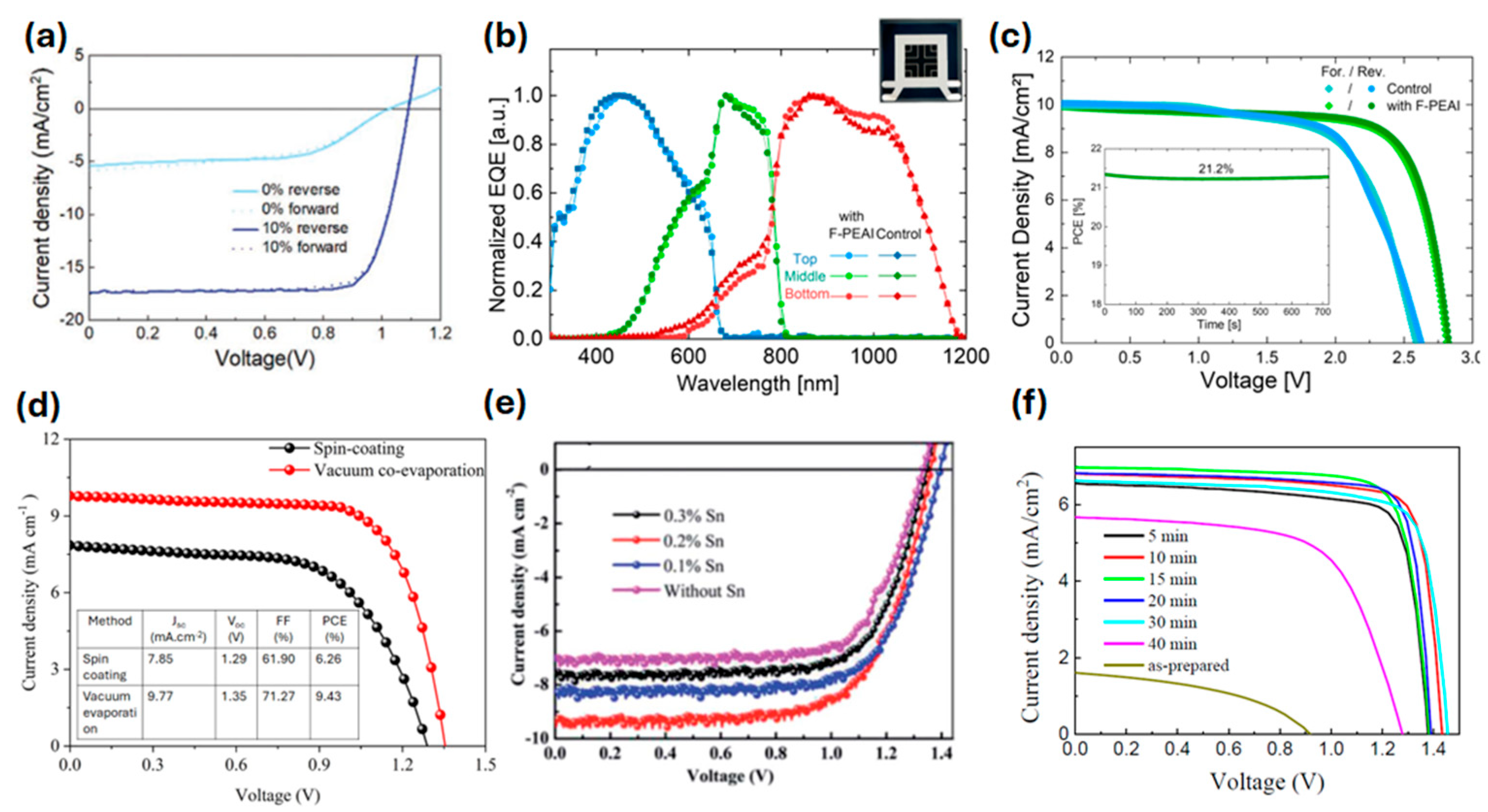
Device-level metrics are crucial for assessing the viability of vapor-deposited inorganic PSCs. In this section, we summarize key performance indicators, including PCE, operational stability, and scalability, as reported across multiple studies in Table 2. A co-evaporated γ-CsPbI3 device treated with PEAI demonstrated a 15.0% PCE and retained over 90% of its initial performance after 215 days of ambient storage [Figure 7a]. This performance is attributed to enhanced phase stability and trap suppression from the organic additive [17].
The use of CsPbI2Br as a photoabsorber, deposited via sequential evaporation, has led to efficiencies exceeding 13% in multiple studies. For example, M. H. Lee et al. [19] employed a bilayer growth sequence (CsBr followed by PbI2), resulting in vertically aligned grains and minimal pinholes. The devices achieved a 13.41% PCE with good reproducibility, while Y. Gupta et al. [20] successfully integrated the same composition into a triple-junction solar cell, where it functioned as the top cell, with excellent photostability [Figure 7b,c]. For CsPbBr3, a co-evaporated device had a 9.43% PCE [Figure 7d] and >96% retention after 480 h of continuous exposure to ambient air [31]. When introducing DTPT as a molecular passivation agent, it achieved a PCE of 11.21% on small devices and 9.18% on 1 cm2 active areas, with stability retained over 100 days [36]. Sn-doped CsPbBr3 devices fabricated via thermal evaporation yielded a 8.95% PCE [Figure 7e], with improved film density and uniformity [18]. Meanwhile, e-beam-evaporated CsPbBr3 films showed a 7.81% PCE [Figure 7f] with high open-circuit voltages (~1.43 V) [22]. M. I. P. Monroy et al. [46] demonstrate the fabrication of all-inorganic CsPbI3 films using a fully vacuum-based co-evaporation process, resulting in uniform and compact γ-phase perovskite films without requiring post-treatment. These films showed excellent optoelectronic properties, and the corresponding solar cells achieved a PCE of 8.84%.

5. Interface Engineering and Emerging Applications

Interface quality is a major determinant of device performance in perovskite photovoltaics, especially under vapor-phase processing, where interlayer reactions and energetic misalignments can limit charge extraction and stability.

5.1. Energy-Level Control

J. Zhang et al. [47] reveal that CsPbI2Br films fabricated via vacuum evaporation have better film quality, defect-free surfaces, and improved crystallization [Figure 8a,b]. Vacuum-deposited films show reduced hole injection barriers (~0.4 eV) when interfaced with rubrene compared to spin-coated films (~0.6 eV), which suffer from iodine vacancies and dangling bonds, revealing significant differences in energy level alignment [Figure 8c,d]. The interfacial interactions are markedly different due to the presence of chemical bonding in the spin-coated case versus physical interaction in the vacuum-evaporated films. These findings underscore the significance of fabrication methods in interfacial energetics and suggest vacuum evaporation as a superior technique for optimizing charge injections in perovskite-based optoelectronic devices. Furthermore, Y. Liao et al. [35] demonstrated that introducing a CsBr interlayer between the absorber and CuSCN hole transport layer mitigated band bending and Fermi level pinning. This interface engineering led to improved Voc and enhanced ambient stability over 500 h [Figure 8e].

5.2. Patterned Growth and Photonic Integration

In recent research, Z. Xu et al. [48] introduced a surface energy-assisted patterning and vapor deposition (SEAPVD) strategy to create high-resolution, all-inorganic perovskite arrays with tunable shapes and compositions [Figure 8f]. By modifying the substrate surface energy, the nucleation and growth of perovskite films are precisely controlled, achieving up to a 423 dpi resolution and exceptional photo response metrics like a responsivity of 47.5 A.W−1. The fabricated arrays also show durability under humid conditions and viability in wearable optoelectronic applications, including continuous pulse monitoring.
Inorganic halide perovskites, particularly Cs-based compositions like CsPbBr3 and CsSnI3, have demonstrated controlled and patterned growth via solvent-free vapor-phase deposition techniques such as chemical vapor deposition (CVD) and thermal evaporation. Zhong et al. report the formation of centimeter-scale thin CsPbBr3 single-crystal films on c-plane sapphire substrates using a low-pressure CVD method. The growth is guided by lattice matching and interfacial strain, which favor oriented epitaxial growth via a vapor–solid mechanism. Notably, this approach enables phase-pure orthorhombic CsPbBr3 with sharp edges and micron-level domain control without post-processing, indicating a high degree of spatial order and phase stability during crystallization [49]. In a separate study, Reo et al. developed patterned CsSnI3 perovskite films using the sequential vapor deposition of SnI2, CsI, and PbCl2 on SiO2 substrates. Here, PbCl2 acts as a reaction initiator, accelerating solid-state diffusion and promoting cascade-like grain fusion upon annealing. This thermally driven vapor–solid transition allows for grain enlargement and improved homogeneity [39]. These results highlight how vapor-phase strategies facilitate substrate-guided, spatially controlled perovskite growth without solvents, achieving large-area uniformity, tunable crystal orientation, and superior electronic properties critical for optoelectronic and microelectronic integration. Such patterned, epitaxial, or quasi-epitaxial growth is difficult to achieve through solution methods due to uncontrollable nucleation and solvent-induced phase impurities.
Inorganic halide perovskites, particularly cesium-based compositions such as CsPbBr3 and CsSnI3, have exhibited controlled and patterned growth through solvent-free vapor-phase deposition techniques, including chemical vapor deposition (CVD) and thermal evaporation. Zhong et al. demonstrated the synthesis of centimeter-scale thin films of single-crystal CsPbBr3 on c-plane sapphire substrates employing a low-pressure CVD approach. The growth process is directed by lattice matching and interfacial strain, which facilitate oriented epitaxial growth via a vapor–solid mechanism. Importantly, this method yields phase-pure orthorhombic CsPbBr3 with well-defined edges and micron-scale domain control without requiring post-deposition processing, indicating a high degree of spatial order and phase stability during crystallization [49]. In a related investigation, Reo et al. fabricated patterned CsSnI3 perovskite films through the sequential vapor deposition of SnI2, CsI, and PbCl2 on SiO2 substrates. In this system, PbCl2 functions as a reaction initiator, enhancing solid-state diffusion and promoting cascade-like grain fusion upon annealing. This thermally induced vapor–solid transition facilitates grain growth and improves film homogeneity [39]. Collectively, these findings underscore the efficacy of vapor-phase methodologies in enabling substrate-directed, spatially controlled perovskite growth without the use of solvents, achieving large-area uniformity, tunable crystal orientation, and enhanced electronic properties essential for optoelectronic and microelectronic applications. Such patterned, epitaxial, or quasi-epitaxial growth is challenging to realize via solution-based methods due to uncontrollable nucleation processes and solvent-related phase impurities.

6. Scalability and Industrial Pathways

Scalability remains a critical bottleneck in translating lab-scale vapor-deposited perovskite technologies into large-scale production. This section examines recent efforts to address throughput, yield, and cost considerations through both the modeling and implementation of continuous vapor-phase manufacturing.

6.1. Process Modeling and Throughput Optimization

J. Petry et al. [13] presented a comprehensive simulation of a horizontal multi-source evaporation system, analyzing variables such as crucible spacing, substrate velocity, and source geometry. The model predicted that by deploying modular co-evaporation heads in parallel and adjusting substrate transport speed, a throughput exceeding 1000 M10-sized wafers per hour could be achieved. This level of scalability is competitive with current silicon PV manufacturing rates.
The authors identified several engineering strategies critical for scale-up. Angled crucible nozzles were implemented to maximize vapor flux delivery and reduce precursor loss, thereby improving material utilization. Furthermore, the integration of real-time optical monitoring systems enabled the precise control of film thickness and compositional uniformity throughout the deposition process. Lastly, the development of vacuum-compatible linear motion stages allowed for continuous substrate movement, supporting large-area coating and consistent film deposition across industrial-scale wafers.
The study also evaluated the trade-offs between material utilization and deposition uniformity, concluding that crucible tilt and substrate temperature must be co-optimized to minimize edge losses and achieve < ±5% thickness variation across 6-inch wafers.

6.2. Continuous Processes and Tandem Integration

Two scalable physical vapor deposition methods, CSS and CFS, were validated for their compatibility with roll-to-roll and in-line coating schemes [12,24]. CFS enabled the rapid crystallization of CsPb(IxBr1-x)3 films within minutes, with a short annealing treatment. This method employed programmable flash lamps and dynamic substrate scanning to produce high-quality films with reduced energy consumption. CSS achieved precursor utilization above 98% and deposition rates exceeding 10 μm/min. The process was implemented on multi-substrate batch systems, pointing to high parallelizability. CsPbBr3 films produced via CSS demonstrated competitive PCEs with strong phase purity and reproducibility [12].
Notably, Y. Gupta et al. [20] extended these techniques to tandem cell integration. The thermal evaporation of CsPbI2Br was applied to fabricate a monolithic triple-junction structure, showing over 21% stabilized efficiency under one-sun conditions and even improved performance after outdoor exposure due to light soaking effects. The study confirms that vacuum-deposited perovskites are compatible with multi-junction configurations and can withstand real-world stressors such as humidity and temperature fluctuation. Collectively, these findings indicate that vapor-phase processing has matured into an industrially viable pathway with demonstrated scalability, controllability, and compatibility with future tandem and flexible devices.

7. Conclusions and Future Outlook

The vapor-phase fabrication of inorganic halide perovskite solar cells has experienced substantial advancement, evolving from preliminary material investigations to a refined platform capable of scalable optoelectronic device manufacturing. This review synthesizes recent research findings, emphasizing key developments in deposition methodologies, material optimization, interface engineering, device integration, and manufacturability.
From a technological perspective, co-evaporation and sequential deposition techniques have consistently yielded high-quality films with precise compositional control, facilitating the production of high-performance devices at small scales. The incorporation of additives such as phenethylammonium iodide (PEAI), dopants including tin (Sn), and passivating agents like 2,4,6-tris(4-(diphenylamino)phenyl)-1,3,5-triazine (DTPT) has enabled the fine-tuning of optoelectronic properties and stabilization of metastable phases, exemplified by γ-CsPbI3. Moreover, dual-source evaporation approaches have demonstrated enhanced film uniformity relative to single-source methods, particularly when integrated with thermal management strategies.
Regarding material composition, the shift from CsPbI3 to more thermally stable CsPbI2Br formulations has facilitated their incorporation into monolithic tandem and triple-junction device architectures. CsPbBr3 continues to be a promising candidate for transparent and light-emitting applications, while lead-free double perovskites such as Cs2AgSbI6 and Cs2AgBiCl6 are emerging as potential materials for environmentally benign electronics, despite current limitations in efficiency.
On the device front, vapor-deposited films have been successfully integrated into photovoltaic cells, perovskite light-emitting diodes (PeLEDs), and transistors. Stability assessments indicate operational lifetimes extending over several hundred hours, and patterned growth techniques have enabled the fabrication of perovskite microstructures suitable for photonic applications. Notably, lasing phenomena and electroluminescence have been demonstrated in chemical vapor deposition (CVD)-grown and inclusion-modified perovskite structures, respectively.
In terms of commercialization, close-spaced sublimation (CSS) and close-spaced flash evaporation (CFS) represent viable pathways toward industrial-scale production, offering high precursor utilization and compatibility with roll-to-roll manufacturing processes. The simulation-driven optimization of vapor sources and substrate motion systems suggests that perovskite fabrication could achieve a throughput comparable to that of silicon solar cell production lines. Importantly, the full integration of vapor-deposited perovskites into tandem device stacks has been validated under real-world operational conditions. Nonetheless, challenges persist, particularly in enhancing environmental stability against thermal and moisture-induced degradation, scaling to large-area modules with uniform film quality, and eliminating toxic elements such as lead. Addressing these issues necessitates continued interdisciplinary collaboration spanning chemistry, materials science, and process engineering.
In summary, vapor-deposited inorganic perovskites present significant potential as a next-generation platform for stable, efficient, and scalable photovoltaic and optoelectronic technologies. The convergence of material innovation and process development has shifted their commercial realization from a theoretical possibility to a practical objective, contingent upon precise control and sustained effort from fundamental research through to industrial-scale implementation. Innovations including sequential growth techniques, dopant chemistry, and process simulation position inorganic perovskite solar cells for rapid market adoption. The remaining challenges involve balancing device performance, environmental safety, and manufacturing efficiency, domains in which double perovskites, low-temperature processing methods, and scalable deposition technologies are expected to play critical roles.

Author Contributions

P.P.; writing—original draft preparation, D.-W.K.; writing—review and editing, supervision. All authors have read and agreed to the published version of the manuscript.

Funding

This research was supported by the Chung-Ang University Research Grants in 2024. This work was also supported by the National Research Foundation of Korea (NRF) grant funded by the Korean government (MSIT) (NRF-RS-2023-00212744).

Data Availability Statement

No new data were created or analyzed in this study.

Conflicts of Interest

The authors declare no conflict of interest.

Abbreviations

The following abbreviations are used in this manuscript:
PCEPower conversion efficiency
PSCsPerovskite solar cells
VTEVacuum thermal evaporation
CSSClose space sublimation
CFSContinuous flash sublimation
CVDChemical vapor deposition
PeLEDsPerovskite light-emitting diodes
PLQYPhotoluminescence quantum yield
DTPT4-(dimethylamino)-1-(2,2,2-trifluoroacetyl) pyridin-1-ium 2,2,2-trifluoroacetate
SEMScanning electron microscopy
HTLHole transport layer
PLPhotoluminescence
EQEExternal quantum efficiency
SEAPVDSurface energy-assisted patterning and vapor deposition
GIXRDGrazing incidence X-ray diffraction
RTRoom temperature
N2Nitrogen
GBGlove box
RHRelative humidity

References

  1. Wu, T.; Qin, Z.; Wang, Y.; Wu, Y.; Chen, W.; Zhang, S.; Cai, M.; Dai, S.; Zhang, J.; Liu, J. The main progress of perovskite solar cells in 2020–2021. Nano-Micro Lett. 2021, 13, 152. [Google Scholar] [CrossRef] [PubMed]
  2. Zhou, Q.; Liu, X.; Liu, Z.; Zhu, Y.; Lu, J.; Chen, Z.; Li, C.; Wang, J.; Xue, Q.; He, F. Annual research review of perovskite solar cells in 2023. Mater. Futures 2024, 3, 022102. [Google Scholar] [CrossRef]
  3. Chen, P.; Xiao, Y.; Li, S.; Jia, X.; Luo, D.; Zhang, W.; Snaith, H.J.; Gong, Q.; Zhu, R. The promise and challenges of inverted perovskite solar cells. Chem. Rev. 2024, 124, 10623–10700. [Google Scholar] [CrossRef]
  4. Ullah, S.; Wang, J.; Yang, P.; Liu, L.; Yang, S.-E.; Xia, T.; Guo, H.; Chen, Y. All-inorganic CsPbBr3 perovskite: A promising choice for photovoltaics. Mater. Adv. 2021, 2, 646–683. [Google Scholar] [CrossRef]
  5. Du, Y.; Tian, Q.; Chang, X.; Fang, J.; Gu, X.; He, X.; Ren, X.; Zhao, K.; Liu, S. Ionic liquid treatment for highest-efficiency ambient printed stable all-inorganic CsPbI3 perovskite solar cells. Adv. Mater. 2022, 34, 2106750. [Google Scholar] [CrossRef]
  6. Ullah, S.; Khan, F.; AlZahrani, A. Comprehensive assessment of all-inorganic CsPbI3–xBrx perovskite-based solar cells: Interface engineering, stability, and economic aspects. Coord. Chem. Rev. 2024, 516, 215957. [Google Scholar] [CrossRef]
  7. Fu, S.; Li, X.; Wan, J.; Zhang, W.; Song, W.; Fang, J. In situ stabilized CsPbI3 for air-fabricated inverted inorganic perovskite photovoltaics with wide humidity operating window. Adv. Funct. Mater. 2022, 32, 2111116. [Google Scholar] [CrossRef]
  8. Hutter, E.M.; Sutton, R.J.; Chandrashekar, S.; Abdi-Jalebi, M.; Stranks, S.D.; Snaith, H.J.; Savenije, T.J. Vapour-deposited cesium lead iodide perovskites: Microsecond charge carrier lifetimes and enhanced photovoltaic performance. ACS Energy Lett. 2017, 2, 1901–1908. [Google Scholar] [CrossRef]
  9. Chiang, Y.-H.; Frohna, K.; Salway, H.; Abfalterer, A.; Pan, L.; Roose, B.; Anaya, M.; Stranks, S.D. Vacuum-deposited wide-bandgap perovskite for all-perovskite tandem solar cells. ACS Energy Lett. 2023, 8, 2728–2737. [Google Scholar] [CrossRef]
  10. Bonomi, S.; Malavasi, L. Physical and chemical vapor deposition methods applied to all-inorganic metal halide perovskites. J. Vac. Sci. Technol. A 2020, 38, 060803. [Google Scholar] [CrossRef]
  11. Ullah, S.; Wang, J.; Yang, P.; Liu, L.; Li, Y.; Rehman, A.-U.; Yang, S.-E.; Xia, T.; Guo, H.; Chen, Y. Evaporation Deposition Strategies for All-Inorganic CsPb(I1–xBrx)3 Perovskite Solar Cells: Recent Advances and Perspectives. Sol. Rrl 2021, 5, 2100172. [Google Scholar] [CrossRef]
  12. Ihrenberger, J.; Roux, F.; Ledee, F.; Emieux, F.; Anglade, C.; Lemercier, T.; Lorin, G.; Gros-Daillon, E.; Grenet, L. Solution-free growth of CsPbBr3 perovskite films using a fast and scalable close space sublimation method. Cryst. Growth Des. 2024, 24, 5542–5548. [Google Scholar] [CrossRef]
  13. Petry, J.; Škorjanc, V.; Diercks, A.; Feeney, T.; Morsa, A.; Kimmig, S.R.; Baumann, J.; Löffler, F.; Auschill, S.; Damm, J. Industrialization of perovskite solar cell fabrication: Strategies to achieve high-throughput vapor deposition processes. EES Sol. 2025, 1, 404–418. [Google Scholar] [CrossRef]
  14. Soto-Montero, T.; Soltanpoor, W.; Morales-Masis, M. Pressing challenges of halide perovskite thin film growth. APL Mater. 2020, 8, 110903. [Google Scholar] [CrossRef]
  15. Venables, J.; Spiller, G.; Hanbucken, M. Nucleation and growth of thin films. Rep. Prog. Phys. 1984, 47, 399. [Google Scholar] [CrossRef]
  16. Guesnay, Q.; Sahli, F.; Ballif, C.; Jeangros, Q. Vapor deposition of metal halide perovskite thin films: Process control strategies to shape layer properties. APL Mater. 2021, 9, 100703. [Google Scholar] [CrossRef]
  17. Zhang, Z.; Ji, R.; Kroll, M.; Hofstetter, Y.J.; Jia, X.; Becker-Koch, D.; Paulus, F.; Löffler, M.; Nehm, F.; Leo, K. Efficient thermally evaporated γ-CsPbI3 perovskite solar cells. Adv. Energy Mater. 2021, 11, 2100299. [Google Scholar] [CrossRef]
  18. Abib, M.H.; Li, J.; Yang, H.; Wang, M.; Chen, T.; Jiang, Y. Direct deposition of Sn-doped CsPbBr3 perovskite for efficient solar cell application. RSC Adv. 2021, 11, 3380–3389. [Google Scholar] [CrossRef]
  19. Lee, M.H.; Kim, D.W.; Noh, Y.W.; Kim, H.S.; Han, J.; Lee, H.; Choi, K.J.; Cho, S.; Song, M.H. Controlled Crystal Growth of All-Inorganic CsPbI2Br via Sequential Vacuum Deposition for Efficient Perovskite Solar Cells. ACS Nano 2024, 18, 17764–17773. [Google Scholar] [CrossRef]
  20. Gupta, Y.; Heydarian, M.; Heydarian, M.; Er-raji, O.; Günthel, M.; Fischer, O.; Baretzky, C.; Schulze, P.S.; Bivour, M.; De Wolf, S. Photostable Inorganic Perovskite Absorber via Thermal Evaporation for Monolithic Perovskite/Perovskite/Silicon Triple-Junction Solar Cells. Prog. Photovolt. Res. Appl. 2025, 33, 782–794. [Google Scholar] [CrossRef]
  21. Musálek, T.; Liška, P.; Morsa, A.; Arregi, J.A.; Klok, P.; Kratochvíl, M.; Sergeev, D.; Müller, M.; Šikola, T.; Kolíbal, M. Single-vs dual-source vapor deposition of inorganic halide perovskites: A case study of CsPbBr3. APL Mater. 2025, 13, 031118. [Google Scholar] [CrossRef]
  22. Liu, L.; Yang, S.-E.; Liu, P.; Chen, Y. High-quality and full-coverage CsPbBr3 thin films via electron beam evaporation with post-annealing treatment for all-inorganic perovskite solar cells. Sol. Energy 2022, 232, 320–327. [Google Scholar] [CrossRef]
  23. Su, Z.; Cao, Z.; Cao, F.; He, Y.; Zhang, J.; Weng, G.; Hu, X.; Chu, J.; Akiyama, H.; Chen, S. Crystallization mechanism and lasing properties of CsPbBr3 perovskites by chemical vapor deposition. Chem. Eng. J. 2023, 472, 144906. [Google Scholar] [CrossRef]
  24. Abzieher, T.; Muzzillo, C.P.; Mirzokarimov, M.; Lahti, G.; Kau, W.F.; Kroupa, D.M.; Cira, S.G.; Hillhouse, H.W.; Kirmani, A.R.; Schall, J. Continuous flash sublimation of inorganic halide perovskites: Overcoming rate and continuity limitations of vapor deposition. J. Mater. Chem. A 2024, 12, 8405–8419. [Google Scholar] [CrossRef]
  25. Zhou, Y.; Yuan, B.; Wei, H.; Xu, F.; Li, Y.; Chen, X.; Cao, B. Stable CsPbX3 mixed halide alloyed epitaxial films prepared by pulsed laser deposition. Appl. Phys. Lett. 2022, 120, 112109. [Google Scholar] [CrossRef]
  26. Soto-Montero, T.; Kralj, S.; Azmi, R.; Reus, M.A.; Solomon, J.S.; Cunha, D.M.; Soltanpoor, W.; Utomo, D.S.; Ugur, E.; Vishal, B. Single-source pulsed laser-deposited perovskite solar cells with enhanced performance via bulk and 2D passivation. Joule 2024, 8, 3412–3425. [Google Scholar] [CrossRef]
  27. Kralj, S.; Artuk, K.; Wieczorek, A.; Orlov, N.; Eftekhari, Z.; Saive, R.; Garnett, E.; Siol, S.; Wolff, C.M.; Morales-Masis, M. Template-assisted growth of CsxFA1-xPbI3 with pulsed laser deposition for single junction perovskite solar cells. Adv. Energy Mater. 2025, 15, 2406033. [Google Scholar] [CrossRef]
  28. Hwang, J.-K.; Jeong, S.-H.; Kim, D.; Lee, H.-S.; Kang, Y. A review on dry deposition techniques: Pathways to enhanced perovskite solar cells. Energies 2023, 16, 5977. [Google Scholar] [CrossRef]
  29. Abzieher, T.; Moore, D.T.; Roß, M.; Albrecht, S.; Silvia, J.; Tan, H.; Jeangros, Q.; Ballif, C.; Hoerantner, M.T.; Kim, B.-S. Vapor phase deposition of perovskite photovoltaics: Short track to commercialization? Energy Environ. Sci. 2024, 17, 1645–1663. [Google Scholar] [CrossRef]
  30. Rodkey, N.; Gomar-Fernández, I.; Ventosinos, F.; Roldan-Carmona, C.; Koster, L.J.A.; Bolink, H.J. Close-space sublimation as a scalable method for perovskite solar cells. ACS Energy Lett. 2024, 9, 927–933. [Google Scholar] [CrossRef]
  31. Lu, X.; Fan, X.; Zhang, H.; Xu, Q.; Ijaz, M. Review on preparation of perovskite solar cells by pulsed laser deposition. Inorganics 2024, 12, 128. [Google Scholar] [CrossRef]
  32. Kliner, V.; Soto-Montero, T.; Nespoli, J.; Savenije, T.J.; Ledinskyý, M.; Morales-Masis, M. Pulsed Laser Deposition of Halide Perovskites with over 10-Fold Enhanced Deposition Rates. J. Phys. Chem. Lett. 2025, 16, 1453–1460. [Google Scholar] [CrossRef]
  33. Huang, Q.; Li, F.; Wang, M.; Xiang, Y.; Ding, L.; Liu, M. Vapor-deposited CsPbI3 solar cells demonstrate an efficiency of 16. Sci. Bull. 2021, 66, 757–760. [Google Scholar] [CrossRef] [PubMed]
  34. Duan, Y.; Zhao, G.; Liu, X.; Ma, J.; Chen, S.; Song, Y.; Pi, X.; Yu, X.; Yang, D.; Zhang, Y. Highly efficient and stable inorganic CsPbBr3 perovskite solar cells via vacuum co-evaporation. Appl. Surf. Sci. 2021, 562, 150153. [Google Scholar] [CrossRef]
  35. Liao, Y.; Tian, N.; Wang, J.; Yao, D.; Zheng, G.; Zhou, B.; Yang, Y.; Long, F. Performance enhancement of evaporated CsPbI2Br perovskite solar cells with a CuSCN hole transport layer via a cesium bromide buffer layer. ACS Appl. Energy Mater. 2022, 5, 9542–9548. [Google Scholar] [CrossRef]
  36. Guo, R.; Xia, J.; Gu, H.; Chu, X.; Zhao, Y.; Meng, X.; Wu, Z.; Li, J.; Duan, Y.; Li, Z. Effective defect passivation with a designer ionic molecule for high-efficiency vapour-deposited inorganic phase-pure CsPbBr 3 perovskite solar cells. J. Mater. Chem. A 2023, 11, 408–418. [Google Scholar] [CrossRef]
  37. Sosa Acosta, A.; Angel, F.A. Thermally Evaporated CsPbBr3 for Green Perovskite Light-Emitting Diodes: Challenges and Perspectives. ACS Appl. Electron. Mater. 2025, 7, 1361–1376. [Google Scholar] [CrossRef]
  38. Sebastia-Luna, P.; Pokharel, U.; Huisman, B.A.; Koster, L.J.A.; Palazon, F.; Bolink, H.J. Vacuum-deposited cesium tin iodide thin films with tunable thermoelectric properties. ACS Appl. Energy Mater. 2022, 5, 10216–10223. [Google Scholar] [CrossRef]
  39. Reo, Y.; Zou, T.; Choi, T.; Kim, S.; Go, J.-Y.; Roh, T.; Ryu, H.; Kim, Y.-S.; Liu, A.; Zhu, H. Vapour-deposited high-performance tin perovskite transistors. Nat. Electron. 2025, 8, 403–410. [Google Scholar] [CrossRef]
  40. Bonomi, S.; Patrini, M.; Bongiovanni, G.; Malavasi, L. Versatile vapor phase deposition approach to cesium tin bromide materials CsSnBr3, CsSn2Br5 and Cs2SnBr6. RSC Adv. 2020, 10, 28478–28482. [Google Scholar] [CrossRef]
  41. Jung, H.; Liu, Z.; Sotome, M.; Kondo, T. Vapor phase deposition of lead-free halide perovskite alloy CsSn1−xZnxBr3. Jpn. J. Appl. Phys. 2023, 63, 01SP24. [Google Scholar] [CrossRef]
  42. Yin, Y.; Shi, X.; Wang, C.; Zhang, X.; Zhou, D.; Li, S.; Liao, K.; Yuan, J.; Zhan, G.; He, J. Space-Confined Chemical Vapor Deposition Synthesis of All-Inorganic CsSnI3 Perovskite Nanosheets. J. Phys. Chem. C 2024, 128, 8324–8330. [Google Scholar] [CrossRef]
  43. Li, H.; Ye, C.; Jin, Y.; Wu, L.; Ma, Y.; Dong, H.; Ono, L.K.; Qi, Y.; Donaev, S.B.; Jiang, L. Suppressed Defects and Improved Stability of All-Inorganic CsSnI3 Films by Solid Additive-Assisted Chemical Vapor Deposition Process. Small 2025, 21, 2412824. [Google Scholar] [CrossRef] [PubMed]
  44. Horani, F.; Gamelin, D.R. Cs2AgSbI6 Nanocrystals: A New Air-Stable Iodide Double-Perovskite (Elpasolite) Semiconductor. J. Am. Chem. Soc. 2025, 147, 16552–16559. [Google Scholar] [CrossRef] [PubMed]
  45. Jain, P.; Tran, M.N.; Cleveland, I.J.; Liu, Y.; Sarp, S.; Aydil, E.S. Vapor Deposition and Optical Properties of Cs2AgBiCl6 Thin Films. J. Phys. Chem. C 2025, 129, 5301–5311. [Google Scholar] [CrossRef]
  46. Pintor Monroy, M.I.; Goldberg, I.; Elkhouly, K.; Georgitzikis, E.; Clinckemalie, L.; Croes, G.; Annavarapu, N.; Qiu, W.; Debroye, E.; Kuang, Y. All-evaporated, all-inorganic CsPbI3 Perovskite-based devices for broad-band photodetector and solar cell applications. ACS Appl. Electron. Mater. 2021, 3, 3023–3033. [Google Scholar] [CrossRef]
  47. Zhang, J.; Wang, C.; Shen, C.; Chen, M.; He, B.; Su, Z.; Cao, L.; Gao, X. Distinct rubrene/CsPbI2Br interfacial energetics on spin-coated and vacuum evaporated perovskite films. Appl. Surf. Sci. 2025, 163663. [Google Scholar] [CrossRef]
  48. Xu, Z.; Pan, X.; Lu, H.; Lu, Q.; Liang, Y.; He, Z.; Zhu, Y.; Yu, Y.; Wu, W.; Han, X. Surface Energy-Assisted Patterning of Vapor Deposited All-Inorganic Perovskite Arrays for Wearable Optoelectronics. Adv. Sci. 2024, 11, 2402635. [Google Scholar] [CrossRef]
  49. Zhong, Y.; Liao, K.; Du, W.; Zhu, J.; Shang, Q.; Zhou, F.; Wu, X.; Sui, X.; Shi, J.; Yue, S. Large-scale thin CsPbBr3 single-crystal film grown on sapphire via chemical vapor deposition: Toward laser array application. ACS Nano 2020, 14, 15605–15615. [Google Scholar] [CrossRef]
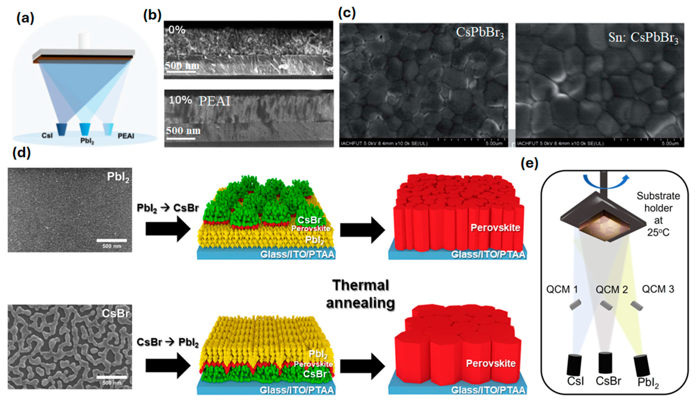
Figure 1. (a) Schematic representation of the vapor deposition process of γ-phase CsPbI3 perovskite film with PEAI and (b) scanning electron microscopic (SEM) cross-section images of CsPbI3 and 10% PEAI-containing CsPbI3, reproduced with permission, Creative Commons CC-BY-NC (2021), John Wiley and Sons. [17]. (c) SEM micrograph comparison of control CsPbBr3 and Sn: CsPbBr3 perovskite films deposited through the thermal evaporation method, reproduced with permission, CC BY-NC 3.0 (2021), Royal Society of Chemistry [18]. (d) Comparative illustration of deposition sequence to develop CsPbI2Br perovskite films through PbI2→CsBr and CsBr→PbI2 deposition, reproduced with permission, 2024, American Chemical Society [19]. (e) Graphical representation of the triple-source deposition process to fabricate CsPbI2Br perovskite films, reproduced with permission, Creative Commons CC-BY (2025), John Wiley and Sons [20].
Electronics 14 03171 g001
Figure 2. (a) Graphical representation of the stepwise procedure to fabricate CsPbBr3 perovskite films through the evaporation method, reproduced with permission, (2022) Elsevier [22]. (b) Pictorial representation of developing CsPbBr3 perovskite through the CVD method, reproduced with permission, (2023) Elsevier [23]. (c) Schematic illustration of stepwise fabrication of CsPbBr3 includes ball milling synthesis of CsPbBr3, further leading to close space sublimation and further deposition glass substrate, reproduced with permission, (2024) American Chemical Society [12]. (d) Three-step fabrication of CsPb(IxBr1−x)3 thin films through CFS and minor post-annealing, reproduced with permission, (2024) CC BY-NC 3.0 [24].
Electronics 14 03171 g002
Figure 3. (a) Reciprocal space map of CsPbIBr2 with symmetric peaks on lattice-matched SrTiO3 (001), (b) Uv-Vis absorption spectra of CsPb(IxClyBr1−x−y)3 perovskite films, reproduced with permission, (2022) AIP Publishing [19]. (c) Schematic illustration depicting the PLD of halide perovskites, starting with a dry mechanochemically synthesized mixture of stoichiometric precursors compacted into a solid PLD target, followed by laser ablation to deposit uniform thin films. (d,e) SEM cross-section images of MA1–xFAxPbI3 and MA1−xFAxPbI3(Cl)y thin films. (f) J–V curves of MA1−xFAxPbI3 and MA1−xFAxPbI3(Cl)y perovskite solar cells, reproduced with permission, (2024) Elsevier [20]. (g) Illustration of template-assisted PLD growth of CsxFA1−xPbI3 perovskite film deposited either on the template or directly on the substrate. (h,i) Cross-sectional SEM images of ITO//MeO-2PACz/CsxFA1−xPbI3 perovskites with and without template. (j) J–V curves of CsxFA1–xPbI3 on template perovskite solar cells at 0.01- and 0.1 cm2-cell area, reproduced with permission, (2025) CC BY license, John Wiley and Sons [21].
Electronics 14 03171 g003
Figure 4. (a,b) Comparative SEM micrographs of CsPbI2Br films deposited in PbI2→CsBr and CsBr→PbI2 sequences, reproduced with permission, 2024, American Chemical Society [19]. (c) Schematic representation of triple-junction perovskite/perovskite/Silicon tandem solar cell incorporating thermally evaporated CsPbI2Br perovskite as top layer. (d) Cross-sectional SEM image of triple-junction tandem device, reproduced with permission, Creative Commons CC-BY (2025), John Wiley and Sons [20]. (e) Comparative SEM images of CsPbBr3 deposited through vacuum co-evaporation and spin coating methods, reproduced with permission, (2021) Elsevier [34].
Electronics 14 03171 g004
Figure 5. (a) Comparative photoluminescence (PL) spectra of CsPbBr3 (without Sn) and Sn: CsPbBr3 perovskites, reproduced with permission, CC BY-NC 3.0 (2021), Royal Society of Chemistry [18]. Dark J-V characteristic curves (b) without CsBr and (c) with CsBr in hole-only device FTO/NiOx/CsPbI2Br/CuSCN/Au, reproduced with permission, (2022) American Chemical Society [35]. (d) SEM cross-sectional micrograph of PSC with CsPbBr3 photoabsorber. (e) Molecular structure of DTPT ionic liquid. (f) Time-resolved PL lifetime curves for CsPbBr3 without and with DTPT, reproduced with permission, (2023) CC BY-NC 3.0 [36].
Electronics 14 03171 g005
Figure 7. (a) J-V characteristic curves for CsPbBr3 PSCs without and with PEAI 10%, reproduced with permission, Creative Commons CC-BY-NC (2021), John Wiley and Sons. [17]. (b,c) Relative external quantum efficiency (EQE) and J-V characteristic curves for triple-junction tandem devices without and with F-PEAI passivation, reproduced with permission, Creative Commons CC-BY (2025), John Wiley and Sons [20]. (d) J-V curves for CsPbBr3 PSCs fabricated through spin coating and vacuum co-evaporation techniques, reproduced with permission, (2021) Elsevier [34]. (e) Comparative J-V characteristic curves of CsPbBr3 (without Sn) and Sn: CsPbBr3 PSCs, reproduced with permission, CC BY-NC 3.0 (2021), Royal Society of Chemistry [18]. (f) J-V characteristic curves for CsPbBr3 PSCs at 350 °C for different durations, reproduced with permission, (2022) Elsevier [22].
Electronics 14 03171 g007
Figure 8. (a,b) Grazing incidence X-ray diffraction (GIXRD) comparison of CsPbBr3 perovskite films fabricated through spin coating and vacuum deposition method. (c,d) Graphical representation of band energy alignment of rubrene with solution-processed CsPbBr3 and vacuum-processed CsPbBr3 perovskite, reproduced with permission, (2025) Elsevier [47]. (e) J-V characteristic curves of PSCs CsPbBr3-CuSCN (without CsBr and with CsBr), reproduced with permission, (2022) American Chemical Society [35]. (f) Pictorial representation of vapor deposition of CsPbBr3 perovskite arrays, reproduced with permission, (2024) Creative Commons CC BY [48].
Electronics 14 03171 g008
Table 2. Comparison of device parameters and device stability of PSCs containing inorganic perovskite photoabsorbers deposited through evaporation methods.
CompositionDeposition MethodPCE (%)AreaJsc mA cm−2Voc (V)FFStabilityRef.
γ-CsPbI3 + PEAICo-evaporation15.04.5 mm217.31.0979.4215 days
Encapsulated (RT)
[17]
CsPbI2BrSequential evaporation13.41~0.1 cm214.11.2079.1600 h
Without encapsulation (under N2 GB, 85 °C)
[19]
CsPbI2Br single-junction solar cellSequential evaporation7.71 cm210.61.0966.3100 h
Without encapsulation (RT), 35–40% RH
[20]
perovskite/perovskite/silicon
triple-junction tandem solar cell
21102.8374
CsPbBr3Co-evaporation9.430.04 cm29.771.3571.2480 h
Without encapsulation (RT), 40% RH
[34]
CsPbBr3 + DTPTCo-evaporation11.210.04 cm28.521.5783.6>100 days[36]
9.181 cm27.811.5077.8Without encapsulation (RT), 55% RH
Sn-CsPbBr3Direct evaporation8.950.09 cm29.271.3671.0720 h
Open-air environment
[18]
CsPbBr3E-beam7.810.06 cm26.811.4379.9Ambient stable[22]
α-CsxFA1-xPbI3Pulsed laser deposition14.00.01 cm220.270.9274.88Unencapsulated (stored under N2)
Measured/30–40% RH, 22 °C RT
[27]
12.910.1 cm219.430.9370.81
Disclaimer/Publisher’s Note: The statements, opinions and data contained in all publications are solely those of the individual author(s) and contributor(s) and not of MDPI and/or the editor(s). MDPI and/or the editor(s) disclaim responsibility for any injury to people or property resulting from any ideas, methods, instructions or products referred to in the content.