Article

Improvement of Tracking-Integrated Photovoltaic Systems Using Secondary Optical Elements

by
Maria A. Ceballos
1,*,
Pedro Perez-Higueras
1,
Katie Shanks
2,
Jesus Montes-Romero
1,
Alvaro Valera
1,
Florencia Almonacid
1 and
Eduardo F. Fernández
1
1
Advances in Photovoltaic Technology (AdPVTech), CEACTEMA, University of Jaén, Las Lagunillas Campus, 23071 Jaén, Spain
2
Environment and Sustainable Institute (ESI), University of Exeter, Penryn Campus, Penryn TR10 9FE, UK
*
Author to whom correspondence should be addressed.
Electronics 2025, 14(16), 3175; https://doi.org/10.3390/electronics14163175 (registering DOI)
Submission received: 17 July 2025 / Revised: 1 August 2025 / Accepted: 8 August 2025 / Published: 9 August 2025
(This article belongs to the Special Issue Materials and Properties for Solar Cell Application)

Abstract

Concentrator photovoltaic systems with tracking-integrated offer an alternative to traditional concentrator photovoltaic systems by eliminating the need for conventional solar trackers, reducing costs, and opening up new market opportunities. This study explores different configurations of modules with tracking-integrated systems. The first setup includes a static bi-convex aspheric lens and a mobile triple-junction solar cell. The second setup adds a secondary optical element to these components. This study also compares two materials, PMMA and BK7. These systems have been simulated theoretically and measured experimentally in the laboratory. The experimental results obtained are similar to the theoretical ones, thus validating the design presented. In addition, a study of the annual energy generated by both configurations in different locations shows an annual energy gain of 14% when including secondary optics in module design. These results provide an idea of the advantage of including secondary optics in the system design under real operating conditions for different sites.

1. Introduction

Concentrator photovoltaic (CPV) technology is characterized by its ability to concentrate sunlight onto highly efficient solar cells [1,2]. A typical CPV system consists of a multi-junction (MJ) solar cell as the receiver [3]; a primary optical element (POE) [4,5] to concentrate the solar radiation; and often a secondary optical element (SOE) to improve the system’s angular tolerance and the radiation distribution on the receiver [6]. These optical elements allow the surface area of the expensive MJ solar cells to be reduced, and thus, limit the cost while allowing higher efficiency than single-junction cells [7].
CPV mainly exploits direct normal irradiance (DNI), so the use of solar trackers is crucial to maintain the optical orientation of the module [8,9]. However, these systems require large areas of land and constant maintenance to ensure their correct operation. Thus, these trackers are limiting their use on surfaces such as building roofs and in applications such as agrivoltaics [10], and also represent an increase in cost in CPV technology [11,12]. To overcome these limitations, the concept of tracking-integrated CPV (TICPV) has been proposed [13]. It consists of incorporating the tracking elements within the CPV module itself, thus removing the need for external structures.
Among the systems developed, internal tracking has shown the greatest potential so far. However, most of the developed systems within the literature [14,15,16] do not integrate the SOE in their design. There are only two published works where an SOE is included in TICPV modules. In the case of Nardin et al.’s work [17], the possibility of including an SOE, a glass half-ball lens, to increase the angular tolerance to the possible errors caused in the manufacturing of the systems is considered. Nevertheless, the results presented in this study apparently do not show that they are related to using SOE, nor an improvement in performance. The study by Nakatani [18] is the only one that incorporates SOE and analyzes the optical improvement of the system with such additional optics. In this study, focused on optical efficiency (ηopt), a value of 77.5% is reached at normal incidence and over 60% for an angle of incidence (AOI) of 70°.
This work presents a detailed performance analysis of a CPV system enhanced with a tracking-integrated SOE. Two configurations have been developed and compared (see Figure 1): one without SOE (module #1) and one with SOE (module #2). Also, two materials, polymethylmethacrylate (PMMA) and BK7, are compared to evaluate the impact of material properties on the system’s performance. This study combines a theoretical analysis and an experimental characterization of the modules. The obtained results facilitate the performance evaluation of the proposed design, showing its feasibility and effectiveness under experimental conditions. This experimental validation supports the results of the theoretical simulations and validates the accuracy of the developed model. Additionally, an estimation of the annual energy gain generated by the modules in five locations with different irradiation conditions has been carried out. This allows the evaluation of the potential performance under different climatic conditions.
The results derived from this study are novel in this field. It provides information that improves TICPV systems and makes this type of PV technology competitive with other alternatives in the PV field.
This paper is structured as follows. Section 2 describes the system design and the methodology for performing the optical analysis. Section 3 presents the results of the optical analysis and energy gain at given locations. Finally, Section 4 provides the conclusions of the study, as well as considerations for future work.

2. Materials and Methods

This section describes the materials and methods used for the design and optimization of the optical elements for the TICPV system. The approach used to optimize the geometry of the POE and SOE is presented, aiming to improve the optical performance and angular tolerance of the system. The methodology used for the optical simulations is detailed, including the use of ray tracing software TracePro 25.2 (Lambda Research Corporation, Westford, MA, USA), as well as the calculations required to evaluate the key optical parameters of the system.
The module #1 is composed of a biconvex aspheric lens for the POE and a 3J solar cell. Module #2 is composed of a biconvex aspheric lens; a dome-shaped SOE; and a 3J solar cell (shown in Figure 1). The direct radiation reaching the biconvex aspheric lens is concentrated at its focal point, where the SOE entrance is located. As the AOI increases, the point shifts its position. The SOE, along with the cell, moves both laterally and vertically to follow the displacement of the concentrated radiation. In this configuration, the SOE geometry chosen is dome-shaped because a flat input surface [19,20,21,22], above a certain AOI, presents considerable losses due to reflection. Therefore, these higher losses result in a noticeable decrease in the ηopt of the system.
In this study, the POE and SOE are optimized to determine the optimal geometry of both optical elements. The objective is to achieve a concentrator system with high optical performance and high angular tolerance. The geometric concentration (Cg = APOE/Acell, with APOE representing the area of the POE surface, and Acell representing the area of the cell surface) considered is 10x. The optimization process carried out has been previously described [16] and is not the focus of this study.
To evaluate the impact that the chosen material has on the performance of the module, PMMA and BK7 are compared. Other materials that can be considered in the design of the optics are those that exhibit high transmittance within the wavelength range corresponding to the spectral response of the MJ cell. Some examples are polydimethylsiloxane (PDMS) or fused silica. However, this study focuses exclusively on PMMA and BK7 as they are the most commonly used and well-characterized materials in CPV systems [23,24]. In addition, these materials have a long service life and their degradation is acceptable [25,26].
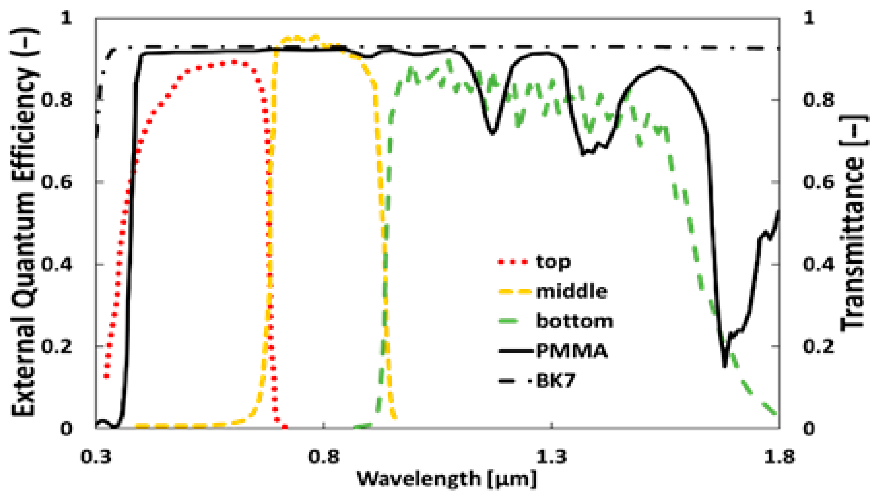
For the two chosen materials, the absorption coefficients and refractive index of PMMA have been obtained from the literature [27,28], while the corresponding values for BK7 come from the manufacturer SCHOTT (Duryea, PA, USA) [29] (see Figure 2).
A typical 3J solar cell (GaInP/GaInAs/Ge) with a 10 mm width is used in this study. The characteristics of this cell have been provided by AZUR SPACE Solar Power GmbH [30]. The External Quantum Efficiency (EQE) of the 3J solar cell is shown in Figure 2.
The AOI of the radiation value is one of the conditions taken into account to optimize the optical elements. In this case, for the optimization process, an AOI of 11.237° is considered. This value corresponds to the AOI range where we find the elevation of the sun most of the time.
Once the optimal geometry for each configuration is obtained (see Table 1), optical simulations are carried out using TracePro 25.2 raytracing software, considering the Concentration Standard Test Conditions (CSTCs): 1000 W/m2, 25 °C temperature, and AM1.5D reference spectrum defined in the range from 0.3 to 2.5 µm [31]. Also, the angular size of the sun (0.27°) is considered. This model takes into account the transmittance and angular properties of the elements of the CPV system as seen in Figure 2. Further information about the model and its experimental validation is available in previous work [32].
Based on the output characteristics of the optical modeling of the developed CPV system, the short-circuit current density (Jsc) is obtained from the EQE data of the cell as follows:
J s c , i = S R i λ · E λ · d λ = q h · c E Q E i λ · E λ · λ · d λ
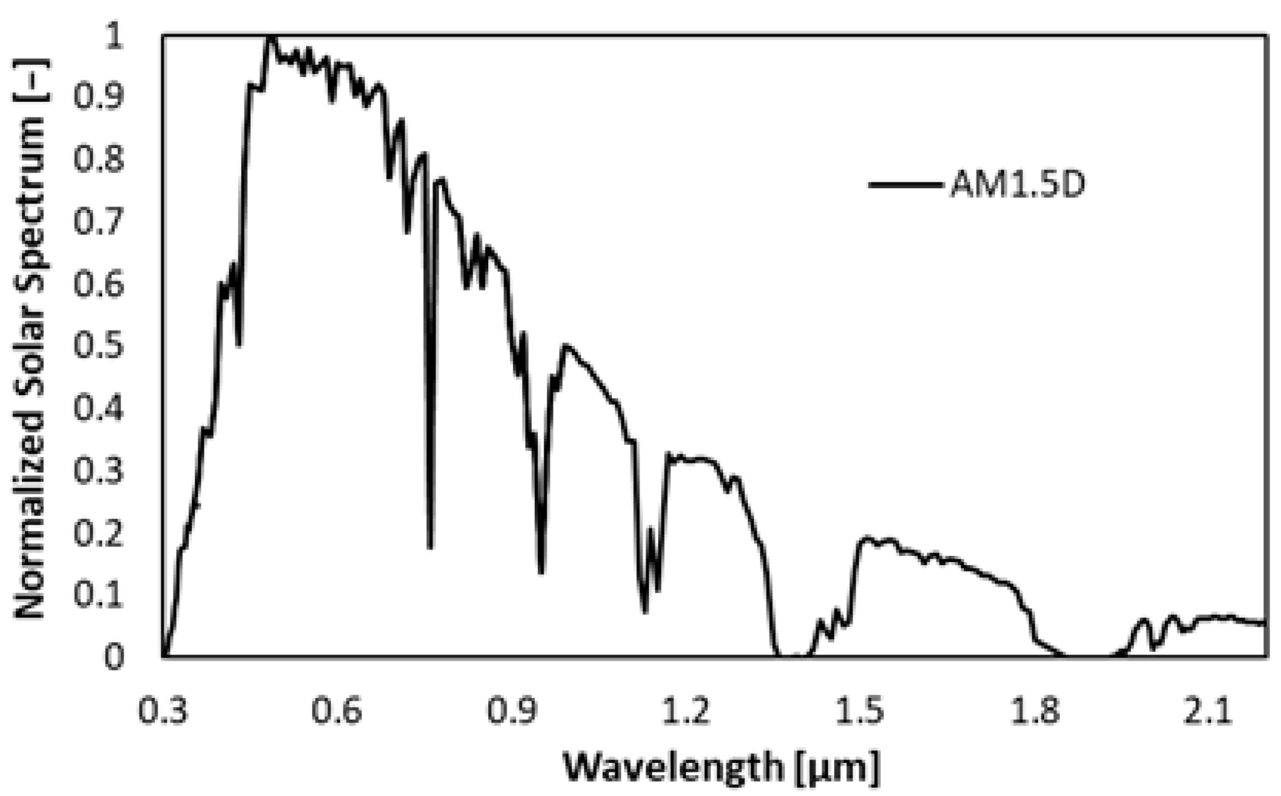
where “i” is the subscript referring to each subcell; q is the electric charge (q = 1.6∙10−19 C); h is Planck’s constant (h = 6.626∙10−34 J∙s); c is the speed of light in a vacuum (c = 3∙108 m/s); and E( λ ) is the spectral irradiance (see Figure 3) impinging on the solar cell simulated through ray tracing.
After obtaining the Jsc,i values for each subcell, the ηopt of the system is calculated as a function of the AOI [33]:
η o p t = 1 C g · min { J s c , t o p c o n c , J s c , m i d c o n c , J s c , b o t c o n c } min { J s c , t o p 1 s u n , J s c , m i d 1 s u n , J s c , b o t 1 s u n } · 1 c o s ( A O I )
where J s c c o n c is the value of the short-circuit current density under concentrated sunlight and J s c 1 s u n represents the values measured at 1 sun (1000 W/m2). For this specific cell, J s c , t o p   1 s u n = 15.6 mA/cm2; J s c , m i d 1 s u n = 15.7 mA/cm2; and J s c , b o t 1 s u n = 19.2 mA/cm2. Since the subcells of an MJ cell are connected in series, the overall Jsc is provided by the subcell with the minimum current. The cosine correction factor takes into account the decrease in the illumination area of the CPV modules with the AOI due to their fixed position.
The Spectral Matching Ratio (SMR) is also determined from the Jsc parameters of each subcell as follows [34,35]:
S M R t o p m i d d l e = J s c , t o p c o n c J s c , t o p 1 s u n J s c , m i d c o n c J s c , m i d 1 s u n
A value of SMR = 1 represents the spectral condition equivalent to the reference spectrum, where top and middle subcells usually generate the same current (current-matching condition). The case SMR < 1 refers to a red-rich spectrum, where the current is limited by the top subcell. While SMR > 1 refers to a blue-rich spectrum, where the current is limited by the middle subcell.

3. Analysis of the Results

Once the geometry of the optical elements has been optimized, simulations of both modules are carried out by ray tracing. The optical simulation of the design was subjected to experimental validation in a previous study [16]. The design analysis covers an AOI range of ±90°.
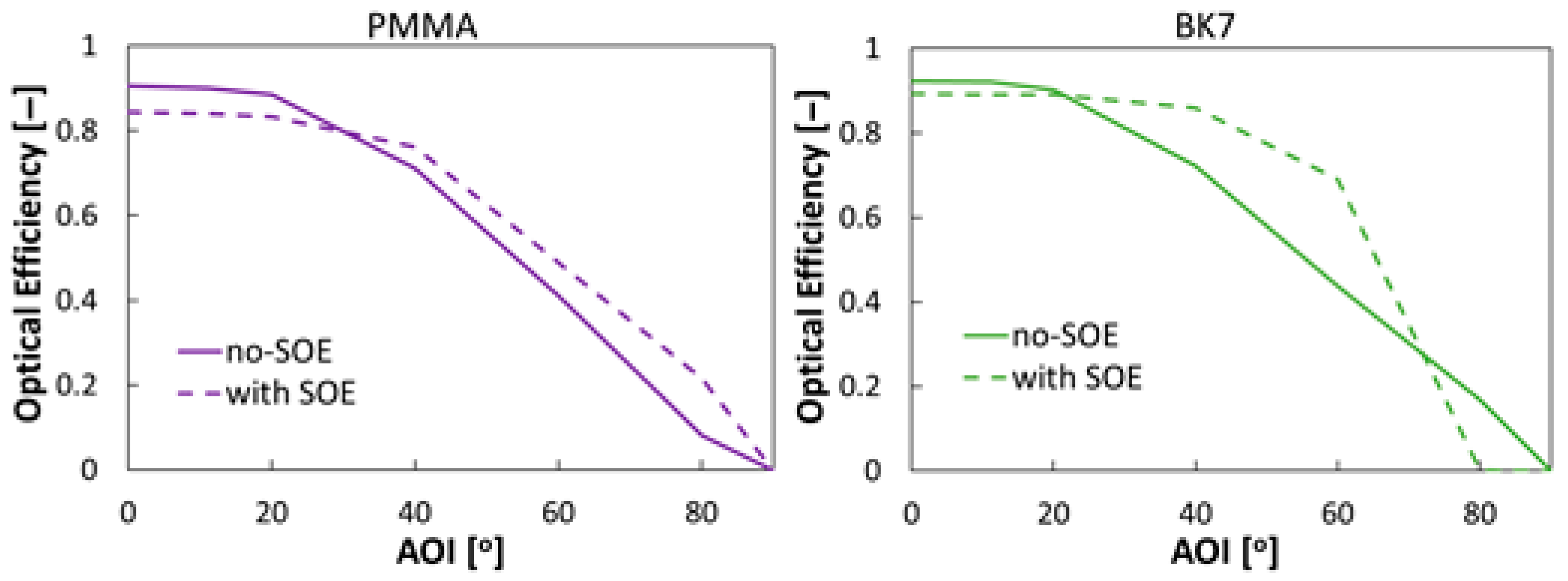
From the J s c c o n c value simulated and examining the ηopt results in Figure 4, a decreasing trend is observed as the AOI increases. This decrease is generalized for both module #1 and module #2, as well as for both materials. The decrease in ηopt as the AOI increases is due to several losses, as discussed in another study [16]. These are mainly dominated by reflection losses on the top face of the lens as a consequence of the curvature of the faces. This occurs in addition to other optical losses, such as non-focusing losses of the concentrated radiation on the solar cell at higher AOIs.
The inclusion of SOE in the design improves the results for both materials. This improvement is especially noticeable for BK7, with an ηopt value of 70% for an AOI of 60°. Without SOE, this value drops below 50%. In the case of PMMA and for the same AOI, the module with SOE achieves an ηopt value of 50%, compared to 40% for the module without SOE. Although the inclusion of an additional optic shows an improvement in the ηopt value for PMMA, it is less significant compared to that of BK7.
Under normal incidence conditions (AOI = 0°), the result is different. Module #1 reaches an ηopt of 90.6% and 92.3% for PMMA and BK7, respectively. The ηopt is slightly higher for BK7 due to its higher transmittance (see Figure 2). When SOE is included, the ηopt at normal incidence decreases by 6% for PMMA to a value of 84.5%, and a decrease of 3% occurs for BK7 with an ηopt value of 89.3%.
The SOE introduces additional absorption and reflection losses, as evidenced by a decrease in ηopt in the module, especially at low AOIs. However, the SOE improves the focusing of rays on the cell surface. Because of this, the non-focusing losses are reduced due to the higher angular tolerance of the system for high AOIs. Moreover, compared to the design proposed by Nakatani [18], the values obtained represent an improvement in ηopt of 7% for the PMMA module and 12% for the BK7 module.
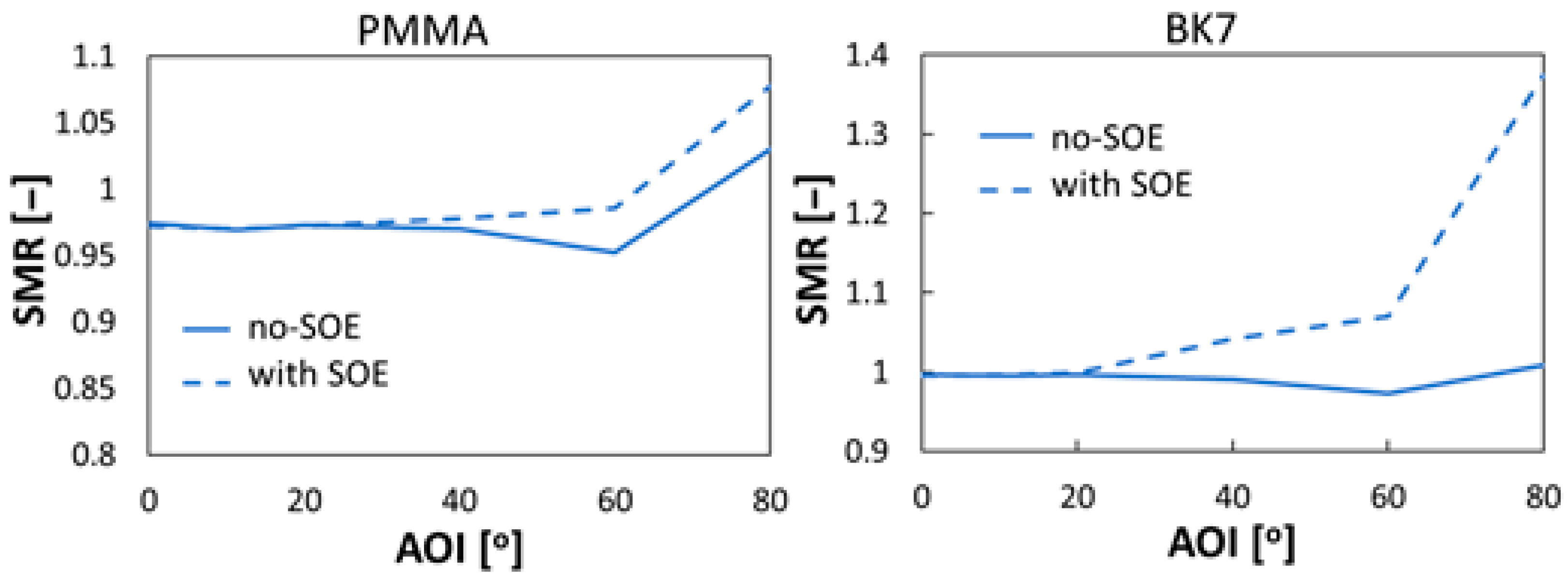
Spectral losses are also caused by the modification of the input spectrum on the cell due to the non-uniform optical path length of the rays. Figure 5 shows the spectral differences between the two CPV units and both materials.
For the system designed with PMMA, the module without SOE achieves an average SMR value of 0.978. When including SOE, this average value reaches an SMR of 0.999. These values are close to unity and indicative of minimal spectral losses, even with the inclusion of additional optics.
In the case of the system designed with BK7, the average SMR value is 0.994 for the module without SOE. By including the SOE, the SMR achieves an average value of 1.079. This implies that the inclusion of the SOE with the BK7 material increases spectral losses with respect to the case of not including it. The most significant losses occur from an AOI of 60°. Despite this, the design using BK7 remains the best option. It features an SMR value close to unity over a wider AOI range.
In addition to the simulations, an experimental investigation was carried out. In this case, only the system designed with PMMA was considered due to its greater ease of fabrication. The POE and SOE were manufactured by the company Prodicex Solutions S.L. (Coruna, Spain). The 3J solar cell is the one mentioned above for the simulations.
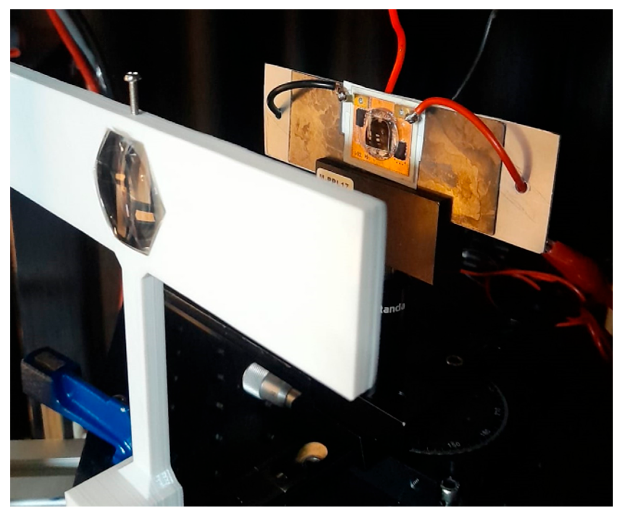
The experimental characterization of the two configurations was performed in the indoor test laboratory of the Center for Advances Studies in Earth Sciences, Energy and Environmental (CEACTEMA), University of Jaén. The CPV solar simulator used was “Helios 3198”, which is used in various other studies that provide details of its capability [36]. The modules were placed on the supporting structure of the solar simulator and aligned to the direct incident irradiance, as seen in Figure 6. Since this simulator keeps the direction of the collimated beam fixed, a rotating optomechanical component can be used to rotate the CPV module and thus emulate the apparent motion of the source. The cell is moved manually in two directions by means of rails, to track the displacement of the concentrated light spot.
The I-V characteristics of the module were obtained under conditions equivalent to CSTC, maintaining an ambient room temperature of 25 °C, and adjusting the irradiance and controlling the spectrum with the component solar cells (SMRs~1) [34]. The measurements were performed several times for each configuration in order to quantify the uncertainty of the experimental characterization. Table 2 shows the standard deviation values for the module without SOE and the module with SOE. As can be seen, the methodology used has a low level of error, which is a good indicator of the repeatability and reliability of the process.
Analyzing the data obtained, Figure 7 shows a comparison between the values obtained from the ray-tracing optical simulations and those measured in the laboratory for both cases. The ηopt results exhibit a trend similar to the simulations in the case of the system without SOE, although with lower values. This may be caused by defects introduced during lens manufacturing, misalignments in cell positioning as the AOI increases, and additional absorption and reflection losses. For the system with SOE, it can be observed that, for the lowest and highest AOI values, the measured results are almost identical to the simulated ones. However, between 40° and 60°, a greater discrepancy was observed, which may be mainly associated with losses caused by air bubbles that appeared when attaching the SOE to the cell with the optical adhesive.
Nevertheless, these results can be considered acceptable, validating the proposed design and supporting the incorporation of an SOE as a strategy to improve the performance of tracking-integrated CPV systems.
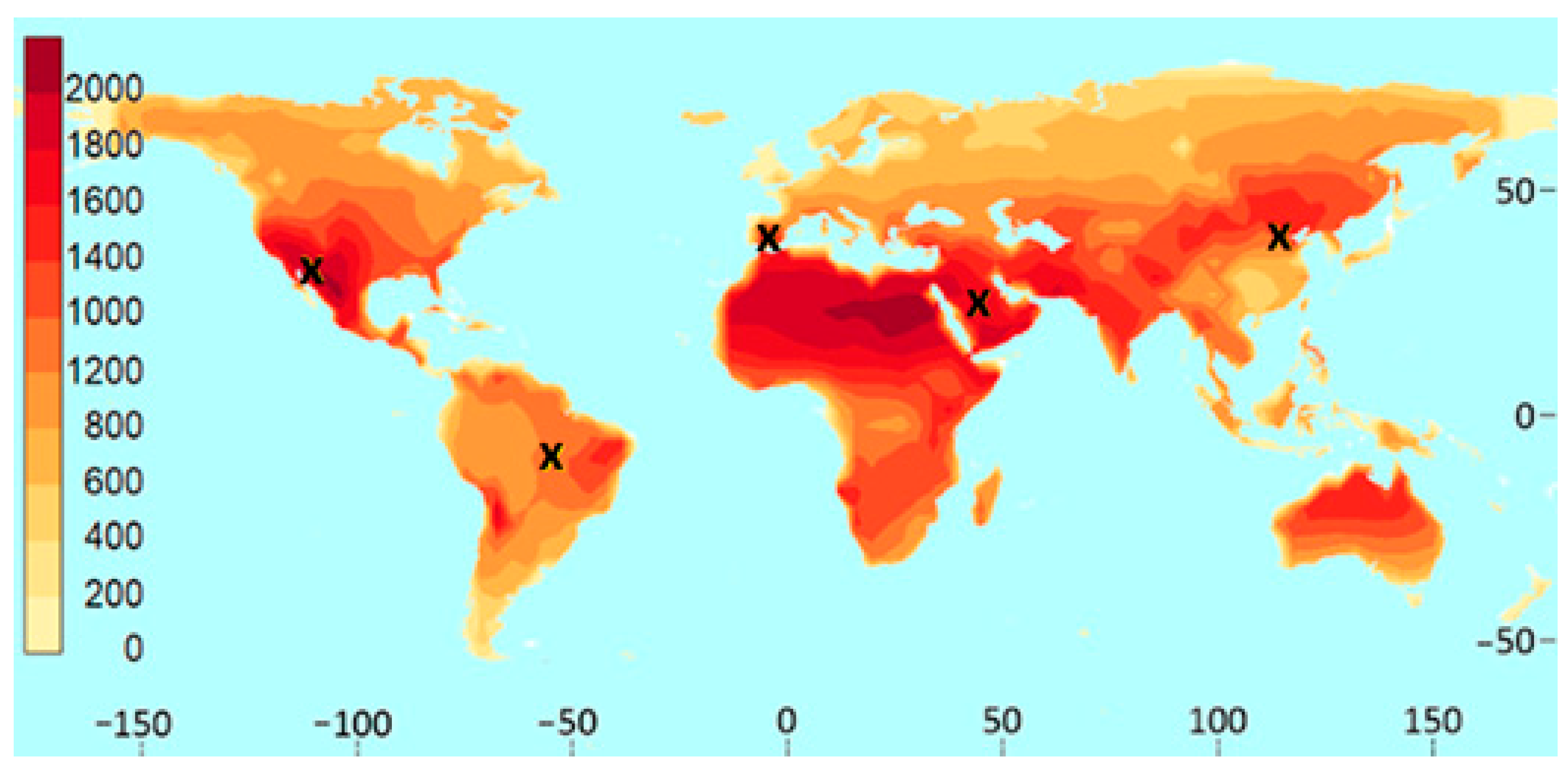
This study also determines the annual energy gain implied by the inclusion of SOE in system design. For this purpose, five sites with medium-to-high annual direct inclined irradiation (DII) values and different spectral characteristics were selected. These five locations can be considered representative of areas where TICPV systems are competitive. The locations are Jaén (Spain), with an annual DII of 1603 kWh/m2; Alta Floresta (Brazil), with an annual DII of 1275 kWh/m2; Santa Ana (México), with an annual DII of 1984.59 kWh/m2; Beijing (China), with an annual DII of 1338 kWh/m2; and Solar Village (Saudi Arabia), with an annual DII of 1984 kWh/m2. Figure 8 shows these five sites and their different levels of annual DII. This annual DII map was developed by Perez-Higueras et al. [37].
The meteorological data for each location were obtained from the Typical Meteorological Year (TMY), provided by the PVGIS database. Using Fernandez et al.’s expression of developed power [38] and the ηopt values determined experimentally in the laboratory, the cell efficiency, temperature coefficient, and other relevant parameters (e.g., inverter efficiency) enabled the annual energy generated by the system to be estimated at each location.
In the experimental design that incorporates PMMA, the inclusion of the SOE system achieved average energy gains close to 14% for the five scenarios analyzed. Table 3 shows the annual energy values, as well as the gains obtained. These results show that the use of SOE leads to a clear improvement in terms of energy performance, regardless of the climatic spectral difference in the sites.

4. Conclusions

This study provides a comprehensive evaluation of the inclusion of an SOE into tracking-integrated CPV systems, highlighting its impact on improving the optical performance and overall energy yield. The analysis, based on both ray-tracing simulations and experimental validation, demonstrates that the inclusion of an SOE can significantly improve the angular tolerance of the module.
Although AOIs were close to normal, the use of an SOE in the design implies a slight reduction in the ηopt of the module; this decrease is compensated by a significant increase in ηopt from angles close to 40°. This allows for better performance over a wider angular range compared to the case without SOE.
The influence of the material on the ηopt of the module is also relevant. In particular, the use of BK7 glass enables superior performance compared to PMMA due to its higher transmittance and better angular response. This causes the module to have a higher ηopt over a wider range of AOIs. As a result, the BK7-based design is a more robust and efficient option under real-world solar tracking conditions, where angular variation is inevitable.
The experimental measurements conducted under controlled indoor conditions served to validate the simulated results, showing a strong correlation between both approaches and confirming the accuracy of the optical model. This consistency reinforces the reliability of the proposed design methodology and supports its applicability in the development of next-generation CPV systems.
In addition, an average energy gain of 14% was achieved for different geographical locations with different DII values, confirming the advantage of including SOE into the design.
In future work, a comparative study of the energy performance in different locations will identify areas where it is feasible to implement this technology and assess its competitiveness against other PV technologies under real operating conditions. A cost analysis will help to evaluate the benefits of these systems. Furthermore, alternative control and monitoring systems [39,40] based on devices not yet used in this system will be explored.

Author Contributions

M.A.C.: Conceptualization, methodology, formal analysis, investigation, and writing—original draft preparation. P.P.-H.: Writing—review and editing, visualization, formal analysis, funding acquisition, and supervision. K.S.: Supervision and writing—review and editing. A.V.: Writing—review and editing. J.M.-R.: Formal analysis and writing—review and editing. F.A.: Writing—review and editing, funding acquisition, and supervision. E.F.F.: Writing—review and editing, funding acquisition, and supervision. All authors have read and agreed to the published version of the manuscript.

Funding

This work is part of the project WiT-CPV, grant CNS2022-135288, founded by MICIU/AEI/10.13039/501100011033 and the European Union NextGenerationEU/PRTR.

Data Availability Statement

The data will be made available on request.

Conflicts of Interest

The authors declare no conflicts of interest.

Nomenclature

The following nomenclature is used in this manuscript:
Abbreviations
AOIAngle of incidence (°)
CPVConcentrator photovoltaic
CSTCsConcentrator standard test conditions
DIIDirect inclined irradiation
DNIDirect normal irradiance
EQEExternal quantum efficiency (−)
MJMulti-junction
PMMAPoly(methylmethacrylate)
POEPrimary optical element
PVPhotovoltaic
SMRSpectral matching ratio
SOESecondary optical element
TICPVTracking-integrated concentrator photovoltaic
TMYTypical meteorological year
Parameters
AcellArea of the cell (mm2)
APOEArea of the POE (mm2)
CgGeometric concentration (x)
JSCShort-circuit current density (A/m2)
ηoptOptical efficiency (%)

References

  1. Khamooshi, M.; Salati, H.; Egelioglu, F.; Hooshyar Faghiri, A.; Tarabishi, J.; Babadi, S. A Review of Solar Photovoltaic Concentrators. Int. J. Photoenergy 2014, 1, 958521. [Google Scholar] [CrossRef]
  2. Geisz, J.F.; France, R.M.; Schulte, K.L.; Steiner, M.A.; Norman, A.G.; Guthrey, H.L.; Young, M.R.; Song, T.; Moriarty, T. Six-Junction III–V Solar Cells with 47.1% Conversion Efficiency under 143 Suns Concentration. Nat. Energy 2020, 5, 326–335. [Google Scholar] [CrossRef]
  3. Doeleman, H. Limiting and Realistic Efficiencies of Multi-Junction Solar Cells; Photonic Materials Group: Amsterdam, The Netherlands, 2012. [Google Scholar]
  4. Shanks, K.; Senthilarasu, S.; Mallick, T.K. Optics for Concentrating Photovoltaics: Trends, Limits and Opportunities for Materials and Design. Renew. Sustain. Energy Rev. 2016, 60, 394–407. [Google Scholar] [CrossRef]
  5. Iqbal, W.; Ullah, I. Optical Developments in Concentrator Photovoltaic Systems—A Review. Sustainability 2023, 15, 10554. [Google Scholar] [CrossRef]
  6. Victoria, M.; Domínguez, C.; Antón, I.; Sala, G. Comparative Analysis of Different Secondary Optical Elements for Aspheric Primary Lenses. Opt. Express 2009, 17, 6487–6492. [Google Scholar] [CrossRef] [PubMed]
  7. Luque, A.; Sala, G.; Luque-Heredia, I. Photovoltaic Concentration at the Onset of Its Commercial Deployment. Prog. Photovoltaics Res. Appl. 2006, 14, 413–428. [Google Scholar] [CrossRef]
  8. Chemisana, D. Building Integrated Concentrating Photovoltaics: A Review. Renew. Sustain. Energy Rev. 2011, 15, 603–611. [Google Scholar] [CrossRef]
  9. Paliyal, P.S.; Mondal, S.; Layek, S.; Kuchhal, P.; Pandey, J.K. Automatic Solar Tracking System: A Review Pertaining to Advancements and Challenges in the Current Scenario. Clean Energy 2024, 8, 237–262. [Google Scholar] [CrossRef]
  10. Trommsdorff, M.; Campana, P.E.; Macknick, J.; Fernández Solas, A.; Gorjian, S.; Tsanakas, I. Dual Land Use for Agriculture and Solar Power Production: Overview and Performance of Agrivoltaic Systems; International Energy Agency: Paris, France, 2025; ISBN 9783907281703. [Google Scholar]
  11. Algora, C.; Rey-Stolle, I. Handbook on Concentrator Photovoltaic Technology; Wiley: Hoboken, NJ, USA, 2016; ISBN 9781118755631. [Google Scholar]
  12. Kalogirou, S. McEvoy’s Handbook of Photovoltaics: Fundamentals and Applications, 3rd ed.; Academic Press: New York, NY, USA, 2018; ISBN 978-0-12-809921-6. [Google Scholar]
  13. Ceballos, M.A.; Pérez-Higueras, P.J.; Fernández, E.F.; Almonacid, F. Tracking-Integrated CPV Technology: State-of-the-Art and Classification. Energies 2023, 16, 5605. [Google Scholar] [CrossRef]
  14. Price, J.S.; Sheng, X.; Meulblok, B.M.; Rogers, J.A.; Giebink, N.C. Wide-Angle Planar Microtracking for Quasi-Static Microcell Concentrating Photovoltaics. Nat. Commun. 2015, 6, 6223. [Google Scholar] [CrossRef]
  15. Ito, A.; Sato, D.; Yamada, N. Optical Design and Demonstration of Microtracking CPV Module with Bi-Convex Aspheric Lens Array. Opt. Express 2018, 26, A879. [Google Scholar] [CrossRef]
  16. Ceballos, M.A.; Valera, Á.; Sanmartín, P.; Almonacid, F.; Fernández, E.F. Development and Indoor Characterization of a Concentrator Photovoltaic Assembly for Tracking-Integrated Systems. Sol. Energy 2023, 255, 292–300. [Google Scholar] [CrossRef]
  17. Nardin, G.; Domínguez, C.; Aguilar, Á.F.; Anglade, L.; Duchemin, M.; Schuppisser, D.; Gerlich, F.; Ackermann, M.; Coulot, L.; Cuénod, B.; et al. Industrialization of Hybrid Si/III–V and Translucent Planar Micro-tracking Modules. Prog. Photovoltaics Res. Appl. 2021, 29, 819–834. [Google Scholar] [CrossRef]
  18. Nakatani, M. Calculation of the Interaction between an Overlapping Spherical Lens and a Pin-Type Second Optical Element for Spherical Lens Microtracking Concentrator Photovoltaic with a Wide Angle of Incidence. Jpn. J. Appl. Phys. 2024, 63, 052002. [Google Scholar] [CrossRef]
  19. O’Gallagher, J.J. Nonimaging Optics in Solar Energy; Morgan & Claypool Publishers: San Rafael, CA, USA, 2008; ISBN 9781598293302. [Google Scholar]
  20. Cooper, T.; Dähler, F.; Ambrosetti, G.; Pedretti, A.; Steinfeld, A. Performance of Compound Parabolic Concentrators with Polygonal Apertures. Sol. Energy 2013, 95, 308–318. [Google Scholar] [CrossRef]
  21. Fu, L.; Leutz, R.; Annen, H.P. Secondary Optics for Fresnel Lens Solar Concentrators. Nonimaging Opt. Effic. Des. Illum. Sol. Conc. VII 2010, 7785, 778506–778509. [Google Scholar] [CrossRef]
  22. Reddy, K.S.; Mallick, T.K.; Srihari Vikram, T.; Sharon, H. Design and Optimisation of Elliptical Hyperboloid Concentrator with Helical Receiver. Sol. Energy 2014, 108, 515–524. [Google Scholar] [CrossRef]
  23. Ramachandran, A.M.; S, S.M.; Thampi, A.S.; Singh, M.; Asok, A. A Comprehensive Review on Optics and Optical Materials for Planar Waveguide-Based Compact Concentrated Solar Photovoltaics. Results Eng. 2022, 16, 100665. [Google Scholar] [CrossRef]
  24. El Himer, S.; El Ayane, S.; El Yahyaoui, S.; Salvestrini, J.P.; Ahaitouf, A. Photovoltaic Concentration: Research and Development. Energies 2020, 13, 5721. [Google Scholar] [CrossRef]
  25. Miller, D.C.; Khonkar, H.I.; Herrero, R.; Antón, I.; Johnson, D.K.; Hornung, T.; Schmid-Schirling, T.; Vinzant, T.B.; Deutch, S.; To, B.; et al. An End of Service Life Assessment of PMMA Lenses from Veteran Concentrator Photovoltaic Systems. Sol. Energy Mater. Sol. Cells 2017, 167, 7–21. [Google Scholar] [CrossRef]
  26. Miller, D.C.; Kurtz, S.R. Durability of Fresnel Lenses: A Review Specific to the Concentrating Photovoltaic Application. Sol. Energy Mater. Sol. Cells 2011, 95, 2037–2068. [Google Scholar] [CrossRef]
  27. Miller, D.C.; Kempe, M.D.; Kennedy, C.E.; Kurtz, S.R. Analysis of Transmitted Optical Spectrum Enabling Accelerated Testing of Multijunction Concentrating Photovoltaic Designs. Opt. Eng. 2011, 50, 13003. [Google Scholar] [CrossRef]
  28. Beadie, G.; Brindza, M.; Flynn, R.A.; Rosenberg, A.; Shirk, J.S. Refractive Index Measurements of Poly(Methyl-Methacrylate) (PMMA) from 0.4–1.6μm. Appl. Opt. 2015, 54, F139–F143. [Google Scholar] [CrossRef] [PubMed]
  29. SCHOTT Optical Glass Data Sheets; SCHOTT North America, Inc.: Duryea, PA, USA, 2014.
  30. AzurSpace Concentrator Triple Junction Solar Cell. Cell Type: 3C44. Application: Concentrating Photovoltaic (CPV) Modules. Available online: https://www.azurspace.com/images/products/0004355-00-01_3C44_AzurDesign_10x10.pdf (accessed on 1 May 2025).
  31. IEC 62670-1:2013; Photovoltaic Concentrators (CPV)—Performance Testing—Part 1: Standard Conditions. IEC: Geneva, Switzerland, 2013.
  32. Ferrer-Rodríguez, J.P.; Baig, H.; Fernández, E.F.; Almonacid, F.; Mallick, T.; Pérez-Higueras, P. Optical Modeling of Four Fresnel-Based High-CPV Units. Sol. Energy 2017, 155, 805–815. [Google Scholar] [CrossRef]
  33. Benítez, P.; Miñano, J.C.; Zamora, P.; Mohedano, R.; Cvetkovic, A.; Buljan, M.; Chaves, J.; Hernández, M. High Performance Fresnel-Based Photovoltaic Concentrator. Opt. Express 2010, 18, A25–A40. [Google Scholar] [CrossRef]
  34. Domínguez, C.; Antón, I.; Sala, G.; Askins, S. Current-Matching Estimation for Multijunction Cells within a CPV Module by Means of Component Cells. Prog. Photovolt Res. Appl. 2013, 21, 1478–1488. [Google Scholar] [CrossRef]
  35. Núñez, R.; Jin, C.; Antón, I.; Sala, G. Spectral Classification of Worldwide Locations Using SMR Indexes. AIP Conf. Proc. 2016, 1766, 90007-1. [Google Scholar] [CrossRef]
  36. Domínguez, C.; Askins, S.; Antón, I.; Sala, G. Characterization of Five CPV Module Technologies with the Helios 3198 Solar Simulator. In Proceedings of the 2009 34th IEEE Photovoltaic Specialists Conference (PVSC), Philadelphia, PA, USA, 7–12 June 2009; pp. 1004–1008. [Google Scholar] [CrossRef]
  37. Perez-Higueras, P.; Ceballos, M.A.; Mouhib, E.; Bessa, J.G.; Montes-Romero, J.; Mata-Campos, R. Comparative Analysis of Direct Inclined Irradiance Data Sources for Micro-Tracking Concentrator Photovoltaics. Electron. 2025, 14, 2297. [Google Scholar] [CrossRef]
  38. Fernández, E.F.; Talavera, D.L.; Almonacid, F.M.; Smestad, G.P. Investigating the Impact of Weather Variables on the Energy Yield and Cost of Energy of Grid-Connected Solar Concentrator Systems. Energy 2016, 106, 790–801. [Google Scholar] [CrossRef]
  39. Su, L. Room Temperature Growth of CsPbBr3 Single Crystal for Asymmetric MSM Structure Photodetector. J. Mater. Sci. Technol. 2024, 187, 113–122. [Google Scholar] [CrossRef]
  40. Xia, Z.; Chen, Y.; Su, L.; Chen, H. Bioinspired Artificial Optoelectronic Synapse for Encrypted Communication Realized via a MoSe 2 Based MIS Structural Photodiode. J. Mater. Sci. Technol. 2026, 243, 129–138. [Google Scholar] [CrossRef]
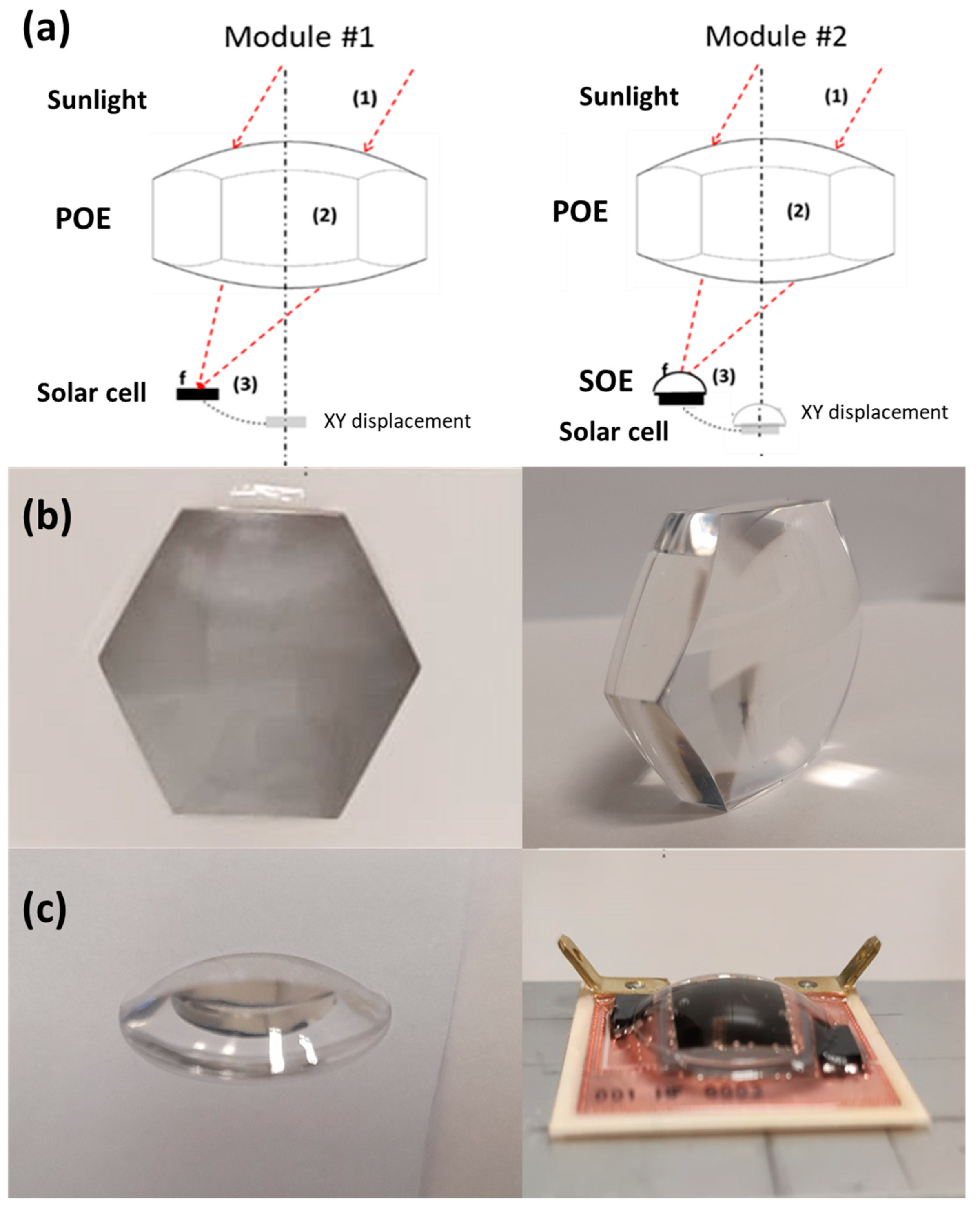
Figure 1. (a) Schematic of the TICPV module without SOE (left) and with SOE (right), showing the ray tracing and the XY displacement of the solar cell: (1) Incident radiation; (2) POE; (3) focal point where the cell (or SOE and cell) is located. (b) The front and side views of the POE fabricated for experimental measurements. (c) Left: The side view of the SOE fabricated for experimental measurements. Right: The integration of the SOE with the solar cell.
Electronics 14 03175 g001
Figure 2. External Quantum Efficiency (EQE) of the 3-junction solar cell and transmittance of the PMMA material and the BK7 material.
Electronics 14 03175 g002
Figure 3. Normalized solar spectrum (E(λ)) AM1.5D.
Electronics 14 03175 g003
Figure 4. The value of ηopt as a function of AOI obtained by ray tracing. A comparison between the tracking integrated system without SOE and the tracking integrated system with SOE. PMMA and BK7 materials were used in the design.
Electronics 14 03175 g004
Figure 5. Simulated SMR values for the two optical units. Evolution under the corresponding AOI with respect to incident solar rays for PMMA and BK7 materials.
Electronics 14 03175 g005
Figure 6. An experimental setup composed of a biconvex aspheric lens, dome-shaped SOE, and 3J solar cells measured in the Helios 3198 solar simulator.
Electronics 14 03175 g006
Figure 7. The ηopt comparison between simulations and indoor measurements of the system without SOE and the system with SOE.
Electronics 14 03175 g007
Figure 8. The annual DII (kWh/m2·year) (based on [37]), showing the location (x) of the sites selected to evaluate the energy gain of a system without SOE vs. a system with SOE.
Electronics 14 03175 g008
Table 1. An overview of the features of the CPV modules without SOE and with SOE obtained through the optimization process for two materials.
PMMABK7
No-SOESOENo-SOESOE
POE Lens diagonal [mm]39.2439.2439.2439.24
POE Focal length [mm]5436.54130.5
POE Thickness [mm]12.521.516.4525.2
Dome-Shaped SOE Radius of Curvature [mm−1]-0.095-0.095
Table 2. The standard deviation of the main electrical parameters measured for the system with no SOE and the system with SOE.
Electrical ParametersNo SOEWith SOE
VSC±0.72%±0.58%
ISC±0.21%±0.17%
Pmp±0.39%±0.42%
Vmp±1.03%±1.56%
Imp±0.16%±0.17%
Table 3. The energy gain of a system with SOE vs. without SOE for five selected locations.
JaénAlta FlorestaSolar VillageSanta AnaBeijing
Latitude37.7797° N9.8797° S24.7743° N30.542° N40.191° N
Longitude3.7797° N56.0853° W46.7386° E111.121° S116.412° S
Annual energy no-SOE (kWh/m2∙year)305.12240.38342.61419.51283.55
Annual energy with SOE (kWh/m2∙year)348.26273.98389.48480.91323.34
Gain (%)14.1413.9813.6814.6414.03
Disclaimer/Publisher’s Note: The statements, opinions and data contained in all publications are solely those of the individual author(s) and contributor(s) and not of MDPI and/or the editor(s). MDPI and/or the editor(s) disclaim responsibility for any injury to people or property resulting from any ideas, methods, instructions or products referred to in the content.