Article

Design of an Energy Selective Surface Employing Dual-Resonant Circuit Topology

College of Electronic Science and Technology, National University of Defense Technology (NUDT), Changsha 410073, China
*
Author to whom correspondence should be addressed.
Electronics 2025, 14(15), 3029; https://doi.org/10.3390/electronics14153029
Submission received: 22 June 2025 / Revised: 23 July 2025 / Accepted: 25 July 2025 / Published: 30 July 2025
(This article belongs to the Section Microelectronics)

Abstract

A dual-polarization energy selective surface (ESS) with low insertion loss (IL) and high shielding effectiveness (SE) based on a dual-resonant equivalent circuit topology was proposed for high-intensity radiation field (HIRF) protection in this paper. The design principle was elucidated through an equivalent circuit model and translated into a physical ESS implementation. It consists of two resonant rings, vertically arranged and loaded with diodes, along with two lumped capacitors. Simulation and measurement results demonstrate that the IL is less than 3 dB when in the OFF state in a working frequency band, and the SE exceeds 20 dB when in the ON state. Moreover, the ESS’s dual-polarization, low cost, and easy-to-design characteristics hold great promise for broad applications in protecting communication and radar systems in complex electromagnetic environments.

1. Introduction

High-intensity radiation fields (HIRFs) refer to electromagnetic (EM) environments characterized by extremely high electric field strengths (typically exceeding 100 volts per meter) across a broad spectrum, ranging from extremely low frequencies to microwave bands [1,2,3]. Unlike narrowband signals, HIRFs may persist for microseconds to milliseconds, enabling prolonged interaction with vulnerable components [4,5,6]. In electronic systems, the energy of HIRFs can penetrate shell clearance, antennas, or cable interfaces, generating parasitic currents, voltage surges, or localized heating [7,8]. How to effectively restrain the harm of HIRFs to electronic information systems is becoming a hot topic [9,10,11]. Traditionally, the means of dealing with HIRF interference mostly adopt the way of a “back door” to protect the electronic system. However, HIRFs can still interfere with the electronic system through the “front door” way, where they can directly enter the electronic device through the antenna of the radar and receiver. The microwave energy acts directly on the key components of the electronic system, such as integrated circuits and semiconductor devices. When the incident energy reaches a certain level, it may interfere with or even burn these components, resulting in system breakdown.
To mitigate the intrusion of HIRFs through system interfaces through front doors, frequency selective surfaces (FSSs) [12,13,14], limiters, and energy selective surfaces (ESSs) have been developed [15,16,17]. In particular, ESS technology serves as a threshold-controlled energy filter [18,19,20]: it enables unimpeded transmission of low-power operational signals while autonomously triggering reflection/absorption mechanisms when exposed to high-intensity EM energy, thereby providing adaptive protection at electronic system front-ends [21].
In recent years, ESSs have been predominantly categorized into four distinct classes characterized by their operational mechanisms and structural topologies. PIN or Schottky diode-switched ESS designs are extensively implemented for dynamic band-pass/band-stop transitions [22,23,24,25], though constrained by inherent bandwidth limitations. Multilayer metallic configurations are engineered to achieve ultrawideband performance with shielding effectiveness (SE) exceeding 15 dB across extended frequency ranges [26,27], albeit at the cost of fabrication complexity. Nonlinear metasurface implementations enable waveform-selective responses that autonomously discriminate between operational signals and threats from HIRFs [28,29,30], while waveguide-integrated variants are developed for specialized enclosed-system protection [8,9]. Alternative approaches utilizing phase-change materials or plasma limiters [17,22,26,27] are investigated to overcome semiconductor limitations, though practical deployment remains challenged by stringent operational requirements. Diffusive and absorptive ESS architectures [15,31,32] further expand functional versatility beyond conventional transmission-blocking paradigms.
Conventional ESSs predominantly employ a single-resonant structure [15,33,34], which exhibits low-pass filtering characteristics in the transparent state and low-frequency blocking characteristics in the shielding state. Although the structure offers structural simplicity and straightforward design, it suffers from two fundamental limitations: the low-pass characteristic suffers from severely degraded insertion loss (IL) at high frequencies, and the low-frequency blocking characteristic suffers from compromised SE at the high frequency range.
To overcome these constraints, a dual-resonant equivalent circuit topology was adapted in this paper to enable dynamic switching between band-pass and band-stop characteristics. When the diode is switched on, the equivalent circuit model becomes a single-resonant circuit and presents band-stop characteristics. Then, according to the dual-resonant circuit topology, a periodic structure that meets the equivalent circuit was designed. Finally, the performance of the periodic structure was tested in the C-band through software simulation and waveguide injection measurement. The proposed ESS structure achieves simultaneous optimization of band-pass transmission (IL < 3 dB) and broadband protection (SE > 20 dB) within identical frequency ranges. Furthermore, the ESS’s dual-polarization, cost-effectiveness, and simple design make it highly promising for protecting communication systems in HIRFs.
This paper was arranged as follows. Section 1 established the EM protection challenges posed by HIRFs and reviews existing mitigation technologies. Section 2 detailed the dual-resonant circuit topology through theoretical analysis of impedance transformations enabling dynamic band-pass/stop switching. Section 3 comprehensively validated the design via simulations. Section 4 experimentally verified performance through waveguide injection testing. Finally, conclusions were drawn in Section 5.

2. Structure and Design

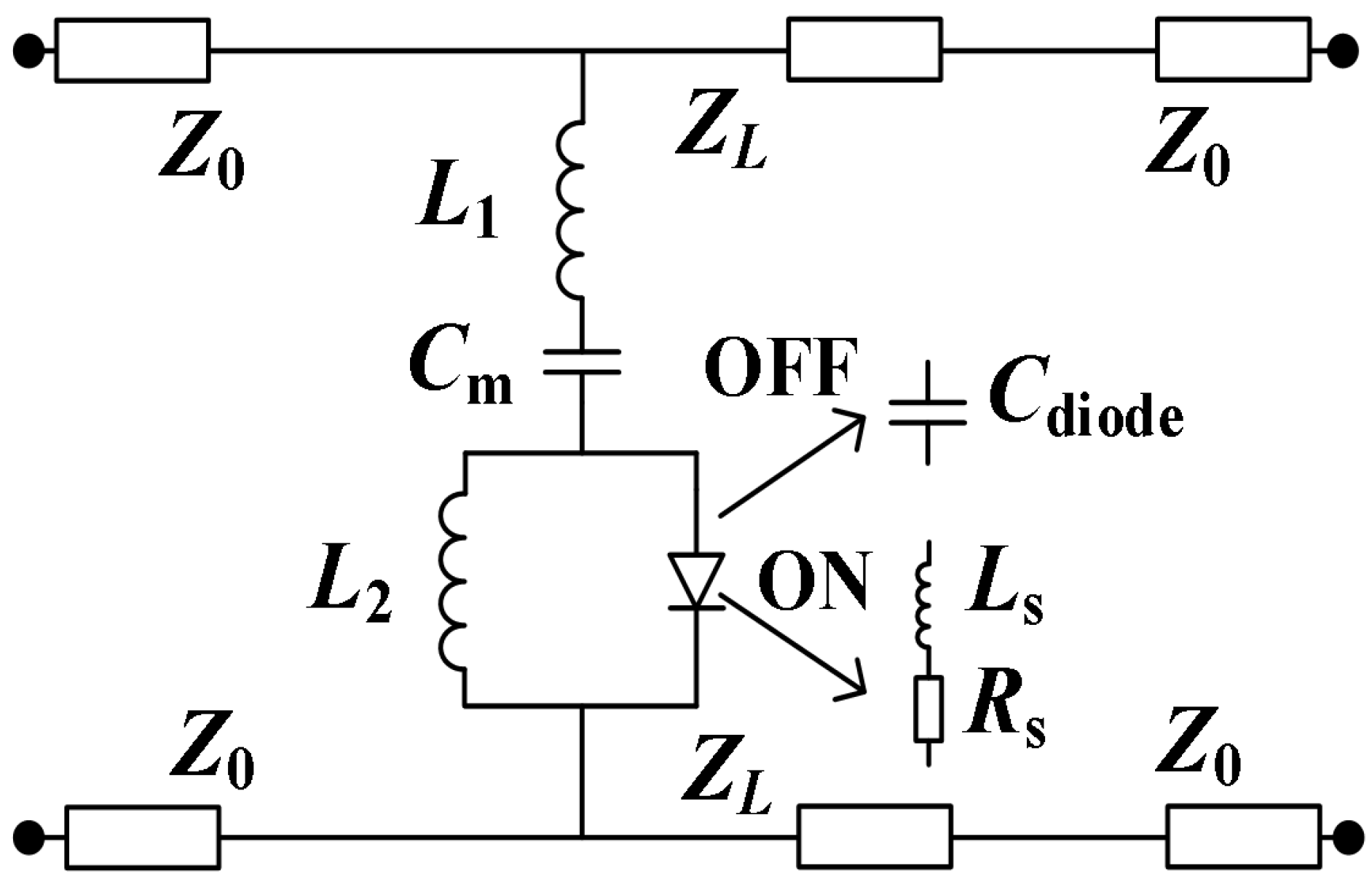
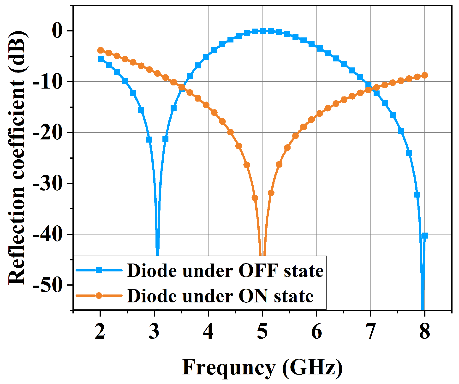
2.1. Theoretical Analysis

The transmission coefficient of conventional ESSs in the face of different incident waves is determined by its equivalent impedance. The transmission coefficient S21 of the ESS can be expressed as
S 21 = 20 lg 1 1 + Z 0 / 2 Z e s s ,
where Z e s s represents the equivalent impedance of the ESS, and Z 0 represents the wave impedance of the free space air. By using the nonlinear characteristics of the diode, the ESS can adapt to the intensity of the incident wave energy to realize the impedance variable. Under weak EM field conditions, the ESS exhibits high impedance, resulting in minimal IL that allows normal signal transmission. However, when EM energy exceeds the safety threshold, the ESS impedance drops sharply, enabling high SE to reflect incident high-power microwave radiation.
According to Floquet theory, the analysis of the whole ESS can be equivalent to the analysis of a single periodic unit. A classic dual-resonant circuit topology designed in this paper is shown in Figure 1, where C m is the lumped capacitor and L 1 is the equivalent inductance of the metal patch. The diode can be equivalent to a resistance and an inductance in the ON state and a capacitor in the OFF state. The specific parameters are shown in Table 1.
According to equivalent circuit analysis, when the normal working signal is incident and the diode is in the OFF state, the impedance of the periodic structure can be expressed as
Z e s s = j ω L 1 + 1 j ω C m + ( j ω L 2 j ω C d i o d e ) .
The circuit resonant model consists of an L C series resonance and an L C parallel resonance. When the frequency is at the resonant frequency, Z e s s reaches its minimum value, causing the transmission coefficient to exhibit band-pass characteristics. It has two resonant points, ω 1 and ω 2 , which were calculated as
ω 1 = 1 2 π L 1 C m ;
ω 2 = 1 2 π L 2 C diode .
When a HIRF is incident, leaving the diode in the ON state, the impedance of the periodic structure can be expressed as
Z e s s = j ω L 1 + 1 j ω C m + j ω L 2 ( j ω L s + R s ) .
The original circuit topology is converted to a single-resonant L C series, which has only one resonant point ω 3 . Z e s s reaches its minimum value at the resonant frequency, resulting in the transmission coefficient exhibiting a band-stop characteristic. The ω 3 was calculated as
ω 3 = 1 2 π L eq C m ,
where L eq was denoted as
L eq = L 1 + L 2 R s 2 + ω 2 L s ( L 2 + L s ) R s 2 + ω 2 ( L 2 + L s ) 2 .
By optimizing and adjusting the parameters, the resonant point ω 3 in the ON state is between the resonant point ω 1 and the resonant point ω 2 in the OFF state. Consequently, simultaneous attainment of minimal IL and maximal SE is observed within the identical frequency range.
As demonstrated in Figure 2, the reflection coefficients of the diode under the OFF/ON states were obtained through simulation of the equivalent circuit topology using the commercial software Advanced Design System 2021 (ADS2021). It is shown that dual-resonant characteristics are presented when the diode is in the OFF state, which facilitates the formation of a pass band. When the diode was turned on, the original dual-resonant configuration was converted to single resonant, resulting in an automatic transition from a pass band to a stop band. Selective EM wave transmission is enabled through dynamic frequency band switching by this mechanism.

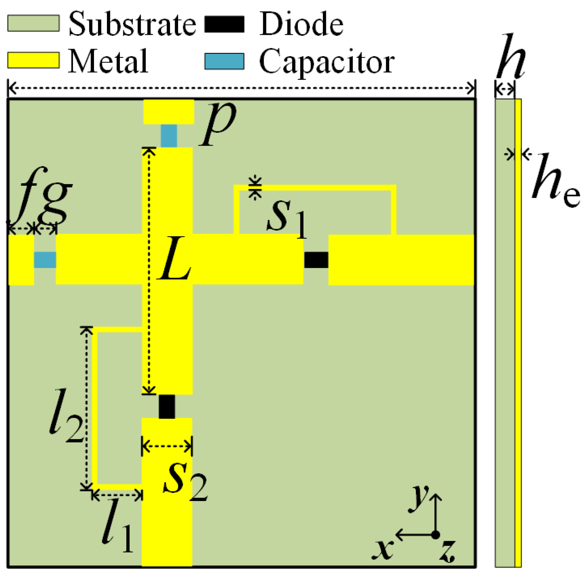
2.2. Structural Design

Based on the topology of the dual-resonant circuit, the ESS unit structure designed in this paper is shown in Figure 3, which includes a layer of periodic metal patch structure and a dielectric substrate. The metal patch is composed of vertically arranged metal strips, a lumped capacitor, and a resonant ring with a diode. Flame-Retardant 4 Epoxy Glass Cloth (FR-4) material with a dielectric constant of 4.3 and a loss tangent of 0.02 was employed for the intermediate dielectric substrate. The dimensional parameters of this structure are shown in Table 2.

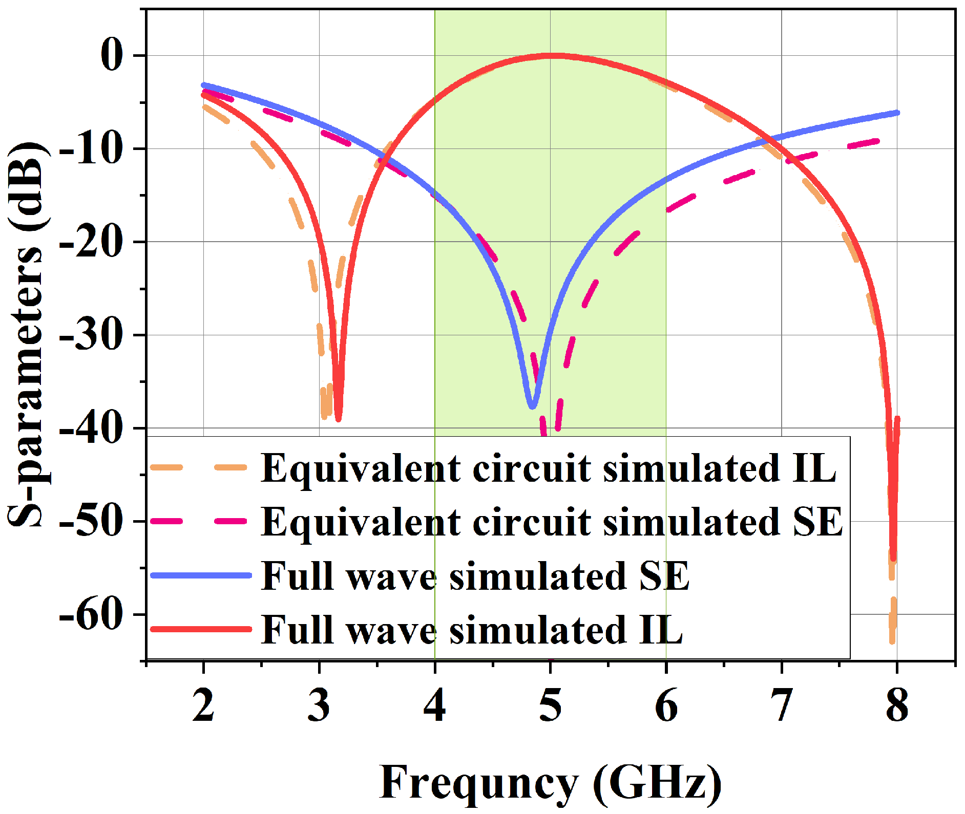
3. Simulation Analysis

In this paper, the commercial software CST-Studio-Suite 2023 (CST) [35] was used to simulate the designed unit structure to test and verify the performance parameters of the proposed ESS. Figure 4 shows the comparison curves by full-wave simulation and equivalent circuit simulation, which represent the reflection coefficient corresponding to the diodes in OFF and ON states. When the normal working signal is incident, the diode presents an OFF state, and the energy selective surface is in a transparent state. Upon HIRF incidents, the diode transitions to an ON state under high-voltage stress, thereby turning the ESS into a shielding state. Results of the transmission curves show that the center frequency of the ESS in the transparent state is 5 GHz, and the frequency band with IL less than 1 dB is 4.53–5.55 GHz. In the shielding state, the center frequency is 4.84 GHz, the SE is greater than 15 dB in the frequency band range of 4.02–5.78 GHz, and the SE is 30 dB in the 4.70–4.98 GHz band. It can be seen that the ESS is capable of protecting against HIRF incidents.
In order to test the dual-polarization characteristics and angular stability of the designed structure, the incident angles of the x o z plane when the TE wave is incident and the y o z plane when the TM wave is incident are respectively changed for simulation tests. TE polarization is the incident wave of the electric field along the y axis, and TM polarization is the incident wave of the magnetic field along the y axis. Figure 5a and Figure 5b respectively show the IL curves corresponding to different incidence angles in the OFF state when the TE and TM polarized waves are incident. Figure 6a and Figure 6b respectively show the SE curves corresponding to different incidence angles in the ON state when the TE and TM polarized waves are incident. The results show that IL and SE at TE and TM polarization incidence are very similar due to the good rotational symmetry of the structure, and the ESS is insensitive to the polarization of the incident wave. With the gradual increase of the incidence angle up to 50°, the IL in the operating frequency range is always less than 3 dB and the SE is always greater than 15 dB, which is in the acceptable range and can meet the basic HIRF protection requirements.
In summary, it can be seen that the ESS has good angular stability and similar characteristics to TE and TM polarization incident waves, which can realize effective protection against dual-polarization incident waves.

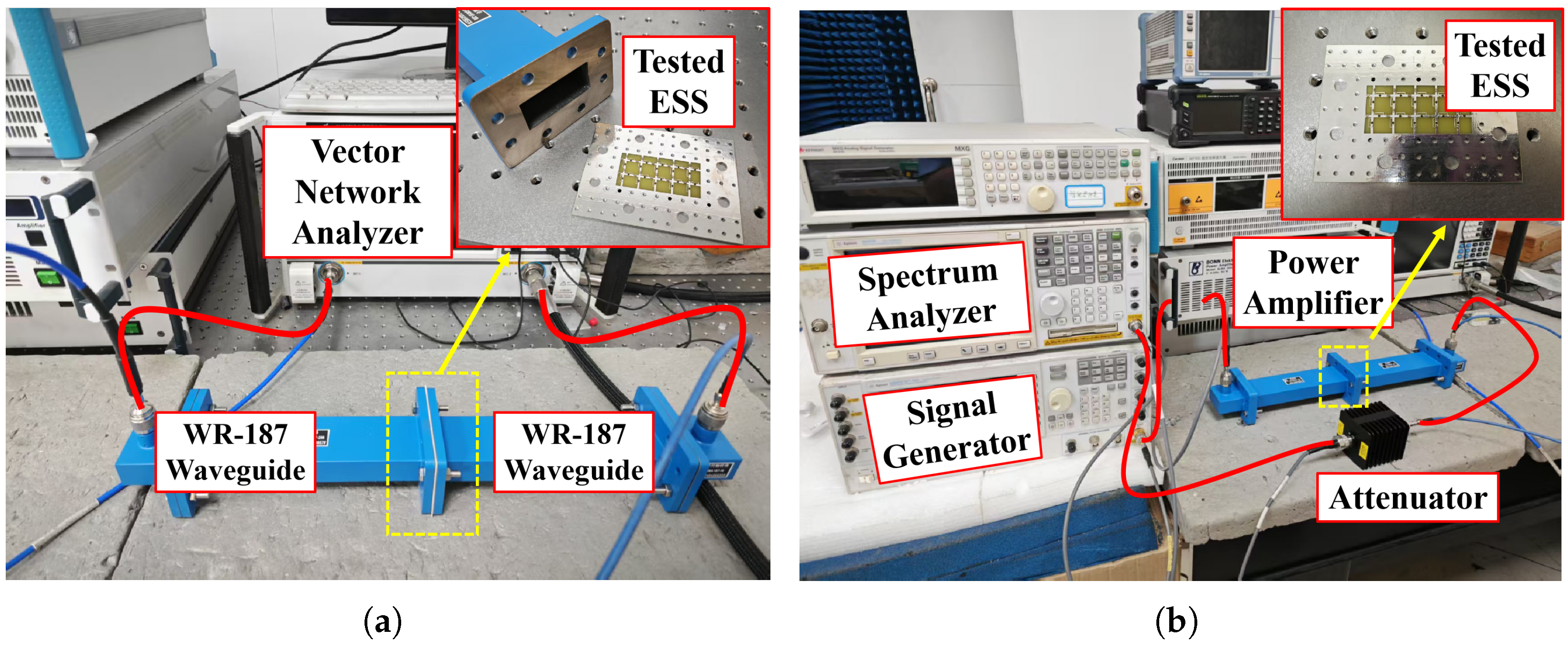
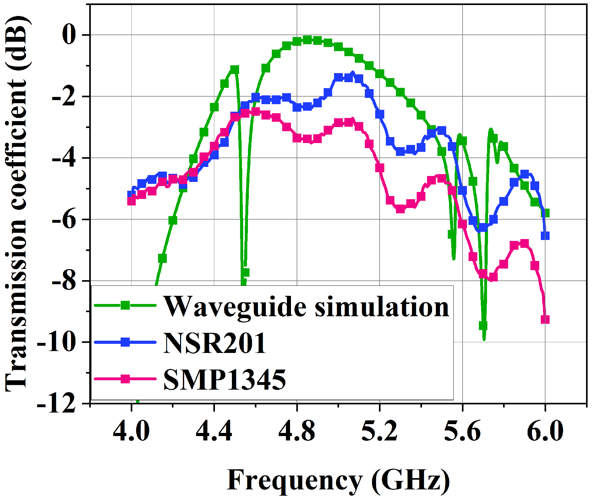
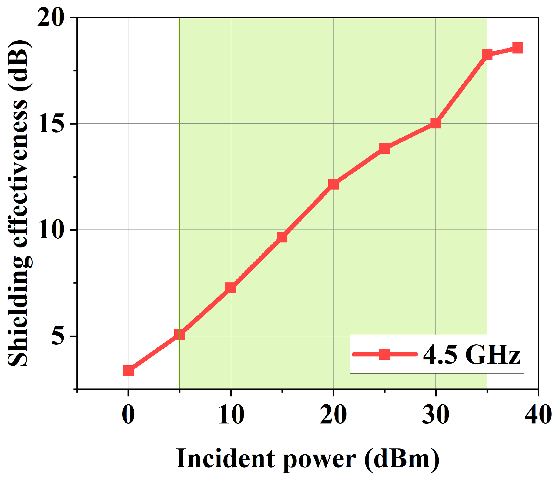
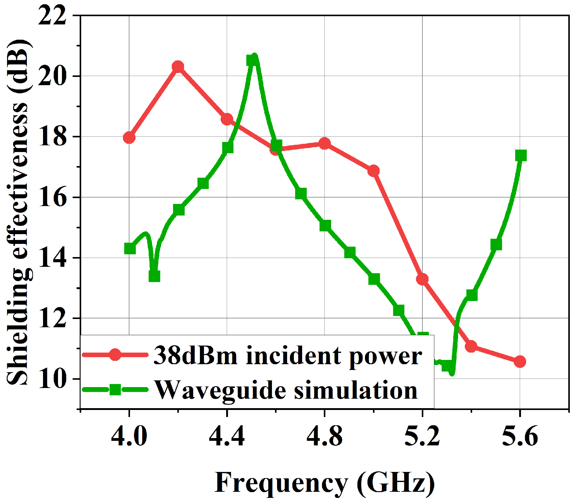
4. Experimental Validation

To validate the IL of the proposed ESS during operational states and its SE under shielding states, waveguide injection experiments were systematically conducted under varying incident signal intensities. The schematic diagram of the experimental procedure is illustrated in Figure 7. A waveguide injection testing methodology was employed, which categorizes the testing pathway for the tested ESS into two distinct paths: a low-level signal path and a HIRF pulse path. These paths were designed to independently assess the EM response characteristics of the tested ESS when subjected to incident waves of disparate magnitudes.
Based on the two EM wave pathways delineated in the experimental flow diagram, separate physical implementations were conducted. The corresponding experimental configurations are depicted in Figure 8a and Figure 8b, respectively. Under varying incident signal power conditions, the transmission coefficient of the ESS under investigation was systematically characterized as a function of frequency and incident wave power.
Given the inherent nonlinear response disparities among diode types, the ESS prototype was fabricated incorporating both Schottky barrier diodes (NSR201) and PIN diodes (SMP1345) for comparative analysis. As depicted in Figure 9, the IL measurements under low-power signal excitation reveal distinct transmission characteristics. Notably, the Schottky diode-integrated ESS demonstrates superior IL performance (−1.22 dB at 5.0 GHz) compared to the PIN diode (−2.35 dB at 4.5 GHz). This phenomenon is attributed to the intrinsic junction capacitance difference, where higher parasitic capacitance is exhibited by PIN diodes, leading to a resonant frequency downshift relative to simulation predictions and enhanced EM wave reflection. The IL is less than 3 dB in the operating bandwidth from 4.47 GHz to 5.23 GHz, yielding a fractional bandwidth of 15 %, which satisfies the design specifications.
Building upon the previous experimental findings, the NSR201 diodes were adapted and the frequency point 4.5 GHz was selected for HIRF single-frequency testing. Figure 10 presents the SE relative to the incident pulse power under ESS-loaded conditions. Notably, diodes conduction initiated at an incident power level of 5 dBm, and the diodes basically turned on when the incident power was achieved at 35 dBm. The ESS achieved a SE exceeding 17 dB under HIRF exposure conditions.
Based on previous experimental results, the frequency-dependent shielding performance of the ESS prototype was evaluated at an incident power level of 38 dBm. As depicted in Figure 11, the measured SE exceeds 17 dB across the 4.0–5.0 GHz bandwidth, with a peak attenuation of 20.31 dB observed at 4.2 GHz. This validates the structure’s effective mitigation of high-power microwave transmission. The measured frequency response exhibits a slight deviation from the simulated predictions, which is primarily ascribed to manufacturing tolerances and unaccounted diode parasitic effects. Future design iterations necessitate holistic optimization strategies incorporating these practical considerations to achieve closer alignment between simulated and measured performances. The comparative analysis of the proposed ESS against existing designs is presented in Table 3. Notably, the dual-resonant circuit topology implemented in this work achieves a superior balance between low IL and high SE compared to conventional single-resonant topology. Performance of the proposed ESS aligns with the stringent requirements for HIRF protection, suggesting the potential for practical implementation in radio frequency front-ends.

5. Conclusions

In this paper, an ESS operating at 4.47–5.23 GHz with low IL and high SE based on the dual-resonant equivalent circuit topology was proposed. The ESS unit consists of two vertically distributed resonant rings loaded with diodes and two lumped capacitors, which realized a signal pass band and a HIRF stop band at 4.0–5.0 GHz. The design principle was revealed by an equivalent circuit model. The fabricated prototype exhibits consistent performance across both TE and TM polarizations due to the good rotational symmetry characteristics of the ESS units. The ESS has excellent angular stability and dual-polarization protection to protect TE and TM polarized HIRFs at an incident angle of up to 50°. Finally, experimental validation of the ESS was conducted under varying incident EM wave power levels using two distinct experimental setups, with the results demonstrating consistency with simulated outcomes.

Author Contributions

Conceptualization, H.Z. and S.Z.; Methodology, H.Z. and J.Z.; Software, H.Z.; Validation, H.Z.; Formal analysis, H.Z. and C.L.; Investigation, H.Z., H.J. and T.Z.; Resources, H.Z.; Data curation, H.Z.; Writing—original draft, H.Z.; Writing—review & editing, H.Z.; Visualization, H.Z.; Supervision, P.L. All authors have read and agreed to the published version of the manuscript.

Funding

This research was funded by National Natural Science Foundation of China: 62293491, National Natural Science Foundation of China: 62293494 and Science Foundation of National University of Defense Technology under Grant ZK2023-17.

Data Availability Statement

Data are contained within the article.

Conflicts of Interest

The authors declare no conflict of interest.

References

  1. Eleftheriades, G.V. Electronics: Protecting the weak from the strong. Nature 2014, 505, 490–491. [Google Scholar] [CrossRef] [PubMed]
  2. Brown, N. Design Concepts for High-Power PIN Diode Limiting. IEEE Trans. Microw. Theory Tech. 1967, 15, 732–742. [Google Scholar] [CrossRef]
  3. Schröder, A.; Rasek, G.A.; Brüns, H.D.; Řezníček, Z.; Kučera, J.; Loos, S.E.; Schuster, C. Analysis of High Intensity Radiated Field Coupling into Aircraft Using the Method of Moments. IEEE Trans. Electromagn. Compat. 2014, 56, 113–122. [Google Scholar] [CrossRef]
  4. Lv, J.; Luo, C.; Zhao, J.; Han, H.; Lu, H.; Zheng, B. Development of Energy-Selective Surface for Electromagnetic Protection. Micromachines 2025, 16, 555. [Google Scholar] [CrossRef]
  5. Zhang, J.; Lin, M.; Wu, Z.; Ding, L.; Bian, L.; Liu, P. Energy Selective Surface with Power-Dependent Transmission Coefficient for High-Power Microwave Protection in Waveguide. IEEE Trans. Antennas Propag. 2019, 67, 2494–2502. [Google Scholar] [CrossRef]
  6. Li, X.; Wang, B.; Ding, Q.; Qiu, S.; Li, H.; Shang, Y. High-Power Mechanical Waveguide Phase Shifter: Electromagnetic Resonance Analysis and Protection Design. IEEE Trans. Microw. Theory Tech. 2025, 73, 760–769. [Google Scholar] [CrossRef]
  7. Ning, Z.; Li, M.; Chen, L.; Gu, J.; Ding, D. Circuit Modelling and Analysis of Multiband Energy-Selective Surfaces Using Characteristic Modes. IEEE Trans. Antennas Propag. 2025. Early Access. [Google Scholar] [CrossRef]
  8. Wu, Q.; Liu, Y.; Wen, Y.; Zhao, M.; Wang, W.; Zhang, J.; Su, D. Non-nuclear Electromagnetic Pulse Threat of Critical Infrastructures and Protection Strategies. Strateg. Study Chin. Acad. Eng. 2022, 24, 249. [Google Scholar] [CrossRef]
  9. Zhou, T.; Liu, P.; Liu, C.; Jiang, H.; Tian, T. Multilayer Energy Selective Surface with Wide Operational Band and High Shielding Effectiveness Based on Second-Order Filter. IEEE Trans. Electromagn. Compat. 2025, 67, 337–340. [Google Scholar] [CrossRef]
  10. Zha, S.; Qu, Z.; Zhang, J.; Zheng, D.; Liu, P. A Gain-Reconfigurable Reflector Antenna with Surface-Mounted Field-Induced Artificial Magnetic Conductor for Adaptive HIRF Prevention. IEEE Trans. Antennas Propag. 2024, 72, 7252–7260. [Google Scholar] [CrossRef]
  11. Fang, J.; Wu, Q. A Non-Reciprocal, Ultrawideband Energy Selective Antenna Based on Conductivity Modulation Effect. IEEE Trans. Electromagn. Compat. 2024, 66, 1836–1847. [Google Scholar] [CrossRef]
  12. Afzal, W.; Baig, M.Z.; Ebrahimi, A.; Robel, M.R.; Rana, M.T.A.; Rowe, W. Frequency Selective Surfaces: Design, Analysis, and Applications. Telecom 2024, 5, 1102–1128. [Google Scholar] [CrossRef]
  13. Kun, L.; Shining, S.; Xinyuan, Z.; Qianqian, S.; Xiangkun, K.; Shaobin, L. A Novel Polarization Converter Based on the Band-stop Frequency Selective Surface. Chin. Phys. B 2022, 31, 024211. [Google Scholar] [CrossRef]
  14. Chen, Z.; Li, Y.; Li, Z.; Guo, C.; Li, Z.; Bing, P.; Wang, S.; Xu, J.; Zhang, H.; Yao, J. Multi-stopband Filter Based on Frequency Selective Surface. Opt. Commun. 2025, 574, 131064. [Google Scholar] [CrossRef]
  15. Zhou, L.; Shen, Z. Diffusive Energy-Selective Surface with Low Backscattering. IEEE Trans. Antennas Propag. 2022, 70, 430–439. [Google Scholar] [CrossRef]
  16. Xiong, H.; Suo, M.; Li, X.; Xiao, D.; Zhang, H. Design of Energy-Selective Surface with an Ultra-wide Shielding Band for High-Power Microwave Protection. ACS Appl. Electron. Mater. 2024, 6, 696–701. [Google Scholar] [CrossRef]
  17. Zhang, Y.; Zhou, L.; Pan, F.; Mao, J.F. Design and Failure Mechanism Analysis of a High-Power Limiter at DC-6 GHz with GaAs PIN Technology. IEEE Trans. Electromagn. Compat. 2025, 67, 227–236. [Google Scholar] [CrossRef]
  18. Backstrom, M.; Lovstrand, K. Susceptibility of Electronic Systems to High-power Microwaves: Summary of Test Experience. IEEE Trans. Electromagn. Compat. 2004, 46, 396–403. [Google Scholar] [CrossRef]
  19. Tian, T.; Huang, X.; Xu, Y.; Liu, P.; Liu, C.; Hu, N.; Zhang, J.; Wu, Z. A Wideband Energy Selective Surface with Quasi-Elliptic Bandpass Response and High-Power Microwave Shielding. IEEE Trans. Electromagn. Compat. 2024, 66, 224–233. [Google Scholar] [CrossRef]
  20. Guo, Y.; Li, G. Energy-Selective-Surface-Based Dynamic Phase Modulation Surface. IEEE Antennas Wirel. Propag. Lett. 2022, 21, 1363–1367. [Google Scholar] [CrossRef]
  21. Fang, J.; Wu, Q.; Su, D. An Energy Selective Antenna Based on the Folded Dipole Structure and PIN Diodes. IEEE Trans. Electromagn. Compat. 2023, 65, 2006–2014. [Google Scholar] [CrossRef]
  22. Yang, C.; Liu, P.G.; Huang, X.J. A Novel Method of Energy Selective Surface for Adaptive HPM/EMP Protection. IEEE Antennas Wirel. Propag. Lett. 2013, 12, 112–115. [Google Scholar] [CrossRef]
  23. Zhao, C.; Wang, C.F.; Aditya, S. Power-Dependent Frequency-Selective Surface: Concept, Design, and Experiment. IEEE Trans. Antennas Propag. 2019, 67, 3215–3220. [Google Scholar] [CrossRef]
  24. Cao, H.; Xie, Y.Z.; Gao, C. Design of an Energy Selective Surface with Broadband Stealth Characteristics. IEEE Trans. Antennas Propag. 2025. Early Access. [Google Scholar] [CrossRef]
  25. Gong, W.; Zhang, W.; Chen, X.; Han, G.; Han, L.; Su, J.; Yang, R. A Low-Profile Energy Selective Surface with Ultra-Wide Absorption Band. IEEE Trans. Microw. Theory Tech. 2023, 71, 1348–1355. [Google Scholar] [CrossRef]
  26. Hu, N.; Wang, K.; Zhang, J.; Zha, S.; Wu, Z.; Liu, C.; Liu, P. Design of Ultrawideband Energy-Selective Surface for High-Power Microwave Protection. IEEE Antennas Wirel. Propag. Lett. 2019, 18, 669–673. [Google Scholar] [CrossRef]
  27. Qin, D.; Zhang, W.; Han, G.; Han, L.; Ma, R.; Chen, X. Circuit-Based Dual-Resonance Energy Selective Surface. IEEE Trans. Electromagn. Compat. 2023, 65, 2015–2021. [Google Scholar] [CrossRef]
  28. Luo, Z.; Zheng, M.; Zheng, C.; Wang, X.; Zhou, L.; Li, Y.B.; Cheng, Q.; Ma, H.F.; Cui, T.J. Digital Nonlinear Metasurface with Customizable Nonreciprocity. Adv. Funct. Mater. 2019, 29, 1906635. [Google Scholar] [CrossRef]
  29. Luo, Z.; Wang, Q.; Zhang, X.G.; Wu, J.W.; Dai, J.Y.; Zhang, L.; Wu, H.T.; Zhang, H.C.; Ma, H.F.; Cheng, Q.; et al. Intensity-dependent metasurface with digitally reconfigurable distribution of nonlinearity. Adv. Opt. Mater. 2019, 7, 1900792. [Google Scholar] [CrossRef]
  30. Yang, X.; Wen, E.; Sievenpiper, D.F. Power-Dependent Metasurface with Self-Induced Bandgap. IEEE Antennas Wirel. Propag. Lett. 2022, 21, 1115–1119. [Google Scholar] [CrossRef]
  31. Zhou, L.; Shen, Z. 3-D Absorptive Energy-Selective Structures. IEEE Trans. Antennas Propag. 2021, 69, 5664–5672. [Google Scholar] [CrossRef]
  32. Zhang, J.; Kang, F.; Liu, Z.; Qu, Z.; Xu, M.; Song, Z.; Liu, P. Design of Ultrawideband Energy Selective Surface Based on Triple-Layer Structure and Semiconductor for HIRF Prevention. IEEE Trans. Antennas Propag. 2025. Early Access. [Google Scholar] [CrossRef]
  33. Wang, M.; Tang, M.; Zhang, H.C.; Mao, J. Energy Selective Antenna: Concept, Design, and Experiment. IEEE Trans. Electromagn. Compat. 2023, 65, 539–545. [Google Scholar] [CrossRef]
  34. Li, M.; Xiao, S.; Bai, Y.Y.; Wang, B.Z. An Ultrathin and Broadband Radar Absorber Using Resistive FSS. IEEE Antennas Wirel. Propag. Lett. 2012, 11, 748–751. [Google Scholar] [CrossRef]
  35. Dassault Systèmes. CST Studio Suite 2023. Available online: https://www.3ds.com/products-services/simulia/products/cst-studio-suite/ (accessed on 1 June 2025).
  36. Ghosh, S.; Srivastava, K.V. A Polarization-Independent Broadband Multilayer Switchable Absorber Using Active Frequency Selective Surface. IEEE Antennas Wirel. Propag. Lett. 2017, 16, 3147–3150. [Google Scholar] [CrossRef]
  37. Wang, X.; Deng, L.; Chen, L.; Qu, M.; Liu, X.; Chen, W. An S-Band Dual-Polarization Energy Selective Surface with Low-Cost Design. In Proceedings of the 2023 International Applied Computational Electromagnetics Society Symposium (ACES-China), Hangzhou, China, 15–18 August 2023; pp. 1–3. [Google Scholar] [CrossRef]
Figure 1. ESS equivalent circuit model.
Electronics 14 03029 g001
Figure 2. Reflection coefficients in OFF/ON states of the circuit topology.
Electronics 14 03029 g002
Figure 3. Dual-resonant ESS unit model.
Electronics 14 03029 g003
Figure 4. Comparison transmission coefficient by full-wave simulation and equivalent circuit simulation.
Electronics 14 03029 g004
Figure 5. Angular stability of IL under incident EM waves with TE- (a) and TM- (b) polarizations.
Electronics 14 03029 g005
Figure 6. Angular stability of SE under incident EM waves with TE- (a) and TM- (b) polarizations.
Electronics 14 03029 g006
Figure 7. Schematic of the measurement setup of waveguide injection test method: (a) low-level signal injection, (b) HIRF incident.
Electronics 14 03029 g007
Figure 8. Physical realization diagram of experimental environment: (a) low-level signal injection, (b) HIRF incident.
Electronics 14 03029 g008
Figure 9. Test diagram of IL under different loading diodes.
Electronics 14 03029 g009
Figure 10. Measured SE of proposed ESS with increasing incident EM wave power.
Electronics 14 03029 g010
Figure 11. Frequency characteristic curve of ESS SE under different incident wave power.
Electronics 14 03029 g011
Table 1. Equivalent circuit parameters.
L 1 /nH L 2 /nH L s /nH C m /pF C diode /pF R s / Ω
5.73.70.450.30.21.5
Table 2. Structural dimension parameters of the proposed ESS.
p/(mm)f/(mm)g/(mm)L/(mm) l 1 /(mm)
9.50.50.55.02.0
l 2 /(mm) s 1 /(mm) s 2 /(mm) h /(mm) h e /(mm)
3.30.11.00.50.035
Table 3. Comparison ESS performances between this paper and others.
Ref.Circuit f 0 IL (dB)/SEDiodes/
NO.Topology(GHz)Freq. Range (GHz)(dB)Geometry (mm2) *
 [16]Single-resonant4.003/(3.65–4.38)154/0.018 λ 2
 [36]Single-resonant7.83/(7.30–9.20)108/0.082 λ 2
 [37]Single-resonant3.193/(2.37–4.00)178/0.025 λ 2
 [26]Dual-resonant3.003/(2.00–4.42)209/0.029 λ 2
 [23]Dual-resonant3.003/(2.71–3.52)184/0.130 λ 2
This paperDual-resonant5.003/(4.46–5.23)204/0.025 λ 2
* λ is the wavelength of central frequency.
Disclaimer/Publisher’s Note: The statements, opinions and data contained in all publications are solely those of the individual author(s) and contributor(s) and not of MDPI and/or the editor(s). MDPI and/or the editor(s) disclaim responsibility for any injury to people or property resulting from any ideas, methods, instructions or products referred to in the content.

