
Improved Soft-Starting Method for Doubly Fed Induction Machines Based on Standstill Rotor-Side Synchronization


Abstract
1. Introduction
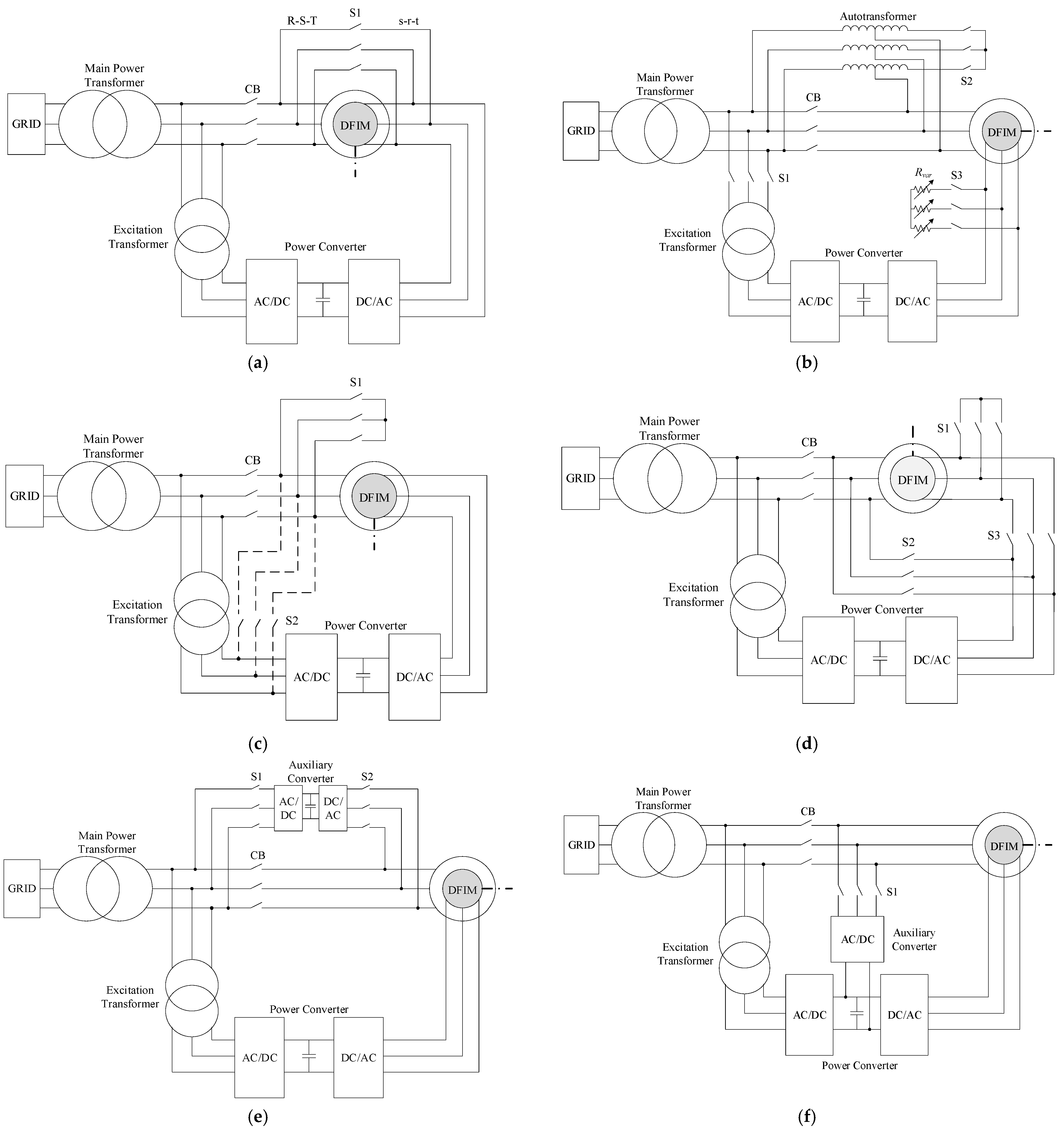
2. State of the Art
2.1. Opposite-Phase Sequence-Based Methods
2.2. Reduced Voltage-Based Methods
2.2.1. Autotransformer and Variable Resistors in the Rotor
2.2.2. Stator Short-Circuit
2.2.3. Rotor Short-Circuit
2.3. Auxiliary Converted-Based Methods
2.4. Previous Standstill Synchronization-Based Method
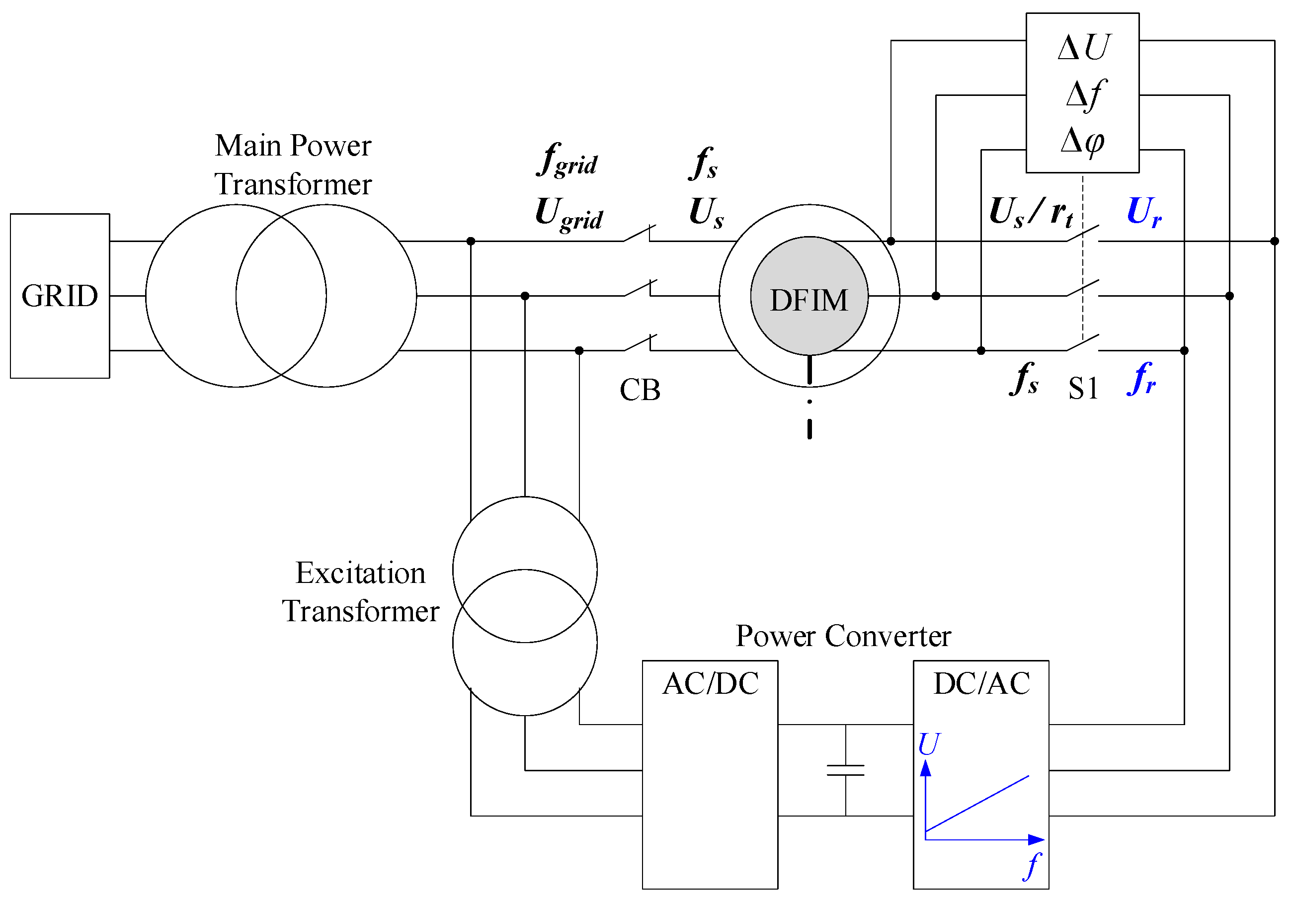
3. Operating Principles of the Proposed Starting Method
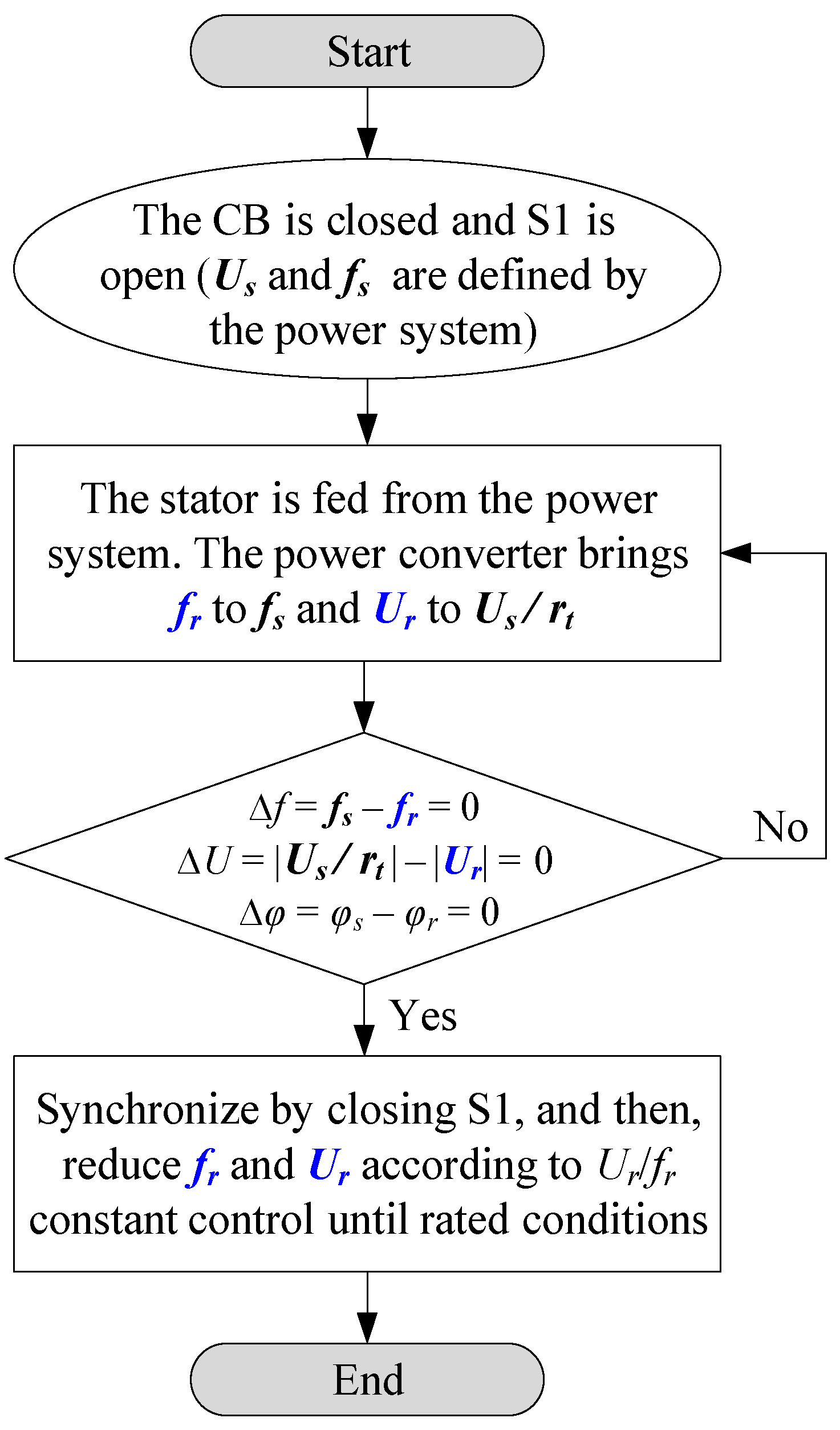
3.1. General Method Outline
3.2. Detailed Method Description
3.3. Theoretical Considerations
3.3.1. General Description of the DFIM
3.3.2. Rotor-Side Synchronization Analysis
3.3.3. Acceleration Analysis
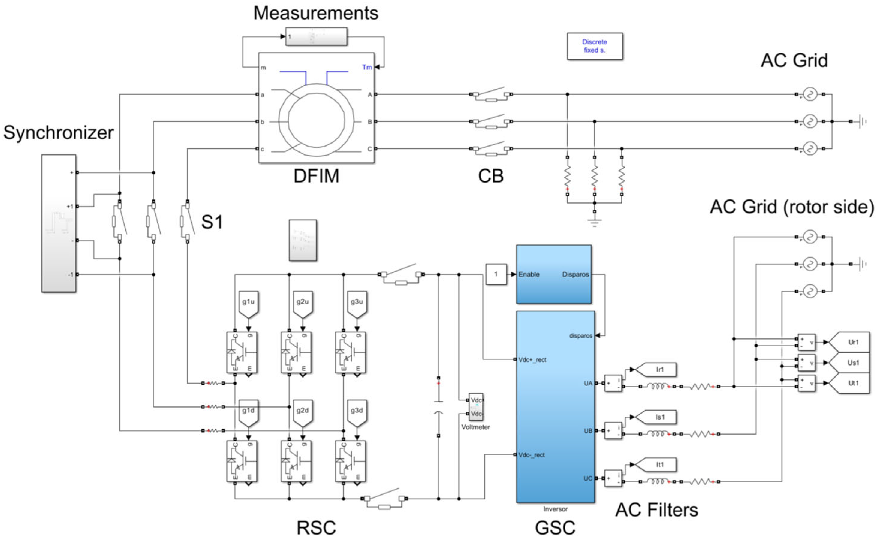
4. Computer Simulations
4.1. Simulation Model
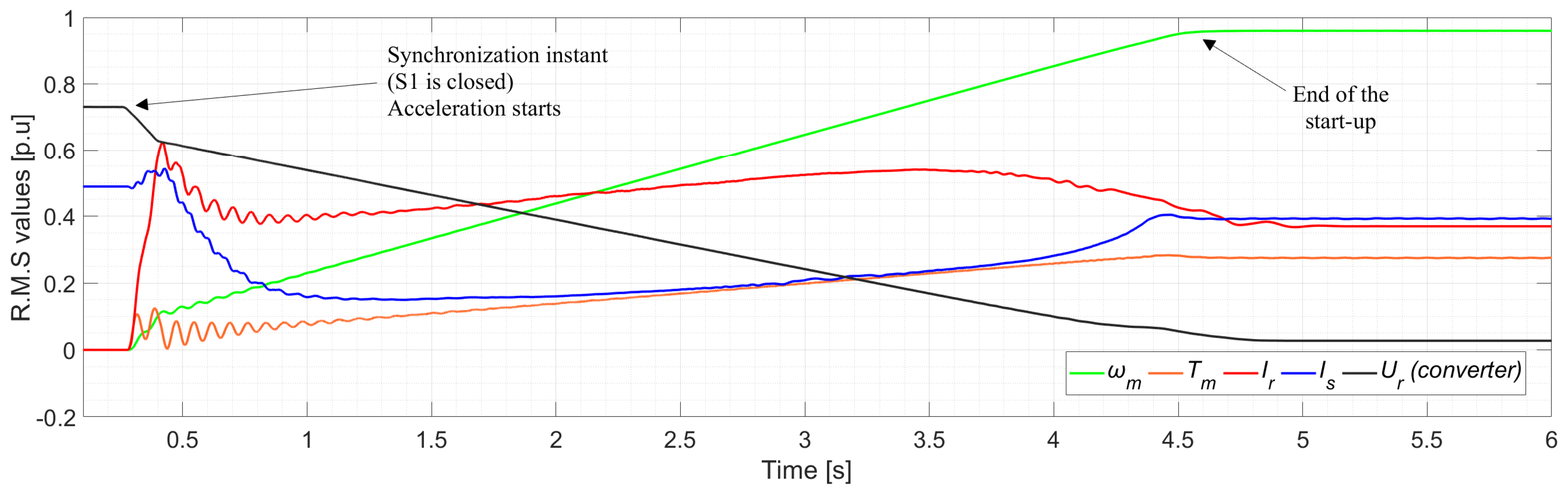
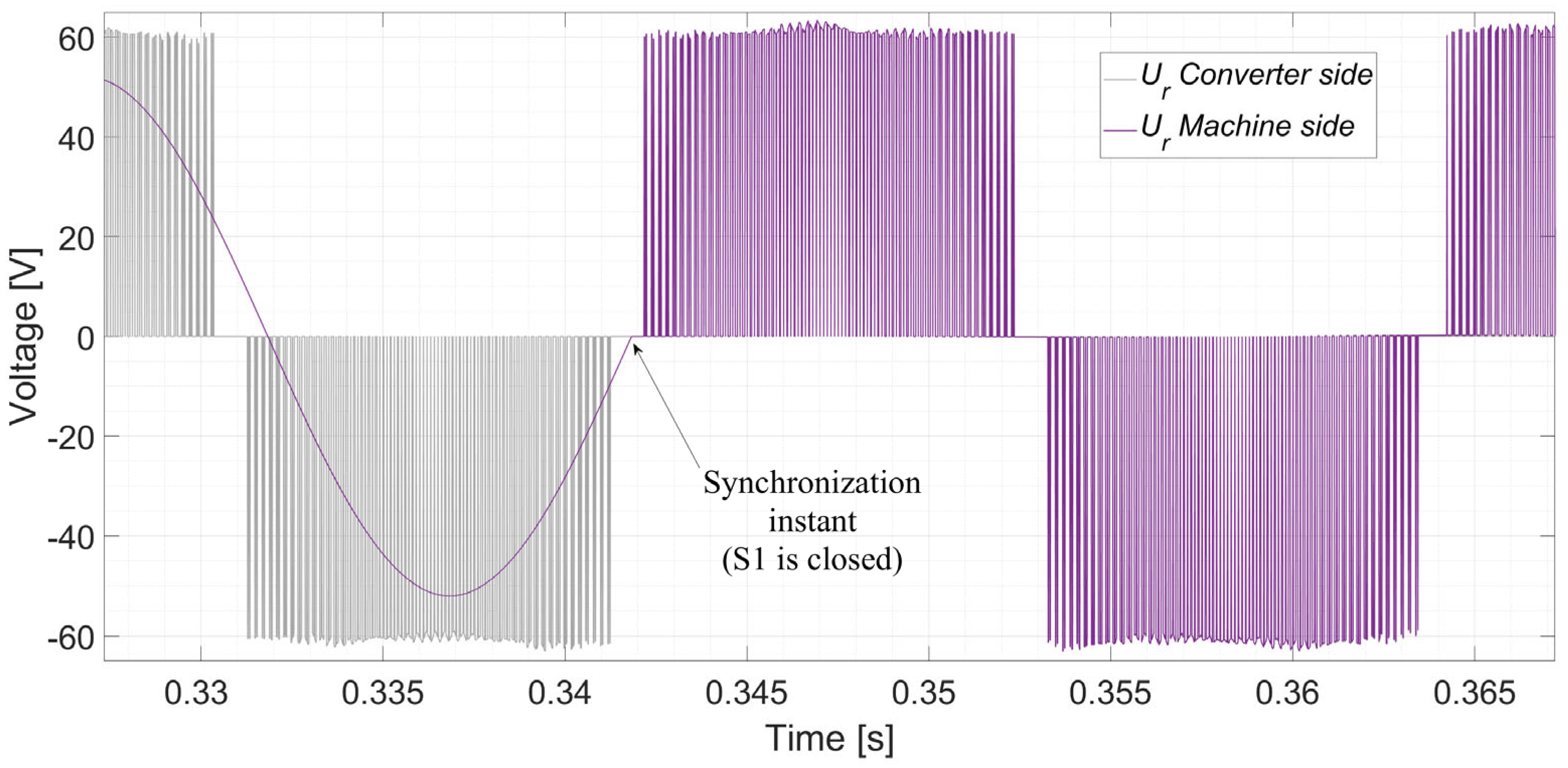
4.2. Simulation Results
5. Experimental Tests
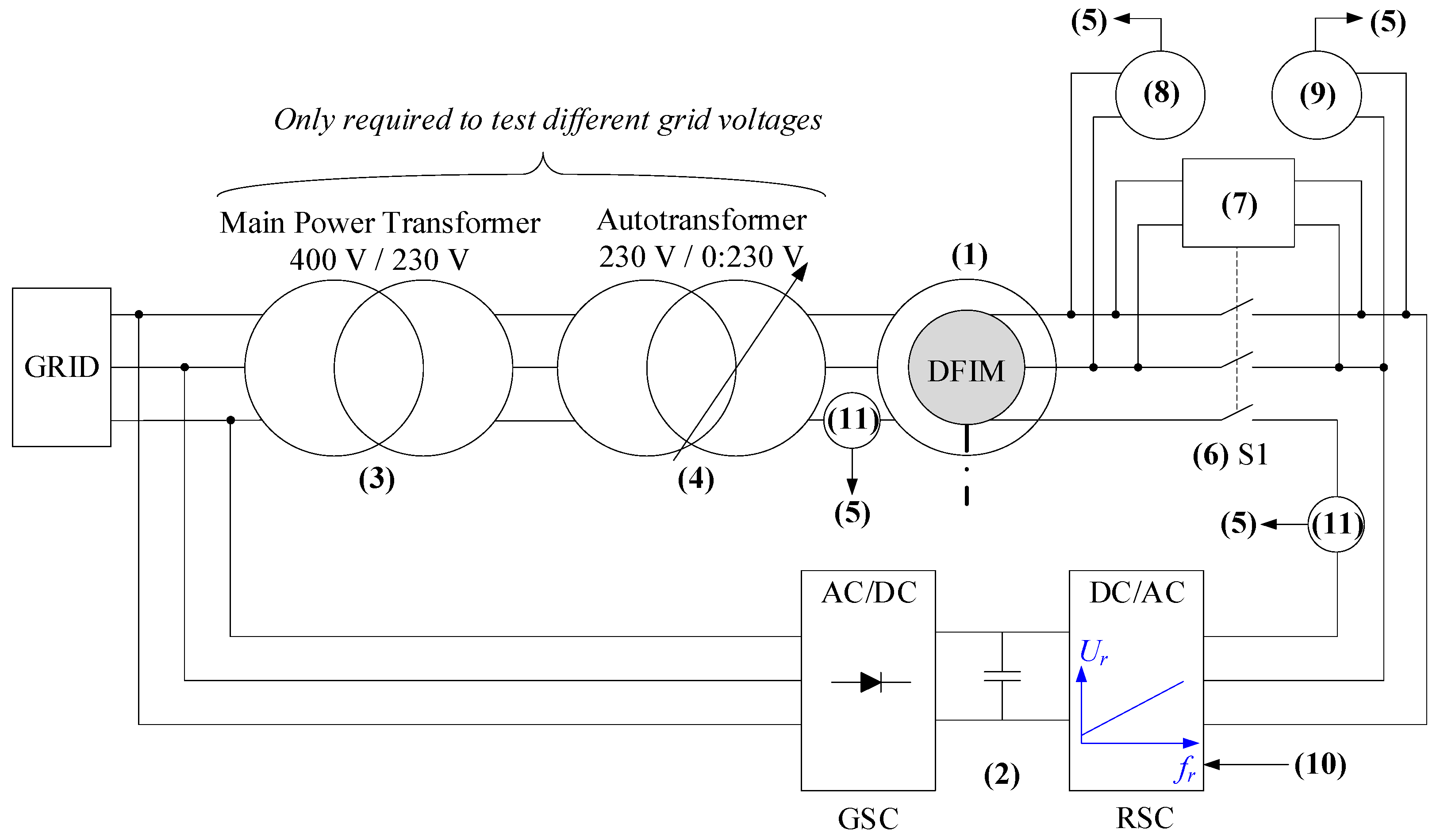
5.1. Experimental Setup
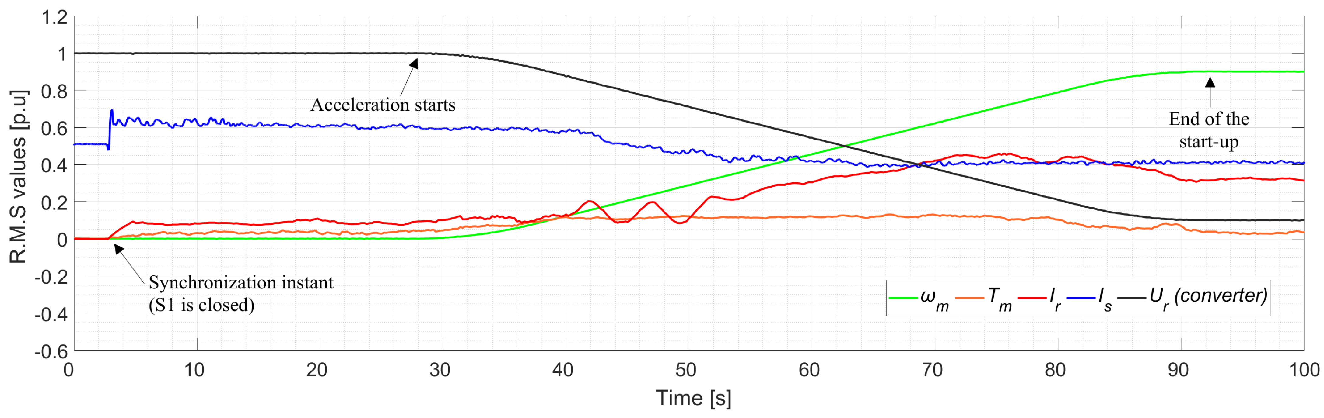
5.2. Experimental Results
6. Discussion
6.1. Findings
- opposite phase sequence-based techniques reach up to 6 p.u. [12];
- reduced voltage-based techniques using autotransformers and variable resistors can reduce the inrush current down to 0.8 p.u. [13];
- and auxiliary converter-based techniques achieve a lower range of the stator-short circuit-based benchmark [31].
6.2. Analysis of Advantages and Limitations
6.3. Influence of the Control Strategy
6.4. Influence of the Modulation Technique
6.5. Influence of Machine Parameters
6.6. Applicability to Higher Power Systems
7. Conclusions
- Reduced complexity and cost: The need for additional components, such as auxiliary converters, autotransformers, or short-circuiting switches, is eliminated, making the system more straightforward and cost-effective.
- Enhanced grid stability: By minimizing inrush currents and avoiding voltage sags, the method supports the stability of power systems, particularly those with weaker configurations. The proposed technique achieves one of the lowest starting current levels among existing methods, comparable to or better than state-of-the-art solutions.
- Smooth startup: The results confirm that the proposed method ensures a seamless acceleration process with reduced transient currents and torque oscillations.
Author Contributions
Funding
Data Availability Statement
Conflicts of Interest
Nomenclature
| Δφ | Phase difference |
| Δf | Frequency difference |
| ΔU | Voltage magnitude difference |
| C | DC bus capacitance |
| fgrid | Grid frequency |
| fr | Converter-fed rotor frequency |
| fs | Stator frequency |
| H | Inertia |
| Ir | Converter-fed rotor current |
| Is | Stator current |
| J | Moment of inertia |
| Lm | Mutual inductance |
| Lr | Rotor inductance |
| Lr′ | Rotor inductance referred to stator |
| Ls | Stator inductance |
| n | Mechanical rotor speed |
| p | Number of pole pairs |
| P | Real power |
| Rr | Rotor resistance |
| Rr′ | Rotor resistance referred to stator |
| Rs | Stator resistance |
| rt | Stator/rotor voltage ratio |
| Rvar | Variable resistance |
| s | Slip |
| Tm | Mechanical torque |
| Tr | Mechanical counter-torque |
| t | Time |
| UDC | DC bus voltage |
| Ugrid | Grid voltage |
| Ur | Converter-fed rotor voltage |
| Us | Stator voltage |
| Xm | Magnetizing reactance |
| Xr | Rotor leakage reactance |
| Xs | Stator leakage reactance |
| φr | Rotor phase angle |
| φs | Stator phase angle |
| Ψr | Rotor flux |
| Ψs | Stator flux |
| ω0 | Angular speed |
| ωm | Mechanical rotor angular speed |
Abbreviations
| AC | Alternating current |
| AT | Autotransformer |
| CB | Circuit breaker |
| DC | Direct current |
| DFIM | Doubly fed induction machine |
| DTC | Direct torque control |
| EMF | Electromotive force |
| FOC | Field-oriented control |
| GSC | Grid-side converter |
| IGBT | Insulated-gate bipolar transistor |
| IK | Impact protection |
| IP | Ingress protection |
| PF | Power factor |
| PLL | Phase-locked loop |
| PWM | Pulse-width modulation |
| RMS | Root mean square |
| RSC | Rotor-side converter |
| SVM | Space vector modulation |
| V/Hz | Volts/hertz |
| VSC | Voltage source converter |
References
- Valavi, M.; Nysveen, A. Variable-Speed Operation of Hydropower Plants: A Look at the Past, Present, and Future. IEEE Ind. Appl. Mag. 2018, 24, 18–27. [Google Scholar] [CrossRef]
- Donalek, P.J. Pumped Storage Hydro: Then and Now. IEEE Power Energy Mag. 2020, 18, 49–57. [Google Scholar] [CrossRef]
- Mahfoud, R.J.; Alkayem, N.F.; Zhang, Y.; Zheng, Y.; Sun, Y.; Alhelou, H.H. Optimal Operation of Pumped Hydro Storage-Based Energy Systems: A Compendium of Current Challenges and Future Perspectives. Renew. Sustain. Energy Rev. 2023, 178, 113267. [Google Scholar] [CrossRef]
- Zhou, Y.; Zhu, Y.; Luo, Q.; Wei, Y.; Mei, Y.; Chang, F.-J. Optimizing Pumped-Storage Power Station Operation for Boosting Power Grid Absorbability to Renewable Energy. Energy Convers. Manag. 2024, 299, 117827. [Google Scholar] [CrossRef]
- Xu, M.; Wu, D.; Wang, D.; Huang, B.; Desomber, K.; Fu, T.; Weimar, M. Optimizing Pumped Storage Hydropower for Multiple Grid Services. J. Energy Storage 2022, 51, 104440. [Google Scholar]
- Shi, L.; Lao, W.; Wu, F.; Zheng, T.; Lee, K.Y. Frequency Regulation Control and Parameter Optimization of Doubly-Fed Induction Machine Pumped Storage Hydro Unit. IEEE Access 2022, 10, 102586–102598. [Google Scholar] [CrossRef]
- Reddy, B.K.; Ayyagari, K.S.; Kumar, Y.P.; Giri, N.C.; Rajgopal, P.V.; Fotis, G.; Mladenov, V. Experimental Benchmarking of Existing Offline Parameter Estimation Methods for Induction Motor Vector Control. Technologies 2024, 12, 123. [Google Scholar] [CrossRef]
- Alizadeh Bidgoli, M.; Yang, W.; Ahmadian, A. DFIM versus Synchronous Machine for Variable Speed Pumped Storage Hydropower Plants: A Comparative Evaluation of Technical Performance. Renew. Energy 2020, 159, 72–86. [Google Scholar] [CrossRef]
- Yaramasu, V.; Wu, B.; Sen, P.C.; Kouro, S.; Narimani, M. High-Power Wind Energy Conversion Systems: State-of-the-Art and Emerging Technologies. Proc. IEEE 2015, 103, 740–788. [Google Scholar] [CrossRef]
- IEEE Std 1010-2022 (Revision of IEEE Std 1010-2006); IEEE Guide for Control of Hydroelectric Power Plants. IEEE: New York, NY, USA, 2023; pp. 1–95.
- Tiwari, R.; Nilsen, R.; Mo, O. Control Strategies for Variable Speed Operation of Pumped Storage Plants with Full-Size Converter Fed Synchronous Machines. In Proceedings of the 2021 IEEE Energy Conversion Congress and Exposition (ECCE), Vancouver, BC, Canada, 10–14 October 2021; pp. 61–68. [Google Scholar]
- Hamouda, R.M.; Alolah, A.I.; Badr, M.A.; Abdel-Halim, M.A. A Comparative Study on the Starting Methods of Three Phase Wound-Rotor Induction Motors. I. IEEE Trans. Energy Convers. 1999, 14, 918–922. [Google Scholar] [CrossRef]
- Zhang, Y.; Ooi, B.T. Adapting DFIGs for Doubly-Fed Induction Motors Operation. In Proceedings of the 2012 IEEE Power and Energy Society General Meeting, San Diego, CA, USA, 22–26 July 2012; pp. 1–8. [Google Scholar]
- Yuan, X.; Chai, J.; Li, Y. A Converter-Based Starting Method and Speed Control of Doubly Fed Induction Machine With Centrifugal Loads. IEEE Trans. Ind. Appl. 2011, 47, 1409–1418. [Google Scholar] [CrossRef]
- Joseph, A.; Selvaraj, R.; Chelliah, T.R.; Sarma, S.V.A. Starting and Braking of a Large Variable Speed Hydrogenerating Unit Subjected to Converter and Sensor Faults. IEEE Trans. Ind. Appl. 2018, 54, 3372–3382. [Google Scholar] [CrossRef]
- Joseph, A.; Desingu, K.; Semwal, R.R.; Chelliah, T.R.; Khare, D. Dynamic Performance of Pumping Mode of 250 MW Variable Speed Hydro-Generating Unit Subjected to Power and Control Circuit Faults. IEEE Trans. Energy Convers. 2018, 33, 430–441. [Google Scholar] [CrossRef]
- Anto, J.; Chelliah, T.R. Starting Performance of Doubly Fed Induction Machine Drive Serving Pumped Storage Plants Subjected to Faults in Power and Control Circuits. In Proceedings of the 2016 IEEE 1st International Conference on Power Electronics, Intelligent Control and Energy Systems (ICPEICES), Delhi, India, 4–6 July 2016; pp. 1–7. [Google Scholar]
- Saiju, R.; Koutnik, J.; Krueger, K. Dynamic Analysis of Start-Up Strategies of AC Excited Double Fed Induction Machine for Pumped Storage Power Plant. In Proceedings of the 2009 13th European Conference on Power Electronics and Applications, Barcelona, Spain, 8–10 September 2009; pp. 1–8. [Google Scholar]
- Pannatier, Y.; Kawkabani, B.; Nicolet, C.; Schwery, A.; Simond, J.-J. Optimization of the Start-Up Time of a Variable Speed Pump-Turbine Unit in Pumping Mode. In Proceedings of the 2012 XXth International Conference on Electrical Machines, Marseille, France, 2–5 September 2012; pp. 2126–2132. [Google Scholar]
- Pannatier, Y.; Kawkabani, B.; Nicolet, C.; Schwery, A.; Simond, J.-J. Start-Up and Synchronization of a Variable Speed Pump-Turbine Unit in Pumping Mode. In Proceedings of the XIX International Conference on Electrical Machines—ICEM 2010, Rome, Italy, 6–8 September 2010; pp. 1–6. [Google Scholar]
- Li, D.; Gong, G.; Lv, J.; Jiang, X.; He, R. An Overall Control of Doubly Fed Variable Speed Pumped Storage Unit in Pumping Mode. In Proceedings of the 2020 IEEE 4th Conference on Energy Internet and Energy System Integration, Wuhan, China, 30 October–1 November 2020; pp. 3709–3714. [Google Scholar]
- Gong, G.; Lv, J.; Jiang, X.; Sun, X. Grid-Connection Control of Doubly Fed Variable Speed Pumped Storage Unit. In Proceedings of the 2021 5th International Conference on Green Energy and Applications (ICGEA), Singapore, 6–8 March 2021; pp. 52–57. [Google Scholar]
- Zhu, K.; Ruan, L. Self-Starting Control Strategy of Variable Speed Pumped Storage Unit Based on Adaptive Full Order State Observer. Meas. Control 2023, 56, 630–637. [Google Scholar] [CrossRef]
- Yang, J.; Zhang, F.; Hou, K.; Zeng, X. Study on Self-Starting Technology of Pumped Storage Unit Considering Iron Loss of Doubled Fed Motor. In Proceedings of the 2024 IEEE 7th International Electrical and Energy Conference (CIEEC), Harbin, China, 14–16 June 2024; pp. 2641–2646. [Google Scholar]
- Ji, L.; Shao, Y.; Sun, J.; Shi, L. Research on Self-Starting Strategy of Variable Speed Pumped Storage Units Based on Model Predictive Control. J. Eng. 2017, 2017, 984–989. [Google Scholar] [CrossRef]
- Maendly, T.; Hodder, A.; Kawkabani, B. Start-Up of a Varspeed Group in Pump Mode: Practical Implementations and Tests. In Proceedings of the 2016 XXII International Conference on Electrical Machines (ICEM), Lausanne, Switzerland, 4–7 September 2016; pp. 1201–1207. [Google Scholar]
- Singh, R.R.; Baranidharan, M.; Subramaniam, U.; Bhaskar, M.S.; Rangarajan, S.S.; Abdelsalam, H.A.; Collins, E.R.; Senjyu, T. An Energy-Efficient Start-Up Strategy for Large Variable Speed Hydro Pump Turbine Equipped with Doubly Fed Asynchronous Machine. Energies 2022, 15, 3138. [Google Scholar] [CrossRef]
- Singh, R.R.; Chelliah, T.R. Energy Saving Start-Up Strategy of Pumped Storage Power Plant Equipped with Doubly-Fed Asynchronous Machine. In Proceedings of the 2016 IEEE 1st International Conference on Power Electronics, Intelligent Control and Energy Systems (ICPEICES), Delhi, India, 4–6 July 2016; pp. 1–6. [Google Scholar]
- Pérez-Díaz, J.I.; Cavazzini, G.; Blázquez, F.; Platero, C.; Fraile-Ardanuy, J.; Sánchez, J.A.; Chazarra, M. Technical Report, Mechanical Storage Subprogramme, Joint Programme on Energy Storage. In Technological Developments for Pumped-Hydro Energy Storage; European Energy Research Alliance: Brussels, Belgium, 2014. [Google Scholar]
- Narayanasamy, M.; Sukhi, Y. Rotor Short-Circuited Start-Up Strategy for a Doubly Fed Induction Machine-Fed Large-Rated Variable-Speed Pumped Storage Unit Operating in Pumping Mode. J. Power Electron. 2023, 23, 1733–1744. [Google Scholar] [CrossRef]
- Malathy, N.; Sukhi, Y. Improved Start-Up Strategy for a Doubly Fed Induction Machine Fed Large Rated Variable Speed Pumped Storage Unit in Pumping Mode Operation. Electr. Eng. 2023, 106, 615–629. [Google Scholar] [CrossRef]
- Guerrero, J.M.; Mahtani, K.; Aranzabal, I.; Gómez-Cornejo, J.; Sánchez, J.A.; Platero, C.A. A Soft Start Method for Doubly Fed Induction Machines Based on Synchronization with the Power System at Standstill Conditions. Machines 2024, 12, 847. [Google Scholar] [CrossRef]
- Kovács, P.K. Transient Phenomena in Electrical Machines. In Studies in Electrical and Electronic Engineering; Elsevier: Amsterdam, The Netherlands, 1984. [Google Scholar]


| Type | Method | References | Advantages | Limitations |
|---|---|---|---|---|
| Opposite-phase sequence-based | [12] |
|
| |
| Reduced voltage-based | With autotransformer | [13] |
|
|
| Stator short-circuited | [14,15,16,17,18,19,20,21,22,23,24,25,26,27,28,29] |
|
| |
| Rotor short-circuited | [14,18,30] |
|
| |
| Auxiliary converter-based | [29,31] |
|
| |
| Standstill synchronization-based | Stator-side synchronization | [32] |
|
|
| Rotor-side synchronization (proposed method) |
|
| ||
| Parameter | Magnitude | Units |
|---|---|---|
| Real power (P) | 0.52 | kW |
| Stator voltage (Us) | 400 | V |
| Frequency (fs) | 50 | Hz |
| Stator/rotor voltage ratio (rt) | 10/1 | V/V |
| Stator resistance (Rs) | 30.0 | Ω |
| Stator inductance (Ls) | 0.120 | H |
| Equivalent rotor resistance (Rr′) | 30.0 | Ω |
| Equivalent rotor inductance (Lr′) | 0.120 | H |
| Mutual inductance (Lm) | 2.432 | H |
| Moment of inertia (J) | 0.0015 | kg·m2 |
| Number of pole pairs (p) | 2 | |
| Speed (n) | 1400 | rpm |
| Parameter | Magnitude | Units |
|---|---|---|
| Real power (P) | 7.5 | kW |
| Stator voltage (Us) | 230/400 | V |
| Stator current (Is) | 32/18 | A |
| Rotor voltage (Ur) | 190 | V |
| Rotor current (Ir) | 24 | A |
| Power factor (PF) | 0.70 | |
| Frequency (fs) | 50 | Hz |
| Stator/rotor voltage ratio (rt) | 2.10/1 | V/V |
| Stator resistance (Rs) | 0.25 | Ω |
| Stator inductance (Ls) | 0.875 | mH |
| Equivalent rotor resistance (Rr’) | 1.55 | Ω |
| Equivalent rotor inductance (Lr’) | 5.425 | mH |
| Mutual inductance (Lm) | 0.135 | H |
| Moment of inertia (J) | 0.0439 | kg·m2 |
| Number of pole pairs (p) | 2 | |
| Rated speed (n) | 1447 | rpm |
| Mounting code | B3 | |
| Weight | 136 | kg |
| Diameter/height ratio | 6 | |
| Ingress protection (IP) code | 55 | |
| Impact protection (IK) rating | 08 | |
| Insulation class | F | |
| Duty type | S3 (100%) | |
| Maximum ambient temperature | 40 | °C |
| Bearings (driving end) | 6309 Z C3 | |
| Bearings (non-driving end) | 6309 C3 | Ω |
Disclaimer/Publisher’s Note: The statements, opinions and data contained in all publications are solely those of the individual author(s) and contributor(s) and not of MDPI and/or the editor(s). MDPI and/or the editor(s) disclaim responsibility for any injury to people or property resulting from any ideas, methods, instructions or products referred to in the content. |
© 2024 by the authors. Licensee MDPI, Basel, Switzerland. This article is an open access article distributed under the terms and conditions of the Creative Commons Attribution (CC BY) license (https://creativecommons.org/licenses/by/4.0/).
Share and Cite
Mahtani, K.; Guerrero, J.M.; Sánchez, J.A.; Platero, C.A. Improved Soft-Starting Method for Doubly Fed Induction Machines Based on Standstill Rotor-Side Synchronization. Electronics 2025, 14, 48. https://doi.org/10.3390/electronics14010048
Mahtani K, Guerrero JM, Sánchez JA, Platero CA. Improved Soft-Starting Method for Doubly Fed Induction Machines Based on Standstill Rotor-Side Synchronization. Electronics. 2025; 14(1):48. https://doi.org/10.3390/electronics14010048
Chicago/Turabian StyleMahtani, Kumar, José M. Guerrero, José A. Sánchez, and Carlos A. Platero. 2025. "Improved Soft-Starting Method for Doubly Fed Induction Machines Based on Standstill Rotor-Side Synchronization" Electronics 14, no. 1: 48. https://doi.org/10.3390/electronics14010048
APA StyleMahtani, K., Guerrero, J. M., Sánchez, J. A., & Platero, C. A. (2025). Improved Soft-Starting Method for Doubly Fed Induction Machines Based on Standstill Rotor-Side Synchronization. Electronics, 14(1), 48. https://doi.org/10.3390/electronics14010048