Abstract
This paper reports on the hardware implementation of a digital insulin-glucose regulator for type 2 diabetic patients by using a Field Programmable Gate Array board. For a real time-control of the patient insulin concentration, the insulin-regulator needs to measure only his blood glucose concentration. With respect to other reported solutions using general-purpose programmable hardware’s, the proposed insulin-glucose regulator allows to design a software-free, fully-hardware architecture of the system here described in detail. A prototype has been developed so to validate its functionality in the following two operating modes: (i) in the open loop condition for which only the insulin-glucose regulator is operating; (ii) in the closed loop condition for which the insulin-glucose regulator acting as an artificial pancreas is connected to a population of one hundred virtual patients individuated by employing a comprehensive theoretical model recognized by the U.S. Food and Drug Administration for the pre-clinical validation of glucose control strategies. These virtual patients present the same trend of the variation of the glucose concentration achieving different maximum and minimum values of glucose concentrations when eating a meal. The paper presents and discusses the experimental results by comparing them with those ones obtained by implementing the theoretical model through numerical simulations performed in SIMULINK. Relative errors lower than ±1% have been achieved by performing this comparison so demonstrating a very high accuracy of the proposed insulin-glucose regulator digital system. The implemented hardware solution of the digital controller can process the input data related to the glucose concentration of each virtual patient in about 1.1 μs with an estimated power consumption of about 36 mW. These achievements open the way for further investigations on digital architectures for glucose regulators to be integrated in VLSI as System-on-Chips and/or Lab-on-Chips for portable, wearable, and implantable solutions in real biomedical applications.
1. Introduction
The Diabetes Mellitus (DM) is a chronic disease for which the insulin hormone becomes unable to control the glucose concentration in the blood of patients. Two types of diabetes are recognized: patients affected by Type 1 DM (T1DM) suffer of a total lack of production of pancreatic endogenous insulin; patients affected by Type 2 DM (T2DM) are not able to fully compensate glucose changes in blood by an appropriate insulin production that often can be associated to some resistance to insulin action. If compared, T2DM is the most common type of DM affecting more than 415 million patients worldwide of all cases of diabetes with important implications on the budget of the national health services [1,2,3]. Recently, it has been verified that one of the consequences derived by SARS-CoV-2 infections has been a strong increase in the need of insulin [3,4]. For T1DM patients various Artificial Pancreas (APs) solutions have been proposed and implemented for in blood glucose regulation to guarantee the best health conditions and, consequently, the day-to-day life quality of diabetic patients [5,6,7,8,9]. Differently, glucose regulator solutions for T2DM are very few in the literature. In general, from the technical point of view, APs solutions combine sensors, actuators, and control systems to implement a plasma glucose therapy also considering the specific need of the patient in his daily activities.
A key aspect to be considered in designing a glucose regulator for an AP is the time sampling of the patient glucose concentration and its quantization in the implemented digital devices [10,11,12,13]. In this regard, sampled-data glucose regulators for T2DM patients have been proposed by exploiting both insulin and glucose measurements [14,15]. However, for real time AP operations, direct insulin measurements are not exploitable since they need the use of specific chemical reagents, a drawback that can be only overcome by measuring the blood glucose concentration [16,17]. For this, efforts have been focused on the hardware design and implementation of glucose regulators to achieve control systems for portable and wearable devices operating in low-voltage low-power conditions to ensure reliability, safety, and low cost [18,19,20,21,22]. Design of embedded solutions based on microcontrollers have been investigated even by using smartphones [19,20,21]. Thus, the control system can measure the glucose concentration and suitably drives the pump for the insulin infusion in the patient body providing the hardware security of the medical device [23,24,25]. All these solutions employ commercially available programmable hardware components that do not allow for the integration on-chip of the analog and digital circuitries, the only way to minimize the system size, weight, and total power consumption. In order to avoid this problem, Field Programmable Gate Array (FPGA)-based solutions are largely used for fast prototyping and testing of full-custom integrated solutions and to control the communication of digital systems for biomedical applications [26,27,28,29]. In this sense, in [17] is reported the theoretical model of a digital static output feedback glucose regulator considering the presence of quantization in both the input and output regulator channels. By following the theoretical model discussed in [17], aim of this paper is to present the fully-hardware implementation on an FPGA board of the quantized sampled–data glucose regulator system for T2DM patients. With respect to the previous work [29], this paper includes a complete detailed description of the implemented digital architecture and reports a series of measurements to validate the performances of the insulin-glucose regulator applied on a population of one hundred different Virtual Patients (VPs) by employing a comprehensive theoretical model recognized by the U.S. Food and Drug Administration for the pre-clinical validation of the glucose control strategies. The achieved experimental results demonstrate that the obtained control of the insulin concentration in the patient’s body differs of only 1% with respect to what is expected from theory with the system total power consumption of 36 mW. This proves that the proposed solution allows to obtain very good performances in terms of accuracy in the medical response and power consumption. Moreover, the FPGA-based implementation of the glucose regulator system opens the possibility to design a microelectronic integrated System-on-Chip of the insulin-glucose regulator so allowing its fully-hardware operation (i.e., a software-free architecture).
2. Design of the Glucose Regulator
The developed digital glucose regulator system has been designed by exploiting a model–based approach and its implementation has been tested within a virtual environment recognized by the U.S. Food and Drug Administration (FDA) for pre-clinical validation of this kind of medical devices. The following paragraphs are devoted to describing the theoretical models to control the status and response of the VP with respect to variations of the blood glucose and insulin concentrations and the consequent algorithm implementing the glucose regulation. Moreover, a description of the virtual clinical environment used for testing the glucose regulator system is also reported.
2.1. Glucose-Insulin Model
Under the clinical validation framework, the differential equations describing the nonlinear time-delay of the glucose-insulin system employed to design the proposed glucose regulator are the following [17,30,31]:
where in (mmol/L) is the VP time dependent glucose concentration while in (pmol/L) is the time dependent insulin concentrations to be infused in the VP body; in (min−1(pmol/L)−1) the insulin-dependent glucose uptake rate of insulin concentration; in (min−1(mmol/kgBW)) the net balance between hepatic glucose output and insulin-independent zero-order glucose tissue uptake; and in (L/kgBW) the glucose and insulin distribution volumes, respectively; in (min−1) the constant elimination rate for insulin; in (min−1(pmol/kgBW)) the maximal rate of second-phase insulin release; models the endogenous pancreatic insulin delivery rate through the sigmoidal function introduced in [30,31] to consider the pancreas response to changes of blood glycemia with in (min) a parameter; in (pmol/kgBW) is the exogeneous intravenous insulin delivery rate to the VP body. The initial conditions of the system of differential Equation (1) corresponding to the values of the VP glycemia and insulinemia and before the start of the insulin therapy are typically taken equal to some constant basal levels and . Once chosen a reference value for the desired glycemia , using the differential Equation (1) it is possible to obtain the corresponding value for insulinemia and the insulin delivery rate .
2.2. The Glucose-Insulin Regulator
The core of the glucose-insulin regulator is the AP system that is implemented by exploiting the glucose-insulin mathematical model of the differential Equation (1) with the aim to use a hardware architecture based on an FPGA board by starting from the theoretical model reported in [17]. The insulin concentration to be infused in the VP body for each acquisition of the value of glycemia at time is given by the following equation:
where is a positive scalar control tuning parameter.
2.3. Virtual Clinical Environment
In Figure 1 is shown the complete closed–loop control scheme of the proposed glucose regulator used for its pre-clinical validation. Considering for the moment only the left part of Figure 1, the upper green framed box represents the VP body whose status and response to variations of the glucose and insulin concentrations are emulated by the differential Equation (1); the lower red framed box is the insulin treatment decision controller (i.e., the AP system) that operates by implementing the algorithm of Equation (2). It is important to note that the architecture of Figure 1 is also used to validate different mathematical models of glucose-insulin regulators that include a meal simulation model specifically designed for these systems [31,32]. Moreover, this architecture has been demonstrated capable to describe the medical needs of T2DM patients with a very high accuracy and constitutes the bases of the UVA/Padova Type 1 Diabetes Simulator [33], recognized by the U.S. FDA as a valid alternative to animal tests and extensively used in the AP literature [6,8,34,35,36].
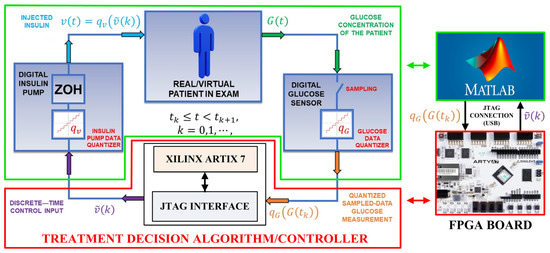
Figure 1.
On the left: the closed–loop control scheme of the insulin-glucose regulator. On the right: The SIMULINK model simulating the VP and the FPGA board implementing the AP system.
3. Hardware Implementation on FPGA Board of the Treatment Decision Controller
Referring to the left side of Figure 1, the proposed insulin-glucose control system is composed of an upper green framed box that emulates the VP and a lower red framed box representing the treatment decision controller the emulates the AP operations. In the closed-loop condition both the VP and AP boxes are connected by using Equations (1) and (2). The insulin-glucose controller operates as follows: (i) the time dependent VP glucose concentration is sampled at each instant by the digital glucose sensor that returns VP quantized glucose concentrations (i.e., emulating the analog-to-digital conversion of the value at the sampling time ). This is the digital input data of the treatment decision controller. The input and that one taken at the instant previously saved in a buffer are used to calculate the interpolated value (i.e., the parameter of Equation (2)) with a constant whose value is chosen as a function of the VP dependent glucose and insulin constants in Equation (1); (ii) by using Equation (2), the treatment decision controller determines the corresponding digital value of the insulin concentration related to the th interpolation; (iii) the value of the insulin concentration is the input of the digital input pump that transforms it in the quantized parameter where is a constant related to the characteristics of the employed infusion pump (i.e., determines, for example, the number of impulses for a digital pump needed to infuse the calculated value of the insulin in the VP body). In general, the insulin infusion can act continuously in between two consecutive sampling instants and . In this sense, the insulin concentration to be infused by the digital pump can be written as .
The above defined closed loop operating condition has been implemented in two different ways: (i) by employing a full software approach using the tools provided by SIMULINK. In this case, the operations of the instruments reported within the red and green framed boxes of Figure 1 have been simulated by a developed SIMULINK model. The values of the input and output quantized glucose concentrations, and the insulin concentrations and are calculated by using Equations (1) and (2). In the following, the results achieved by this approach are identified as the software data; (ii) by employing a mixed software/hardware approach. Referring to the right side of Figure 1, the operations of the instruments related to the VP are still simulated by the same SIMULINK model. As before, the SIMULINK model generates the quantized glucose concentrations that are the input values for the treatment decision controller now implemented by a Xilinx FPGA Artix 7 board. Therefore, the values of the insulin concentrations to be infused in the VP body are calculated by implementing the algorithm of Equation (2) on the FPGA board. In the following, these values of are identified as the hardware data. In both these two approaches, every 10 min over a range of 24 h the value of the VP glucose concentration is acquired, and the corresponding insulin concentrations are calculated. Focusing now on the software/hardware mixed architecture, a MATLAB R2022a script acquires each SIMULINK generated VP quantized glucose concentration converting it in a 32-bit single precision floating point number. Through a JTAG interface, this number is saved in a defined address of a RAM block integrated in the treatment decision controller. Once the optimal value of the insulin concentration is calculated by the hardware architecture, the result is stored in the same RAM block previously used for the glucose concentration.
At this moment, the SIMULINK model receives the calculated insulin concentration that drives the implemented digital insulin pump to infuse the insulin rate in the VP body before acquiring the subsequent value of the glucose concentration through the emulated digital glucose sensor. Referring to Figure 1, the more detailed internal digital architecture, developed on the FPGA board, implementing the treatment decision controller is reported in Figure 2, while the corresponding block scheme is shown in Figure 3.
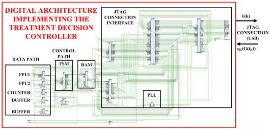
Figure 2.
Digital architecture implementing the insulin treatment decision controller on the FPGA board.
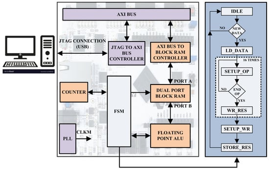
Figure 3.
Digital architecture at block level of the insulin treatment decision controller implemented on the FPGA board.
Referring to Figure 1, the detailed complete digital system implemented in the XILINX ARTIX 7 FPGA-based board is shown in Figure 2: it is composed by a JTAG connection interface able to transmit/receive data to/from the VP and an elaboration unit capable to implement the insulin treatment decision controller. More in details, each single operation is performed by the DATA PATH block composed by an Arithmetic Logic Unit (ALU) implemented by two Floating Point Unit (FPU) modules (i.e., FP1 and FP2), a COUNTER module and two data BUFFER modules. The FPU1 module performs the Multiply-Accumulate (MAC) and subtraction operations and the FPU2 module the division operations. The COUNTER module is used as a timer and the two BUFFER modules store the partial operation results. The CONTROL PATH block is composed by a Finite State Machine (FSM) module, designed by referencing to the Moore model, that manages the algorithm operations. The RAM block stores the initial values of the glucose and insulin concentrations and the results of the executed elaborations as before described. Finally, a Phase-Locked Loop (PLL) block generates the machine clock CLKM and the INTERFACE CONTROLLER block manages the communication between the FPGA board and the VP body.
Referring to the block scheme of treatment decision controller in left part of Figure 3, the I/O data managed by an AXI BUS CONTROLLER module, flow through the AXI BUS module and are read/stored into a true DUAL PORT BLOCK RAM module using the BLOCK RAM CONTROLLER module. At every time a new value of the glucose concentration is stored, the FSM module reads it and controls the sequence of the operations implementing Equation (2). Each operation is executed by the DATA PATH module in Figure 2 as above described. Once the value of the insulin concentration is elaborated, the FSM module writes it in the DUAL PORT BLOCK RAM module. This value is read by a MATLAB script and sent to the SIMULINK model for the insulin infusion in the VP body. The PLL module generates the required synchronism signal CLKM equal to 166 MHz. Referring to the right panel of Figure 3, the FSM module is composed by 36 states (i.e., 32 operation states, 3 setup states and 1 idle state) and executes the following flowchart: (i) waits in an IDLE state until a new data is marked; (ii) loads the new information; (iii) setups the FLOATING POINT ALU inputs for each of the 16 instructions required to implement Equation (2); (iv) selects the basic operations to be performed; (v) waits for the DATA PATH results to be stored. Finally, the FSM module configures and saves the result in a well-defined address of the BLOCK RAM module.
As discussed above, Equation (2) has been used to implement the hardware architecture of the treatment decision controller. The values and meaning of the parameter present in Equation (2) are taken from the AP model described in [17] and reported in Table 1. On the other hand, the left column of Table 2 shows the steps of the treatment decision controller algorithm performed by the FSM module. Moreover, in the right column of the Table 2 for each instruction is reported the corresponding step-by-step solution of the Equation (2).

Table 1.
Parameters, their values and meaning to implement the treatment decision controller on the FPGA board by using Equation (2).
Table 2.
The algorithm steps and corresponding actions implementing the treatment decision controller using Equation (2) on the FPGA board.
Figure 4 shows the floorplan of the digital architecture implementing the insulin treatment decision controller on the XILINX ARTIX 7 FPGA-based board, while the used resources are reported in Table 3. Referring to Figure 2 and Figure 4, it is important to remark that the resources are used for the implementation of both the insulin treatment decision controller and the interface with the VP for its test/validation. The overall system is, in fact, composed by the hardware controller and the interface controller. The designed hardware controller requires about the 5% of the overall resources available in the employed FPGA board for a total of 1663 LookUp Table (LUT), 2575 Flip Flop (FF), 2 × 18 kb RAM blocks (RAMB18E1) and 4 Multiply–ACcumulate (MAC) cores (DSP48E1) executing in 1.122 μs all the operations required to process the glucose input data, according to Equation (2). The estimated dynamic power consumption of the implemented insulin treatment decision controller is equal to 36 mW.
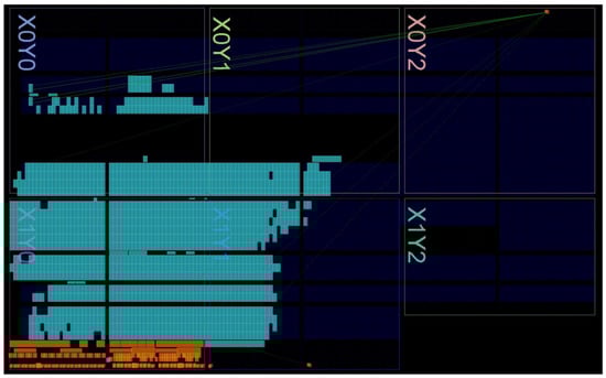
Figure 4.
Floorplan of the complete digital system implemented on the commercial XILINX ARTIX 7 FPGA-based board.
Table 3.
Used resources by the complete digital system implemented on the commercial XILINX ARTIX 7 FPGA-based board.
4. Experimental Validation and Results
Figure 5 shows the experimental setup employed to validate and characterize the developed insulin-glucose regulator based on the fully-hardware digital treatment decision controller. According to Figure 1, the VP SIMULINK model and the interface script have been implemented on MATLAB R2022a environment. On the contrary, the treatment decision controller has been designed using VIVADO 2020.2 and implemented using an Arty A7-35T development platform provided by Digilent that uses the XILINX FPGA Artix-7 model XC7A35TICSG324. Aim of the MATLAB script is to transmit/receive data to/from the FPGA board. Moreover, MATLAB elaborates and plots the results. The MATLAB environment runs on a laptop PC, physically connected to the FPGA-based hardware through an USB cable that is used to establish the JTAG connection and to power the board.
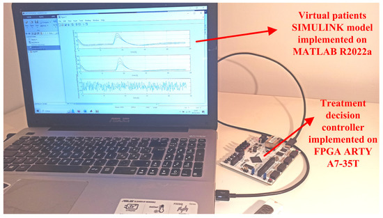
Figure 5.
Experimental setup of the developed insulin-glucose regulator based on the fully-hardware digital treatment decision controller. The MATLAB software environment runs on a laptop PC, the hardware treatment decision controller is implemented on the FPGA ARTY A7-35T.
The FPGA hardware architecture of the treatment decision controller of Figure 1 has been first validated in an open-loop operating condition obtained by excluding the VP in the block scheme of Figure 1.
In Panel (a) of Figure 6 are reported 144 quantized sample-data of the glucose concentration (i.e., in Equation (2)) taken every 10 min for a one-day duration of 24 h. These values have been first determined by simulating the treatment decision controller for an VP under the closed loop mode condition. It is worth noting that the glucose concentration increases in correspondence of VP meal intakes. The glucose concentration data have been used as the input of the treatment decision controller emulated by a SIMULINK model and the FPGA board. The calculated software and hardware data of the temporal variation of the insulin concentration by these two approaches are reported in Panel (b) of Figure 6. These values of the insulin concentration are the input signals of the digital insulin pump of Figure 1 under the closed-loop mode condition. The correctness and reliability of the operation of the decision controller simulated by the SIMULINK model and implemented on the FPGA board has been demonstrated by calculating the point-by-point relative error between the two sets of data shown in Panel (b) of Figure 6. The result of this calculation is reported in Panel (c) of Figure 6 showing that the corresponding relative error is always lower than ±1%.
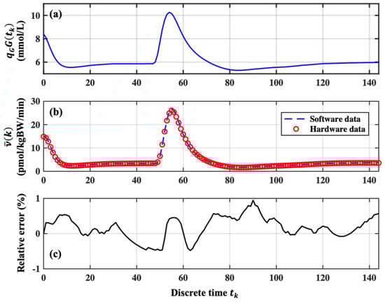
Figure 6.
Operation of the insulin-glucose regulator under open loop condition. Panel (a): Example of the variation of the VP glucose concertation in 144 steps taken every 10 min; Panel (b) Comparison between the software and hardware data achieved by emulating the treatment decision controller by the SIMULINK model and implemented by the FPGA board; Panel (c) the point-by-point relative errors between the two set of data reported in Panel (b).
The closed loop operating condition of the insulin-glucose regulator has been validated by using the quantized values of the glucose concentration of a sample of one hundred VPs in a feedback connection with the AP, each one presenting similar trends of glucose concentration with different maximum and minimum values.
To facilitate the discussion on the results of the test, the sample of the one hundred VPs has been reduced to only three VPs chosen as follows: considering the maximum and minimum glucose concentration peaks measured among all the one hundred VPs, P1 and P3 identify the VPs that reach the maximum glucose concentration equal to 11.3 mmol/L and 9.4 mmol/L, respectively; the third VP identified with P2, reaches a maximum glucose concentration equal to the average value among all the tested VPs. The variations of the glucose concentration and the corresponding values of the insulin concentration to be infused in the VP bodies determined by the treatment decision controller emulated by the SIMULINK model and implemented by the FPGA board are reported in Panel (a) and Panel (b) of Figure 7, respectively.
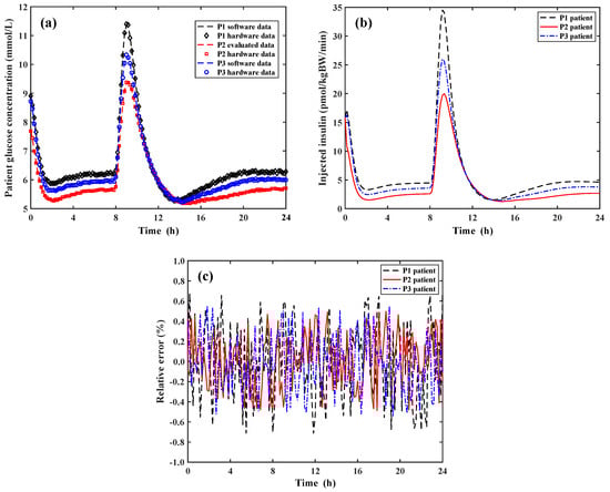
Figure 7.
Operation of the insulin-glucose regulator system under the close loop condition. Panel (a): Variation of the software and hardware data of the glucose concentration for the three VPs during a day; Panel (b): Insulin concentration infused in the VP bodies determined by the treatment decision controller implemented by the FPGA board; Panel (c) Point-by-point relative error between the software and hardware data of Panel (a).
According to Panel (a) of Figure 6, Panel (a) of Figure 7 reports the quantized sample-data of the glucose concentration for the three VPs taken every 10 min for a total duration of 24 h. In the closed loop condition, it is important to compare in Panel (a) of Figure 7 the resulting glucose concentration after the insulin infusion in the VP bodies calculated by using the full SIMULINK approach (i.e., both VP and AP are simulated by the SIMULINK model) and by the software/hardware approach (i.e., the SIMULINK model simulates the VP and the FPGA board implements the AP system). As before stated, the increase of the glucose concentration corresponds to a period during which the three VPs have eaten a meal. Panel (b) of Figure 7 shows the values of the concentration of the infused insulin determined by the implemented FPGA hardware treatment decision controller. As shown, the rate of the infused insulin concentrations exactly follows that one of the glucose concentrations for the three VPs. It is important to note that the postprandial values of the glucose concentration for each VP returns to be equal to the pre-prandial ones demonstrating the good operation of the developed insulin-glucose regulator. Finally, Panel (c) of Figure 7 reports the point-by-point relative errors between the software and hardware data of the VP glucose concentration of Panel (a) achieved by the treatment decision controller emulated by the SIMULINK model and implemented by the FPFA board. The calculated relative error is always lower than ±0.7% so demonstrating the correctness of the operation performed by the FPGA hardware treatment decision controller making it a solution suitable in real biomedical scenarios and applications.
5. Conclusions
The paper describes in detail the implementation on an FPGA board Xilinx Artix 7 of an insulin-glucose regulator for type 2 diabetic patients that operates by measuring only the glucose concentration in the patient blood. All the operations enclosed in the theoretical model recognized by the U.S. Food and Drug Administration for the pre-clinical validation of glucose control strategies has been transferred and implemented on the FPGA board and suitably processed by the developed hardware architecture. This results in a software-free, fully-hardware operation of the insulin-glucose regulator paving the root for specific design of microelectronic architectures to replace the general-purpose programmable hardware components employed in other reported similar solutions. The developed prototype has been used to evaluate the performances of the proposed architecture in open-loop condition where only the insulin-glucose controller is operating and in closed-loop condition for which the insulin-glucose controller acts as the artificial pancreas of virtual patients simulated in SIMULINK. The validation of the proposed system has been performed by using one hundred virtual patients as a clinical sample that, during a day, present similar trends of the variations of the glucose concentration reaching different maximum and minimum values when eating meals. The insulin-glucose regulator performances in closed-loop operating conditions have been obtained by employing the above-mentioned theoretical model developed in SIMULINK to simulate the virtual patients connected to the controller implemented on the FPGA board. The reported experimental results both in open-loop and closed-loop conditions show a relative error less than ±1% compared to what is expected from the theoretical model. The proposed insulin-glucose regulator elaborates the input values of the virtual patient glucose concentration and determines the corresponding insulin concentration to be infused in about 1.1 μs and operates with a total power consumption of about 36 mW. In order to minimize the system power consumption, dimension and overcome the present hardware limitations and complexity in using an FPGA board, work is in progress in designing the integrated microelectronic System-on-Chip (or Lab-on-Chip) of the proposed solution. This represents the key step to apply the integrated fully-hardware solution in biomedical portable, wearable, and implantable applications.
Author Contributions
Conceptualization, M.D.F., S.D.G. and P.P.; Data curation, G.D.P.S., A.D.M., M.F., E.P. and M.D.F.; Formal analysis, M.D.F., S.D.G. and P.P.; Funding acquisition, A.D.M.; Investigation, G.D.P.S. and A.D.M.; Methodology, M.D.F., S.D.G. and P.P.; Project administration, A.D.M.; Resources, A.D.M.; Software, M.D.F.; Supervision, A.D.M., M.F. and E.P.; Validation, G.D.P.S., M.F. and E.P.; Visualization, G.D.P.S.; Writing—original draft, A.D.M.; Writing—review & editing, G.D.P.S., A.D.M., M.F., E.P., M.D.F., S.D.G. and P.P. All authors supplied the overall system specifications equally providing the contribution to this work. All authors have read and agreed to the published version of the manuscript.
Funding
This work has been funded by the European Union—Next Generation EU, under the Italian Ministry of University and Research (MUR), National Innovation Ecosystem grant ECS00000041—VITALITY—CUP E13C22001060006.
Data Availability Statement
Data are contained within the article.
Conflicts of Interest
The authors declare no conflict of interest.
References
- Kaiser, U.B.; Mirmira, R.G.; Stewart, P.M. Our response to COVID-19 as endocrinologists and diabetologists. J. Clin. Endocrinol. Metab. 2020, 105, 1299–1301. [Google Scholar] [CrossRef] [PubMed]
- Ogurtsova, K.; da Rocha Fernandes, J.D.; Huang, Y.; Linnenkamp, U.; Guariguata, L.; Cho, N.H.; Cavan, D.; Shaw, J.E.; Makaroff, L.E. IDF diabetes atlas: Global estimates for the prevalence of diabetes for 2015 and 2040. Diabetes Res. Clin. Pract. 2017, 128, 40–50. [Google Scholar] [CrossRef]
- Schofield, J.; Leelarathna, L.; Thabit, H. COVID-19: Impact of and on diabetes. Diabetes Ther. 2020, 11, 1429–1435. [Google Scholar] [CrossRef] [PubMed]
- Guo, W.; Li, M.; Dong, Y.; Zhou, H.; Zhang, Z.; Tian, C.; Qin, R.; Wang, H.; Shen, Y.; Du, K.; et al. Diabetes is a risk factor for the progression and prognosis of COVID-19. Diabetes/Metab. Res. Rev. 2020, 36, e3319. [Google Scholar] [CrossRef] [PubMed]
- Beneyto, A.; Bertachi, A.; Bondia, J.; Vehi, J. A new blood glucose control scheme for unannounced exercise in type 1 diabetic subjects. IEEE Trans. Control Sys. Technol. 2020, 28, 593–600. [Google Scholar] [CrossRef]
- Gondhalekar, R.; Dassau, E.; Doyle III, F.J. Velocity-weighting & velocity-penalty mpc of an artificial pancreas: Improved safety & performance. Automatica 2018, 91, 105–117. [Google Scholar] [CrossRef] [PubMed]
- Kovàcs, L.; Eigner, G.; Czakó, B.; Siket, M.; Tar, J.K. An opportunity of using robust fixed-point transformation-based controller design in case of type 1 diabetes mellitus. In Proceedings of the First International Conference on Societal Automation, Krakow, Poland, 4–6 September 2019. [Google Scholar] [CrossRef]
- Magni, L.; Raimondo, D.M.; Dalla Man, C.; De Nicolao, G.; Kovatchev, B.; Cobelli, C. Model predictive control of glucose concentration in type I diabetic patients: An in silico trial. Biomed. Signal Process. Control 2009, 4, 338–346. [Google Scholar] [CrossRef]
- Messori, M.; Incremona, G.P.; Cobelli, C.; Magni, L. Individualized model predictive control for the artificial pancreas. IEEE Control Syst. Mag. 2018, 38, 86–104. [Google Scholar] [CrossRef]
- Clarke, F.H.; Ledyaev, Y.S.; Sontag, E.D.; Subbotin, A.I. Asymptotic controllability implies feedback stabilization. IEEE Trans. Autom. Control 1997, 42, 1394–1407. [Google Scholar] [CrossRef]
- Di Ferdinando, M.; Pepe, P.; Borri, A. On practical stability preservation under fast sampling and accurate quantization of feedbacks for nonlinear time-delay systems. IEEE Trans. Autom. Control 2021, 66, 314–321. [Google Scholar] [CrossRef]
- Hetel, L.; Fiter, C.; Omran, H.; Seuret, A.; Fridman, E.; Richard, J.P.; Niculescu, S.I. Recent developments on the stability of systems with aperiodic sampling: An overview. Automatica 2017, 76, 309–335. [Google Scholar] [CrossRef]
- Pepe, P. On stability preservation under sampling and approximation of feedbacks for retarded systems. SIAM J. Control Optim. 2016, 54, 1895–1918. [Google Scholar] [CrossRef]
- Borri, A.; Pepe, P.; Loreto, I.D.; Di Ferdinando, M. Finite dimensional periodic event-triggered control of nonlinear time-delay systems with an application to the artificial pancreas. IEEE Control Syst. Lett. 2021, 5, 31–36. [Google Scholar] [CrossRef]
- Di Ferdinando, M.; Pepe, P.; Palumbo, P.; Panunzi, S.; De Gaetano, A. Robust global nonlinear sampled-data regulator for the glucose-insulin system. In Proceedings of the 2017 IEEE 56th Annual Conference on Decision and Control (CDC), Melbourne, Australia, 12–15 December 2017. [Google Scholar] [CrossRef]
- Di Ferdinando, M.; Pepe, P.; Di Gennaro, S.; Palumbo, P. Sampled data static output feedback control of the glucose-insulin system. In Proceedings of the IFAC World Congress, Berlin, Germany, 12–17 July 2020. [Google Scholar] [CrossRef]
- Di Ferdinando, M.; Pepe, P.; Gennaro, S.D.; Borri, A.; Palumbo, P. Quantized sampled-data static output feedback control of the glucose-insulin system. Control Eng. Pract. 2021, 112, 104828. [Google Scholar] [CrossRef]
- De Marcellis, A.; Di Patrizio Stanchieri, G.; Palange, E.; Faccio, M.; Constandinou, T.G. An Ultra-Wideband-Inspired system-on-chip for an optical bidirectional transcutaneous biotelemetry. In Proceedings of the IEEE BioCAS, Cleveland, OH, USA, 17–19 October 2018. [Google Scholar] [CrossRef]
- Ananthanarayanan, V.; Haridas, T.P.M.; Naveen, R.; Rajeswari, A. Reliable and affordable embedded system solution for continuous blood glucose maintaining system with wireless connectivity to blood glucose measuring system. In Proceedings of the Amrita International Conference of Women in Computing, Coimbatore Campus, Amrita Vishwa Vidyapeetham, Coimbatore, India, 9–11 January 2013. [Google Scholar]
- Jeyapriya, S.; Ramalakshmi, R. Glucose monitoring and control in diabetes using GSM and automatic insulin injector system for human bodies. In Proceedings of the 2017 IEEE International Conference on Intelligent Techniques in Control, Optimization and Signal Processing (INCOS), Srivilliputtur, India, 23–25 March 2017. [Google Scholar] [CrossRef]
- Chandrasekhar, A.; Saini, D.; Padhi, R. An android phone based artificial pancreas system for type-1 diabetic patients. In Proceedings of the 2021 IEEE 9th Region 10 Humanitarian Technology Conference (R10-HTC), Bangalore, India, 30 September–2 October 2021. [Google Scholar] [CrossRef]
- Di Patrizio Stanchieri, G.; Battisti, G.; De Marcellis, A.; Faccio, M.; Palange, E.; Constandinou, T.G. A New Multilevel Pulsed Modulation Technique for Low Power High Data Rate Optical Biotelemetry. In Proceedings of the 2021 IEEE Biomedical Circuits and Systems Conference (BioCAS), Berlin, Germany, 7–9 October 2021. [Google Scholar] [CrossRef]
- Joshi, A.M.; Jain, P.; Mohanty, S.P. iglu 3.0: A secure noninvasive glucometer and automatic insulin delivery system in IoMT. IEEE Trans. Consum. Electron. 2022, 68, 14–22. [Google Scholar] [CrossRef]
- Nomikos, K.; Papadimitriou, A.; Stergiopoulos, G.; Koutras, D.; Psarakis, M.; Kotzanikolaou, P. On a security-oriented design framework for medical IoT devices: The hardware security perspective. In Proceedings of the 2020 23rd Euromicro Conference on Digital System Design (DSD), Kranj, Slovenia, 26–28 August 2020. [Google Scholar] [CrossRef]
- Di Patrizio Stanchieri, G.; De Marcellis, A.; Faccio, M.; Palange, E. An FPGA-based architecture of true random number generator for network security applications. In Proceedings of the 2018 IEEE International Symposium on Circuits and Systems (ISCAS), Florence, Italy, 27–30 May 2018. [Google Scholar] [CrossRef]
- Di Patrizio Stanchieri, G.; Saleh, M.; Sciulli, M.; De Marcellis, A.; Ibrahim, A.; Valle, M.; Faccio, M.; Palange, E. FPGA-based tactile sensory feedback system with optical fiber data communication link for prosthetic applications. In Proceedings of the 2019 26th IEEE International Conference on Electronics, Circuits and Systems (ICECS), Genova, Itay, 27–29 November 2019. [Google Scholar] [CrossRef]
- Di Patrizio Stanchieri, G.; De Marcellis, A.; Battisti, G.; Faccio, M.; Palange, E.; Constandinou, T.G. A multilevel synchronized optical pulsed modulation for high efficiency biotelemetry. IEEE Trans. Biomed. Circuits Syst. 2022, 16, 1313–1324. [Google Scholar] [CrossRef] [PubMed]
- Li, P.; Yu, L.; Fang, Q.; Lee, S. A simplification of Cobelli’s glucose–insulin model for type 1 diabetes mellitus and its FPGA implementation. Med. Biol. Eng. Comput. 2016, 54, 1563–1577. [Google Scholar] [CrossRef] [PubMed]
- Di Patrizio Stanchieri, G.; De Marcellis, A.; Faccio, M.; Palange, E.; Di Ferdinando, M.; Di Gennaro, S.; Pepe, P. On the FPGA-Based Hardware Implementation of Digital Glucose Regulators for Type 2 Diabetic Patients. In Proceedings of the 2023 IEEE 36th International Symposium on Computer-Based Medical Systems (CBMS), L’Aquila, Italy, 22–24 June 2023. [Google Scholar] [CrossRef]
- Palumbo, P.; Panunzi, S.; De Gaetano, A. Qualitative behavior of a family of delay differential models of the glucose insulin system. Discret. Contin. Dynam. Syst.—B 2007, 7, 399–424. [Google Scholar] [CrossRef]
- Panunzi, S.; Palumbo, P.; De Gaetano, A. A discrete single delay model for the intra-venous glucose tolerance test. Theor. Biol. Med. Model. 2007, 4, 35. [Google Scholar] [CrossRef]
- Dalla Man, C.; Rizza, R.; Cobelli, C. Meal simulation model of the glucose-insulin system. IEEE Trans. Biomed. Eng. 2007, 54, 1740–1749. [Google Scholar] [CrossRef]
- Kovatchev, B.P.; Breton, M.D.; Dalla Man, C.; Cobelli, C. In silico model and computer simulation environment approximating the human glucose/insulin utilization. Food Drug Adm. Master File MAF 2008, 1521, 338–346. [Google Scholar] [CrossRef]
- Di Ferdinando, M.; Pepe, P.; Palumbo, P.; Panunzi, S.; De Gaetano, A. Semi-global sampled-data dynamic output feedback controller for the glucose-insulin system. IEEE Trans. Control Syst. Technol. 2020, 28, 16–32. [Google Scholar] [CrossRef]
- Palumbo, P.; Pizzichelli, G.; Panunzi, S.; Pepe, P.; De Gaetano, A. Model-based control of plasma glycemia: Tests on populations of virtual patients. Math. Biosci. 2014, 257, 2–10. [Google Scholar] [CrossRef] [PubMed]
- Harvey, R.A.; Dassau, E.; Zisser, H.; Seborg, D.E.; Jovanovic, L.; Doyle, F.J., III. Design of the health monitoring system for the artificial pancreas: Low glucose prediction module. J. Diabetes Sci. Technol. 2012, 6, 1345–1354. [Google Scholar] [CrossRef] [PubMed]
Disclaimer/Publisher’s Note: The statements, opinions and data contained in all publications are solely those of the individual author(s) and contributor(s) and not of MDPI and/or the editor(s). MDPI and/or the editor(s) disclaim responsibility for any injury to people or property resulting from any ideas, methods, instructions or products referred to in the content. |
© 2024 by the authors. Licensee MDPI, Basel, Switzerland. This article is an open access article distributed under the terms and conditions of the Creative Commons Attribution (CC BY) license (https://creativecommons.org/licenses/by/4.0/).