Article

Tissue Ablation Using Irreversible Electrolytic Electroporation with Reduced Voltage

1
Department of Biomedical Engineering, School of ICT Convergence Engineering, College of Science & Technology, Konkuk University, Chungju-si 27478, Republic of Korea
2
Department of Medicinal Biosciences, Research Institute for Biomedical & Health Science, College of Biomedical and Health Science, Konkuk University, Chungju-si 27478, Republic of Korea
3
Biomedical Engineering Research Center, Asan Institute for Life Sciences, Asan Medical Center, Olympic-ro, Seoul 05505, Republic of Korea
4
The Standard Co., Ltd., Gunpo-si 15880, Republic of Korea
5
Department of Mechatronics Engineering, School of ICT Convergence Engineering, College of Science & Technology, Konkuk University, Chungju-si 27478, Republic of Korea
*
Author to whom correspondence should be addressed.
Electronics 2023, 12(13), 2916; https://doi.org/10.3390/electronics12132916
Submission received: 26 May 2023 / Revised: 26 June 2023 / Accepted: 30 June 2023 / Published: 3 July 2023
(This article belongs to the Special Issue Emerging Electronic Technologies for Biomedical Applications)

Abstract

:
Thermal tissue ablation may damage surrounding healthy tissue and cause pain. In this study, tissue ablation with the sequential application of electrical energy-inducing irreversible electroporation (IRE) and electrolysis (EL) (IRE + EL = IREEL) was investigated. An IREEL device was designed to control five output pulse parameters: voltage level (VL), pulse width (PW), pulse interval (PI), pulse number (PN), and pulse tail time (PTT). IREEL experiments were conducted on vegetable tissue. The results indicated that by increasing the VL and PTT, the ablation area increased, whereas the impedance was reduced significantly. Almost no ablation area was observed when only EL or IRE at 500 V and 1000 V, respectively, were applied. The ablation area observed with IRE alone at 1500 V was defined as 100%. In the case of IREEL at 500 V and 1000 V, ablation was induced even with the use of micro-second level PTT, and ablation areas of 91% and 186% were achieved, respectively. For IREEL at a voltage of 1500 V, the ablation area expanded to 209% and the maximum temperature was 48.7 °C, whereas the temperature did not exceed 30 °C under other conditions. A change in pH was also observed in an agar-gel phantom experiment which was conducted to examine and confirm whether IREEL induced electrolysis. IREEL was able induce ablation at low voltages owing to the synergistic effect of applying IRE and EL sequentially. Moreover, the ablation areas at high voltages could be increased compared to the areas observed when IRE and EL were applied independently.

1. Introduction

Currently, different tissue ablation techniques, including radiofrequency ablation (RFA) based on radiofrequency waves [1], high-intensity focused ultrasound [2], laser interstitial thermal therapy using heat emitted from a laser [3], and carbon dioxide (CO2)-based cryoablation [4], have been developed. These approaches are based on the heating or cooling of tissues. Among these, RFA is a minimally invasive technique delivering electrical energy to target tissues by applying electrical currents using a needle electrode or catheter. Additionally, RFA allows induced ablation zone prediction; thus, this technique is typically used in clinical therapy and for ablating abnormal tissues or tumors [1,5]. However, as thermal ablation can cause necrosis of all tissues and cells in an area where thermal energy is generated, normal or benign tissues are also affected, resulting in complications such as injury to blood vessels, scarring, pulmonary vein stenosis and restenosis, infection, and bleeding due to puncture [6,7]. Therefore, tissue ablation using a non-thermal strategy known as electroporation is being actively investigated [8,9,10]. In electroporation, a high voltage is applied to a target tissue for a short duration, during which the pores of the cell membrane briefly open, resulting in a transient increase in permeability. Electroporation can be manifested in two forms—reversible and irreversible (IRE)—based on cellular changes. Thus, the technique is suitable for a wide range of applications in medicine and electro-manipulation, including the insertion of proteins and molecules, gene transfer and drug delivery, and apoptotic cell death [11,12,13,14]. Similar to RFA, electroporation relies on electromagnetic phenomena, enabling ablation prediction through modeling and simulation to provide minimally invasive treatments [15,16,17]. IRE is primarily used for tissue ablation because it induces apoptosis in target tissues, although physical bleeding during the electrode insertion process and vasoconstriction after applying electric high-voltage may accompany the treatment [18], and it enables selective target destruction with minimal or no damage to the surrounding normal tissues. However, because this method involves applying high voltages of approximately several kilovolts, strict treatment protocols are necessary to avoid ventricular or atrial fibrillation and muscle contraction. Another limitation of IRE is pain induction [19,20,21,22]. According to recent reports, the effective tissue ablation area using IRE can be less than 3 cm at maximum. Thus, high-voltage applications or the use of multiple electrode configurations should be considered to increase the ablation zone [23,24,25,26].
Recently, studies have attempted to address the limitations of IRE based on various approaches such as applying a pulse width in the range of nano-seconds, utilizing a high-frequency bipolar pulse [27,28], applying combinations of high- and low-voltage IRE pulses [29,30], applying various high-voltages and changes in tissue temperature [31,32], and using only low DC voltages [33,34]. Additional strategies involve combining radiofrequency ablation (RFA) and irreversible electroporation (IRE) [35,36] and combining electroporation and electrolysis (EL) using a single exponential decay wave with only an initial high voltage [37,38,39]. However, few studies have focused on reducing the voltage applied during IRE. Therefore, this study investigated a new energy transfer pulse-shaped waveform capable of increasing the ablation area while lowering the IRE voltage. A square pulse for conventional IRE and an exponential decay waveform for EL were sequentially applied to tissues to examine the synergistic effects of the two mechanisms (IRE + EL = IREEL) in tissue ablation. To realize the goal of this study, we designed and developed an irreversible electrolytic electroporator (IREEL) to quantify the changes in the ablation area, impedance, temperature, and pH according to the pulse parameters.

2. Materials and Methods

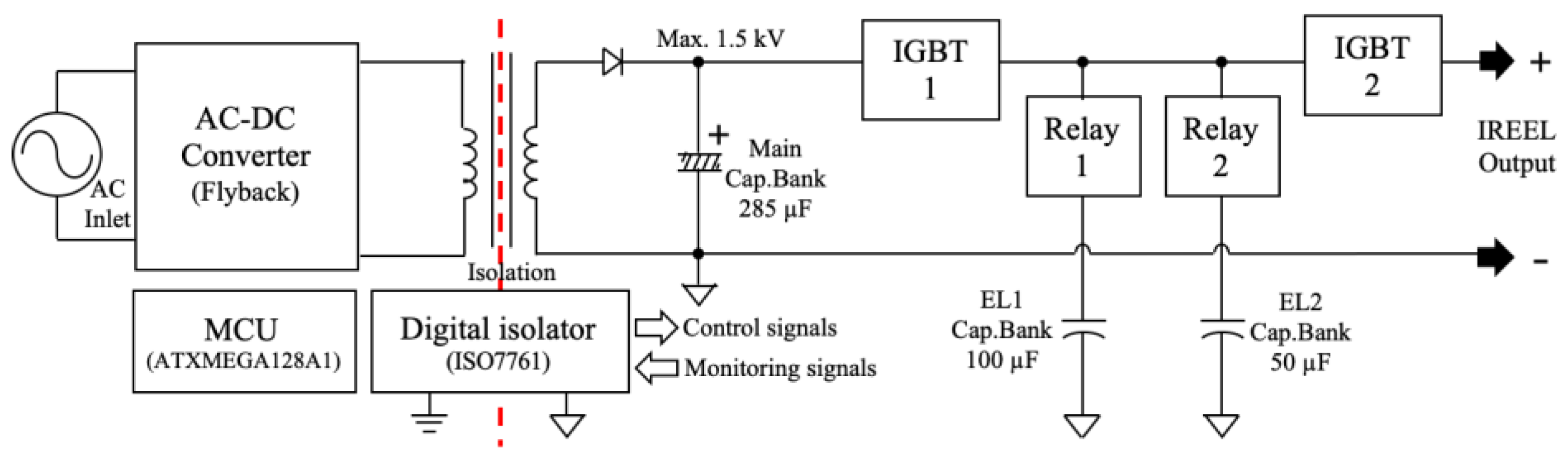
2.1. Development of the IREEL

To implement the IRE and EL operations, we developed an IREEL electroporator to generate pulse-shaped and exponential decay waveforms as outputs. The developed device had power, output, and control units, as shown in Figure 1.
The power unit received a 220 V alternative current (AC) as an external input voltage. For the high-voltage setup, a 24 V direct current (DC) was generated, while 5 V and 12 V DCs were generated to control the overall system. A flyback topology from the switched-mode power supply was used for the high-voltage setup to generate high voltages ranging from 100 to 1500 V in intervals of 100 V. The generated electrical energy was stored in electrolysis capacitor 1 (EL1), electrolysis capacitor 2 (EL2), and main capacitor banks of 100, 50, and 285 μF, respectively. The energy stored in all the capacitor banks was used to generate the square pulse output of the IRE, whereas that stored in the EL1 and EL2 capacitor banks was used simultaneously or individually to generate the single exponential decay waveform of the EL, depending on the selected time constant. The setup allowed for four different time constants to be set as required.
The output unit included two insulated gate bipolar transistors (IGBTs) (IXBX25N205) (IXYS Corp., Milpitas, CA, USA). The operating sequence of the output and pulse parameters controlled in the experimental setup is depicted in Figure 2. For the IRE pulse outputs, both IGBT 1 and 2 were turned on simultaneously. Subsequently, according to the set pulse width (PW) (i.e., the time of the high level of the output pulse), pulse number (PN) (i.e., the number of output pulses), and pulse interval (PI) (i.e., the time between the rising edge of a pulse and the rising edge of the next pulse), IGBT 2 was turned on or off. For generating the EL waveforms, IGBT 1 was turned off only to use the energy stored in the EL1 and EL2 capacitor banks. In contrast, IGBT 2 was turned on only for a set duration of time, which is herein referred to as the pulse tail time (PTT), i.e., the time when the exponential decay waveform was delivered to tissue. Thus, the experimental setup allowed for the selective output of the following different waveforms: IREEL (the consecutive output of IRE and EL), IRE alone, or EL alone.
The control unit comprised a microcontroller (ATXMEGA128A1) (Microchip Technology Inc., Chandler, AZ, USA) which controlled the total operation of the device and the five pulse parameters. The user interface was configured with a character liquid crystal display, four buttons, and an encoder. For safety, galvanic isolation was provided between the low- and high-voltage parts of the circuit. The control and monitoring signals were transmitted using a digital isolator (ISO7761) (Texas Instruments, Dallas, TX, USA).

2.2. TTC Test on a Potato as a Tissue Phantom

Potatoes are typically used as tissue phantoms for pilot experiments, particularly for electroporation, owing to their relative ease of use, preliminary test convenience, absence of ethical issues, low cost, and minimal time requirements [40,41]. To minimize the variability due to the inhomogeneity of potato tissues, potatoes of similar size, temperature, and impedance conditions were selected for the experiment. The largest outer diameter of the potatoes was limited to 8–10 cm. The potatoes, stored at 0–10 °C, were exposed to ambient temperature for 12 h before starting the experiment and were cut into slices of 10 mm thicknesses. Of the selected potatoes, only those with impedances within 6 ± 0.8 kΩ were used in the experiment. A low-frequency impedance analyzer (HP4192A) (Keysight Technologies, Santa Rosa, CA, USA) was used to measure the impedance at 10 Hz. For impedance measurements and pulse energy applications, a stainless-steel needle electrode with a 2 mm diameter was inserted into the potatoes to a depth of 10 mm. A triphenyl-tetrazolium chloride (TTC; Sigma-Aldrich, St. Louis, MO, USA) test was utilized as a cell viability assay after energy application. TTC is a redox indicator typically used in biochemistry to detect cellular respiration [40]. When dehydrogenase, produced as a result of mitochondrial respiration in cells, and TTC are combined, TTC turns red. Otherwise, if the cell activity is minimal or in the case of cell death, TTC remains colorless. Thus, cell viability and activity can be easily determined. For the TTC staining, a reagent of 0.5% w/v was prepared by adding 5 g of TTC to 1000 mL of distilled water.
The developed IREEL electroporator was used under pulse parameter conditions of PW = 10 μs, PI = 1000 μs, PN = 8, and variable PTTs of 0, 400, 800, 1600, and 3200 μs, and variable voltages of 500, 1000, and 1500 V were applied. For PTT = 0 μs, the output energy generated square pulses only, which were similar to those of the conventional IRE output. In contrast, for PN = 0, the output energy generated exponential decay waveforms only. The experiments were conducted under 18 different conditions and with five replicates for each experimental condition; thus, a total of 90 potato slices were used.

2.3. Quantification of the Biological Changes

The temperature, impedance, and ablation area changes were quantified to examine and analyze the changes based on the output waveforms. The temperatures were recorded using a thermal infrared camera (One Pro LT) (Teledyne FLIR LLC, Wilsonville, OR, USA), while the impedances were measured before the experiment and immediately after energy application, without removing the needle electrode, as shown in Figure 3. To calculate the ablation areas, MATLAB (MathWorks, Natick, MA, USA) was used.
After applying energy to the potato slices, the electrode was removed completely, and the potato slices were placed on a Petri dish containing the TTC staining solution. After 6 h of staining, changes were observed as the potatoes presented red and white areas. Red, green, and blue (RGB) information from the color images was used for grayscale conversion. The RGB images were converted to two-level indexed stages to perform the binarization. After filtering into Gaussian-weighted images, the ablation areas were calculated in pixel units [42].
Furthermore, 0.5% Bacto-agarose, 0.2% NaCl, and 1% water pH liquid indicator (pH Test Drops, Parkton, NC, USA) were mixed in distilled water and then boiled for 5 min in a microwave oven. Afterward, the solution was solidified for 30 min at room temperature to prepare an agar-gel phantom to observe the EL’s effect. Changes in the pH levels of the phantoms resulting from the PTT changes were examined under the aforementioned needle electrode conditions.

2.4. Statistical Analysis

The results, performed 5 times for each experimental condition, were calculated as means ± standard deviations. In addition, significance was analyzed using a two-tailed paired Student’s t-test for each condition (* p < 0.05, ** p < 0.01, and *** p < 0.001). Statistical analysis was performed using Microsoft Office 365 Excel software (Microsoft Co., Ltd., Redmond, WA, USA).

3. Results

3.1. Output Waveforms of the IREEL

Figure 4 presents the IREEL electroporator and the output voltage and output current waveforms at a resistive load of 120 Ω. The output was obtained using a digital phosphor oscilloscope (TDA3044B) (Tektronix Inc., Beaverton, OR, USA) with a differential probe (P5201A) (Tektronix Inc., Beaverton, OR, USA) to measure the voltage and a TCP305A (Tektronix Inc., Beaverton, OR, USA) probe to measure the current. The main control parameter, the maximum output voltage level (VL), was set at 1500 V, and a minimum PW of 10 μs was used. The voltage and current outputs for a wide range of values of the PI, PN, and PTT were obtained. The design of the IREEL electroporator was verified to generate the IRE and EL energy output waveforms individually and sequentially. The decreases in the PTT with the time constant (τ = RC) were determined by the selective connection of the appropriate EL capacitor banks to the resistive load.

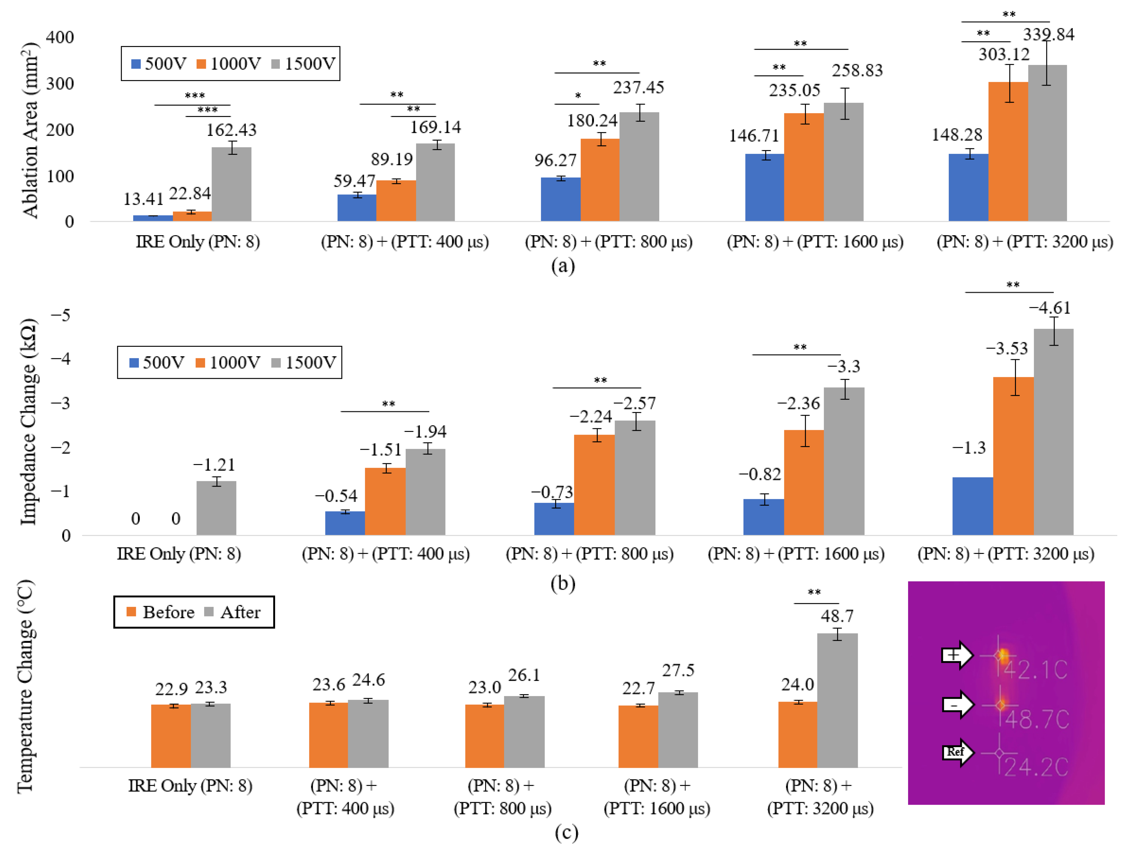
3.2. Changes in the Ablation Areas with PTT

The IREEL experiments were performed using potato slices. Figure 5 presents the potato slices stained red using TTC. Apoptosis was induced in the white areas of the potato slices. The apoptotic area was observed to increase with the VL and PTT. The ablation areas, impedances, and temperature changes were recorded. The results are presented in Figure 6a–c, respectively. A small ablation area around the electrode was observed for only the IRE application at 500 and 1000 V. Moreover, the ablation area increased accordingly when the voltage was increased. For IREEL, where the EL was applied immediately after IRE, the ablation area increased with the PTT, even at a low voltage (Figure 6a). Among the IREEL measurement conditions, the ablation areas for 1600 and 3200 μs PTTs with both IRE and EL applied at 500 V were similar to those for 1500 V with only the IRE application. For IRE and EL applied at 1500 V and 3200 μs PTT, respectively, the ablation area was more than double that obtained with only IRE at 1500 V. Table 1 lists the percentages of the ablation areas relative to the ablation areas produced at 1500 V IRE under each measurement condition. The decreases in impedance demonstrated a positive correlation with the ablation area as the VL and PTT increased, except for the cases of 500 and 1000 V with only the IRE application (Figure 6b). Regarding the temperature, only the highest temperatures observed before and after the experiment under the condition of VL = 1500 V were analyzed (Figure 6c). For IREEL at 1500 V and 3200 μs PTT, the temperature increased from 24.0 °C before the experiment to approximately 48.7 °C after the experiment. Except for this specific case, the temperature increments were approximately 5 °C or less under all measurement conditions of the experiment.

3.3. Changes in pH with the PTT

Figure 7 presents images of the redox reactions in the agar-gel phantoms with a dissolved pH indicator. The results shown correspond to 500 V and PTTs of 400, 800, 1600, and 3200 μs. Before the experiment, a uniform color indicating a pH value of seven was observed. After the experiment, the colors indicated pH values of five and eight at the positive and negative electrodes, indicating oxidation and reduction, respectively. When only IRE was applied to the phantom in the same Petri dish, the redox reaction was not observed (the inset box with a dotted line boundary shown in Figure 7).

4. Discussion

In this study, we investigated the ablation of a tissue phantom with the simultaneous application of a square pulse energy output from IRE and an exponential decay energy waveform from EL. An IREEL electroporator was designed, and the setup was used to quantify the ablation area, impedance, and temperature changes for sliced potato samples. Additionally, changes in pH were observed using an agar-gel phantom.
Notably, the developed IREEL electroporator consisted of power, output, and control units, and the experimental setup had a total of five controllable pulse parameters. The following is a summary of the measurement conditions that allowed for wide-ranged control: VLs ranging from 100 to 1500 V in increments of 100 V, PWs ranging from 10 to 500 μs in increments of 10 μs, PIs ranging from 10 μs to 5 ms in increments of 10 μs, PNs ranging from 1 to 999, and PTTs ranging from 1 to 1000 ms in increments of 1 ms. In addition, the decay time constant of the exponential wave could be controlled.
The experimental results for the sliced potato phantoms indicated that the ablation area increased when eight square pulses of IRE and a micro-second level EL energy were applied consecutively compared to when IRE was applied alone with the same number of square pulses. When a milli-second level of EL energy was used, the ablation area increased by more than two times. When the temperature change was observed using a thermal infrared camera for the longest PTT of 3200 μs, the temperature change ΔT was 24.7 °C after the experiment, reaching a maximum temperature of 48.7 °C. A study on thermal injuries to tissue due to IRE ablation reported that thermal damage was induced when a temperature of 54 °C or higher persisted for 10 s [43]. In this study, the temperature rise was lower than that recorded in the previous study, and the temperature returned to the base temperature of the potato before the experiment within 3 s. For PTT values lower than 3200 μs, the maximum temperature change was within approximately 5 °C. No temperature increments of more than 30 °C from the base temperature were observed. Additionally, as the ablation area increased with the PTT, the developed IREEL electroporator essentially induced non-thermal ablation, which further increased the efficiency. These results suggested that if the developed system were to be applied to other types of tissues, increases in the ablation areas could be achieved while controlling thermal damage to the tissues. Studies on the clinical application of IRE techniques have reported that the possibility of ventricular or atrial fibrillation and muscle contraction must be monitored carefully when high voltages are used during treatment owing to the possibility of additional undesirable consequences such as pain [19,20,21,22]. Thus, studies have been conducted to address these problems, including increasing the frequency with a nano-second level PW (H-FIRE) [19,20,24,28], applying a bipolar rectangular pulse [19,44], and optimizing the IRE electrode configuration, considering its shape and material [25,26]. However, these methods resulted in smaller ablation areas than conventional IRE owing to bipolar cancellation. Our results indicated that almost no ablation was induced when only IRE and EL were applied individually at low voltages. However, for IREEL, with a combination of IRE and EL under the same voltage condition, the ablation area was slightly smaller or increased to approximately 1.8 times when the PTT was 800 or ≥1600 μs, respectively, compared to the ablation area for IRE applied at a voltage of 1500 V. These results indicated that with the IREEL approach when energy is applied with electrolysis at low-voltage IRE, ablation can be induced owing to the synergistic effect of the two mechanisms. However, cell death by IREEL may be induced owing to the IRE-induced pore opening of the cell membrane, promoting the formation of a cytotoxic environment [38,45] from the subsequent change in pH due to the EL. The changes in pH by IREEL were observed using the agar-gel phantom. The impedance was observed to decrease under all experimental conditions except for IRE at 500 and 1000 V without EL. Additionally, the decrease in impedance was positively correlated with the change in the ablation area. A minimal or no ablation area was observed when the impedance was not changed. These results were consistent with previous findings related to electroporation [9,10,11,12,21,24,46,47].
The electroporation technique is being tried as an alternative to cancer treatment in clinical practice because it is possible to selectively ablate malignant tissue with a minimally invasive, non-thermal treatment while predicting the ablation area through simulation. However, the variability in the treatment effect was high, the system was complex, and the risk of using high voltage was also inherent. Recently, with the development of high-voltage power semiconductor technologies and parts while simplifying the configuration of the systems, these treatments have become safe for the human body, and it is possible to generate various electric pulses, and thus, studies are carrying out new pulse shapes [44]. In this paper, a study was conducted on whether the voltage required for ablation could be lowered when an exponential decay waveform was consecutively applied after applying an IRE using only several square pulses, which have been traditionally used. As a result of the experiment, it was confirmed that nearly the same ablation area was generated even when the voltage was lowered three times when IREEL was used compared to the results of applying IRE only and electrolysis only (Table 1). These results will be applicable to various parts of the body where IRE cannot be applied due to muscle contraction and cardiac fibrillation. As the voltage of the IREEL was increased, the ablation area was approximately doubled, and so it can be considered to be used for precise surgical planning. In addition, studies on cancer treatments for animals have recently begun to increase. Since most animals are smaller than humans, it is not possible to apply IRE, but the developed system and the electric parameters of IREEL can be applied to the development of treatment techniques.

5. Conclusions

In conclusion, this study verified that ablation could be performed even at low voltages, and the ablation area could be significantly increased at high voltages using IREEL, which combines IRE and EL. Thus, IREEL can be applied in cancer treatments, muscle twitches, and small animal in vivo experiments related to electroporation. However, in vivo or ex vivo studies with various types of animal tissues other than the potato tissue used in this study must be conducted for such expanded applications. Furthermore, the EL waveform considered in this study was sequentially applied after applying the IRE pulse. Therefore, additional in-depth comparative studies at the cellular level targeting Huh-7, glioblastoma, HepG2, and SNU-449 HCC cells, and also at the tissue level targeting the livers and prostates of rabbits, rats, and pigs, which were extensively performed in early studies in the fields of reversible (RE) and irreversible electroporation (IRE), are required, with wide variations in the electric pulse parameters.

Author Contributions

Conceptualization and design of the study, K.-H.K., J.-H.P., H.B.K. and H.-S.K.; database organization, K.-H.K., J.A., H.B.K. and Y.-J.P.; statistical analysis, K.-H.K. and J.A.; writing—original draft preparation, K.-H.K. and H.-S.K.; writing—review and editing, K.-H.K., Y.-J.P., J.-H.P., J.-H.Y. and H.-S.K. All authors have read and agreed to the published version of the manuscript.

Funding

This paper was supported by Konkuk University in 2021.

Data Availability Statement

The data presented in this study are available in the article.

Conflicts of Interest

The authors declare no conflict of interest.

References

  1. Lanka, P.; Francis, K.J.; Kruit, H.; Farina, A.; Cubeddu, R.; Sekar, S.K.V.; Manohar, S.; Pifferi, A. Optical signatures of radiofrequency ablation in biological tissues. Sci. Rep. 2021, 11, 6579. [Google Scholar] [CrossRef] [PubMed]
  2. Yao, R.; Hu, J.; Zhao, W.; Cheng, Y.; Feng, C. A review of high-intensity focused ultrasound as a novel and non-invasive interventional radiology technique. J. Interv. Med. 2022, 5, 127–132. [Google Scholar] [CrossRef] [PubMed]
  3. Bastos, D.C.A.; Fuentes, D.T.; Traylor, J.; Weinberg, J.; Kumar, V.A.; Stafford, J.; Li, J.; Rao, G.; Prabhu, S.S. The use of laser interstitial thermal therapy in the treatment of brain metastases: A literature review. Int. J. Hyperth. 2022, 37, 53–60. [Google Scholar] [CrossRef]
  4. Kwak, K.; Yu, B.; Lewandowski, R.J.; Kim, D.H. Recent progress in cryoablation cancer therapy and nanoparticles mediated cryoablation. Theranostics 2022, 12, 2175–2204. [Google Scholar] [CrossRef]
  5. Liang, L.; Cool, D.; Kakani, N.; Wang, G.; Ding, H.; Fenster, A. Automatic radiofrequency ablation planning for liver tumors with multiple constraints based on set covering. IEEE Trans. Med. Imaging 2020, 39, 1459–1471. [Google Scholar] [CrossRef]
  6. Pezzilli, R.; Ricci, C.; Serra, S.; Casadei, R.; Monari, F.; D’Ambra, M.; Corinaldesi, R.; Minni, F. The problems of radiofrequency ablation as an approach for advanced unresectable ductal pancreatic carcinoma. Cancers 2010, 2, 1419–1431. [Google Scholar] [CrossRef]
  7. Hu, K.; Lian, Y.; Wang, J.; Li, W.; Yao, Z.; Liu, B.; Ren, J. Continuous, large-volume hydrodissection to protect delicate structures around the thyroid throughout the radiofrequency ablation procedure. J. Int. Med. Res. 2020, 48, 300060520937526. [Google Scholar]
  8. Brock, R.M.; Beitel-White, N.; Davalos, R.V.; Allen, I.C. Starting a fire without flame: The induction of cell death and inflammation in electroporation-based tumor ablation strategies. Front. Oncol. 2020, 10, 1235. [Google Scholar] [CrossRef] [PubMed]
  9. Batista Napotnik, T.B.; Polajžer, T.; Miklavčič, D. Cell death due to electroporation—A review. Bioelectrochemistry 2021, 141, 107871. [Google Scholar] [CrossRef]
  10. Thomson, K.R.; Kavnoudias, H.; Neal, R.E. Introduction to irreversible electroporation—Principles and techniques. Tech. Vasc. Interv. Radiol. 2015, 18, 128–134. [Google Scholar] [CrossRef]
  11. Liu, L.; Zhang, J.; Teng, T.; Yang, Y.; Zhang, W.; Wu, W.; Li, G.; Zheng, X. Electroporation of SUMO-His-Cre protein triggers a specific recombinase-mediated cassette exchange in HEK 293T cells. Protein Expr. Purif. 2022, 198, 106128. [Google Scholar] [CrossRef] [PubMed]
  12. Potočnik, T.; Miklavčič, D.; Lebar, A.M. Gene transfer by electroporation with high frequency bipolar pulses in vitro. Bioelectrochemistry 2021, 140, 107803. [Google Scholar] [CrossRef]
  13. Yarmush, M.L.; Golberg, A.; Serša, G.; Kotnik, T.; Miklavčič, D. Electroporation-based technologies for medicine: Principles; applications; and challenges. Annu. Rev. Biomed. Eng. 2014, 16, 295–320. [Google Scholar] [CrossRef] [PubMed] [Green Version]
  14. Rubinsky, B. Irreversible Electroporation in Medicine. Technol. Cancer Res. Treat. 2007, 6, 255–260. [Google Scholar] [CrossRef] [PubMed]
  15. Guo, F.; Qian, K.; Zhang, L.; Liu, X.; Peng, H. Multiphysics modelling of electroporation under uni-or bipolar nanosecond pulse sequences. Bioelectrochemistry 2021, 141, 107878. [Google Scholar] [CrossRef]
  16. Marino, M.; Luján, E.; Mocskos, E.; Marshall, G. OpenEP: An open-source simulator for electroporation-based tumor treatments. Sci. Rep. 2021, 11, 1423. [Google Scholar] [CrossRef]
  17. Sano, M.B.; Fesmire, C.C.; DeWitt, M.R.; Xing, L. Burst and continuous high frequency irreversible electroporation protocols evaluated in a 3D tumor model. Phys. Med. Biol. 2018, 63, 135022. [Google Scholar] [CrossRef]
  18. Markelc, B.; Čemažar, M.; Serša, G. Effects of Reversible and Irreversible Electroporation on Endothelial Cells and Tissue Blood Flow. In Handbook of Electroporation, 1st ed.; Miklavcic, D., Ed.; Springer: New York, NY, USA, 2017; pp. 607–620. [Google Scholar]
  19. Sano, M.B.; Fan, R.E.; Cheng, K.; Saenz, Y.; Sonn, G.A.; Hwang, G.L.; Xing, L. Reduction of muscle contractions during irreversible electroporation therapy using high-frequency bursts of alternating polarity pulses: A laboratory investigation in an ex vivo swine model. J. Vasc. Interv. Radiol. 2018, 29, 893–898. [Google Scholar] [CrossRef]
  20. Cvetkoska, A.; Maček-Lebar, A.; Trdina, P.; Miklavčič, D.; Reberšek, M. Muscle contractions and pain sensation accompanying high-frequency electroporation pulses. Sci. Rep. 2022, 12, 8019. [Google Scholar] [CrossRef]
  21. Aras, K.K.; Efimov, I.R. Irreversible electroporation: Proceed with caution. Heart Rhythm. 2018, 15, 1880–1881. [Google Scholar] [CrossRef]
  22. Fusco, R.; Di Bernardo, E.D.; D’Alessio, V.; Salati, S.; Cadossi, M. Reduction of muscle contraction and pain in electroporation-based treatments: An overview. World J. Clin. Oncol. 2021, 12, 367–381. [Google Scholar] [CrossRef] [PubMed]
  23. Kalra, N.; Gupta, P.; Gorsi, U.; Bhujade, H.; Chaluvashetty, S.B.; Duseja, A. Irreversible electroporation for unresectable hepatocellular carcinoma: Initial experience. Cardiovasc. Interv. Radiol. 2019, 42, 584–590. [Google Scholar] [CrossRef]
  24. Siddiqui, I.A.; Kirks, R.C.; Latouche, E.L.; DeWitt, M.R.; Swet, J.H.; Baker, E.H.; Vrochides, D.; Iannitti, D.A.; Davalos, R.V.; McKillop, I.H. High-frequency irreversible electroporation: Safety and efficacy of next-generation irreversible electroporation adjacent to critical hepatic structures. Surg. Innov. 2017, 24, 276–283. [Google Scholar] [CrossRef] [PubMed]
  25. Wardhana, G.; Raman, N.M.; Abayazid, M.; Fütterer, J.J. Investigating the effect of electrode orientation on irreversible electroporation with experiment and simulation. Int. J. Comput. Assist. Radiol. Surg. 2022, 17, 1399–1407. [Google Scholar] [CrossRef] [PubMed]
  26. van den Bos, W.; de Bruin, D.M.; Jurhill, R.R.; Savci-Heijink, C.D.; Muller, B.G.; Varkarakis, I.M.; Skolarikos, A.; Zondervan, P.J.; Laguna-Pes, M.P.; Wijkstra, H.; et al. The correlation between the electrode configuration and histopathology of irreversible electroporation ablations in prostate cancer patients. World J. Urol. 2016, 34, 657–664. [Google Scholar] [CrossRef] [PubMed] [Green Version]
  27. Vižintin, A.; Vidmar, J.; Ščančar, J.; Miklavčič, D. Effect of interphase and interpulse delay in high-frequency irreversible electroporation pulses on cell survival; membrane permeabilization and electrode material release. Bioelectrochemistry 2020, 134, 107523. [Google Scholar] [CrossRef]
  28. Arena, C.B.; Sano, M.B.; Rossmeisl, J.H.; Caldwell, J.L.; Garcia, P.A.; Rylander, M.N.; Davalos, R.V. High-frequency irreversible electroporation (H-FIRE) for non-thermal ablation without muscle contraction. Biomed. Eng. OnLine 2011, 10, 102. [Google Scholar] [CrossRef] [PubMed] [Green Version]
  29. Yao, C.; Lv, Y.; Zhao, Y.; Dong, S.; Liu, H.; Ma, J. Synergistic combinations of short high-voltage pulses and long low-voltage pulses enhance irreversible electroporation efficacy. Sci. Rep. 2017, 7, 15123. [Google Scholar] [CrossRef] [Green Version]
  30. Lv, Y.; Yao, C.; Rubinsky, B. A 2-D cell layer study on synergistic combinations of high-voltage and low-voltage irreversible electroporation pulses. IEEE Trans. Biomed. Eng. 2020, 67, 957–965. [Google Scholar] [CrossRef]
  31. Fesmire, C.C.; Petrella, R.A.; Kaufman, J.D.; Topasna, N.; Sano, M.B. Irreversible electroporation is a thermally mediated ablation modality for pulses on the order of one microsecond. Bioelectrochemistry 2020, 135, 107544. [Google Scholar] [CrossRef]
  32. Fesmire, C.C.; Petrella, R.A.; Fogle, C.A.; Gerber, D.A.; Xing, L.; Sano, M.B. Temperature dependence of high frequency irreversible electroporation evaluated in a 3D tumor model. Ann. Biomed. Eng. 2020, 48, 2233–2246. [Google Scholar] [CrossRef] [PubMed]
  33. Lee, D.; Chan, S.S.Y.; Aksic, N.; Bajalovic, N.; Loke, D.K. Ultralong-time recovery and low-voltage electroporation for biological cell monitoring enabled by a microsized multipulse framework. ACS Omega 2021, 6, 35325–35333. [Google Scholar] [CrossRef] [PubMed]
  34. Kurata, K.; Yoshimatsu, S.; Takamatsu, H. Low-voltage irreversible electroporation using a comb-shaped contact electrode. IEEE Trans. Biomed. Eng. 2020, 67, 420–427. [Google Scholar] [CrossRef] [PubMed]
  35. Fang, Z.; Mao, H.; Moser, M.A.J.; Zhang, W.; Qian, Z.; Zhang, B. Irreversible electroporation enhanced by radiofrequency ablation: An in vitro and computational study in a 3D liver tumor model. Ann. Biomed. Eng. 2021, 48, 2126–2138. [Google Scholar] [CrossRef] [PubMed]
  36. Zhang, B.; Yang, Y.; Ding, L.; Moser, M.A.J.; Zhang, E.M.; Zhang, W. Tumor ablation enhancement by combining radiofrequency ablation and irreversible electroporation: An In Vitro 3D Tumor Study. Ann. Biomed. Eng. 2019, 47, 694–705. [Google Scholar] [CrossRef]
  37. Klein, N.; Guenther, E.; Mikus, P.; Stehling, M.K.; Rubinsky, B. Single exponential decay waveform; a synergistic combination of electroporation and electrolysis (E2) for tissue ablation. PeerJ 2017, 5, e3190. [Google Scholar] [CrossRef] [Green Version]
  38. Phillips, M.; Krishnan, H.; Raju, N.; Rubinsky, B. Tissue ablation by a synergistic combination of electroporation and electrolysis delivered by a single pulse. Ann. Biomed. Eng. 2016, 44, 3144–3154. [Google Scholar] [CrossRef]
  39. Perkons, N.R.; Stein, E.J.; Nwaezeapu, C.; Wildenberg, J.C.; Saleh, K.; Itkin-Ofer, R.; Ackerman, D.; Soulen, M.C.; Hunt, S.J.; Nadolski, G.J.; et al. Electrolytic ablation enables cancer cell targeting through pH modulation. Nat. Commun. 2018, 1, 48. [Google Scholar] [CrossRef] [PubMed] [Green Version]
  40. Jeong, S.; Kim, H.; Park, J.; Kim, K.W.; Sim, S.B.; Chung, J.H. Evaluation of electroporated area using 2, 3, 5-triphenyltetrazolium chloride in a potato model. Sci. Rep. 2021, 11, 20431. [Google Scholar] [CrossRef]
  41. Hjouj, M.; Rubinsky, B. Magnetic resonance imaging characteristics of nonthermal irreversible electroporation in vegetable tissue. J. Membr. Biol. 2010, 236, 137–146. [Google Scholar] [CrossRef]
  42. Kang, H.K.; Kim, K.H.; Ahn, J.S.; Kim, H.B.; Yi, J.H.; Kim, H.S. A simple segmentation and quantification method for numerical quantitative analysis of cells and tissues. Technol. Health Care 2020, 28, 401–410. [Google Scholar] [CrossRef]
  43. Dunki-Jacobs, E.M.; Philip, P.; Martin, R.C.G. Evaluation of thermal injury to liver; pancreas and kidney during irreversible electroporation in an in vivo experimental model. Br. J. Surg. 2014, 101, 1113–1121. [Google Scholar] [CrossRef] [PubMed]
  44. Novickij, V.; Rembiałkowsk, N.; Szlas, W.; Kulbacka, J. Does the shape of the electric pulse matter in electroporation? Front. Oncol. 2022, 12, 958128. [Google Scholar] [CrossRef] [PubMed]
  45. Lv, Y.; Yao, C.; Rubinsky, B. A conceivable mechanism responsible for the synergy of high and low voltage irreversible electroporation pulses. Ann. Biomed. Eng. 2019, 47, 1552–1563. [Google Scholar] [CrossRef] [PubMed]
  46. Zhao, Y.; Liu, H.; Bhonsle, S.P.; Wang, Y.; Davalos, R.V.; Yao, C. Ablation outcome of irreversible electroporation on potato monitored by impedance spectrum under multi-electrode system. Biomed. Eng. OnLine 2018, 17, 126. [Google Scholar] [CrossRef] [Green Version]
  47. López-Alonso, B.; Sarnago, H.; Lucía, O.; Briz, P.; Burdío, J.M. Real-time impedance monitoring during electroporation processes in vegetal tissue using a high-performance generator. Sensors 2020, 20, 3158. [Google Scholar] [CrossRef]
Figure 1. System configuration of the IREEL device.
Electronics 12 02916 g001
Figure 2. The IREEL waveforms, the five controllable pulse parameters, and the gate control sequence of the IGBT semiconductor switch.
Electronics 12 02916 g002
Figure 3. Experimental setup and placement of the needle electrodes.
Electronics 12 02916 g003
Figure 4. IREEL device and graphs of the output waveforms. (a) Photograph of the built IREEL device. (b) IRE voltage and current outputs at the minimum PW and maximum VL. (c) IRE output waveform at 100 μs PW. (d) IREEL output waveform with an EL capacitor bank of 100 μF and a PTT of 3 ms. (e) IREEL output waveform with an EL capacitor bank of 100 μF and a PTT of 4 ms. (f) IREEL output waveform with an EL capacitor bank of 50 μF and a PTT of 4 ms.
Electronics 12 02916 g004
Figure 5. IREEL experiments with sliced potato samples stained with TTC depicting the changes in the ablation areas depending on the applied pulse parameters.
Electronics 12 02916 g005
Figure 6. Biological changes in the sliced potato samples were observed under different IREEL experimental conditions. (a) Changes in the ablation areas at three different VLs. (b) Changes in the impedance. (c) Changes in the temperature before and after energy application. Significance was analyzed using a two-tailed paired Student’s t-test (* p < 0.05, ** p < 0.01, and *** p < 0.001).
Electronics 12 02916 g006
Figure 7. Changes in the pH of the agar-gel phantom under the different IREEL pulse parameters: (a) 500 V for PTTs of 400 μs, (b) 500 V for PTTs of 800 μs, (c) 500 V for PTTs of 1600, and (d) 500 V for PTTs of 3200 μs.
Electronics 12 02916 g007
Table 1. Comparison between the relative percentages of the ablation areas with the ablation areas (means ± standard deviations, units are mm2) at 1500 V of IRE set at 100% under the measurement conditions of IRE, IREEL, and EL.
Voltage (V)IRE Only IREEL (PN + PTT)EL Only
PN: 88 + 400 μs8 + 800 μs8 + 1600 μs8 + 3200 μs3200 μs
5008%
(13.41 ± 0.11)
36%
(59.47 ± 5.80)
59%
(96.27 ± 8.98)
90%
(146.71 ± 14.04)
91%
(148.28 ± 20.08)
-
100014%
(22.84 ± 3.34)
54%
(89.19 ± 8.37)
110%
(180.24 ± 21.07)
144%
(235.05 ± 27.49)
186%
(303.12 ± 43.84)
-
1500100%
(162.43 ± 27.62)
104%
(169.14 ± 31.74)
146%
(237.45 ± 30.11)
159%
(258.83 ± 36.66)
209%
(339.84 ± 45.91)
115%
(186.64 ± 34.01)
Disclaimer/Publisher’s Note: The statements, opinions and data contained in all publications are solely those of the individual author(s) and contributor(s) and not of MDPI and/or the editor(s). MDPI and/or the editor(s) disclaim responsibility for any injury to people or property resulting from any ideas, methods, instructions or products referred to in the content.

