Article

Performance Improvements via Peephole Optimization in Dynamic Binary Translation

1
Wuxi Institute of Advanced Technology, Wuxi 214083, China
2
National Research Center of Parallel Computer Engineering and Technology, Beijing 100080, China
*
Author to whom correspondence should be addressed.
Electronics 2024, 13(9), 1608; https://doi.org/10.3390/electronics13091608
Submission received: 14 March 2024 / Revised: 12 April 2024 / Accepted: 17 April 2024 / Published: 23 April 2024
(This article belongs to the Section Industrial Electronics)

Abstract

:
The emergence of new instruction set architectures (ISAs) poses challenges in ensuring compatibility with legacy applications. Dynamic binary translation (DBT) serves as a crucial approach for achieving cross-ISA compatibility, enabling legacy applications to run compatibly with cross-ISAs. However, software-based translation encounters significant performance overhead, including substantial memory access and insufficient exploitation of target architecture features. The significant performance overhead challenges hinder the practical implementation of DBT. In this paper, we investigate a novel peephole optimization approach. First, we perform peephole analysis to identify redundant memory access and suboptimal instruction sequences. Next, we leverage live variable analysis to eliminate redundant memory-access instructions. Additionally, we bridge the gaps between cross-ISAs by exploiting ISA-specific features through instruction fusion. Finally, we implement the proposed optimization design using the open-source QEMU and extensively evaluate it on both ARM64 and SW64 platforms. The experimental results reveal that SPEC2006 benchmark effectively gets a maximum performance speedup of 1.52×, alongside a reduction in code size of up to 13.98%. These results affirm the effectiveness of our optimization approach in DBT performance and code sizes.

1. Introduction

Recently, the computer hardware landscape has witnessed the emergence of new instruction set architectures (ISAs) such as RISC-V [1], Loongarch [2], SW64 [3], and ARM64 [4]. Major industry giants are increasingly moving away from the predominant x86 architecture, opting for these new alternatives to address concerns of performance, power consumption, and licensing. However, the migration to new architectures is challenging in ensuring seamless compatibility with legacy applications. Closed-source applications, in particular, pose obstacles for source code recompilation. Additionally, using architecture-dependent instructions in the source code hampers its compilation on different platforms [5]. Dynamic binary translation (DBT) emerges as a valuable technology for software migration by automatically translating code from a guest architecture into functionally equivalent code for a host architecture [6].
While DBT offers advantages, its significant performance overhead hinders its practical implementation. As DBT translates and executes the guest code at the same time, the overall performance of the translated binary is thus sensitive to the overhead of DBT. To address this challenge, researchers have explored various optimizations. For example, Hong et al. [7] employed a multi-threaded optimization to generate high-quality codes. Hu et al. [2] used hardware co-design to enhance the functionality of target machine instructions. Cota et al. [8] increased floating-point (FP) emulation performance by surrounding the use of host FP unit with a minimal amount of non-FP code. Spink et al. [9] and Fu et al. [10] translated guest SIMD instructions to host SIMD instructions, aiming to exploit ISA-specific features. Clark et al. [11] proposed a register-mapping approach to reduce memory access and context switching overhead. Wang et al. [12] proposed a static pre-translation method to improve the overall efficiency of translations. Moreover, Huang et al. [13] introduced profile-guided optimizations for indirect branches. Despite these efforts, the performance of DBT still lags behind native execution. This is due to several factors: (1) DBT involves an extensive number of memory unit mapping and instruction simulations, leading to an exceptionally heavy burden on memory access. (2) Differences in cross-ISA capabilities limit the possibility of achieving optimal end-to-end instruction mapping. Instead, it is a ‘one(ISA)-to-many(ISAs)’ binary translation. (3) The translation process is driven by the guest program’s semantics, making it challenging to generate translated code with advanced host ISA features.
This paper overcomes challenges in cross-ISA DBT by incorporating peephole optimization to emit better-quality host codes. Specifically, we analyze four scenarios related to redundant memory access in the intermediate code generated by QEMU. We employ data flow analysis to optimize variable redundancy in write-back operations and flag redundancy in storage operations, particularly in scenarios like store–store and store–load (Section 4.2). Additionally, we propose pattern-matching between guest and host ISAs to facilitate instruction fusion optimization, thereby enhancing the quality of generated instructions (Section 4.3). The structural framework of this paper is outlined in Figure 1.
For implementation, we develop a prototype utilizing the open-source QEMU and conduct a comprehensive analysis on both ARM64 and SW64 platforms. The CINT2006 benchmark achieves notable improvements on SW64, with a maximum performance speedup of 1.52× and an average of 1.13×, alongside an average code size reduction of 5.35%. Similarly, on ARM64, we achieve a maximum performance speedup of 1.32× and an average of 1.07×, with an average code size reduction of 4.71%. Meanwhile, our fully optimized approach can achieve an average speedup of 1.16× in x86-to-SW64 translation and 1.08× in x86-to-ARM64 translation on Nbench benchmark. In summary, the contributions of this paper are as follows:
  • We apply the peephole optimization to DBT, and propose several optimizations to offset the overhead of consecutive memory access and improve the quality of the generated code.
  • We introduce data flow analysis based on live analysis and successfully address redundant consecutive memory-access write-backs and unused condition bit status flag memory storage.
  • We utilize instruction fusion techniques based on pattern-matching and apply ISA-specific instruction sequences to address significant gaps between guest-to-host ISA.
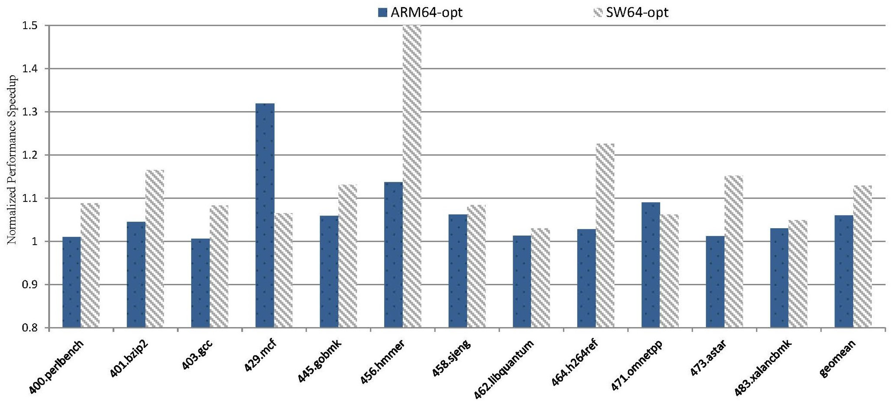
  • We conduct several experiments to evaluate our optimization. The results show a maximum performance speedup of 1.52× on SPEC CINT2006, alongside a reduction in code size of up to 13.98%.
The rest of the paper is organized as follows: Section 2 provides preliminaries about peephole optimization and binary translation. Section 3 outlines our motivation, highlighting potential optimizable code. Section 4 delves into the design details of our optimization for the identified code. Section 5 presents experimental results, evaluating the impact of our optimization. Section 6 introduces related works, and Section 7 concludes the paper.

2. Preliminaries

Binary translation methods mainly include static translation and dynamic translation. In static binary translation, instruction translation is separated from code execution, enabling offline translation with full code optimization, as depicted in Figure 2a. This method demonstrates high execution performance. However, static binary translation faces limitations due to its lack of complete control flow information in advance, encountering challenges related to the issues of self-modifying code, code mining and relocation during runtime, limiting its versatility for large-scale applications. On the other hand, dynamic binary translation adopts a runtime compilation strategy executed simultaneously with translation, and the translation occupies the program’s execution time. When it encounters un-translated code, the context switches to the translator for on-the-fly translation, as shown in Figure 2b. Dynamic binary translation addresses the deficiency of complete control flow information in static binary translation and is widely used. Despite its popularity, the requirements of low overhead and high-quality codes are often in conflict with each other.
No matter whether it is dynamic translation or static translation, binary translation consists of two essential components: program state virtualization and instruction translation. Program state virtualization involves updating the CPU state of the host resources, including registers and memory. Instruction translation involves equivalence transform of the functionality of guest instructions.

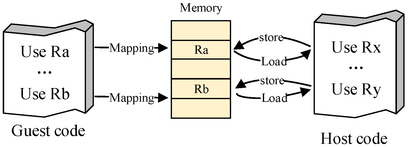
2.1. Program State Virtualization

Program state virtualization dynamically maintains guest resource state in alignment with the instruction execution flow. One challenge in program state virtualization is dealing with register sets between different architectures. In practice, guest registers are mapped to virtual registers within the context of DBT, and these virtual registers are then mapped to specific host memory addresses. The mappings involve numerous intermediate variables. Memory-access overhead, however, is significant.
The introduced intermediate variables encompass temporary, local, and global variables. Optimization becomes feasible through live analysis [14] for temporary and local variables confined within a basic block (BB). However, global variables pose a unique challenge as they persist across all translation blocks throughout the entire simulation. Accessing global variables involves memory access, and defining them requires memory synchronization. Optimizing global variables goes beyond live analysis, requiring special considerations to alleviate the considerable memory-access overhead.

2.2. Instruction Translation

Instruction translation involves a semantic-level equivalent transformation between different ISAs. To formalize this concept, we first introduce the following definition.
Definition 1.
Instruction sequences are semantic-level equivalent if they yield identical output values for a given input and are executed in the same order without branches in the sequence.
Let I be an instruction set and S be a program state, φ I ( I ) denotes the instruction simulation function, and φ S ( S ) denotes the program state virtualization function.
The formalization of the translation from a guest instruction sequence ( I G = < I G 0 , I G 1 , . . . , I Gn > ) and its corresponding state ( S G = < S G 0 , S G 1 , . . . , S Gn > ) to a host instruction sequence ( I H = < I H 0 , I H 1 , . . . , I Hm > ) and its corresponding state ( S H = < S H 0 , S H 1 , . . . , S Hm > ) is denoted as < φ I ( I G 0 ) , φ I ( I G 1 ) , . . . , φ I ( I Gn ) > < I H 0 , I H 1 , . . . , I Hm > , where n represents the number of simulated guest codes, and m represents the number of generated host codes. This translation adheres to Formula (1), ensuring the proper alignment of states throughout the translation process, m i > 0 , n j > 0 .
S Gi = γ ( I G ( i 1 ) , I S ( i 1 ) ) S Hj = φ S ( S Gi )

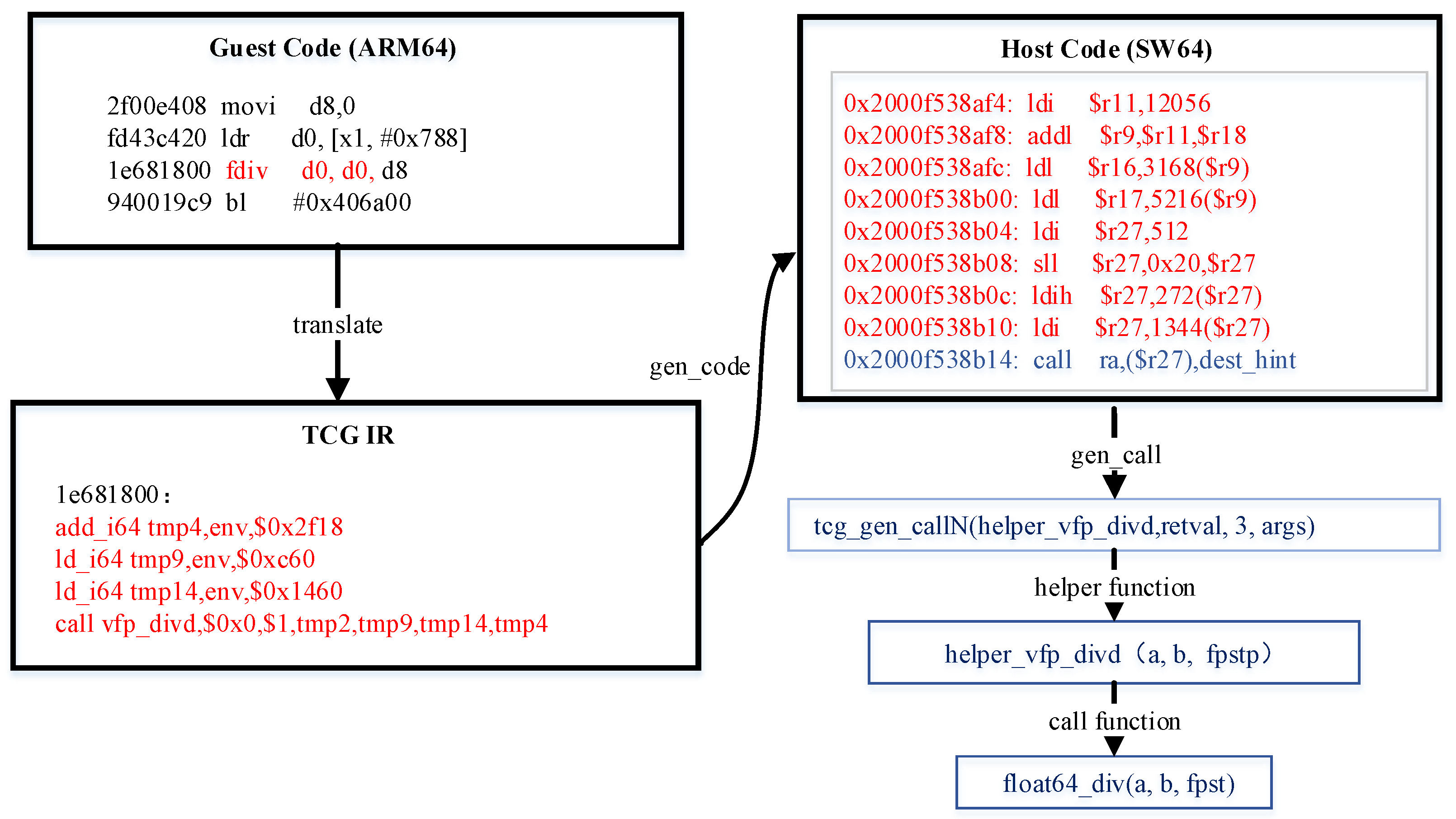
2.2.1. Instruction Emulation

In DBT, achieving a full guest-to-host instruction simulation transition, from I Gi to I Hi , is considered impractical. Instead, adopting the < φ I ( I Gi ) > < I H 0 , . . . , I Hj > approach emerges as a more pragmatic strategy. It is common for a cross DBT system to generate dozens of host instructions when emulating a single somewhat complex guest instruction. IR-based instruction translation is the most commonly used method in DBT. Examples include LLVM IR, TCG IR, VEX IR, etc. The IR serves as a platform-independent code, allowing flexible translation of cross-platform instructions. The instruction emulation unfolds through the sequential translation of guest instructions into the elevation process of IR (designated as G R ), followed by the recompilation and generation of IR (designated as R H ). The formal definitions for these processes are Definitions 2 and 3. The binary lifting process can be symbolized by L to achieve code decoding and encoding.
Definition 2.
Let G R : L ISA R L IR R be the transformation function that lifts guest ISA’ to IR, where G denotes the set of guest instructions and R denotes the set of IR.
The G R is a transformation from platform-dependent to platform-independent. The φ I ( I G ) applies one-step translation in I G at a time.To offset translation overhead, QEMU, for example, refrains from extending the correlation analysis to multiple instructions. The TCG IR (an architecture-independent intermediate representation used by QEMU) solely focuses on interpreting guest instructions individually.
Definition 3.
Let R H : L IR R L H ISA be the transformation function that transforms IR to host ISA", where H denotes the set of host instructions.
The R H is a transformation from platform-independent to platform-dependent. Restricted by the G R stage, there are limited opportunities for extensive analysis and optimization. ISA asymmetry during decoding and encoding incurs considerable memory access. For example, QEMU utilizes virtual registers for storage and retrieval in the translation of register transfer instructions, as depicted in Figure 3. This strategy bridges the gap between distinct ISAs and facilitates the smooth execution of guest programs to the host.

2.2.2. Handling Helper Function

To ease the development, debugging, and maintenance of DBT systems, DBT relies on helper functions to translate guest instructions with complex semantics and functionalities, for example, SIMD, FP, and CPUID instructions. That is, φ I ( I Gi ) exhibits a specific function. For example, as illustrated in Figure 4, the translation from ARM64 fdiv (marked red in Figure 4) to the SW64 platform (an efficient RISC architecture) can be managed through a float64_div helper function (marked blue in Figure 4).
Helper functions bring in the aforementioned benefits for DBT, however, they still face fundamental drawbacks. One is the considerable code size expansion caused by simulating one instruction with a separate function. Another is the considerable amount of additional generated code, which includes function call preparation, handling of passing arguments, and returning of result values. Furthermore, context switches between the code cache and function calls are inevitable, leading to an abysmal performance. We conducted an analysis of QEMU translation using SPEC2006 from x86-64 to SW64, which shows that helper functions lead to a substantial percentage of the execution time, sometimes exceeding 95%.

2.3. Optimization of QEMU

Optimization of TCG: The performance of TCG IR is suboptimal due to its atomic operation-like design. QEMU incorporates register live analysis and store-forwarding optimizations to efficiently release unused registers and eliminate redundant storage access operations. Nevertheless, the lack of optimization for memory-access operations involving global variables results in a significant redundant memory-access overhead in the generated code.
Condition Bit Simulation: Architectures like x86 and ARM64 rely on the EFLAGS registers for condition instructions [15]. In essence, subsequent behavior hinges on the values stored in the EFLAGS register, which contains status flags like overflow (OF), sign flag (SF), zero flag (ZF), auxiliary carry flag (AF), parity flag (PF), and carry flag (CF). However, architectures such as MIPS, RISC-V, and SW64 lack EFLAGS registers. Instead, handling condition instructions’ simulation in these cases involves software-based simulation, requiring the execution of flag register logic functions to update the flag status accordingly. Consequently, substantial memory access and computational overhead are introduced. Li et al. [16] indicated that emulating an ARM condition code instruction costs up to 16 RISC-V instructions on average. To alleviate this overhead, QEMU [14] and Harmonia [17] adopt a lazy computation approach until the results are needed. This strategy effectively reduces redundant evaluations and improves performance. However, Lazy computation involves storing status flag information, which might be unnecessary if not used by subsequent instructions.

2.4. Peephole Optimization

High-quality code generation relies on well-designed instruction selection and register allocation algorithms. One method is to optimize specific parts of the code, which leads to notable improvements in performance and code quality from a local perspective. Peephole optimization [18,19] is a technique that focuses on analyzing code sequences within a sliding window. It aims to find opportunities for making equivalent substitutions, resulting in higher efficiency or a smaller code size. In DBT, this technique can eliminate redundant instructions, reduce unnecessary memory overhead, and simplify specific instruction sequences. Examples include algebraic simplification and specific instruction replacement.

3. Motivation

In this section, we use peephole analysis to identify sequences impacting performance during translation.

3.1. Eliminating Redundant Instructions

Load and store instructions are essential for accessing memory. The load instruction fetches data from memory to registers, while the store instruction moves data from registers to memory. Registers offer significantly faster access compared to traditional DRAM, often tens of times faster or more. Therefore, eliminating redundant memory access can reduce unnecessary memory access.

3.1.1. Redundant Memory Access

Figure 5 provides a translation example of x86-64 ‘pushq’ to ARM64. The corresponding TCG IR for ‘pushq’ is shown in Figure 5a, and the translated ARM64 code is shown in Figure 5b. The x19, x20, and x21 represent different types of registers, and [x19,#0x20] indicates the memory address corresponding to x19 + 0x20. When two ‘pushq’ instructions are translated, they both write the values of registers x20 and x21 into the same address [x19 + 0x20]. However, since the value of x19 remains constant, both ‘pushq %rax’ and ‘pushq %rsp’ are executed directly at the address [x19 + 0x20]. As a result, the former ‘str x20, [x19 + 0x20]’ is overwritten by ‘str x21, [x19 + 0x20],’ leading to write-after-write redundant memory access. Therefore, ‘str x20, [x19 + 0x20]’ is a redundant operation.
In a broader context, the ‘rsp’ value is synchronized with memory whenever it is defined, as are other similar directives such as ‘popq’ and other stack operations. Ideally, the ‘rsp’ should only be written back to memory during the final update. Our study of memory synchronization in the SPEC2006 [20] suite reveals an average of 2.1 global variable memory storage occurring in a BB. Accordingly, reducing unnecessary memory synchronization can significantly decrease memory access.

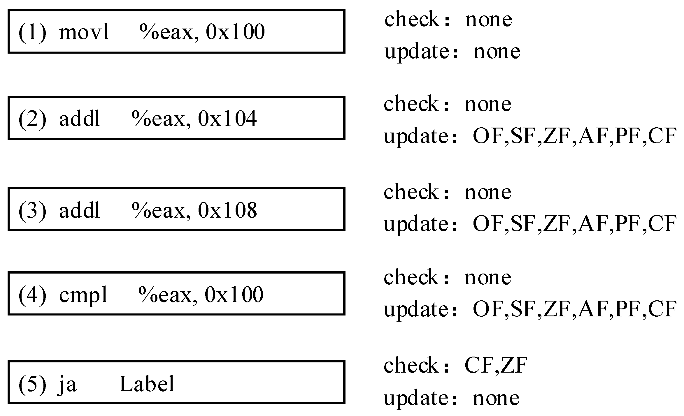
3.1.2. Unused Status Flag Storage

Status flag used by condition instructions can be categorized into read-only (check), write-only (update), or read-and-write (check and update). Read corresponds to a load process, while write corresponds to a store process.
In a BB, the status of condition bits is determined by whether subsequent instructions utilize them. If utilized, it is active; otherwise, it is inactive. Importantly, not all instructions utilizing the status are considered active. Consider the following x86-64 assembler code:
(1)
movl %eax, 0x100
(2)
addl %eax, 0x104
(3)
addl %eax, 0x108
(4)
cmpl %eax, 0x100
(5)
ja Label
The update and check for each status flag in the provided assembler code are drawn as Figure 6. The ‘movl’ instruction in (1) does not modify any status flags. Sequentially, both ‘addl’ instructions in (2) and (3) update the OF, SF, ZF, AF, PF, and CF. Similarly, the ‘cmpl’ instruction in (4) updates these flags. The ‘ja’ instruction in (5) checks the CF and ZF flags affected by (4), determining the program’s next state. Notably, the status flags modified by (2) and (3) are overwritten by (4), and a store-after-store memory occurs. Ideally, only the required status flags updated by (4) are needed.

3.2. Simplifying Suboptimal Instruction Sequence

During cross-ISA translation, it is common to employ multiple host instructions to simulate a single guest instruction, as depicted in < φ I ( I G 0 ) , φ I ( I G 1 ) , . . . , φ I ( I Gn ) > < I H 0 , I H 1 , . . . , I Hm > . When simulating instruction sequences, various mapping methods can theoretically be applied, resulting in multi-versioned host instruction sequences. One straightforward solution to this issue is to explore a more effective translation method.

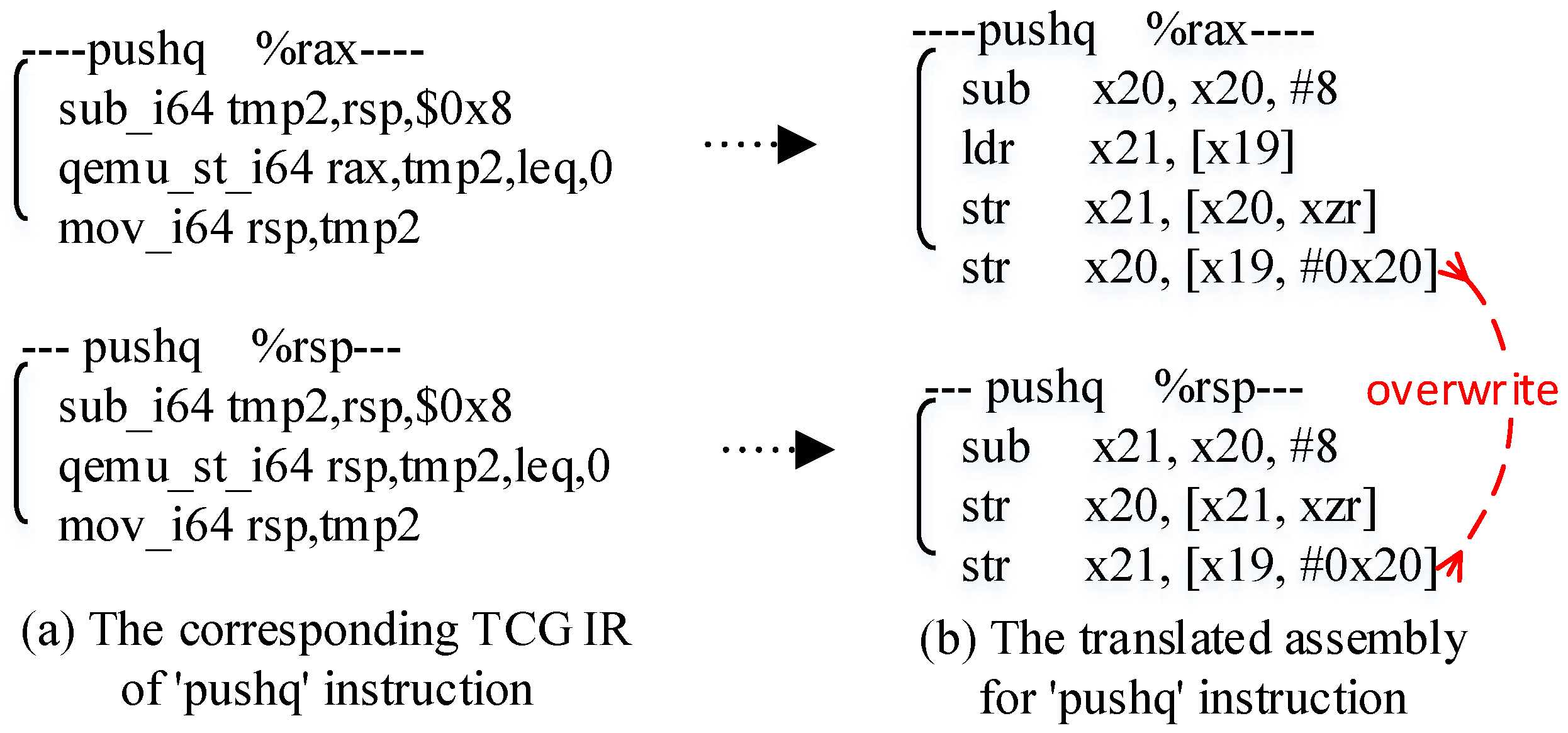
3.2.1. Suboptimal Instruction Simplification

Definition 4.
A specific translated instruction sequence in a BB is considered suboptimal if there exists a superior version that can minimize the execution overhead.
For instance, the p x o r x86-64 instruction, which performs a bitwise logical XOR operation on two input operands, is simulated by QEMU through a p x o r _ x m m helper function. However, when the p x o r instruction has identical input parameters, it is essentially equivalent to directly writing zero into the output.
We observe that p x o r and v p x o r instructions with identical input parameters are prevalent in SPEC2006, constituting over 98% of cases. Leveraging this insight, by writing ‘0’, the target register can effectively enhance the running efficiency while eliminating helper function calls.

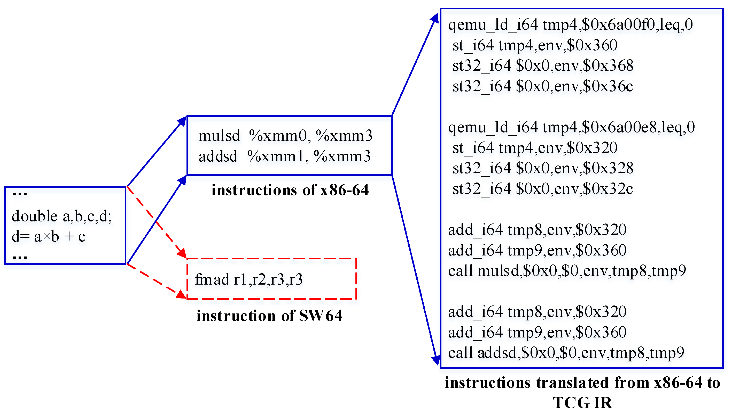
3.2.2. Specific Code Replacement

In general, ISA-specific instructions designed for various purposes, such as data prefetching, vector operations, and floating-point acceleration, can significantly enhance computational power. Consider the expression d = a b + c , where a, b, c, and d are all double-precision floating-point variables.
By default, x86’s gcc compiler (O2) does not generate a scalar floating-point multiply–add instruction for this expression. It resorts to ‘mulsd’ and ‘addsd’ instructions. In contrast, SW64 and ARM64 support more optimized ‘fmad’ (multiply–add) instruction, combining ‘mulsd’ and ‘addsd’ into a single instruction. During x86-to-SW64 and x86-to-ARM64 translation, the original guest semantics are maintained, simulating ‘mulsd’ and ‘addsd’ separately. This results in extensive computational and memory-access operations, as depicted in Figure 7. As a result, the instruction simulation by DBT is less competitive than that of native compilers.

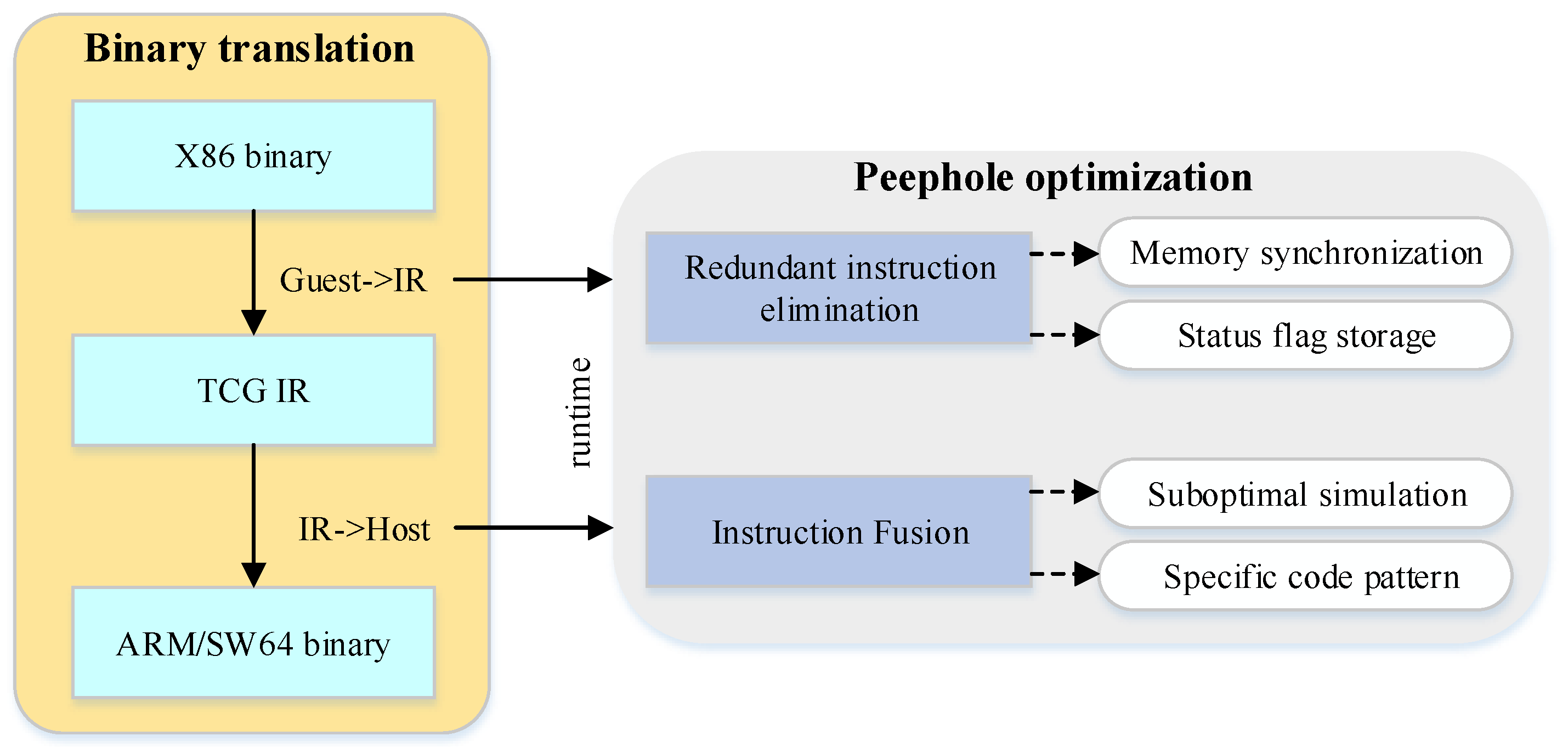
4. Performance Optimization via Peephole Optimization

4.1. Methodology Overview

To address the performance issues stemming from significant memory-access overhead and underutilization of host architecture features, we propose integrating peephole optimization into DBT. Figure 8 provides an overview of our methodology.
To tackle the challenges of redundant memory synchronization for global variables and the unnecessary storage of status flag values, we propose a redundant instruction elimination optimization approach using live variable analysis. Additionally, to address the challenge of incongruent semantic gaps between the guest and host ISAs, we investigate an instruction fusion approach within a specific peephole window, which can be the entire basic block or a subset.

4.2. Optimization for Consecutive Memory Access

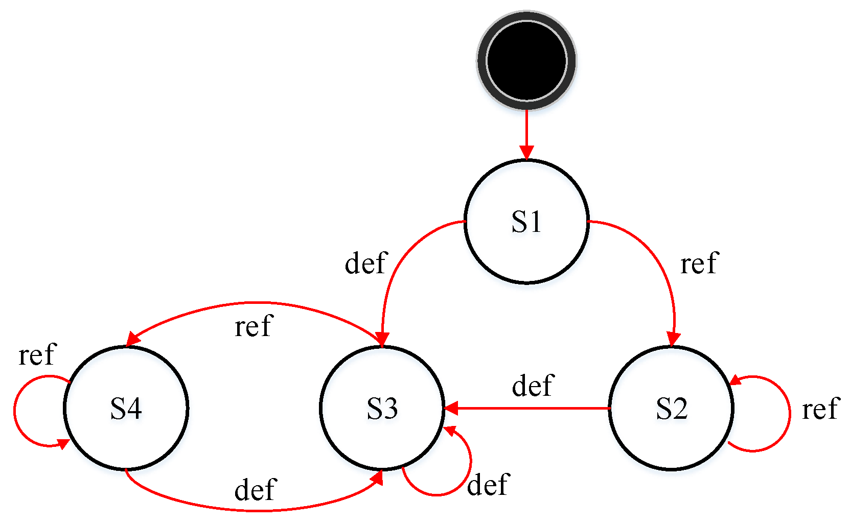
4.2.1. Formalizing Consecutive Memory Access

In theory, redundant consecutive memory-access instructions manifest in the following four scenarios:
(1) Redundant store–load: If there is no re-definition to the same register ‘reg’ between the store and load access, the latter load is redundant.
(2) Redundant store–store: If the value of the registers ‘reg’ undergoes the same memory write through a repetitive store access, and there are no other instructions referencing the memory during the store–store couple, the former store access is redundant.
(3) Redundant load–load: If there is no re-definition to the same register ‘reg’ between the load–load couple, the latter load is redundant.
(4) Redundant load–store: If there is no re-definition to the same register after the load access, the latter store access is redundant.
We formalize the four identified scenarios of redundant memory access as follows:
S t o r e 1 ( M , r ) L o a d 1 ( M , r ) S t o r e 1 ( M , r ) ( S A L )
S t o r e 1 ( M , r ) S t o r e 2 ( M , r ) S t o r e 2 ( M , r ) ( S A S )
L o a d 1 ( M , r ) L o a d 2 ( M , r ) L o a d 1 ( M , r ) ( L A L )
L o a d 1 ( M , r ) S t o r e 1 ( M , r ) L o a d 1 ( M , r ) ( L A S )
In the formalized context, S t o r e ( M , r ) denotes writing the value of the register, named r, to the memory address, named M, and L o a d ( M , r ) indicates loading the value from M to r. Consequently, the store–load operation can be simplified into a single store instruction, denoted as S A L . Similarly, the optimization for store–store is denoted as S A S , load–load optimization is denoted as L A L , and load–store optimization is represented as L A S .

4.2.2. Live Variable Analysis in DBT

Live variable analysis (LVA) determines the relationship between variable definitions and references to determine the exposed active set of variables. Any variables unused within this set are identified as dead code and can be safely removed. We apply LVA to DBT by examining variable definitions and references in each block through a reverse linear scan. Instructions whose output variables are inactive are marked as redundant instructions.
For clarification, we give the following definition first.
Definition 5.
d e f [ I ] , set of variables defined by instruction I.
Definition 6.
r e f [ I ] , set of variables referred by instruction I.
In a BB, d e f [ I ] and r e f [ I ] are determinable through computation from the control flow graph, establishing them as recognized variables.
Definition 7.
Suppose T is a referenced variable at the program point p. If T is live before p and not defined at p, then T is also live at the position of p, and is marked as live. Otherwise, it is marked as #live.
The liveness of instruction variables exhibits transitivity. Assuming the instruction corresponding to program point p is I, if variable T is live before point p and remains undefined at point p, then T continues to be live after point p.
If a BB references a value to variable T and does not recalculate it afterwards within the same block, we say that the BB has killed T. Conversely, if the BB references a variable and does not reassign a value to T later, we say the basic block BB has activated T. Consequently, the expression transfer function f BB ( T ) can be represented by Formula (2).
f BB ( T ) = ( T d e f BB ) r e f BB
When analyzing liveness for each instruction I in a BB, the current instruction’s liveness relies on its own status and the set of live variables from the preceding instructions (Formula (3)). Here, s u c c ( I ) represents the subsequent instruction of I.
l i v e ( I ) = ( n succ ( I ) l i v e ( n ) d e f ( I ) ) r e f ( I )
To identify the redundant instruction I, we examine whether the defining variable, denoted as d e f [ I ] , is not live in its successor instructions (i.e., not in j = I + 1 n l i v e ( j ) ). If it is met, it is a redundant definition, as outlined in Formula (4).
d e f [ I ] j = I + 1 n l i v e ( j ) =
Challenge: While Formula (4) is effective in identifying and eliminating redundancies defined by operations within BBs, integrating it into DBT optimization, such as QEMU, presents challenges. DBT relies on memory access for simulating global variables, including cross-procedure registers, stack registers, and variables introduced during translation. Notably, these global variables are mapped to fixed memory addresses by DBT. Updating these global variables is managed through memory sync-restore, involving two mappings: the source platform’s global variable information (GV) to the virtual register, and the virtual register (vMEM) to the host storage unit. The mapping process is illustrated in Figure 9.
In Figure 9, temp temporarily holds guest register values. However, when leaving the block, its updated value is lost as temp is released. To ensure accuracy, we promptly sync the updated global variable with memory after any value-defined operation in the block, marked as “SYNC” in Figure 9.
QEMU utilizes a real-time memory write-back approach. Upon writing a global variable in the BB, a memory synchronization is promptly generated. As mentioned before, applying Formula (4) for optimizing global variables with redundant instructions is utopian, as it might incorrectly identify variable synchronization to memory operations as redundant instructions.

4.2.3. Eliminating Redundant Memory Access Based on LVA

To ensure global variables synchronize to memory appropriately, we add a ‘sync’ attribute to all of them by default. When a fixed variable carries this attribute, it requires a memory write-back. Accordingly, excessive and redundant memory write-backs are employed. In Figure 9, both ‘insti’ and ‘instk’ perform fixed value operations on ‘Temp’, causing duplicate SYNC operations, like store-load, store-store, and store-load.
Initially, all global variables in the BB undergoing define operations are marked with the ‘sync’ attribute. During reverse analysis, if we encounter a defining operation of a global variable with the ‘sync’ attribute, we change it to ‘#sync’. For operations referencing variables, the ‘sync’ attribute remains unchanged. The reverse analysis guarantees memory synchronization when the variable is last defined. If the fixed value of this global variable is encountered elsewhere, we change the attribute to ‘#sync’, indicating that memory synchronization is no longer necessary at the current position.
To achieve this, we propose a detailed state diagram for variable live transformation, as illustrated in Figure 10. S1 represents the ‘ # l i v e | s y n c ’ state, S2 corresponds to the ‘ l i v e | s y n c ’ state, S3 corresponds to the ‘ # l i v e | # s y n c ’ state, and S4 indicates the ‘ l i v e | # s y n c ’ state.
For correctness purposes, if an instruction’s defined variable anastomoses ‘ # l i v e | # s y n c ’ state, it indicates that the instruction is deemed redundant in terms of synchronization. In other words, the instruction is redundant, as in Formula (5):
s y n c d e f [ I ] j = I + 1 n l i v e ( j ) =
Algorithm 1 shows our redundant instruction elimination based on live variable analysis (RIE-LVA) algorithm. We perform a bottom-up analysis of each instruction, utilizing the live state diagram in Figure 10, and determine the live, dead, and sync attributes of the variables. After this step, we can identify the global variable T with the ‘ # l i v e | # s y n c ’ attribute and mark the corresponding memory-access instructions as redundant.
Algorithm 1 RIE-LVA algorithm.
Electronics 13 01608 i001

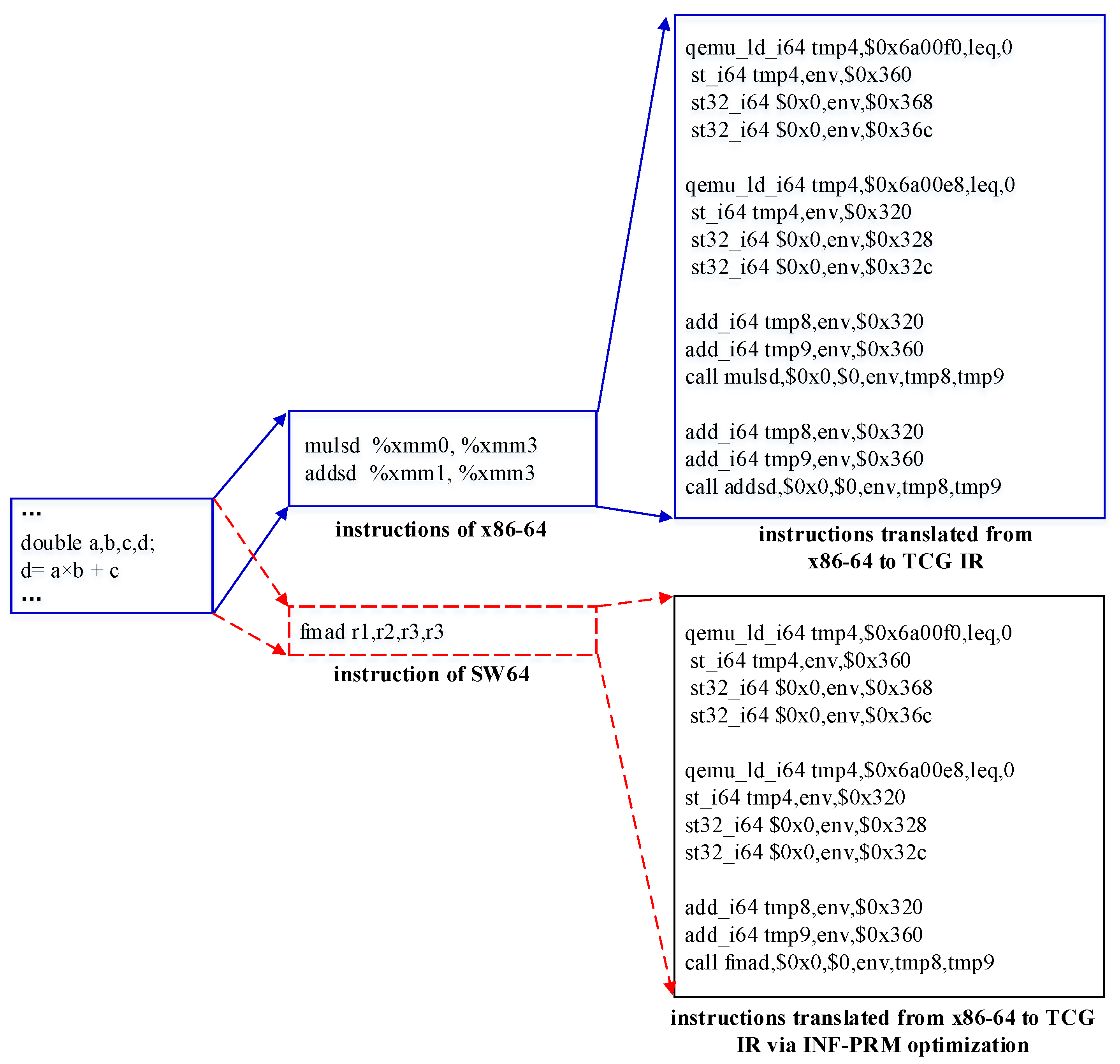
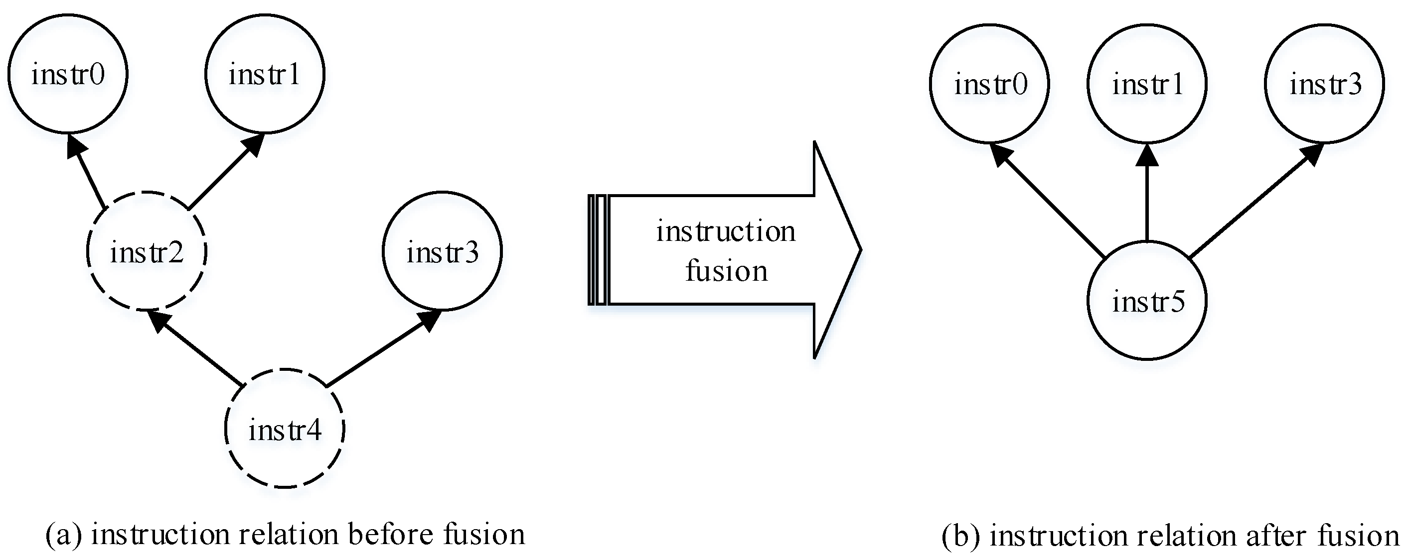
4.3. Instruction Fusion Optimization

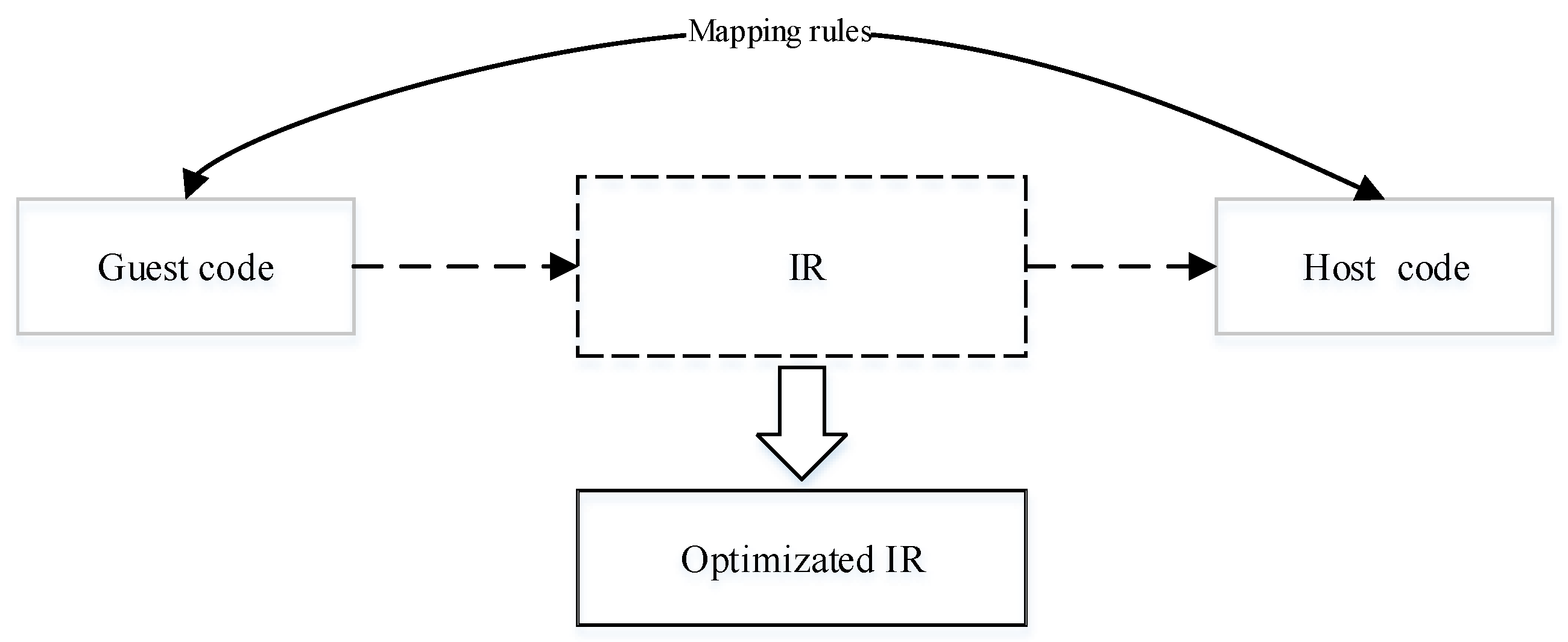
4.3.1. Instruction Semantic-Level Transformation Model

First, we model the instruction transformations as follows: let [ g u e s t ] ISA represent the guest ISA function sets, [ h o s t ] ISA represent the host ISA function sets, and χ ( I ) be the functionality of an instruction. Given the x86-64 ‘addq’ and SW64 ‘addl’ instructions, where both χ ( a d d q ) and χ ( a d d l ) denote a 64-bit integer addition, we treat x86-64 and SW64 as semantically equivalent when performing 64-bit integer additions. We then further formalize these transformations in the following manner:
  • Case 1: χ ( I ) [ g u e s t ] ISA and χ ( I ) [ h o s t ] ISA . Both the guest ISA and host ISA encompass the functionality of instruction I.
  • Case 2: χ ( I ) [ g u e s t ] ISA and χ ( I ) [ h o s t ] ISA . The guest ISA set encompasses the functionality of instruction I, but the host does not.
  • Case 3: χ ( I ) [ g u e s t ] ISA and χ ( I ) [ h o s t ] ISA . The host ISA set encompasses the functionality of instruction I, but the guest does not.
Facing < φ I ( I G 0 ) , φ I ( I G 1 ) , . . . , φ I ( I Gn ) > < I H 0 , I H 1 , . . . , I Hm > translation, for Case 1, the transformation from I G to I H is straightforward, and the code size is precisely n m . For Case 2, multiple instances of I H simulate the transformation of a single I G . This involves helper functions, resulting in a code size of n m , despite the significant expansion. Case 3 aims to generate a better-quality host I H compared to I G , in theory, n m . However, in practice, guests I G and S G impose restrictions on transformations, creating challenges to the efficient extension of host-specific instructions. Instead, the less-efficient simulation method is adopted, similarly to Case 2.
Next, we apply the instruction fusion peephole optimization to the specific instruction sequence outlined in Case 3.

4.3.2. Analyzing Data Dependency

Instruction fusion combines various instructions into more efficient nodes, reducing overhead associated with instructions, registers, clock cycles, and memory access. More specifically, Figure 11 depicts the instruction fusion process, where circles represent instructions, the virtual circle indicates the instruction for merging, and arrows denote data dependencies between instructions.
In Figure 11a, instr2 depends on the outcomes of inst0 and inst1, and instr4 relies on instr2 and instr3. Through fusion optimization in Figure 11b, instr2 and instr4 are combined into instr5, maintaining the data dependency between instr2 and instr4. This fusion shortens the data dependency chain from 2 to 1, streamlining the instruction sequence and reducing associated dependencies.
Though the idea of instruction fusion is fairly intuitive, it is quite challenging to put it into practice due to two reasons: (1) exploring data dependencies within the basic block is complex, and (2) identifying fusible instruction sequences from [ g u e s t ] ISA to [ h o s t ] ISA is challenging. First, let us explore data dependencies.
Definition 8.
The output variable of statement S is denoted as O U T ( S ) .
Definition 9.
The input variable of statement S is denoted as I N ( S ) .
Definition 10.
Data dependencies stem from interactions with the same data through reading/writing or computing/using. For statements S and T, if variable x satisfies the following conditions, we denote T as dependent on S, written as S δ T ; otherwise, there is no dependency between them.
Flow dependency: For variables x, x O U T ( S ) , and x I N ( S ) , if there is a path from statement S to statement T and T utilizes the value of x computed by S, then T exhibits stream dependence on S and is marked as S δ f T .
Anti-dependency: For variables x, x O U T ( S ) , and x I N ( S ) , if there is a path from statement S to statement T but S uses the value of x before T assigns a value to x , then T is anti-dependent on S and is marked as S δ a T .
Output dependency: For variables x, x O U T ( S ) , and x O U T ( S ) , if statement S assigns a value to variable x before statement T also writes x, there is a path from S to T, so then T is output-dependent on S and is marked as S δ o T .
Dependency solving: In the statement S i , S pre denotes the precursor statement of S i and S succ denotes the successor statement of S i . If the specified conditions are fulfilled, S i δ f S pre , that is, O U T ( S i ) I N ( S pre ) . S i δ a S succ , that is, I N ( S i ) O U T ( S succ ) , indicating a dependency relationship either between S i and S pre or between S i and S succ ; otherwise, no dependency relationship is maintained. Notably, S i and S pre , as same as S succ and S i no need be contiguous, a strict order between them is sufficient. Thus, in the following sections, we will discuss the application of instruction fusion to DBT based on the dependency relationships between the candidates.

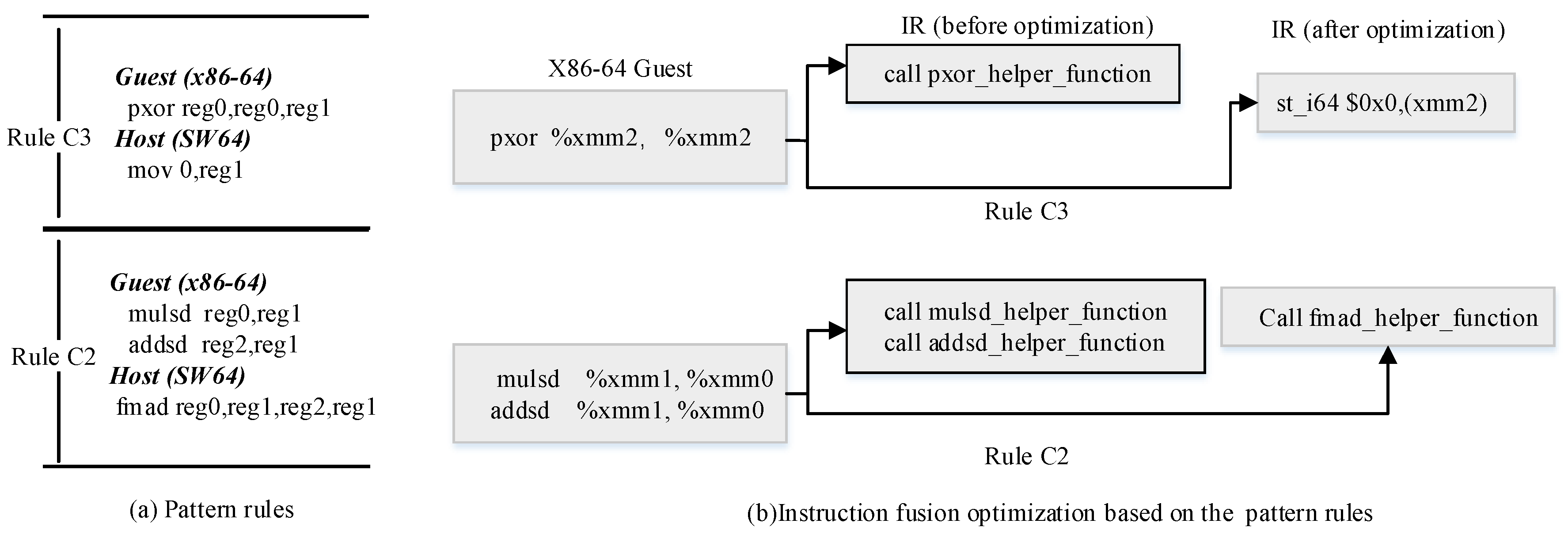
4.3.3. Instruction Fusion Optimization Based on Pattern-Matching

As mentioned before, instruction fusion involves analyzing candidate instruction sequences and applying equivalence transformations to optimize code. There are two methods commonly investigated: (1) The directed acyclic graph (DAG) construction method, which relies on intact data flow and is challenging to obtain in DBT due to the lack of preserved data flow relationships across BBs. (2) The pattern-matching method, which involves template-matching based on predefined pattern rules during the instruction selection stage, independent of data flow. In this paper, we adopt the pattern-matching method for instruction fusion, called INF-PRM (Instruction Fusion based on Pattern Rule Matching)
To create pattern mapping, we first build a rule base. Following the method in reference [21], we establish instruction mapping rules between x86-64 and SW64 as well as x86-64 and ARM64. Considering the substantial overhead, we emphasize the translation of integer, floating-point, and logical operation instructions, given the poor quality of the generated code.
Using instruction mapping rules, optimizations can be applied to generate optimized IR, aligning with the existing DBT. This optimized IR aims to produce characteristic instructions that are more consistent with the host ISA. As depicted in Figure 12, during the lifting process of G R : L ISA R L IR R and R H : L IR R L H ISA " , the corresponding optimized IR is generated using the established mapping rules. Subsequently, the host instruction is generated based on this optimized IR.
This approach eliminates the need to delve into register-mapping intricacies as long as the required data dependency relationships are maintained. The following are three concrete examples of pattern-matching rules:
Rule C1: Fusion of single-precision FP multiply–add/sub operations into compound single-precision FP multiply–add/sub instructions.
Rule C2: Fusion of double-precision FP multiply–add/sub operations into compound double-precision FP multiply–add/sub instructions.
Rule C3: Fusing logical operations involves performing an XOR operation with the same source and destination operands, resulting in writing zero to the destination.
As illustrated in Figure 13, we provide an example of our instruction fusion optimization based on pattern-matching. We first formulate the matching rules. Throughout the translation of instructions, we implement the mapping from guest to host for instructions that satisfy dependency relationships. After optimizing, the ‘pxor’ instruction transitions from invoking a helper function to a straightforward TCG assignment operation, as depicted in Figure 13b. Simultaneously, the double-precision FP multiply and add instructions, following fusion, are efficiently translated into a single helper function that implements the fused FP multiply–add.
Instruction fusion optimization can be implemented at different stages of DBT: (1) Guest-to-IR stage: Fusion is performed while parsing the guest binary code snippet. Specific instructions are directly merged based on the instruction context within the BB. For example, the optimization shown in Figure 7. (2) IR-based stage: This stage involves analyzing the internal data flow dependencies of BBs using IR. Optimizations, such as the ‘pxor’ simplification mentioned in Section 3.1.2, can be applied at this stage. (3) IR-to-host stage: In this stage, instruction fusion is applied during the conversion of the IR operation into host code, involving the use of specific host instructions.

5. Experimental Results

5.1. Experimental Setup

Testbed. We take SW64 [3] and ARM64 [22] as the host ISA and x86-64 [23] as the guest ISA.
  • SW64 host: The host machine has 2.40 GHZ and SW3231 processors for a total of 32 cores. The machine is equipped with 512 GB of RAM, 32 KB of L1 cache, 512 KB of L2 cache, and 64 MB of shared L3 cache and runs UOS V20 with Linux kernel v4.19.0.
  • ARM64 host: The host machine has 2.1 GHZ and Phytium S2500 processors for a total of 64 cores. The machine is equipped with 2 MB of L2 cache and 64 MB of shared L3 cache and runs Kylin Linux kernel v4.19.0.
Benchmark. We take SPEC2006 [20], Nbench BYTEmark [24], and Stream [25] as benchmarks. SPEC2006 is an industry-standardized test suite that comprises two test sets, CINT2006 and CFP2006. It provides a comprehensive set of tests for evaluating binary translation systems, enabling an effective analysis of DBT’s translation efficiency. We conduct our SPEC2006 experiments with single-threaded execution.
Nbench, short for native mode benchmark and later known as BYTEmark, is a synthetic computing benchmark program intended to measure a computer’s CPU, FPU, and memory system speed. Nbench is single-threaded.
In addition, we utilized the Stream benchmark [25] to evaluate the impact of our optimizations on multi-threaded execution. Notably, SW3231 and S2500 support a maximum of 32 and 64 threads, respectively. To maintain a consistent comparison of key indicators, we conduct the experiments with the thread count set to a maximum of 32.
Methodology. We use performance speedup to measure the optimization effects on the translated code compared to the runtime before optimization. The reduction in code size serves as a measure to assess the extent of code optimization, which can be calculated using the formula ( B A ) / B , B is the code size before optimization and A is the code size after our optimization. The benchmark defaults with reference input. To minimize the effect of measurement noise, we repeat each test three times and report an average result.
All source codes are compiled with GCC v8.3.0 -O2. The baseline is derived from the latest QEMU v6.0 [14]. As the open-source QEMU does not support SW64 architecture, we modify the backend of QEMU to support SW64 before conducting our optimizations.
Baselines. We compare three versions of translators:
  • QEMU base version: Compiles the QEMU v6.0 using GCC on both ARM64 and SW64 platforms, employing the default configuration settings.
  • ARM64-opt version: Combines ARM64 with the QEMU base version, incorporating RIE-LVA and INF-PRM optimizations.
  • SW64-opt version: Combines SW64 with the QEMU base version, incorporating RIE-LVA and INF-PRM optimizations.

5.2. Overall Impact on Performance

Before comparing overall performance, we conducted tests on the translation efficiency of the QEMU base version. We employed the SW64-base for x86-to-SW64 translation, achieving an average translation efficiency of 25.08% for CINT2006 and a translation efficiency of 7.29% for CFP2006. For the x86-to-ARM64 base version, there was an average translation efficiency result of 24.14% for CINT2006 and a efficiency of 8.24% for CFP2006. These results indicate that our SW64 base version matches ARM64 base version in translation efficiency.
To evaluate the performance speedup achieved by our optimization proposed in this paper, SPEC2006 and Nbench tests were conducted using the following versions: ARM64-opt and SW64-opt.
The normalized speedup results for CINT2006 are illustrated in Figure 14. In SW64 architecture, 456.hmmer achieves a maximum speedup of 1.52×, with an average speedup of 1.13×. Similarly, in ARM64 architecture, 429.mcf achieves a maximum speedup of 1.32× and an average speedup of 1.07×.
Figure 15 shows the normalized speedup achieved by our optimization on CFP2006 suite. In SW64, 482.sphinx3 exhibits a maximum speedup of 1.09×, with an average speedup of 1.03×. On the other hand, for ARM64, 416.gamess showcases a speedup of 1.11×, with an average speedup of 1.05×.
Figure 16 shows the normalized speedup achieved by our optimization on Nbench suite. In SW64 architecture, BITFIELD exhibits a maximum speedup of 1.64×, with an average speedup of 1.16×. On the other hand, for ARM64 architecture, BITFIELD showcases a speedup of 1.19×, with an average speedup of 1.08×. Interestingly, BITFIELD is sensitive to our optimization, this is because the hotspot of BITFIELD primarily involves extracting memory data, performing calculations, and then writing the result back to the original location. In QEMU, both arithmetic and logic operations require significant status flag storage. Our optimization proposed in this paper effectively amortizes the memory storage overhead.

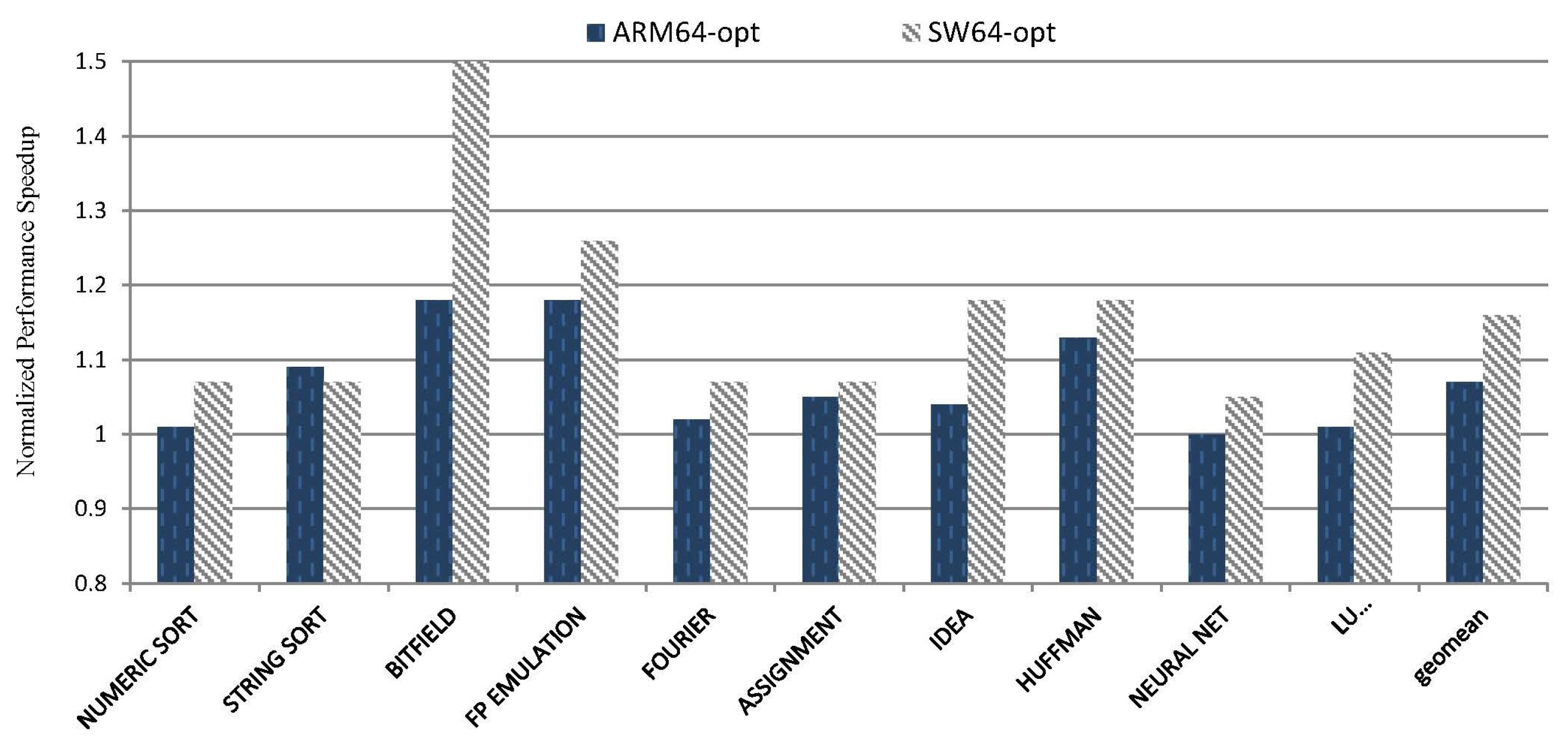
5.2.1. RIE-LVA Performance

Figure 17 shows the impact of the RIE-LVA optimization on CINT2006 benchmarks. For SW64, our approach achieves the maximum speedup of 1.48× (456.hmmer), while an average of 1.09×. Similarly, on ARM64 architecture, our approach achieves the maximum speedup of 1.28× (429.mcf), with an average of 1.05×. The RIE-LVA optimization demonstrates effectiveness on CFP2006 benchmarks, with a speedup ranging from 0.98× to 1.08× on SW64 and ARM64. This indicates that the optimization has a noticeable impact on integer benchmarks, while not significantly affecting FP benchmarks.
The limited effectiveness of RIE-LVA on FP benchmarks can be attributed to its primary focus on live analysis and the optimization of IR. This optimization does not extend its analysis to redundant instructions within helper functions, unfortunately, FP translation relies heavily on helper functions.
An interesting observation arises when comparing the impact on specific benchmarks. For example, the 456.hmmer benchmark for SW64 experiences a significant acceleration effect, while the 403.gcc benchmark does not. Further analysis of the hotspot blocks in the 456.hmmer reveals that a substantial portion (59.2%) of instructions involve operations between memory and general access, such as ‘mov’ and ‘adds’. As a result, this benchmark entails a large number of memory-access instructions. In contrast, the hotspot block in the 403.gcc benchmark involves relatively fewer memory access events.

5.2.2. INF-PRM Performance

Figure 18 presents the impact of INF-PRM optimization on the CFP2006 benchmarks for both SW64 and ARM64. For SW64, the maximum speedup achieved is 1.08× (453.povray), with an average speedup of 1.04×. Similarly, for ARM64, the maximum speedup reaches 1.11× (416.gamess), with an average speedup of 1.03×.
We find the results demonstrate a direct correlation between pattern-matching success rates and optimization effectiveness. A higher success rate corresponds to greater performance improvements. For SW64, the 444.namd benchmark exhibits 2708 occurrences of FP multiplication and addition combination, while the 454.calculix benchmark shows only 373 occurrences. This discrepancy explains why the optimization effect on SW64 is significant for 444.namd but less pronounced for 454.calculix. Similarly, on the ARM64 platform, the optimization impact is prominent for 416.gamess but not for 410.bwaves.

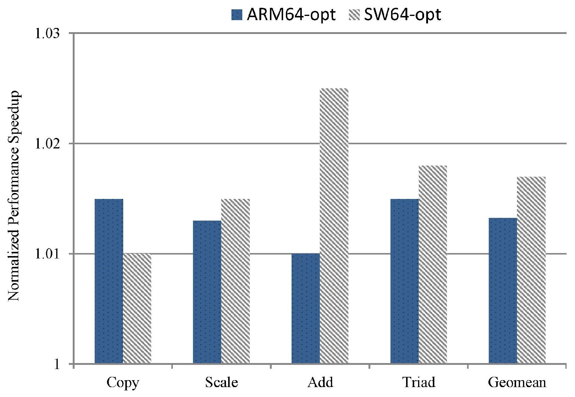
5.2.3. Multi-Thread Suite Performance

We evaluate our proposed techniques using Stream with multiple threads. Specifically, we configured the number of threads to 32 and executed the binary code generated from DBT. The acceleration effect is summarized in Figure 19, showing a speedup ranging between 1.0× and 1.02×. This indicates that our optimization is applicable to multi-threaded applications.

5.2.4. Translation Overhead Impact

We next study the translation overhead caused by our approach. The results indicate that the RIE-LVA optimization incurs a translation overhead of less than 0.5%, which is negligible. On the other hand, the INF-PRM optimization introduces overhead typically ranging from 0.1% to 3%; the overhead can be attributed to its reliance on pattern-matching and data dependency analysis. In cases where instruction replacements are infrequent, the additional overhead from these checks may amortize the benefit from the performance gains obtained through optimization. This phenomenon explains the observed negative acceleration effects in the 454.calculix and 410.bwaves tests.

5.3. Overall Impact on Code Size

Finally, we study the impact of our approach on code sizes. Figure 20 shows the code size reduction on SPEC2006.
As the data show, when all optimizations are applied, for CINT2006 on SW64, the code size reduction ranges from 1.65% to 12.04%, with an average of 5.35%. For CFP2006 tests, the reduction ranges from 0.31% to 13.74%, with an average of 2.64%. On ARM64, the reduction for CINT2006 ranges from 1.63% to 9.25%, with an average of 4.71%. For CFP2006 tests, the reduction ranges from 0.14% to 13.98%, with an average of 2.36%.
To better understand the effect of our approach impact on code size, we evaluate a concrete example referred in Section 3.2.1. The corresponding TCG IR in Figure 21a shows that (2e), (3d), and (4c) define cc_dst, which belongs to S A S redundant memory access. The last definition of cc_dst is at (4c). After applying the RIE-LVA optimization, both (2e) and (3d) can be eliminated, leading to the optimization effect displayed in Figure 21b. As a result, the size of IR decreases from 13 to 11.
Additionally, the INF-PRM optimization targets specific conditions, like FP multiplication and addition, FP multiplication and subtraction, FP negative multiplication and subtraction, and ‘pxor’ return to zero sequences, aiming to reduce the frequency of calls to helper functions and produce concise host-translated code. For example, DBT simulates ‘mulsd’ and ‘addsd’ by utilizing helper functions, as depicted in Figure 22. The INF-PRM optimization merges ‘mulsd’ and ‘addsd’ instructions into ‘fmad’. This optimization not only streamlines the code but also eliminates an extra helper function call.

5.4. Discussion and Limitations

5.4.1. Limitations

This paper focuses on DBT performance, primarily targeting user-level translation. However, this is not suitable for system-level translation. This is due to the requirements of maintaining virtual-to-physical address coordination and real-time CPU state synchronization in system-level translation. Our optimization may lead to belated memory state synchronization in system-level issues. Additionally, our optimization aims to address instruction quality issues from x86 to RISC architectures translation. While our approach can guarantee correctness for RISC platform guests, its optimization benefit may be limited. Furthermore, our implementation relies on QEMU and has not been verified for other frameworks. It will be interesting to see how our work benefits other DBTs in the future.

5.4.2. Benefiting Other Applications

Our optimizations are architecture-independent and significantly enhance QEMU-based binary translation. We have confirmed this acceleration in SPEC2006, Nbench, and Stream benchmarks. They are equally effective for user-level translations such as PDF and Oracle. Additionally, they are valuable in dynamic instrumentation analysis, software migration, and program behavior analysis based on DBT.

6. Related Work

Peephole optimization is widely used in binary translation optimization [21,26,27,28,29]. Bansal et al. [21] utilized peephole optimization in rule-based binary translation. They employed a specific window size for peephole analysis and a superoptimization approach to automatically discover optimal translation rules. This facilitated end-to-end mapping between PowerPC and x86. However, this approach involves an almost brute-force rule learning, which has a substantial initial cost. Tan et al. [26] utilized a specific data dependency graph to combine live analysis and peephole optimization, effectively eliminating redundant instructions in generated code of a static binary translator. Experimental results on the benchmark programs from the SPEC2006 benchmark suite show that an average 1.17× performance speedup can be achieved. Similarly, Sun et al. [27] conducted peephole optimization on a static binary translator to eliminate redundant instructions. Rocha et al. [28] integrated peephole optimization to optimize redundant memory access and fence instructions during the translation of concurrent programs. However, the above approaches primarily face static binary translation, where the impact of peephole optimization’s overhead is not a significant concern, whereas our paper is implemented in a dynamic binary translation. As a matter of fact, our optimization incurs minimal translation overhead, consistently measuring less than 3% in experiments.
Instruction fusion has been commonly applied in processor co-design, aiming to enhance instruction field utilization and code density [30,31]. Celio et al. [32] employed macro-op fusion to accelerate idioms created by legacy ISA decisions, altering the ISA shape to match internal macro-ops and facilitating the addition of new ISAs. Singh et al. [33] focused on instruction fusion, exploring opportunities for fusing additional instructions in a high-performance general purpose pipeline. Lupon et al. [34] used DBT with slight modifications to an FMA unit, and achieved the fusion of FP multiply and FP add to produce an FP multiply–add instruction. However, these co-design methods primarily require synchronous modifications. In an attempt to improve the quality of host-side code, Jiang et al. [35] proposed a parameterized translation rule learning method for instruction generation. While this method demonstrates high translation efficiency, its flexibility is relatively constrained. In contrast, this paper uses the existing framework of binary translation, which creates its own patterns during instruction translation and subsequently maps these patterns to generate efficient instructions that adhere to the target architecture.
The current binary translation for condition bit simulation mostly involves the lazy computation approach to reduce the condition bit computation. However, this method increases the memory-access consumption during execution. To tackle this problem, Wang et al. [36] proposed a pattern-based translation method for status flags. They selected instruction combinations with equivalent semantics on the target, thereby reducing the translation workload for the assigned flag bits. However, the complexity of semantic relationship learning and pattern generation limits its reusability and extension to other translators. Salgado et al. [37] utilized the debugging module in hardware to monitor memory access to the program status word register and triggered a watchpoint debug event to reduce the computation and storage of flag bits as much as possible. However, this method relies on the assumption of a hardware debugging module, which may be overly optimistic for architecture combinations with significant differences in hardware debugging modules. Li et al. [16] proposed a software–hardware collaboration optimization for the translation of the condition bit instructions from ARM to RISC-V. They extended the corresponding RISC-V arithmetic instruction function with the setting or referencing of the condition bits and designed IR according to the guest ISA to match and keep the information of the source program instruction sequence. A key breakthrough of our approach is to effectively address the issue of redundant status flag storage. Furthermore, there is no need to modify the hardware features.
DBT optimizations have been studied widely in the literature [8,27,38,39,40,41]. Cota et al. [8] enhanced FP emulation performance by surrounding the use of the host FP unit with a minimal amount of non-FP code and deferring corner cases to the slower soft-float code. Wu et al. [38] focused on reducing the majority of writes introduced by DBT, introduced a flag to indicate where the latest value of an emulated guest register is placed, and mapped the guest register to host general-purpose registers directly. Wu et al. [42] bridged the utilization gap and unleashed the full potential of host SIMD resources and emulated the guest general-purpose registers with host SIMD registers to reduce the memory access. Fu et al. [41] recompiled the hotness code to improve translation code quality. In contrast, this paper primarily focuses on optimizing and fusing instructions generated during the translation process, specifically targeting intermediate redundant code. Jiang et al. [43] proposed a DBT method based on learning rules for translation in the system mode and proposed three optimization methods to solve the problems of high synchronization costs, frequent memory synchronization, and unreasonable instruction define-use scheduling in binary translation. Distinctively, reference [43] focused on offsetting the significant memory synchronization overhead in system-level translation. While the memory synchronization issue addressed by [43] is similar to this paper, the differences are quite evident. Reference [43] primarily targeted system-level translation, whereas our paper concentrates on user-level translation. Additionally, our paper is predominantly based on IR translation, whereas [43] relied on learning-based translation.

7. Conclusions

The efficiency of translation performance is a crucial consideration in the design of DBT systems. The pursuit of efficient and universally applicable optimizations has been a prominent research area. In this paper, we introduced peephole optimization into DBT, aiming to bridge the gap between ISA-specific optimizations and the significant memory-access overhead observed in DBT. We focus on optimizing redundant memory-access instructions by employing live analysis and simplifying suboptimal instructions through pattern-matching based instruction fusion. We have implemented these optimizations in a QEMU prototype and conducted tests on both ARM64 and SW64 platforms. Our fully optimized approach can achieve an average speedup of 1.13× on SPEC CINT2006 and 1.16× on Nbench in x86-to-SW64 translation. Meanwhile, we achieve an average speedup of 1.07× on SPEC CINT2006 and 1.08× on Nbench in x86-to-ARM64 translation. The results show that our approach significantly improves translation performance and reduces code size. While our implementation has focused on typical cases, it is important to emphasize the immense potential of our approach for extensively enhancing DBT code in practical applications.

Author Contributions

Conceptualization, F.Q.; methodology, W.X.; software, Q.L.; validation, W.X.; data curation, X.T.; writing–original draft preparation, W.X. and J.H. All authors have read and agreed to the published version of the manuscript.

Funding

This research received no external funding.

Data Availability Statement

The authors confirm that the data supporting the findings of this study are available within the article.

Acknowledgments

Thanks for Junlong Zhou’s advice during the paper design stage.

Conflicts of Interest

The authors declare no conflicts of interest.

References

  1. Waterman, A.; Asanovic, K. The RISC-V Instruction Set Manual, Volume I: User-Level ISA; Document Version 20191213. 2019. Available online: https://riscv.org/wp-content/uploads/2019/12/riscv-spec-20191213.pdf (accessed on 5 January 2024).
  2. Hu, W.; Wang, W.; Wu, R.; Wang, H.; Zeng, L.; Xu, C.; Gao, X.; Zhang, F. Loongson Instruction Set Architecture Technology. J. Comput. Res. Dev. 2023, 60, 2–16. [Google Scholar]
  3. Chengdu Sunway Technologies CO., L. Swcpu. 2017. Available online: http://www.swcpu.cn/uploadfile/2018/0709/20180709033115724.pdf (accessed on 5 January 2024).
  4. Arm Developer. ARMv8-M Architecture Technical Overview. 2023. Available online: https://developer.arm.com (accessed on 5 January 2024).
  5. Apple. Porting Your macOS Apps to Apple Silicon. 2022. Available online: https://developer.apple.com/documentation/apple-silicon/porting-your-macos-apps-to-apple-silicon (accessed on 5 January 2024).
  6. Yarza, I.; Azkarate-askatsua, M.; Onaindia, P.; Grüttner, K.; Ittershagen, P.; Nebel, W. Legacy software migration based on timing contract aware real-time execution environments. J. Syst. Softw. 2021, 172, 110849. [Google Scholar] [CrossRef]
  7. Hong, D.Y.; Hsu, C.C.; Yew, P.C.; Wu, J.J.; Hsu, W.C.; Liu, P.; Wang, C.M.; Chung, Y.C. HQEMU: A multi-threaded and retargetable dynamic binary translator on multicores. In Proceedings of the Tenth International Symposium on Code Generation and Optimization, CGO ’12, San Jose, CA, USA, 31 March–4 April 2012; pp. 104–113. [Google Scholar]
  8. Cota, E.G.; Carloni, L.P. Cross-ISA machine instrumentation using fast and scalable dynamic binary translation. In Proceedings of the 15th ACM SIGPLAN/SIGOPS International Conference on Virtual Execution Environments, New York, NY, USA, 14 April 2019; Association for Computing Machinery: Providence, RI, USA, 2019; pp. 74–87. [Google Scholar]
  9. Spink, T.; Wagstaff, H.; Franke, B. A Retargetable System-level DBT Hypervisor. ACM Trans. Comput. Syst 2020, 36, 14. [Google Scholar] [CrossRef]
  10. Fu, S.Y.; Hong, D.Y.; Liu, Y.P.; Wu, J.J.; Hsu, W.C. Efficient and retargetable SIMD translation in a dynamic binary translator. Softw.-Pract. Exp. 2018, 48, 1312–1330. [Google Scholar] [CrossRef]
  11. Clark, M.; Hoult, B. rv8: A high performance RISC-V to x86 binary translator. In Proceedings of the First Workshop on Computer Architecture Research with RISC-V, Boston, MA, USA, 14 October 2017; pp. 1–7. [Google Scholar]
  12. Wang, J.; Pang, J.; Liu, X.; Yue, F.; Tan, J.; Fu, L. Dynamic Translation Optimization Method Based on Static Pre-Translation. IEEE Access 2019, 7, 21491–21501. [Google Scholar] [CrossRef]
  13. Huang, J.S.; Yang, W.; You, Y.P. Profile-guided optimisation for indirect branches in a binary translator. Connect. Sci. 2022, 34, 749–765. [Google Scholar] [CrossRef]
  14. Bellard, F. QEMU, a fast and portable dynamic translator. In Proceedings of the 2005 USENIX Annual Technical Conference, Anaheim, CA, USA, 10–15 April 2005. [Google Scholar]
  15. Intel. EFLAGS Cross-Reference and Condition Codes. 2023. Available online: https://www.cs.utexas.edu/~byoung/cs429/condition-codes.pdf (accessed on 8 January 2024).
  16. Li, C.; Liu, Z.; Shang, Y.; He, L.; Yan, X. A Hardware Non-Invasive Mapping Method for Condition Bits in Binary Translation. Electronics 2023, 12, 3014. [Google Scholar] [CrossRef]
  17. Ottoni, G.; Hartin, T.; Weaver, C.; Brandt, J.; Kuttanna, B.; Wang, H. Harmonia: A transparent, efficient, and harmonious dynamic binary translator targeting the Intel® architecture. In Proceedings of the 8th ACM International Conference on Computing Frontiers, Ischia, Italy, 3–5 May 2011; Association for Computing Machinery: Ischia, Italy, 2011; pp. 1–10. [Google Scholar]
  18. Tanenbaum, A.S.; Van Staveren, H.; Stevenson, J.W. Using Peephole Optimization on Intermediate Code. ACM Trans. Program. Lang. Syst. 1982, 4, 21–36. [Google Scholar] [CrossRef]
  19. Chakraborty, P. Fifty years of peephole optimization. Curr. Sci. 2015, 108, 2186–2190. [Google Scholar]
  20. Standard Performance Evaluation Corporation. 2006. Available online: https://www.spec.org/cpu2006 (accessed on 24 January 2024).
  21. Bansal, S.; Aiken, A. Binary translation using peephole superoptimizers. In Proceedings of the 8th USENIX Conference on Operating Systems Design and Implementation, San Diego, CA, USA, 8–10 December 2008; USENIX Association: San Diego, CA, USA, 2008; pp. 177–192. [Google Scholar]
  22. Grisenthwaite, R. ARMv8 Technology Preview. 2011. Available online: http://classweb.ece.umd.edu/enee447/ARMv8-Documentation/ARMv8_Arch_slides.pdf (accessed on 12 January 2024).
  23. AMD64 Technology. 2022. Available online: https://kib.kiev.ua/x86docs/AMD/AMD64 (accessed on 12 January 2024).
  24. Wikipedia. NBench. 2017. Available online: https://en.wikipedia.org/wiki/NBench (accessed on 12 January 2024).
  25. Stream Benchmark. 2023. Available online: https://www.cs.virginia.edu/stream/ref.html (accessed on 12 January 2024).
  26. Tan, J.; Pang, J.; Shan, Z.; Yue, F.; Lu, S.; Dai, T. Redundant Instruction Optimization Algorithm in Binary Translation. J. Comput. Res. Dev. 2017, 54, 1931–1944. [Google Scholar]
  27. Sun, L.; Wu, Y.; Li, L.; Zhang, C.; Tang, J. A Dynamic and Static Binary Translation Method Based on Branch Prediction. Electronics 2023, 12, 3025. [Google Scholar] [CrossRef]
  28. Rocha, R.C.O.; Sprokholt, D.; Fink, M.; Gouicem, R.; Spink, T.; Chakraborty, S.; Bhatotia, P. Lasagne: A static binary translator for weak memory model architectures. In Proceedings of the 43rd ACM SIGPLAN International Conference on Programming Language Design and Implementation, San Diego, CA, USA, 13–17 June 2022; Association for Computing Machinery: San Diego, CA, USA, 2022; pp. 888–902. [Google Scholar]
  29. Lopes, N.P.; Menendez, D.; Nagarakatte, S.; Regehr, J. Provably correct peephole optimizations with alive. In Proceedings of the 36th ACM SIGPLAN Conference on Programming Language Design and Implementation, Portland, OR, USA, 15–17 June 2015; Association for Computing Machinery: Portland, OR, USA, 2015; pp. 22–32. [Google Scholar]
  30. Hu, S.; Smith, J.E. Using dynamic binary translation to fuse dependent instructions. In Proceedings of the International Symposium on Code Generation and Optimization, CGO 2004, San Jose, CA, USA, 20–24 March 2004. [Google Scholar]
  31. Hu, H.; Li, S.; Zhou, Q.; Gong, L. Node Fusion Optimization Method Based on LLVM Compiler. Comput. Sci. 2020, 47, 561–566. [Google Scholar]
  32. Celio, C.; Dabbelt, P.; Patterson, D.A.; Asanović, K. The Renewed Case for the Reduced Instruction Set Computer: Avoiding ISA Bloat with Macro-Op Fusion for RISC-V. arXiv 2016, arXiv:1607.02318. [Google Scholar]
  33. Perais, A.; Jimborean, A.; Ros, A. Exploring Instruction Fusion Opportunities in General Purpose Processors. In Proceedings of the 2022 55th IEEE/ACM International Symposium on Microarchitecture (MICRO), Chicago, IL, USA, 1–5 October 2022. [Google Scholar]
  34. Lupon, M.; Gibert, E.; Magklis, G.; Samudrala, S.; Martínez, R.; Stavrou, K.; Ditzel, D.R. Speculative hardware/software co-designed floating-point multiply-add fusion. In Proceedings of the 19th International Conference on Architectural Support for Programming Languages and Operating Systems, Salt Lake City, UT, USA, 1–5 March 2014; Association for Computing Machinery: Salt Lake City, UT, USA, 2014; pp. 623–638. [Google Scholar]
  35. Jinhu, J.; Dong, R.; Zhou, Z.; Song, C.; Wang, W.; Yew, P.C.; Zhang, W. More with Less – Deriving More Translation Rules with Less Training Data for DBTs Using Parameterization. In Proceedings of the 2020 53rd Annual IEEE/ACM International Symposium on Microarchitecture (MICRO), Athens, Greece, 17–21 October 2020. [Google Scholar]
  36. Wenwen, W.; Wu, C.; Bai, T.; Wang, Z.; Yuan, X.; Cui, H. A Pattern Translation Method for Flags in Binary Translation. J. Comput. Res. Dev. 2014, 51, 2336–2347. [Google Scholar]
  37. Salgado, F.; Gomes, T.; Pinto, S.; Cabral, J.; Tavares, A. Condition Codes Evaluation on Dynamic Binary Translation for Embedded Platforms. IEEE Embed. Syst. Lett. 2017, 9, 89–92. [Google Scholar] [CrossRef]
  38. Wu, J.; Dong, J.; Fang, R.; Zhang, W.; Wang, W.; Zuo, D. WDBT: Wear Characterization, Reduction, and Leveling of DBT Systems for Non-Volatile Memory. In Proceedings of the International Symposium on Memory Systems, Washington, DC, USA, 3–6 October 2022; Association for Computing Machinery: Washington, DC, USA, 2022; pp. 1–13. [Google Scholar]
  39. Tan, J.; Pang, J.M.; Lu, S.B. Using Local Library Function in Binary Translation. Curr. Trends Comput. Sci. Mech. Autom. 2018, 1, 123–132. [Google Scholar]
  40. Badaroux, M.; Pétrot, F. Arbitrary and Variable Precision Floating-Point Arithmetic Support in Dynamic Binary Translation. In Proceedings of the 26th Asia and South Pacific Design Automation Conference, Tokyo, Japan, 18–21 January 2021; Association for Computing Machinery: Tokyo, Japan, 2021; pp. 325–330. [Google Scholar]
  41. Fu, S.Y.; Hong, D.Y.; Wu, J.J.; Liu, P.; Hsu, W.C. SIMD Code Translation in an Enhanced HQEMU. In Proceedings of the 2015 IEEE 21st International Conference on Parallel and Distributed Systems (ICPADS), Melbourne, Australia, 14–17 December 2015. [Google Scholar]
  42. Wu, J.; Dong, J.; Fang, R.; Zhao, Z.; Gong, X.; Wang, W.; Zuo, D. Effective exploitation of SIMD resources in cross-ISA virtualization. In Proceedings of the 17th ACM SIGPLAN/SIGOPS International Conference on Virtual Execution Environments, Virtual Event, 16 April 2021; Association for Computing Machinery: New York, NY, USA, 2021; pp. 84–97. [Google Scholar]
  43. Jiang, J.; Liang, C.; Dong, R.; Yang, Z.; Zhou, Z.; Wang, W.; Yew, P.-C.; Zhang, W. A System-Level Dynamic Binary Translator Using Automatically-Learned Translation Rules. In Proceedings of the 2024 IEEE/ACM International Symposium on Code Generation and Optimization (CGO), Edinburgh, UK, 2–6 March 2024. [Google Scholar]
Figure 1. The structural framework of peephole optimization approach in this paper.
Electronics 13 01608 g001
Figure 2. Code translation and execution flow of different translation methods. (a) Description of the code translation and execution flow of static binary translation. (b) Description of the code translation and execution flow of dynamic binary translation.
Electronics 13 01608 g002
Figure 3. The register mappings from guest registers to virtual registers in QEMU.
Electronics 13 01608 g003
Figure 4. Simulation of the floating-point division instruction through helper functions.
Electronics 13 01608 g004
Figure 5. Example of x86-64 pushq to ARM64 translation with QEMU. (a) Description of the corresponding TCG IR for ‘pushq’ instruction. (b) Description of the generated assembly code for ‘pushq’ instruction on the host.
Electronics 13 01608 g005
Figure 6. The analysis of update and check for the status flags.
Electronics 13 01608 g006
Figure 7. The translation of mulsd and addsd instructions from x86-64 to TCG IR by QEMU.
Electronics 13 01608 g007
Figure 8. The performance optimization via peephole optimization methodology overview.
Electronics 13 01608 g008
Figure 9. The definition and reference to global variables through memory-access simulation.
Electronics 13 01608 g009
Figure 10. State diagram depicting variable live transformation.
Electronics 13 01608 g010
Figure 11. The schematic diagram of instruction fusion. (a) The instruction relationships of instr0 to instr4 before fusion. (b) The instruction relationships of instr0 to instr5 after fusion.
Electronics 13 01608 g011
Figure 12. The framework of the rule pattern mapping and the generation of optimized IR.
Electronics 13 01608 g012
Figure 13. Example of instruction fusion optimization based on pattern-matching. (a) The instruction matching rules between the guest and the host. (b) Instruction fusion optimization based on the pattern rules provided in (a) for ‘pxor’ and floating-point multiply/add instructions.
Electronics 13 01608 g013
Figure 14. The overall performance speedup achieved on CINT2006.
Electronics 13 01608 g014
Figure 15. The overall performance speedup achieved on CFP2006.
Electronics 13 01608 g015
Figure 16. The overall performance speedup achieved on Nbench.
Electronics 13 01608 g016
Figure 17. Performance speedup achieved by RIE-LVA on CINT2006.
Electronics 13 01608 g017
Figure 18. Performance speedup achieved by INF-PRM on CFP2006.
Electronics 13 01608 g018
Figure 19. Performance speedup achieved for Stream benchmark with multi-threads.
Electronics 13 01608 g019
Figure 20. The overall code size reduction on SPEC2006 benchmark.
Electronics 13 01608 g020
Figure 21. Example of RIE-LVA optimization for the status flag redundant storage. (a) The TCG IR and live analysis of each variable corresponding to the example in Section 3.2.1. (b) Optimized TCG IR after applying the RIE-LVA optimization.
Electronics 13 01608 g021
Figure 22. Example of FP multiply–add instruction fusion optimization.
Electronics 13 01608 g022
Disclaimer/Publisher’s Note: The statements, opinions and data contained in all publications are solely those of the individual author(s) and contributor(s) and not of MDPI and/or the editor(s). MDPI and/or the editor(s) disclaim responsibility for any injury to people or property resulting from any ideas, methods, instructions or products referred to in the content.

