1. Introduction
The rapid growth of Internet of Things (IoT) [
1] applications has significantly increased the need for communication systems operating at millimeter-wave frequencies [
2,
3]. This surge highlights the importance of developing advanced antenna technologies, among which gradient refractive index (GRIN) lenses emerge as a promising option [
1,
2,
3,
4,
5,
6,
7,
8,
9,
10,
11,
12,
13,
14,
15,
16,
17,
18,
19,
20,
21,
22,
23,
24,
25,
26,
27,
28,
29]. Among these, the multibeam modified planar Luneburg lens antenna (MMP-LLA) stands out for its ability to produce higher gains and more efficient multibeam radiation patterns [
2,
3]. This paper explores the transformative potential of porous plastic material in the fabrication of MMP-LLAs for millimeter-wave IoT communication systems [
1]. The choice of materials in antenna systems is paramount, particularly in the millimeter-wave band, where performance and viability are critical [
2,
3]. Porous polymers emerge as ideal candidates due to their lightweight nature, cost-effectiveness, and customizable porosity [
3,
4,
9,
10,
11], enabling manipulation of dielectric properties to achieve desired outcomes such as reduced signal attenuation and precise impedance matching [
3]. The fabrication process of MMP-LLAs begins with the design phase [
3], leveraging electromagnetic simulation tools and advancements in lens design techniques [
3,
4,
5,
6,
7,
8,
9,
10,
11]. Here, 3D printing technology plays a pivotal role [
3], enabling the accurate realization of intricate shapes and seamless integration of porous plastic material [
3,
5,
6,
7,
8,
9,
10,
11,
12,
13,
14,
15,
16,
17]. Traditional fabrication methods faced scalability and practicality limitations, which 3D printing has overcome by enabling rapid prototyping and iterative optimization [
11]. Various optimization methods [
2,
3], including genetic algorithms [
11], topology optimization [
5,
7,
18,
22], and parametric modeling [
3,
18,
19,
20,
21,
22,
23], have been explored to enhance lens designs compatible with 3D printing materials [
3,
4,
17,
18,
19,
20,
21,
22,
23,
24,
25,
26,
27,
28,
29,
30]. The integration of porous polymer compounds into antenna systems presents new opportunities [
3,
4], offering low dielectric constant implementation possibilities and tunable porosity ideal for millimeter-wave applications [
3] (Chps.1, 2), [
4]. The incorporation of porous plastic material into MMP-LLA manufacturing signifies a significant advancement in millimeter-wave antenna technology [
17,
18,
19,
20,
21,
22,
23,
24,
25,
26,
27,
28,
29,
30]. Leveraging 3D printing technologies, the objective is to establish efficient communication platforms tailored to IoT demands [
1,
3], emphasizing spatial efficiency [
3,
4], operational efficacy [
17,
18,
19,
20,
21,
22,
23,
24,
25,
26,
27,
28,
29,
30], and performance enhancement [
4] (Chps.3, 5). This innovation sets a new standard for high-resolution wireless streaming solutions in home entertainment, meeting market demands for high-performance wireless networks [
1].
This study pioneers the use of porous plastic material for MMP-LLAs [
3] (Ch.3), enhancing millimeter-wave communication capabilities. Introducing a groundbreaking approach to antenna design for 60 GHz IoT applications, featuring a cylindrical dielectric Luneburg lens [
3,
10,
11,
15,
18], the antenna achieves significant performance improvements within the 56–68 GHz spectrum. By modulating the refractive index through an innovative virtual permittivity technique [
3,
17,
18,
19,
20,
21,
22,
23,
24,
25,
26,
27,
28,
29,
30], adjusting the porosity to modify the permittivity [
3,
10,
11], the design optimizes radiation distribution with multiple dipole antennas [
3,
4,
6,
31,
32,
33]. Strategies explored include manipulating plastic’s inherent permittivity [
17,
18,
19,
20,
21,
22,
23,
24,
25,
26,
27,
28,
29,
30], designing an efficient beam launcher [
3,
4,
31,
32,
33,
34], and assessing the feasibility of employing 3D-printed materials [
3,
4,
17,
18,
19,
20,
21,
22,
23,
24,
25,
26,
27,
28,
29,
30]. Notably, the design enables efficient passive beam steering with enhanced gain by redirecting beams across six distinct angles using a linear switching technique with six dipole arrays [
3].
This document outlines the layout, focusing on explaining how a perforated lens functions as a passive device for alternating beams [
3], design and prototyping processes [
3,
4,
15,
18], 3D printing’s role [
17,
18,
19,
20,
21,
22,
23,
24,
25,
26,
27,
28,
29,
30], and a thorough examination of operational efficacy, including fabrication outcomes and measurement methods. This document outlines its structure, beginning with the explanation of a perforated lens’s functionality and the importance of perforated cylindrical parts for refining the lens’s refractive index. It then details the design and prototyping processes of the Luneburg lens [
17,
18,
19,
20,
21,
22,
23,
24,
25,
26,
27,
28,
29,
30]. The subsequent section highlights 3D printing’s role in material selection and porosity manipulation to achieve desired permittivity levels.
Section 4 discusses establishing effective permittivity using air holes for designing dielectric lenses [
17,
18,
19,
20,
21,
22,
23,
24,
25,
26,
27,
28,
29,
30].
Section 5 provides an analysis of feed mechanisms [
4] and addresses troubleshooting strategies.
Section 6 presents a detailed deconstruction of the process for designing a perforated lens, complete with a block diagram to illustrate the workflow.
Section 7 then provides an in-depth analysis of the lens’s performance in practice. This encompasses an evaluation of the manufacturing results, the techniques used for measurement, the obstacles encountered in focusing, and the influence of dipole beam launchers on the radiation patterns and gain at various points along the frequency spectrum.
2. Three-Dimensional Printing Processes, and Materials
Three-dimensional printing [
35,
36], a transformative aspect of additive manufacturing, intricately crafts objects layer by layer [
3,
35], establishing a new paradigm in material construction. This process integrates a spectrum of methodologies [
3], such as layered manufacturing, direct digital manufacturing (DDM) [
35], and rapid prototyping [
35], celebrated for its economic efficiency, adaptability, and user-centric design. It stands out for its compatibility with a vast array of materials [
35,
36], including both metals and non-metals, presenting an eco-friendlier option compared to traditional manufacturing techniques. At the core of this process lies the precise preparation and slicing of digital models, subsequently realized through cutting-edge material jetting technologies [
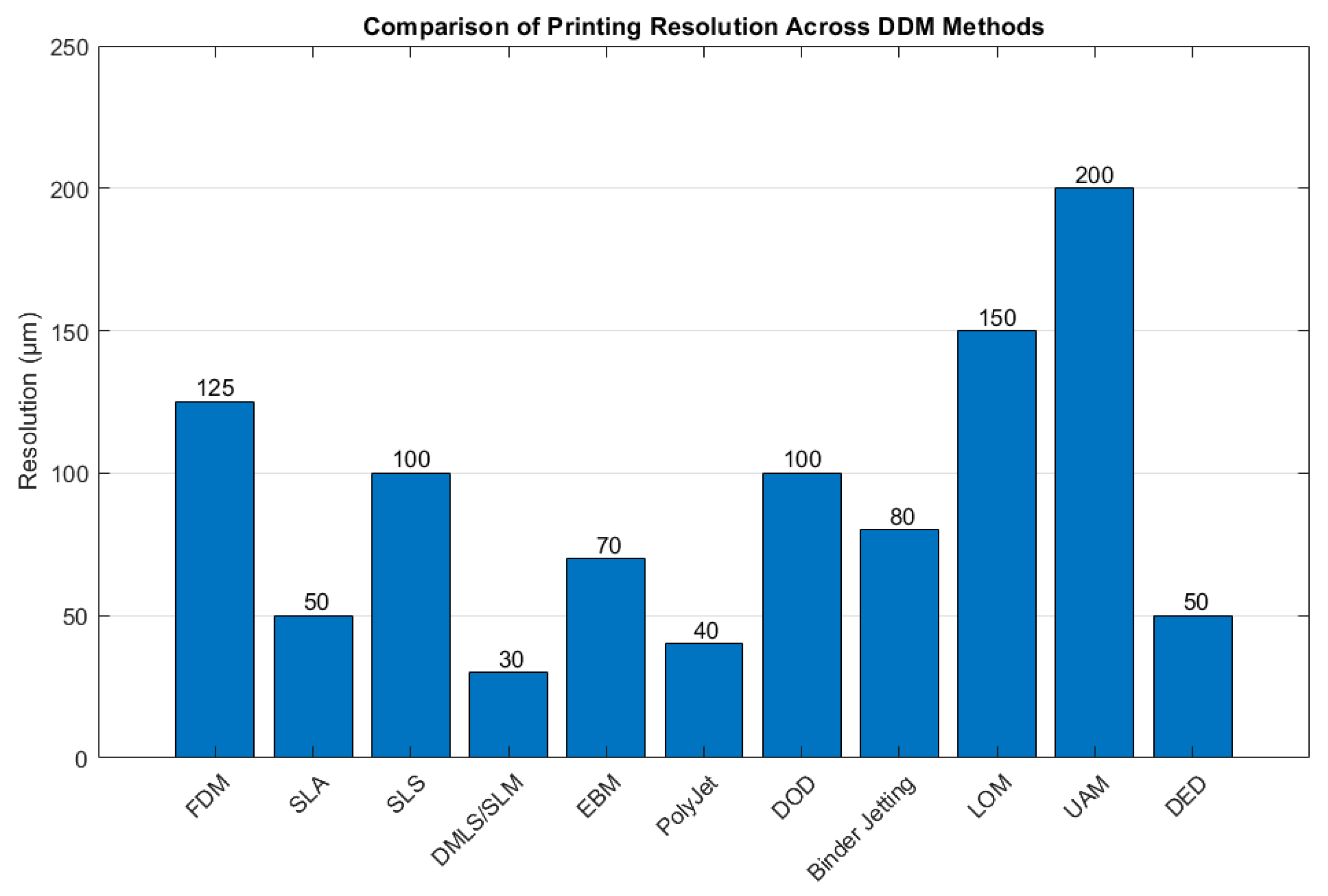
36]. Although layer precision can reach up to 100 µm, this figure may fluctuate based on the chosen equipment and technology, significantly impacting the resolution, patterning, and ultimately, the quality of the final output [
35].
Figure 1 delineates the categorization of DDM techniques as per the ASTM F2792 standard from the American Society for Testing and Materials [
35]. It visually represents the hypothetical average printing resolutions across various DDM methods [
35], demonstrating the spectrum of resolution capabilities characteristic of each method [
35]. Notably, lower numerical values denote a higher level of achievable precision, accentuating the diverse technological landscape within DDM practices [
35]. This underscores the imperative of selecting a fitting technique to meet specific accuracy demands [
35,
36]. Within this framework, technologies are classified based on operational principles including material extrusion, vat polymerization, powder bed fusion, and several others. Among these, selective laser sintering (SLS) is highlighted for its pivotal role across diverse sectors such as aerospace and healthcare [
35]. SLS is distinct for its ability to fuse powdered materials into solid, robust structures without the need for support constructs, thereby economizing on material and simplifying post-processing activities [
36].
SLS technology is lauded for producing parts with unparalleled strength and longevity, rivaling those manufactured through traditional means [
35,
36,
37]. It proves invaluable in generating functional prototypes, end-use products, and customized or low-volume items. The adaptability of SLS to materials like nylon augments part functionality, enhancing thermal and chemical resistance, as well as flexibility. Moreover, SLS encourages efficient batch production, nesting multiple parts within the build volume to drastically cut down lead times and production costs for bespoke and medium-volume manufacturing [
35,
36,
37]. The environmentally sustainable aspect of SLS, facilitated by the recyclability of unused powder, positions it as a forward-looking solution in additive manufacturing, marrying design ingenuity with substantial material properties [
35,
36,
37].
In pursuit of sophisticated manufacturing solutions for mm wave small cells necessitating elevated precision, SLS 3D printing emerged as the superior method [
35,
36,
37]. Sculpteo [
37], distinguished through thorough research, leads in providing SLS technology, offering an extensive array of powder-based materials such as plastic, nylon, and alumide [
36,
37]. Primarily utilizing PA 2200 or PA12 alongside various polyamide alternatives [
37], Sculpteo caters to a comprehensive range of manufacturing requisites [
37].
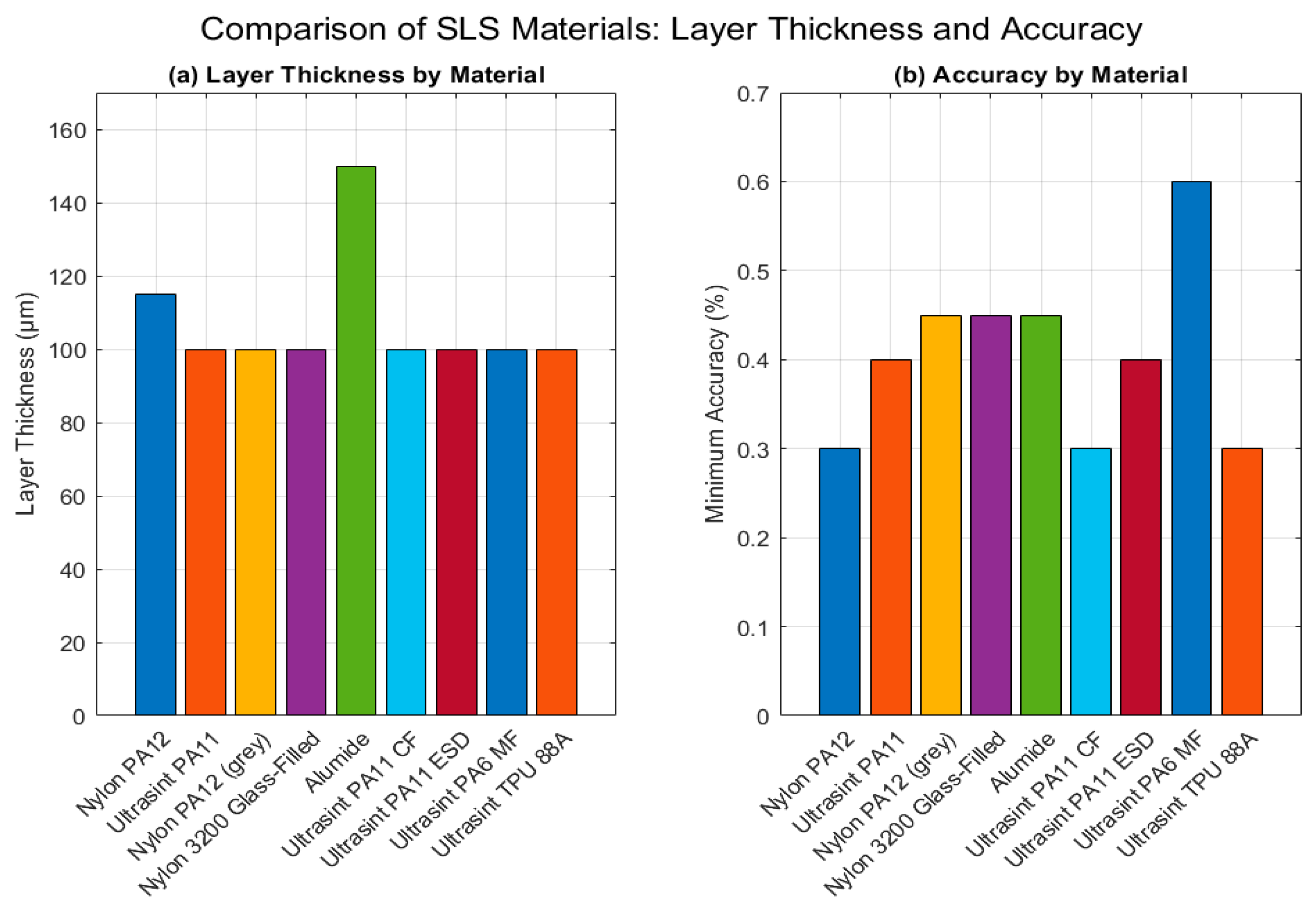
Figure 2 shows a comparative analysis of SLS materials [
3], revealing variations in layer thickness and precision among different materials [
37]. It demonstrates the high degree of precision achievable with SLS additive layering techniques and underscores the technology’s versatility to meet diverse engineering and design challenges. This is particularly relevant for applications like Luneburg lenses [
3,
17,
18,
19,
20,
21,
22,
23,
24,
25,
26,
27,
28,
29,
30], which require a specific permittivity range [
19], thus bypassing the need for inherently high-permittivity materials.
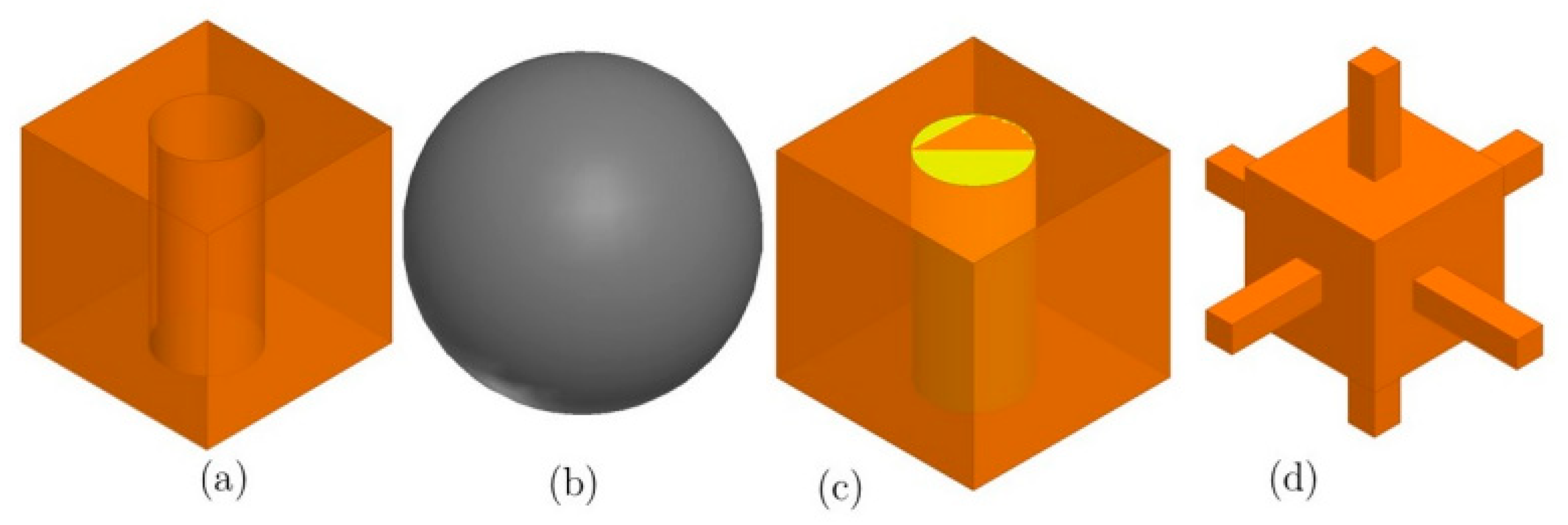
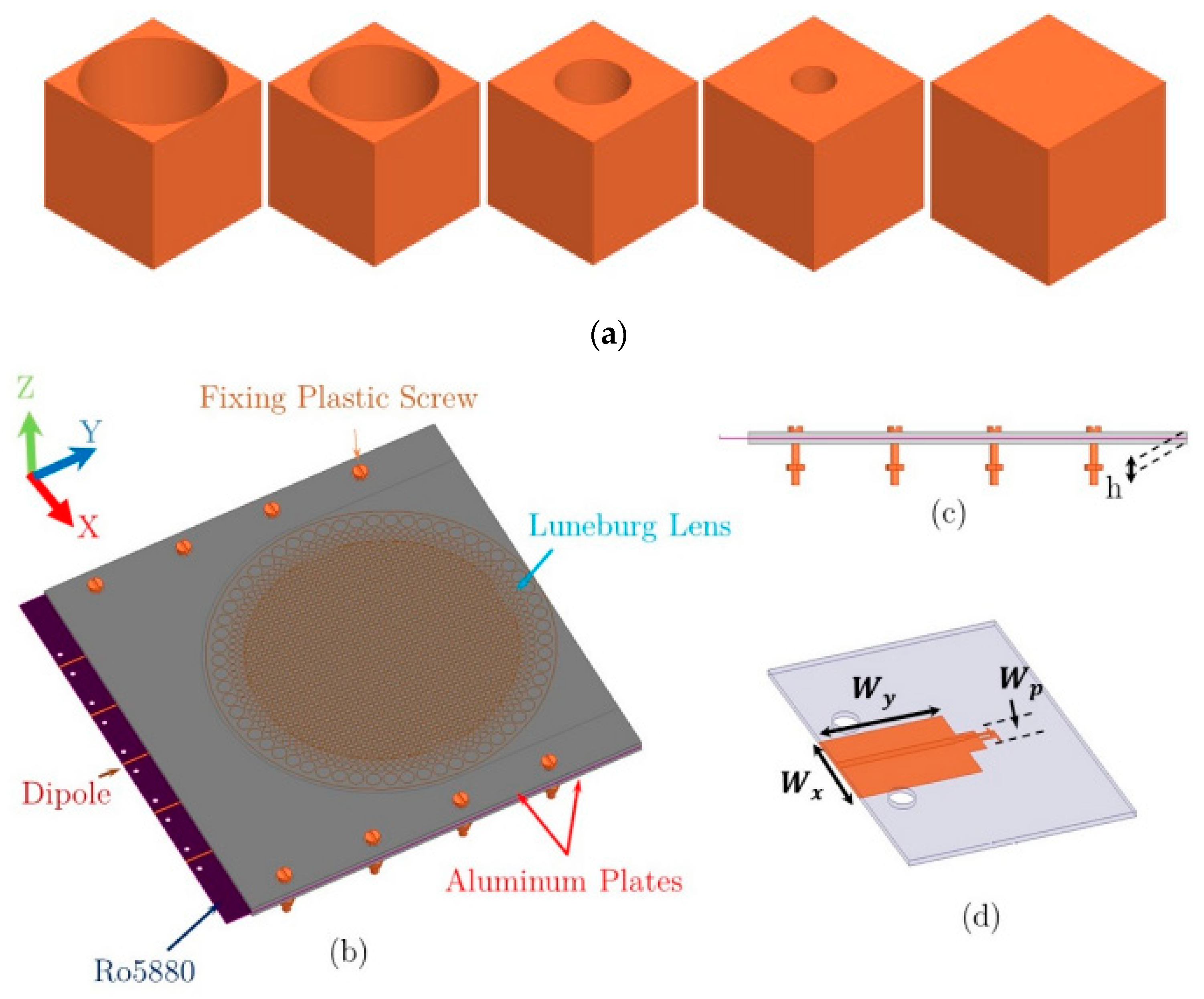
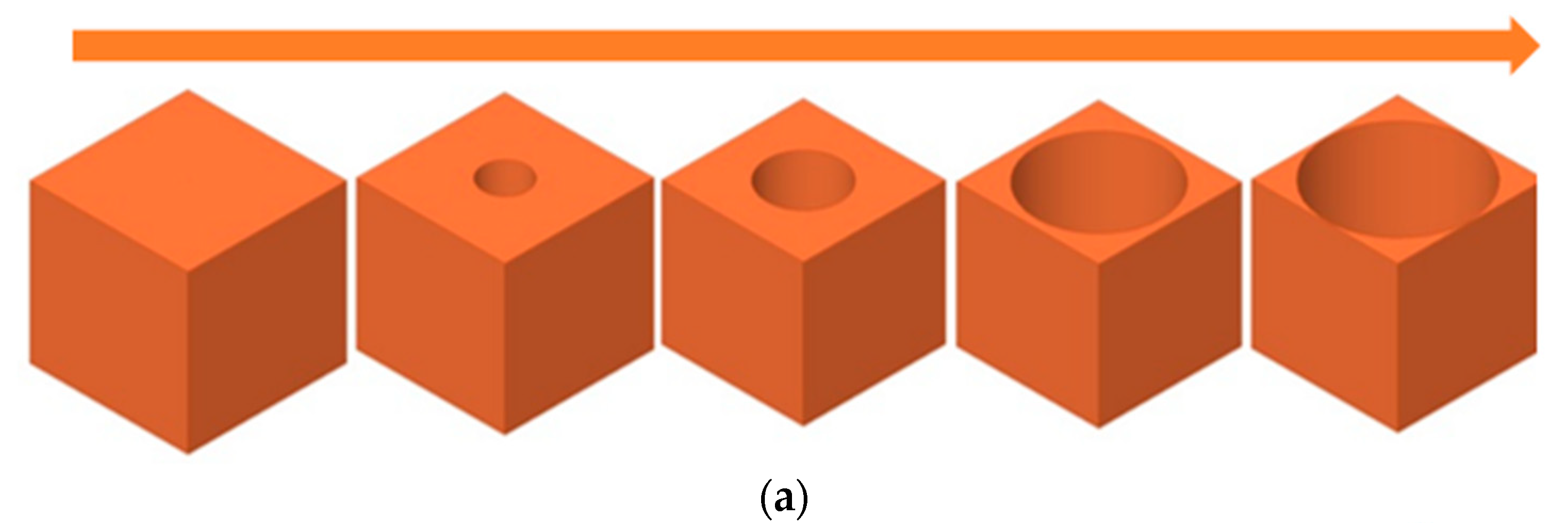
Figure 3 exemplifies four prevalent porous cell designs employed to create virtual permittivity environments [
3,
4,
7,
17,
18,
19,
20,
21,
22,
23,
24,
25,
26,
27,
28,
29,
30,
38,
39,
40,
41,
42,
43], enabling the manipulation of material ratios to attain specific permittivity levels. These designs facilitate the precise control of permittivity [
3,
4], allowing for the crafting of materials with tailored electromagnetic properties for various applications [
17,
18,
19,
20,
21,
22,
23,
24,
25,
26,
27,
28,
29,
30]. Techniques highlighted include the integration of air-hole cavities and the embedding of spherical metal cells, showcasing the potential of SLS technology to deliver customized, sustainable manufacturing solutions that herald a new era in additive manufacturing. In the development of this prototype [
3], certain particulars like the device number, code, or brand identifiers typically noted during manufacturing were not recorded. To ensure the highest accuracy and resolution, third-party verification was employed using ‘sculepto’ applications [
37]. The fabrication facilities of Sculpteo, a company based in France, were chosen, solicited, and compensated to precisely realize the envisioned design of the device.
This method is made possible by the incorporation of varied spherical volumes into the host medium for the purpose of a graded refractive index [
3,
17,
18,
19,
20,
21,
22,
23,
24,
25,
26,
27,
28,
29,
30]. Furthermore, as shown in
Figure 3c, the desired graded medium range can be increased by using components from the host medium that have a larger dielectric constant in liquid or powder form. As shown in
Figure 3d, this technique allows for dynamic control over virtual permittivity and can be applied to various material parts of the element for materials used in additive manufacturing [
3], leading to creative designs of GRIN lenses [
17,
18,
19,
20,
21,
22,
23,
24,
25,
26,
27,
28,
29,
30].
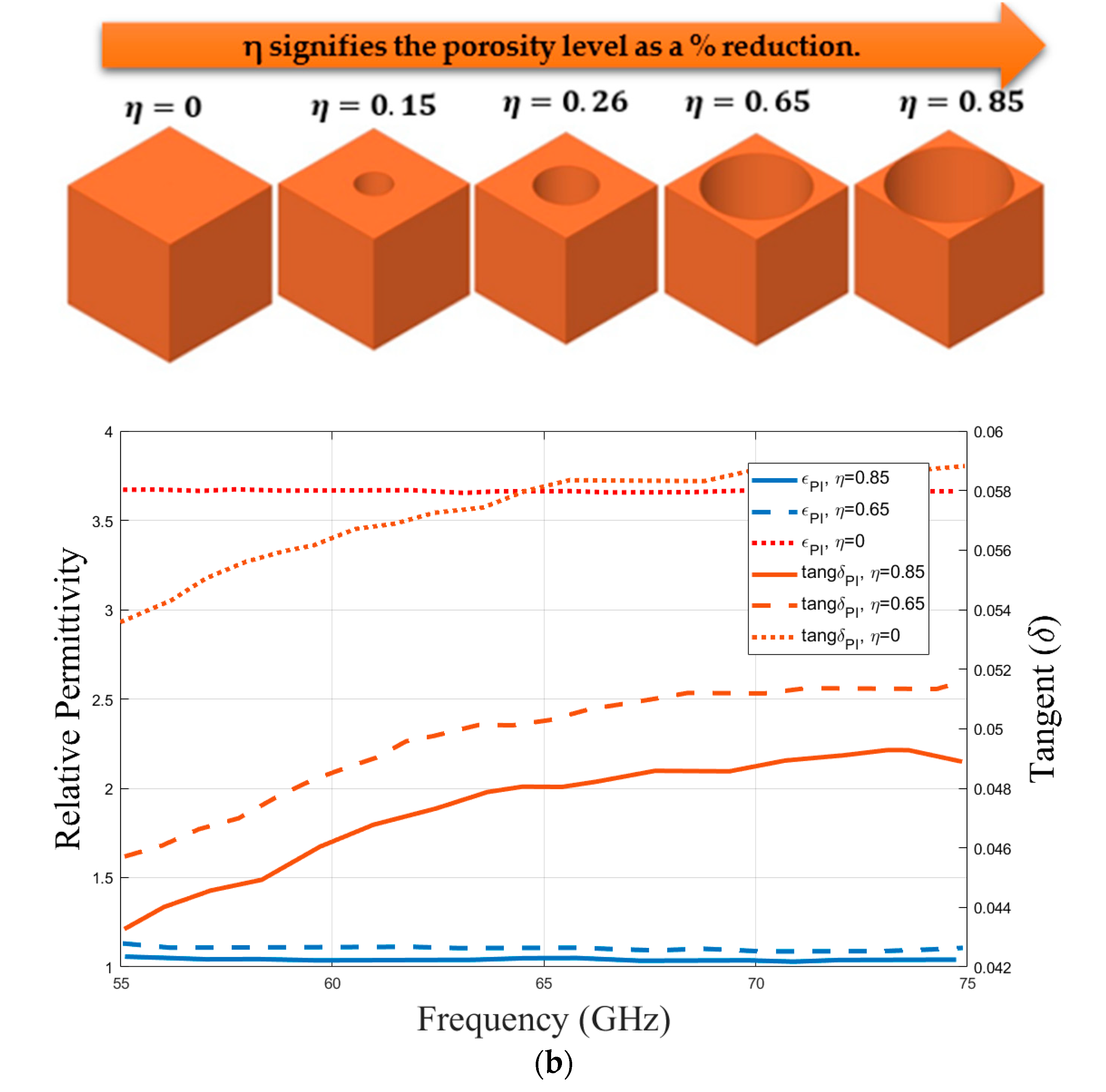
The broad range of refractive indices that can be achieved is made possible by the varied selection of material alternatives [
3], which includes PLA [
37], polyimide [
37], and ABS-M30 [
37]. This variety makes gradient index (GRIN) structures with porous frameworks easier to construct [
17,
18,
19,
20,
21,
22,
23,
24,
25,
26,
27,
28,
29,
30], as shown in
Figure 4a. Determining the dielectric coefficient of the surround environment within the intended frequency range is essential for the proper management and development of porous structures [
3]. To accomplish this, the spacer of a V-band waveguide measurement setup was filled with a 3.7 × 1.8 × 5 mm
3 polyimide sample [
37], which made it possible to extract expected material characteristics before building the GRIN structure, as shown in
Figure 4b. The proposed design leverages the selective laser sintering (SLS) manufacturing process to create porous cylindrical Luneburg lens cells, as shown in
Figure 5a,b [
37]. Utilizing an SLS printer, a prototype of the gradient refractive index (GRIN) structure is crafted, employing Sculepto’s 3D printing materials and device services [
37].
3. Luneburg Lens Design Concept and Mechanism
Recent advancements in additive manufacturing have led to a growing interest in tailoring gradient index (GRIN) distributions for designing focusing lenses [
17,
18,
19,
20,
21,
22,
23,
24,
25,
26,
27,
28,
29,
30]. Through adjustments in material porosity and the host medium [
3], it becomes feasible to create lens devices with both uniform and variable electrical characteristics [
17,
18,
19,
20,
21,
22,
23,
24,
25,
26,
27,
28,
29,
30]. In GRIN lens applications [
3,
17,
18,
19,
20,
21,
22,
23,
24,
25,
26,
27,
28,
29,
30], the incorporation of porous structures into homogeneous media presents a viable alternative to traditional dielectric lenses [
19]. This approach enables control over permittivity across the entire lens [
19], eliminating the dependence on a dielectric border medium [
17,
18,
19,
20,
21,
22,
23,
24,
25,
26,
27,
28,
29,
30]. Research on GRIN lens designs, including the Fresnel lens [
3,
4,
10,
23,
34], the half-Maxwell fisheye lens (HMFE) [
32,
33], and the Luneburg lens [
17,
18,
19,
20,
21,
22,
23,
24,
25,
26,
27,
28,
29,
30], focuses on the careful modification of permittivity effects in two- or three-dimensional arrangements to satisfy lens focusing requirements [
17,
18,
19,
20,
21,
22,
23,
24,
25,
26,
27,
28,
29,
30]. One of the best examples of gradient index (GRIN) optical devices is the Luneburg lens [
17,
18,
19,
20,
21,
22,
23,
24,
25,
26,
27,
28,
29,
30]. This device demonstrates how material porosity may be used in the microwave and millimeter-wave spectrum to improve antenna gain and shape beams [
7,
38,
39,
40,
41,
42,
43,
44,
45]. The refractive indices of both devices decrease radially and conform to a range of 1 ≤
≤ √2 [
19]. Equation (1) provides a full description of this radial distribution and is cited in [
17,
18,
19,
20,
21,
22,
23,
24,
25,
26,
27,
28,
29,
30] in the literature. Illustrated in
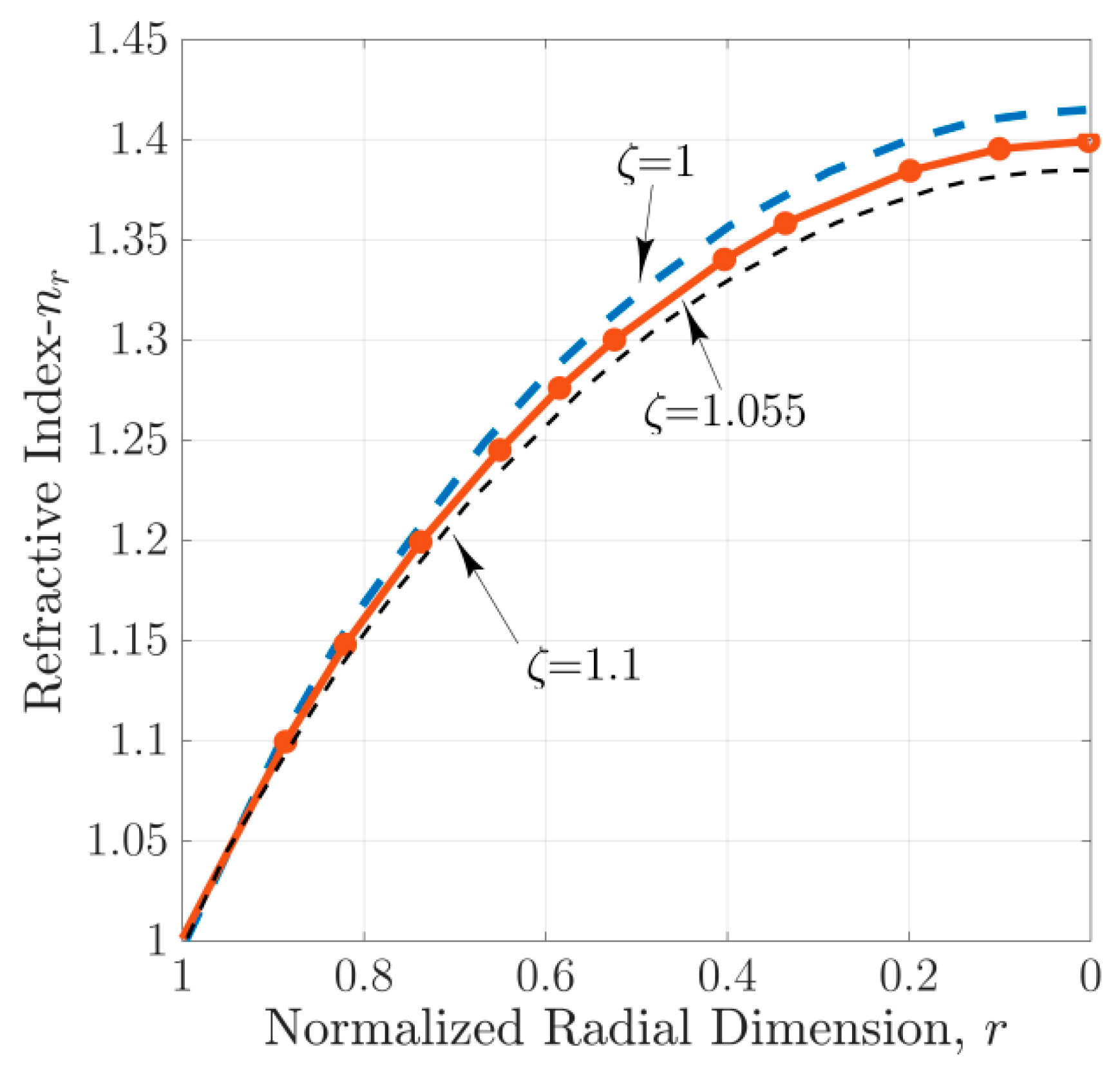
Figure 6 is the radial variation in the refractive index of the Luneburg lens, demonstrating a gradient that transitions from a value of 1.4 at its core to 1 at its outer edge.
Drawing from the principle of a spherically symmetric gradient index (GRIN) medium, the Luneburg lens operates within the realm of optics [
19]. Various wave launchers [
3], including coaxial-to-waveguide launchers and horn antennas, serve as primary light sources for this lens [
7,
17,
18,
19,
20,
21,
22,
23,
24,
25,
26,
27,
28,
29,
30,
38,
39,
40,
41,
42,
43,
44,
45]. Nonetheless, their application might result in bulkier antenna designs. Recent studies have investigated innovative pairings of wave launchers [
3], like microstrip lines, with metamaterial cell configurations in a hybrid approach [
11], aiming to manage the permittivity of individual subzones effectively [
11].
The design of GRIN devices is steered by the effective medium theory [
3], which employs a porosity-based method for controlling permittivity [
17,
18,
19,
20,
21,
22,
23,
24,
25,
26,
27,
28,
29,
30]. To ensure accurate analysis, this method relies on periodic porous unit cells, typically with diameters approximately one-tenth of the wavelength [
3,
17,
18,
19,
20,
21,
22,
23,
24,
25,
26,
27,
28,
29,
30]. Designers adeptly adjust the dielectric permittivity by integrating theoretical understanding with experimental data [
3,
17]. The distinct subsections [
19], as depicted in
Figure 4, that make up GRIN (gradient index) devices, can be adjusted independently [
3].
We introduce an enhanced version of the porous GRIN lens antenna [
3], which integrates polyimide nylon-based plastic into a parallel-plate waveguide (k) [
6,
31,
32,
33], along with a planar feeding platform meticulously tailored for optimal performance in 60 GHz applications [
3,
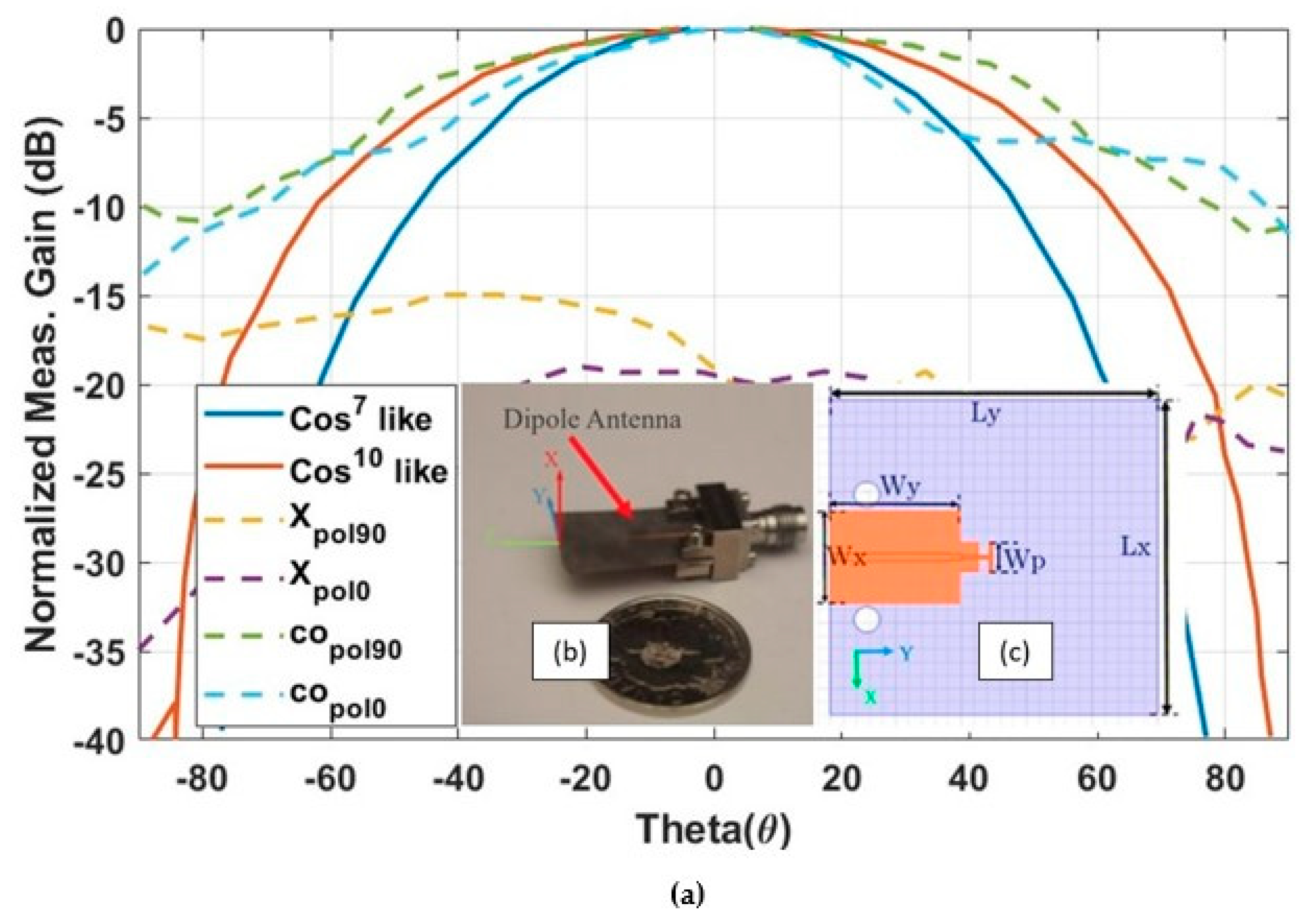
6]. These plastic lenses adopt a cylindrical design with a diameter of 13λ
0 and are illuminated by a dipole antenna generating a cos
10-like pattern [
3,
4], serving as the lens illuminator [
3]. Consisting of three essential elements—3D-printed Luneburg porous lenses [
1,
2,
3,
4,
5,
6,
7,
8,
9,
10,
11,
12,
13,
14,
15,
16,
17,
18,
19,
20,
21,
22,
23,
24,
25,
26,
27,
28,
29,
30], dipole antennas [
3], and parallel-plate waveguides—the dielectric lens antenna attains precise control over permittivity within a uniform medium via an innovative air-hole-based method [
3,
38,
39]. After conducting a comprehensive analytical evaluation of lens parameters [
3], we utilize additive manufacturing technology (ADM) [
35,
36,
37], in combination with selective laser sintering (SLS) [
37], for the fabrication process [
35]. The homogeneous lenses derived from polyimide plastic exhibits a relative permittivity (ε) of 3.57 and a loss tangent (tanδ) of 0.06 at 60 GHz [
35]. Based on the technical specifications provided by EOS Gmbh [
36] and Sculpteo [
37], the suggested permittivity value at a frequency of 10 GHz is documented to be 3.8 [
37]. By conducting a thorough examination [
3], the ideal diameter for the air holes has been pinpointed to ensure the attainment of the intended artificial permittivity throughout the uniform medium [
3,
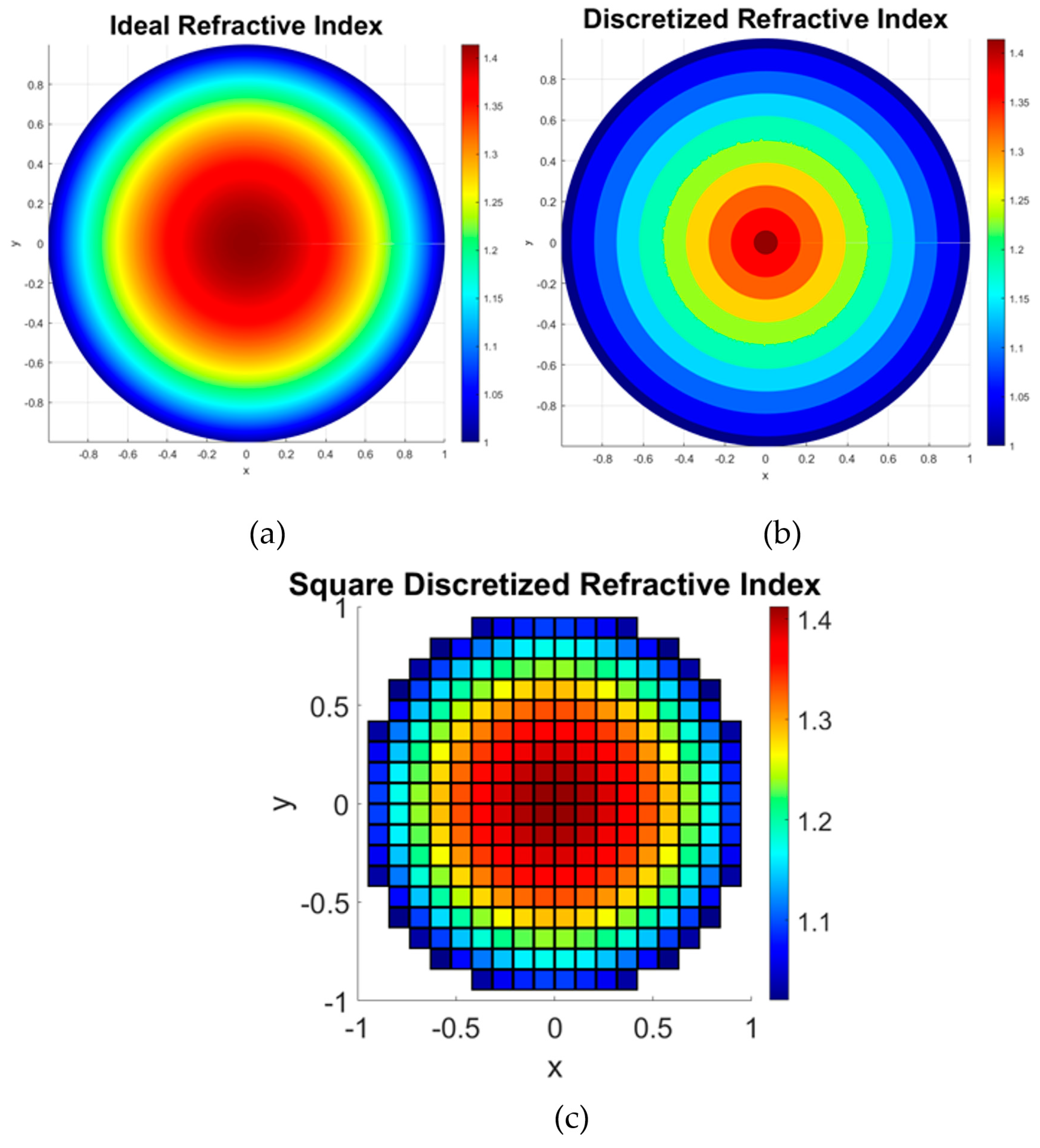
34]. This precision is applied to every discretized surface of the Luneburg lens [
3], which is discretized into square cells [
17,
18,
19,
20,
21,
22,
23,
24,
25,
26,
27,
28,
29,
30], as illustrated in
Figure 6c.
4. Designing Virtual Permittivity Using an Air-Hole Porous Approach
Moreover, the 3D graded index lenses have been fine-tuned for in-depth full-wave numerical electromagnetic simulations specifically tailored for 60 GHz operation [
3]. By leveraging effective medium theory, it is possible to ascertain the permittivity of these subzones by adjusting the porosity of the host medium [
17,
18,
19,
20,
21,
22,
23,
24,
25,
26,
27,
28,
29,
30]. As such, we advocate for the utilization of a Luneburg lens model that incorporates this methodology. Each lens subzone profile [
3], as shown in
Figure 6c, is divided into cells measuring 3 × 3 × 3 mm
3, constructed from plastic with cylindrical air pores [
3,
38,
39]. These layers are meticulously arranged to form virtual permittivity configurations within cubic cells [
3,
39], resulting in lenses composed of dielectric cells on a uniform platform that ensure operation over a broad frequency band.
The air-hole porous technique [
3,
34,
38,
39] was implemented on a polyimide concentric circular area utilizing selective laser sintering [
3,
4,
5,
6,
7,
8,
9,
10,
11,
12,
13,
14,
15,
16,
17,
18,
19,
20,
21,
22,
23,
24,
25,
26,
27,
28,
29,
30,
31,
32,
33,
34,
35,
36,
37]. This modeling technique was aimed to fulfill the Luneburg permittivity requirements of the layers at 60 GHz through the utilization of porous cells, as depicted in
Figure 5 [
3]. An in-depth analysis of aperture dimensions within the HFSS setup [
44] was crucial to the completion of the envisaged zonal system, which uses perforated dielectric cells [
3], as shown in
Figure 5. The radius of the air hole [
34], crafted using polyimide [
37], was chosen from the electro-optical systems’ [
36] catalog of materials to achieve the targeted refractive index (
) [
36], as illustrated in
Figure 2. One thick and one thin cell were employed to regulate permittivity [
3]. The diameter of the holes in both dielectric materials remained consistent at 4.2 mm, as shown in
Figure 5a,b, with “
” representing the hole radius and “d” denoting cell thickness [
3].
By adjusting the radius “
” of each air hole, we can determine the necessary dimensions for the virtual permittivity cell [
3]. Increasing the radius of the perforations in this design can lower the permittivity closer to that of air relative to the host medium (
. The determined air hole radius is used to model each zone according to Equation (1). Polyimide plastic has an inherent permittivity
= 3.6. Variations outside the specified cell range are indicated by changes in the radial diameters (r
a) and thickness (d) of the air holes to encompass various potential permittivities, as illustrated in
Figure 5 and
Figure 6.
Figure 4 demonstrates a control strategy for 3D cells capable of generating two types of cells through manipulation of material parameters to achieve different heights or radii. With known information groups regarding permittivity fluctuations and the radius of perforated holes (e.g., G1: (
); G2: (
)), hole dimension can be calculated via linear interpolation [
3]. The effective permittivities of the air-hole cells are approximated using linear interpolation based on volume reduction, as described by Equation (2), where
represents the host medium permittivity.
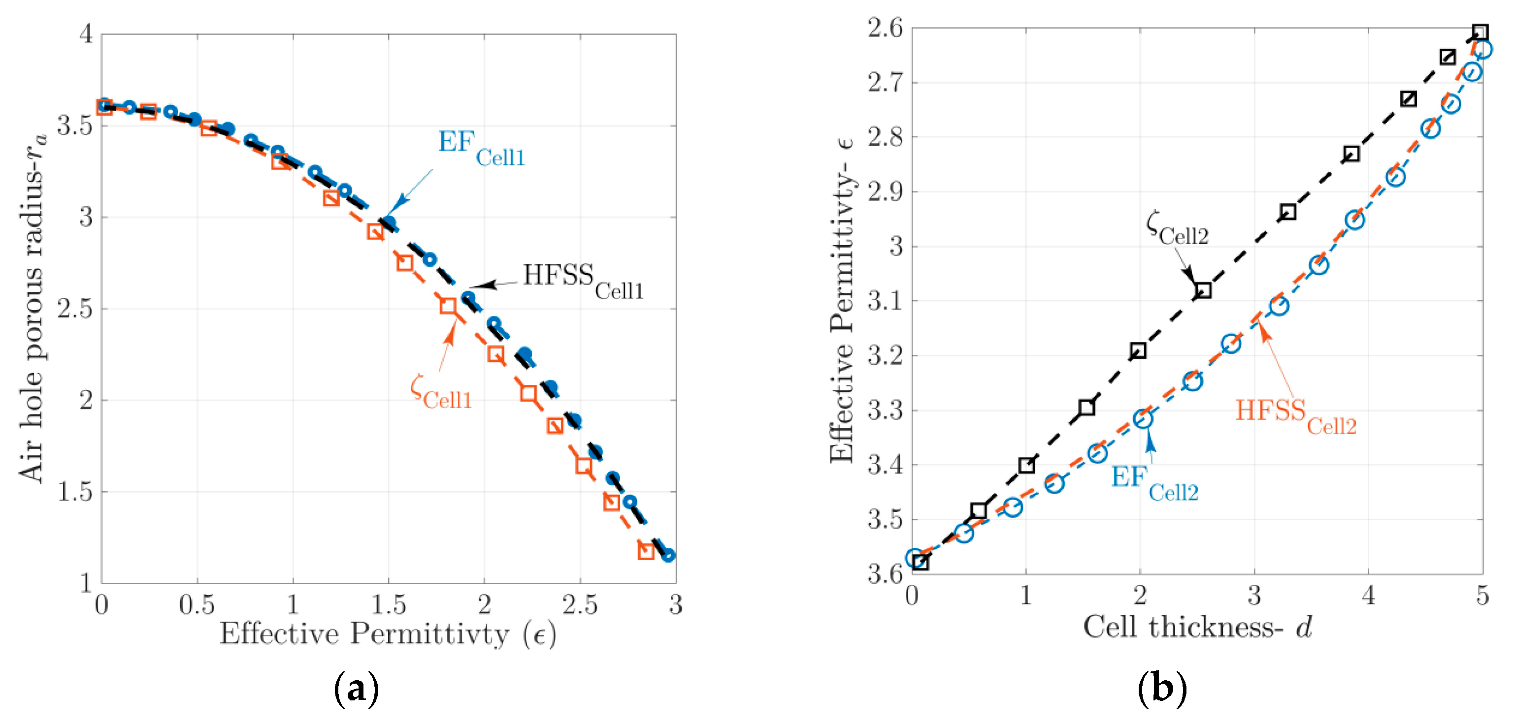
Figure 5 illustrate the suggested sizes and heights of air-permeable cells compared to the effective permittivity outcomes [
3].
The intrinsic permittivity of novel materials plays a crucial role in determining the final cell radius [
3]. Hence, it is necessary to carry out a distinct examination for each dielectric material. The findings indicate non-linear fluctuations in the discrepancies between radius and thickness compared to the desired permittivity [
3,
17,
18,
19,
20,
21,
22,
23,
24,
25]. Further investigation using full-wave simulations is required to enhance the accuracy of the anticipated virtual permittivity [
3,
4]. Ansys HFSS complete simulations are employed in a related experiment to accurately estimate cell values [
44]. The HFSS simulated waveguide configuration includes all dielectric porous cells of discrete radii [
3,
44], with perfect magnetic conductor (PMC) [
44] and perfect electric conductor (PEC) boundaries maintaining periodic conditions [
44]. Wave-ports are assigned to the right and left sides based on the specified configurations for these cells [
44]. The effective permittivity of scattering parameters is determined using the conventional retrieval approach involving Kramer–Kronig relations [
45].
It is important to note that the results comparing air-hole radius to permittivity for filling ratio and simulated setup effects in
Figure 4 are not directly comparable. To address this issue, we employ a mathematical fitting approach to improve the accuracy of determining radii, as shown in
Figure 5b [
3,
4,
40]. This method involves applying mathematical models to either experimental or simulated data to gain a deeper understanding of the fundamental linkages [
3,
4]. By employing linear fitting [
40], we can fine-tune parameters to ensure that the estimated outcomes closely align with the results obtained from simulated full-wave analysis [
17,
18,
19,
20,
21,
22,
23,
24,
25,
26,
27,
28,
29,
30]. This stage is essential for ensuring the precision and reliability of our modeling endeavors [
3].
The results produced by mathematical fitting (EF) are compared and analyzed with those from full-wave simulations. This comparison is crucial for validating our models and ensuring alignment between them before realizing the whole lens and antenna structure, as shown in
Figure 7 [
3].
5. Dielectric Lens Design and Feed
The implementation of the planar dipole feed is meticulously orchestrated to align precisely with the symmetrical geometric arrangement of the focal points on the perforated Luneburg lens’s surface. This strategic placement is crucial for ensuring a high degree of matching with similar techniques, as evidenced in References [
3,
6]. Previous methods employed to feed lens antennas have included a variety of approaches [
4], such as patch antennas, open waveguide antennas [
7,
40], horn antennas [
17,
18,
19,
20,
21,
22,
23,
24,
25,
26,
27,
28,
29,
30], and Vivaldi antennas [
6,
31,
32,
33]. However, a consistent challenge identified across all types of lens antennas [
19]—from those designed using conventional equations to those utilizing gradient refractive index (GRIN) lenses [
17,
18,
19,
20,
21,
22,
23,
24,
25,
26,
27,
28,
29,
30]—has been the lens feed itself, according to our research. Traditionally, lens antenna designs have predominantly utilized standard illuminators, as previously mentioned across various studies [
17,
18,
19,
20,
21,
22,
23,
24,
25,
26,
27,
28,
29,
30,
46]. In our previous work [
4], we conducted an analysis to determine the peak efficiency achievable with Fresnel-type GRIN lenses. Our findings revealed that efficiency and gain could be enhanced by adopting a two-pronged approach [
4]. The initial strategy employs illuminators with high gain that emit symmetrical patterns, facilitating a uniformly distributed feed throughout the lens diagram, which stands in contrast to the traditional use of rectangular horns or open waveguides as illuminators [
4,
46]. The subsequent approach focuses on minimizing errors that may occur during the design phase and in the discretization process of the lens diaphragm [
4,
46,
47].
Pursuing the first objective, we experimented with symmetric e- and h-plane horn antennas in [
4], which proved conducive to reaching our goal. For microstrip-type antennas [
11], this aim is attainable with traveling wave antennas [
3,
6], among which the Vivaldi antenna [
6] and the dipole are notable examples [
3]. Following the insights gained from our study [
4], we meticulously designed the feed illumination to produce a cos
10 pattern, which is optimal for symmetrically feeding the lens surface [
4]. This approach to design not only mitigates mismatch issues within individual subzones but also substantially improves the overall performance of the lens structures. By fine-tuning the feed to accommodate the lens’s specific contours and refractive variations [
46], we have managed to address the pivotal problem of feeding the lens antenna [
3,
4,
46], enhancing both the efficacy and gain of the system [
46]. The result is a more homogeneous energy distribution across the lens [
4], yielding a robust, high-performance antenna suited for demanding applications and the electromagnetic spectrum [
46].
5.1. Multibeam Mechanism
Within the field of antenna design theory, especially in the context of utilizing Luneburg lenses [
17,
18,
19,
20,
21,
22,
23,
24,
25,
26,
27,
28,
29,
30], traditional guidelines strongly emphasize the accurate alignment of feed sources with the lens’s focal points, ensuring they directly contact the lens surface for multibeam performance or beamforming applications. This strategic placement is essential for optimal beam configuration and even distribution of light.
This facilitates the emission of highly directed beams crucial for highly focused millimeter-wave lens antenna applications [
3,
4,
6]. In theoretical antenna design, especially when incorporating Luneburg lenses [
17,
18,
19,
20,
21,
22,
23,
24,
25,
26,
27,
28,
29,
30], established design norms traditionally recommend positioning feed sources precisely at the lens’s focal points to achieve direct interface with its surface. Such alignment is pivotal for optimal beam shaping and light distribution.
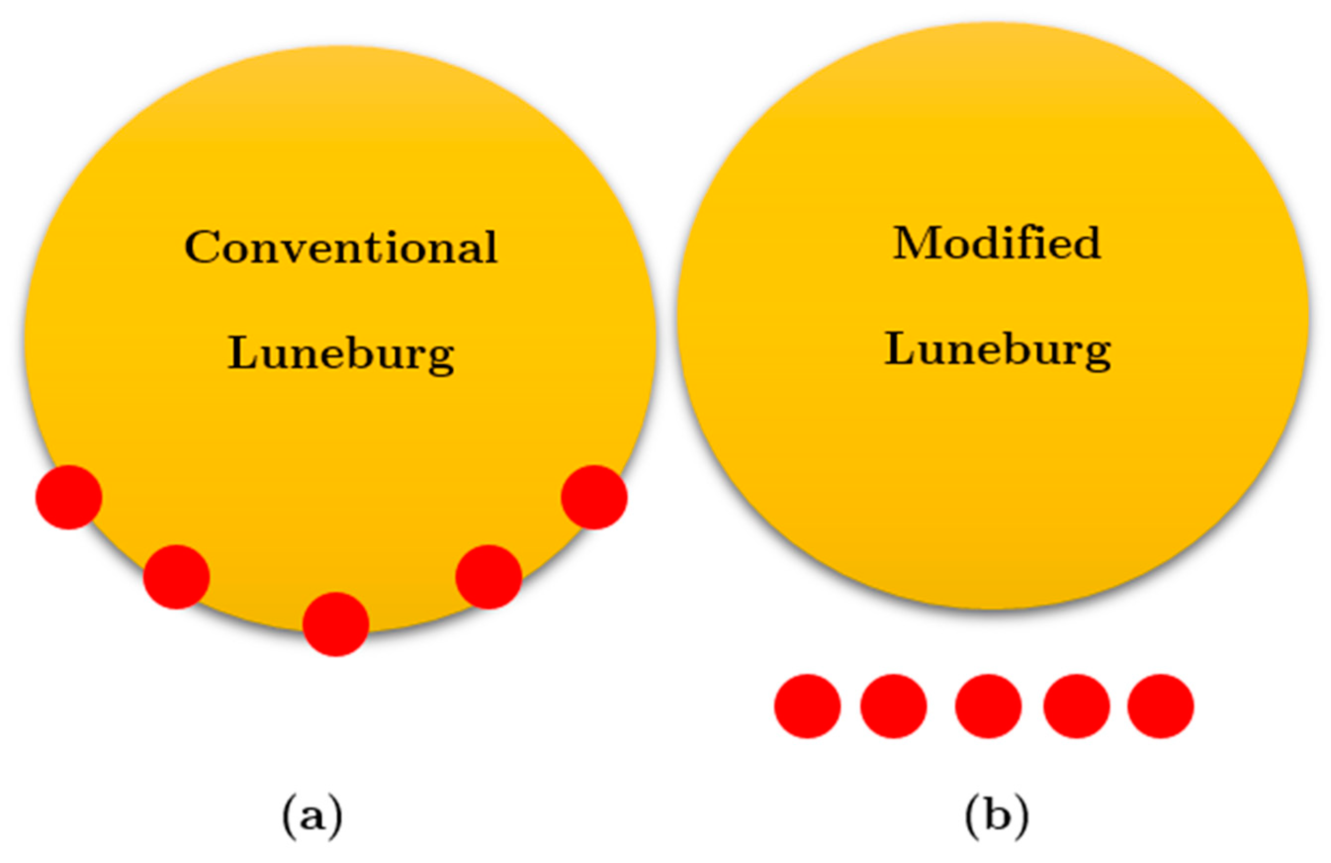
However, adherence to this guideline is frequently contested by design practicalities and the specialized requirements of distinct applications, necessitating the consideration of alternative setups. A notable deviation from standard practices involves the deployment of feed sources [
4], for instance, dipole antennas, at a remove from the lens surface, positioned in orientations divergent from the norm, like horizontally, as shown in
Figure 8. This shift from conventional alignment induces a defocusing effect but concurrently unlocks opportunities for novel design strategies that may present unique advantages under specific circumstances [
3,
47]. In navigating the intricacies and prospects presented by feed sources not directly engaging the lens, a series of strategies has been meticulously evaluated, each distinguished by its inherent strengths and challenges. Given the elaborate design possibilities of Luneburg lenses [
17,
18,
19,
20,
21,
22,
23,
24,
25,
26,
27,
28,
29,
30], which span both two-dimensional and three-dimensional constructs, a detailed approach to these unconventional designs is requisite [
17,
18,
19,
20,
21,
22,
23,
24,
25,
26,
27,
28,
29,
30]. Potential strategies unfold, including the fine-tuning of the lens’s refractive index gradient [
3], the crafting of hybrid lens architectures to facilitate a seamless permittivity transition from the lens’s exterior to its core [
11], and the calibration of beam configuration for defocused illumination [
47].
Nevertheless, the practical deployment of these strategies faces limitations rooted in the properties of materials and the specifics of manufacturing methodologies as reported in the literature [
17,
18,
19,
20,
21,
22,
23,
24,
25,
26,
27,
28,
29,
30,
46]. The needed permittivity variability for such design alterations is frequently unattainable with materials characterized by inherently high permittivity [
47], even with the advent of sophisticated manufacturing processes like selective laser sintering (SLS) 3D printing [
35,
36,
37]. This constraint is particularly pronounced in high-frequency ventures [
3], typified by operations at critical 60 GHz frequencies [
4], where porosity techniques—especially those employing a layered approach [
35,
36,
37]—and the orientation of incident waves [
3] (Chp.1), alongside cost considerations and the required dimensions for porosity cells [
4,
17,
18,
19,
20,
21,
22,
23,
24,
25,
26,
27,
28,
29,
30], might not yield the anticipated design objectives.
Our research thus pivots towards two innovative techniques [
3]. To facilitate a defocused illumination method [
46], we introduce a more directive lighting element, such as a cos
10 pattern dipole antenna, as discussed earlier. In situations where the feed source does not directly touch the lens surface and is not positioned at the standard focal points, illustrated in
Figure 8, utilizing intricate beam patterns such as cos
10 markedly enhances the performance of the system.
This methodology aims to harmonize the feed pattern with the Luneburg lens’s altered focusing dynamics [
17,
18,
19,
20,
21,
22,
23,
24,
25,
26,
27,
28,
29,
30], thus optimizing operational performance. The choice of a cos
10 pattern, more focused and directive compared to simpler configurations, promotes consistent illumination over the lens surface, effectively bridging the physical gap between the feed and the lens [
46]. This approach reduces sidelobes and amplifies the primary lobe’s intensity, enhancing both the directionality and focal precision of the emitted beam. Our analysis indicates that realigning the feed radiation pattern with the lens’s modified refractive index significantly boosts the efficiency of the antenna system. This continuing exploration into the impact of varying feed dimensions and strategies, coupled with the application of Cheng analysis for lens profile recalibration [
47], accentuates the potential of a defocused feeding approach to support multibeam functionalities [
46,
47]. Through meticulous research and design, we demonstrate that the dual adjustment of beam patterns to intricate configurations, such as cos
10, alongside lens profile alterations, can successfully implement a multibeam defocused feeding strategy, marking a significant advancement in antenna technology.
Upon mathematical analysis, we discovered a deviation of about 2 mm in the phase center of the perforated Luneburg lens from the intended lens boundary. Consequently, we adjusted the lens design to create a defocused Luneburg lens, albeit at the expense of aperture phase errors necessitating further refinement. This error is estimated as either a reduction in gain or inaccuracies in tilting angles [
3], as discussed in the report by Cheng [
47]. These errors are expected to amplify with an increase in the distance between the feed and the lens surface. Conversely, employing materials with a wide range of variable permittivity, which facilitates a smooth transition of the beam from the surface to the center of the lens and back, can mitigate these errors. To mitigate errors associated with the refractive index distribution, our approach utilizes the perforated Luneburg lens’s refraction function [
17,
18,
19,
20,
21,
22,
23,
24,
25,
26,
27,
28,
29,
30], integrating a permeable lens to enhance precision in analyzing and adjusting the refractive index profile. The essence of our strategy to minimize errors centers on two pivotal elements: adjusting the profile of the lens and utilizing a specialized beam type for illumination [
3], with the rationale for these choices being thoroughly explained [
3]. By adjusting the lens’s refractive properties [
47], it becomes feasible to accurately position an external point source relative to the lens type and structure. This configuration allows for the generation of a flat wavefront on the side of the lens opposite to the point source [
47], facilitated by the tailored refractive index profile of the perforated lens [
3,
4,
17,
18,
19,
20,
21,
22,
23,
24,
25,
26,
27,
28,
29,
30].
5.2. Optimizing Lens Design for Enhanced Beam Launching and Aberration Reduction
Cheng’s investigation into the defocusing mechanism is designed to improve beam launching efficiency and diminish the aberrations introduced by the lens’s structural design through a series of targeted adjustments and comprehensive analyses [
3,
47]. This summarized approach enables the tailoring of lens designs to meet the demands of specific fields, particularly for Internet of Things (IoT) technologies [
1]. A pivotal element of this optimization process is the detailed study of the lens’s performance, leveraging the refractive function
, with
as a parameter established by Equation (3) and enriched by the insights from Cheng’s research [
3,
47]. This method underscores our commitment to precisely fine-tuning the refractive index gradient of the lens [
47].
The objective centers on enhancing beam launching functions while simultaneously addressing and reducing the lens’s inherent aberrations. This ambition is pursued through a regimen of design iterations and exhaustive assessments. Each iteration is aimed at progressively refining the lens’s refractive index gradient, ensuring it more accurately aligns with our beam launching goals and effectively reduces the lens-induced aberrations. By adopting this structured and analytical approach, we aim to significantly improve the lens’s operational efficiency and accuracy, thereby validating the effectiveness of our strategies in rectifying errors related to the refractive index distribution.
This the potential strategy include the fine-tuning of the lens’s refractive index gradient.
In this analysis, the parameter
denotes the normalized distance from the point of interest to the center of the lens [
3,
47]. Under ideal conditions where the lens is adequately stimulated, the distance of the point source from the lens surface precisely equals
. This optimal distance facilitates efficient interaction between electromagnetic waves emitted from the point source and the lens surface, ensuring precise beam focusing.
By substituting
into Equation (3) [
3,
47], we derive the conventional refraction function. This function delineates the relationship between the refractive index of a lens and the distance of a point source from its center [
11], offering crucial insights into the lens’s behavior and aiding further study and development. The normalized distance ζ can deviate to
by altering the point source’s position beyond the surface of the perforated Luneburg lens, where ε represents a positive value [
47]. Departure from the ideal distance of
results in a displacement of the point source from the lens center [
17,
18,
19,
20,
21,
22,
23,
24,
25,
26,
27,
28,
29,
30], impacting the lens’s behavior and subsequent electromagnetic wave propagation [
3]. To accommodate variations in distance, we incorporate the unique distance function into the earlier equation, resulting in a customized refraction function tailored for the modified perforated lens [
47]. This revised refraction function accurately portrays the altered relationship between the point source and the lens due to the displacement, providing crucial insights into the lens’s performance across various operational scenarios. Equation (3) serves as a vital tool for analyzing and optimizing the modified lens’s performance in real-world situations [
47].
By integrating the detailed version of Equation (3) into the exponential refraction function
[
3], we derive Equation (4), which represents the refraction function designed for the defocused perforated lens with modified zone permittivity [
47]. This adjusted refraction function considers the deviation of the point source from the optimal position on the lens surface [
3,
47], incorporating the altered distance parameter
and the associated refractive index variations.
Figure 9 provides a visual representation of the defocused refraction function, showcasing how refractive values vary across different regions of the lens and beyond the beam launchers for varying
values [
3,
47]. Within the subzones of the lens, there is a consistent trend of lower refractive values, indicating a corresponding decrease in effective permittivity within these areas [
3,
47]. This finding corroborates previous research suggesting that adopting a lower virtual permittivity could enhance the overall design of this dielectric GRIN device [
3,
17,
18,
19,
20,
21,
22,
23,
24,
25,
26,
27,
28,
29,
30,
47]. Furthermore, Equation (4) offers a comprehensive analysis of the refractive properties specific to a defocused perforated lens by revisiting and refining Cheng’s initial calculations [
46,
47]. This analytical approach plays a pivotal role in refining and optimizing the proposed device, as it takes into consideration the altered permittivity distribution within the perforated structure [
3]. By integrating Equation (4) into the design process, engineers can gain deeper insights into how changes in permittivity impact the device’s performance and make informed decisions to achieve optimal results.
In this designed prototype, the Luneburg lens depicted in
Figure 6 and
Figure 7 with a radius R = 30
is tailored for millimeter-wave operation at 60 GHz with the refractive index profile explained in
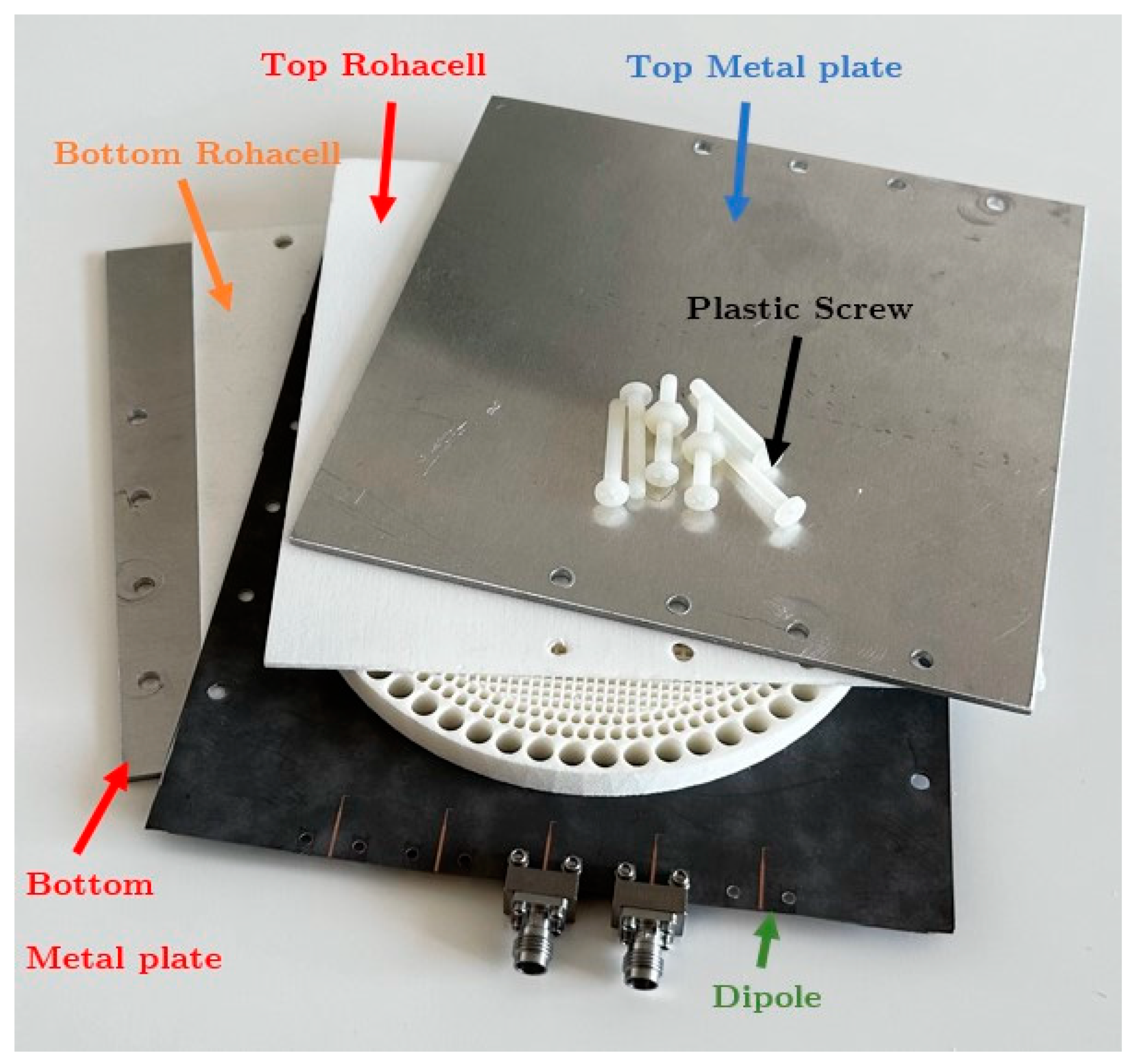
Figure 6c. Using a porous cylindrical structure as its foundational element, it facilitates the adjustment of polyimide’s intrinsic permittivity to meet the requirements of the perforated Luneburg lens subzones. Positioned between two parallel aluminum plates measuring 130 mm × 190 mm, the dielectric Luneburg lens operates at a frequency of 60 GHz, functioning in quasi-TEM mode within our experimental setup. Rohacell foam [
48] spacers in
Figure 7a with a permittivity of 1 at 60 GHz are employed to fill the gap between the aluminum plates, allowing for the dipole antenna to be suspended in air.
The design of the perforated Luneburg lens partitions the lens into four concentric cylindrical zones, each equipped with porous elements corresponding to specific virtual refractive indices. These indices (n) can range from 1.01 to 1.4 to adhere to the lens’s design principles. In the experimental setup depicted in
Figure 10 and
Figure 11, a microstrip-fed dipole antenna is utilized [
3,
4], featuring radiation patterns resembling cos
10 functions. This antenna is positioned between aluminum plates alongside the dielectric perforated Luneburg lens, creating a device adept at accurately directing electromagnetic radiation within the millimeter-wave frequency range.
The dipole antenna as an illuminator of the proposed lens surface is intricately crafted on a Rogers 5880 dielectric substrate of 0.5 mm thickness [
49]. The dipole and ground components were precisely etched onto the Rogers substrate to optimize antenna characteristics and generate a radiation pattern resembling a cos
10-like beam, crucial for accurate signal transmission. Securely nestled between two pieces of Rohacell foam [
48], the dipole antenna is aligned with the lens surface to ensure stability and enhance beam emission efficacy.
6. Step-by-Step Breakdown of the Perforated Lens Design Process
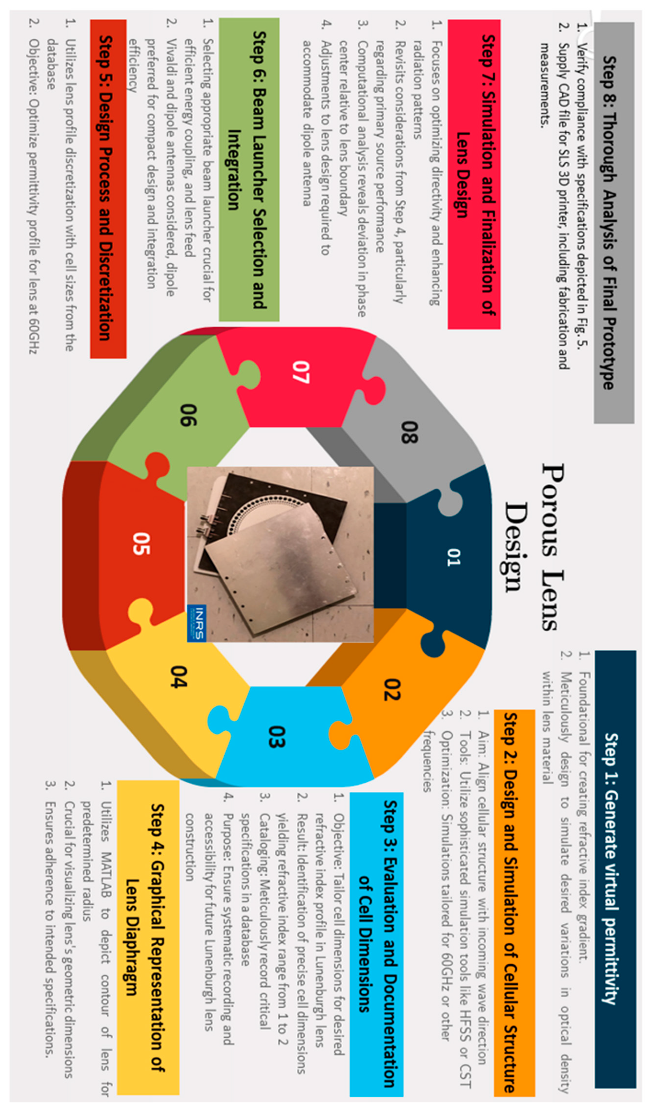
The outlined process encompasses a series of meticulous steps aimed at the design and fabrication of a porous Luneburg multibeam lens. These steps are condensed into a concise block diagram depicted in
Figure 12, comprising eight sequential stages essential for realizing the porous 3D lens.
Initially, Step 1 initiates the generation of virtual permittivity, a pivotal phase crucial for establishing a refractive index gradient essential in governing the behavior of incoming or incidence waves. Step 2 follows, meticulously crafting the cellular structure utilizing advanced simulation tools to ensure precise alignment with incoming waves. In Step 3, cell dimensions are thoroughly evaluated to attain the desired refractive index profile. This involves leveraging porous 3D printing materials, enabling the control of permittivity between air and the natural permittivity of the host medium, while meticulously cataloging critical specifications for future reference. Continuing onward, Step 4 involves the graphical representation of the Luneburg lens diaphragm to visually apprehend its geometric dimensions, a crucial aspect illustrated in
Figure 6. Step 5 delves into the discretization of the lens profile and the analysis of distinct layers, each filled with metamaterial cells, in the fabrication of the final GRIN lens, as demonstrated in
Figure 6. Subsequently, Step 6 encompasses the selection and integration of an efficient beam launcher, while Step 7 entails simulations aimed at optimizing directivity and enhancing radiation patterns. Step 8 encompasses necessary adjustments based on the outcomes of simulations, culminating in a thorough analysis of the final prototype to ensure it meets electromagnetic requirements. Finally, the creation and inspection of a prototype employing printed circuit board (PCB) technology are undertaken to guarantee meticulous quality control. Throughout this meticulous process, close attention is devoted to every detail to ensure optimal functionality of the multibeam modified planar Luneburg lens antenna with porous plastic material in transmitting signals.
Within the context of our analysis, it is evident that the block diagram represents a foundational framework common across all examined instances, albeit with minor enhancements or the delineation of additional steps to enhance calculation precision and accuracy. However, as highlighted in
Section 4, the most significant innovation or specialized focus of this study centers on selecting the appropriate beam illumination and mechanisms for defocusing. In reviewing the methodology of these steps, it becomes apparent that many studies do not venture into designing new cell structures or calculating permittivity anew [
17,
18,
19,
20,
21,
22,
23,
24,
25,
26,
27,
28,
29,
30]; rather, they rely on previously established material properties and/or frequencies, and then proceed directly to the implementation phase, as noted in the literature [
17,
18,
19,
20,
21,
22,
23,
24,
25,
26,
27,
28,
29,
30].
A prominent challenge in the development of GRIN lens mechanisms is the creation of a 3D prototype for simulation purposes, whether using HFSS or other software tools, which poses a considerable hurdle. Our proposed design incorporates over 700 cells, making it a simpler endeavor compared to other documented Luneburg lens designs, which may contain upward of 1500 cells. with spherical platforms instead of 2D platforms in this design. This complexity significantly increases the difficulty of identifying and rectifying errors during the printing and design phases, particularly in Steps 3 and 4, underscoring the challenges inherent in advancing GRIN lens technology.
7. Results and Discussion
The simulations and experiments performed on the suggested dielectric GRIN lens demonstrate a significant qualitative alignment between theoretical forecasts and real test outcomes. The analysis of the electric field distribution shows that the fields around the wave launcher are hidden by the strong radiation from the beam launcher, making it difficult to view the electric field in this setup. When incident waves pass through the lens structure, they transition from cylindrical waves to quasi-plane waves upon reaching the opposite side of the lens border, resulting in concentrated illumination.
Figure 13A,B vividly illustrate the beam focusing mechanisms of the perforated lens at both 60 GHz and 62 GHz, showcasing their complexity. Conspicuously, there are intense radiation patterns present at the documented frequency ranges. This thorough study highlights the effectiveness and reliability of the suggested dielectric GRIN lens design in real-world scenarios. The results shown in
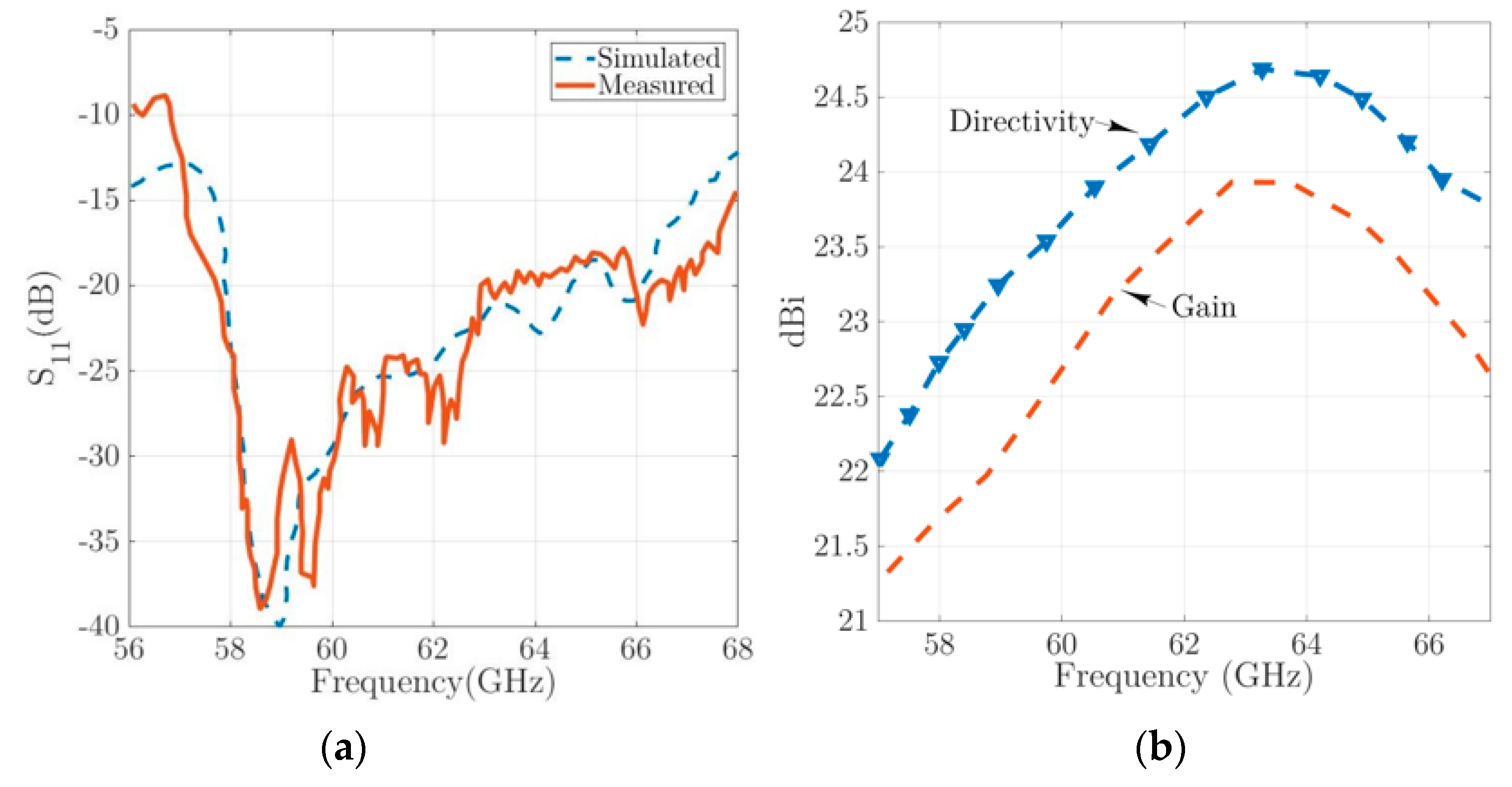
Figure 13 and
Figure 14, both computed and observed, regarding radiation patterns and S
11 parameters, are consistent with the expected performance of the customized perforated lens.
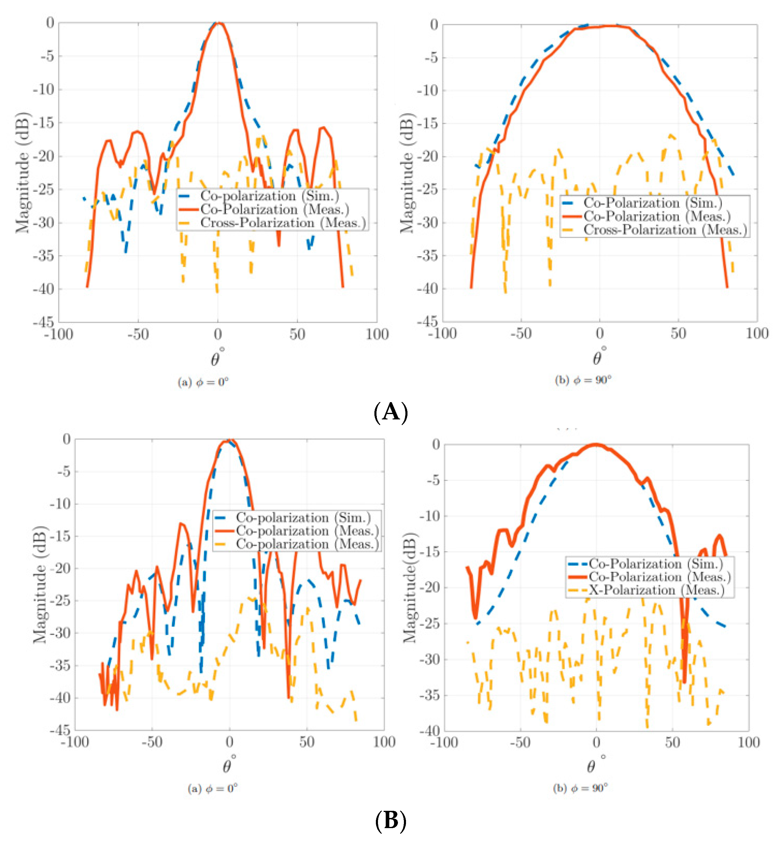
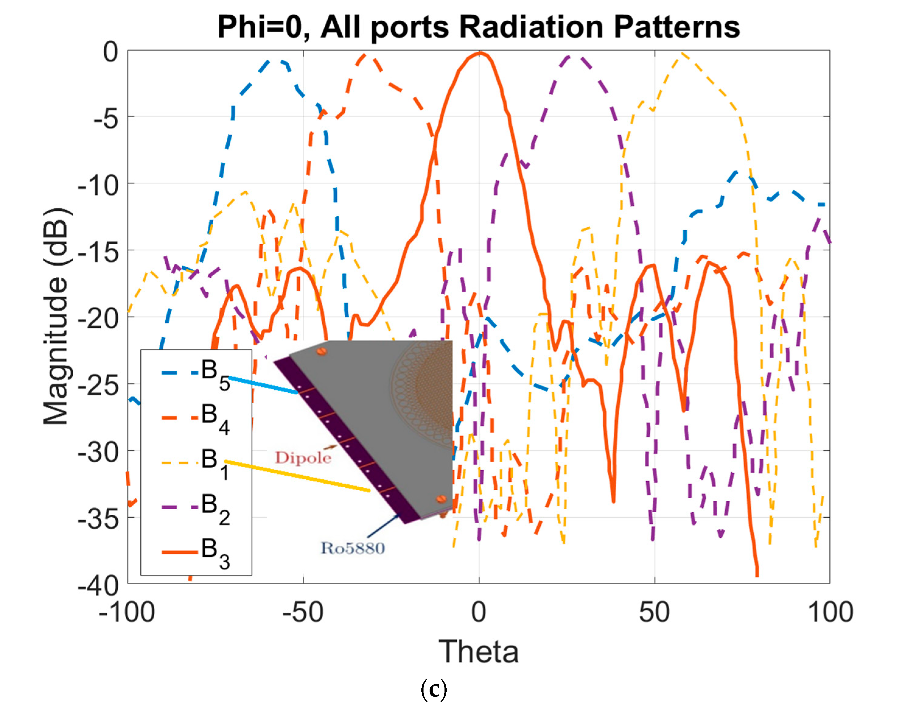
Figure 13 offers a detailed representation of the antenna’s radiation patterns at ph = 0 polarization, spanning across all specified ports (from port B5 to B1) tuned to a frequency of 60 GHz. This visualization includes angle scans at −67, −28, 0, 28, and 67 degrees, effectively demonstrating how the antenna directs radio waves in multiple directions. Through mathematical calculation and HFSS analysis, we identified a discrepancy of approximately 2 mm between the phase center of the perforated Luneburg lens and its designated boundary. This finding prompted us to reconfigure the lens design towards a defocused model, accepting the trade-off of encountering aperture phase errors that would require additional adjustments. Theoretical simulations predicted the beam’s radiation direction to ideally be at 0, 32, and 64 degrees. Nevertheless, practical measurements indicated that the lens’s focusing performance resulted in an approximate 4-degree deviation, accompanied by slight irregularities in beam shape. This was especially evident in the radiation patterns at 28 and −28 degrees, as depicted in
Figure 14, where the deviations from the expected cosine radiation patterns were markedly apparent.
Repeated measurements consistently highlighted these angular discrepancies. To address these issues, we can enhance lens optimization through the application of advanced optimization algorithms, such as genetic algorithms and Newton’s method techniques in future. These methodologies offer a systematic approach to refining the lens’s performance by iteratively adjusting design parameters towards optimal values in combine with HFSS simulations. Alternatively, a simpler immediate solution involves modifying the positioning of the linear array of dipole antennas to minimize the direction mismatch error. This adjustment aims to align the radiation pattern more closely with final expectations, thereby improving the lens’s overall focusing accuracy and beam quality. This feature evidences the antenna’s capability to emit beams along various paths, confirming its multibeam functionality, which is particularly advantageous for IoT applications operating at 60 GHz [
1]. Through mathematical analysis and full-wave simulation, it was determined that the feed phase center of the proposed lens should be aligned with the dipole antenna. It is essential to carefully construct the airgap using 1 mm thick Rohacell foam [
48], as even slight variations in thickness can have a notable impact on the desired effective medium properties surrounding the perforated lens.


