
A Circularly Polarized Complementary Antenna with Substrate Integrated Coaxial Line Feed for X-Band Applications

 and
and
Abstract
1. Introduction
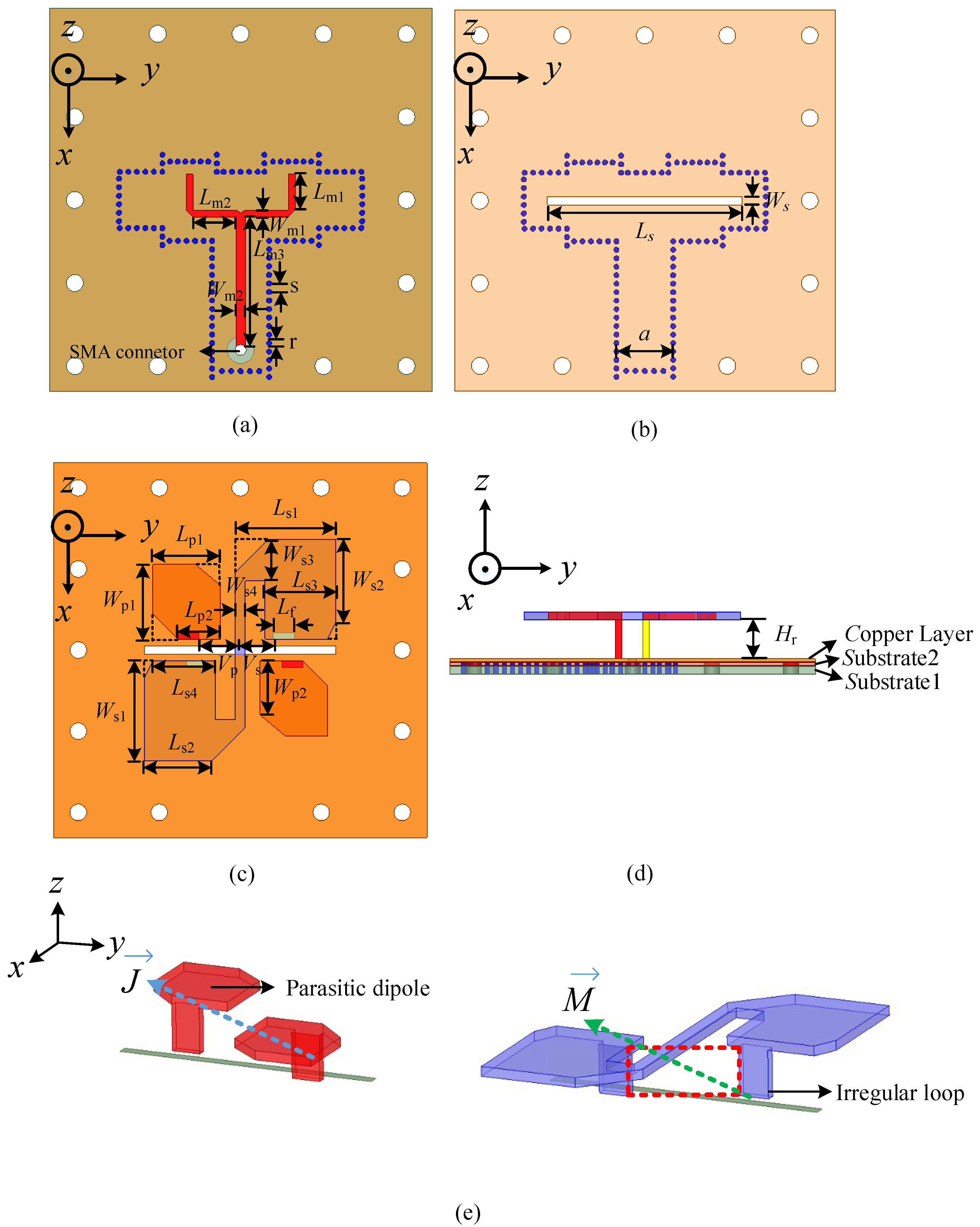
2. Antenna Design
3. Antenna Analysis and Parametric Study
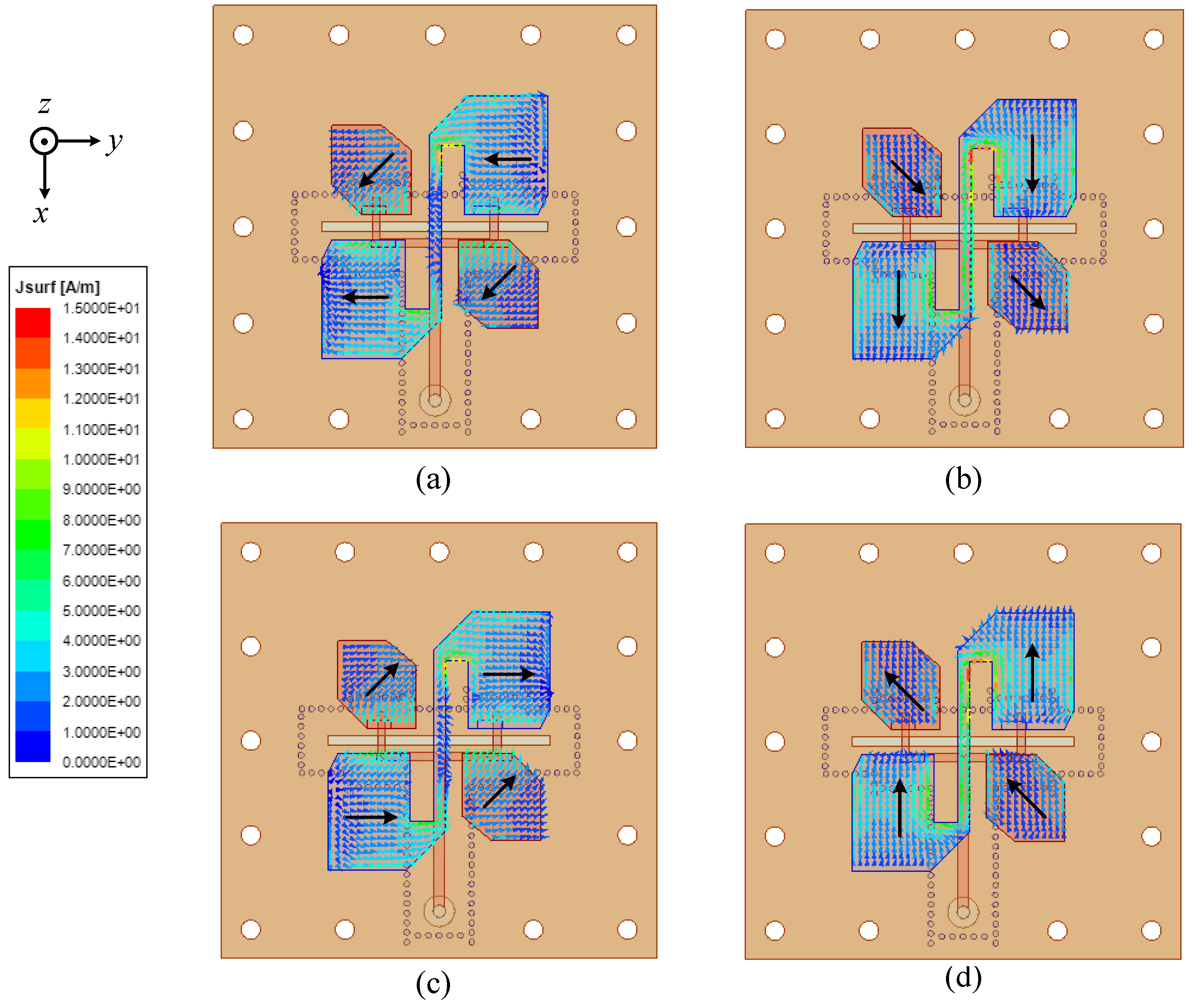
3.1. Antenna Analysis
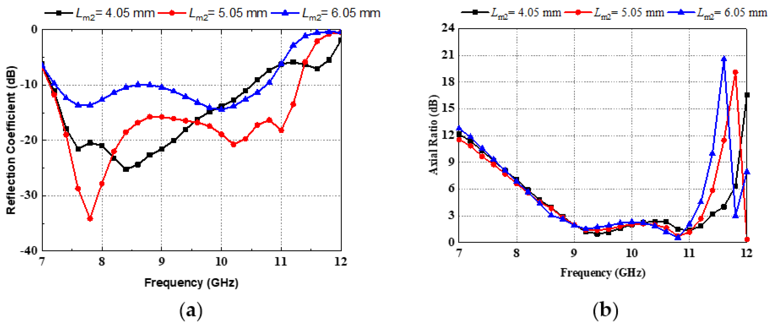
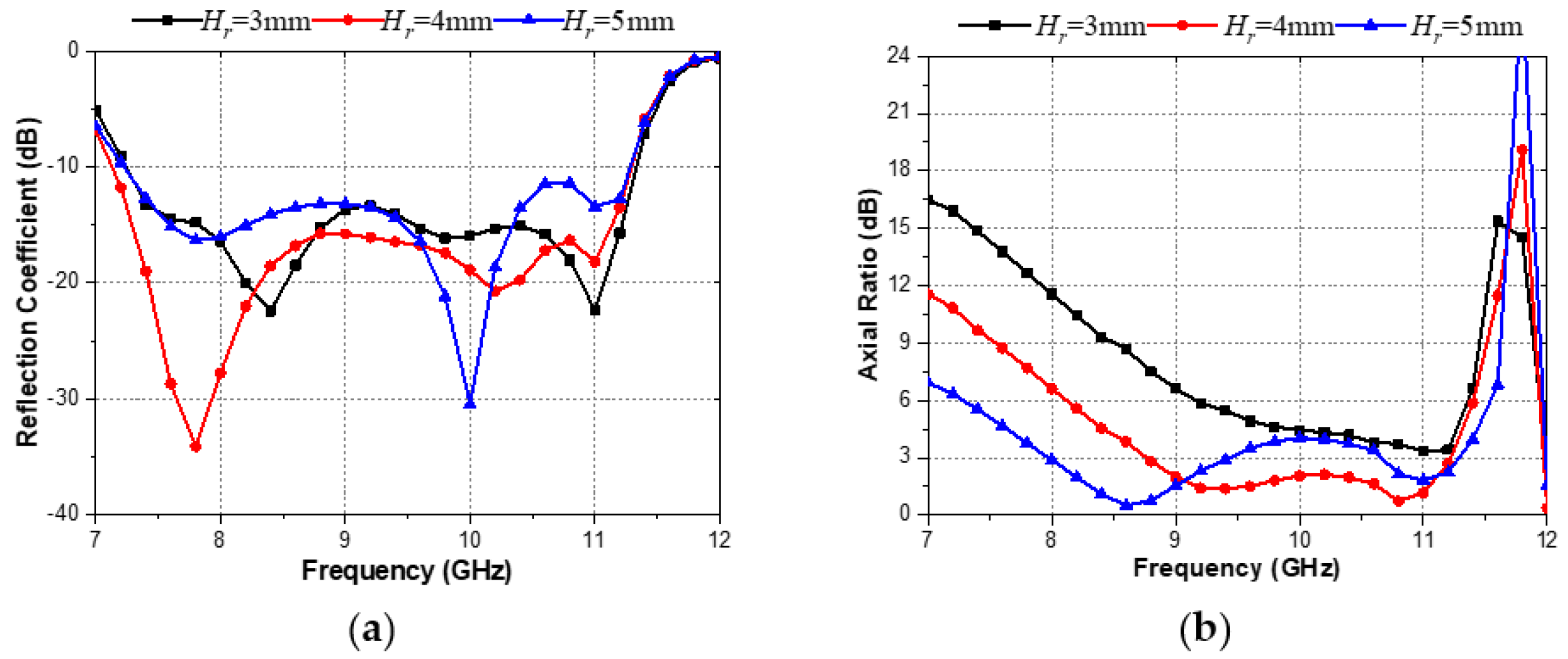
3.2. Parametric Study
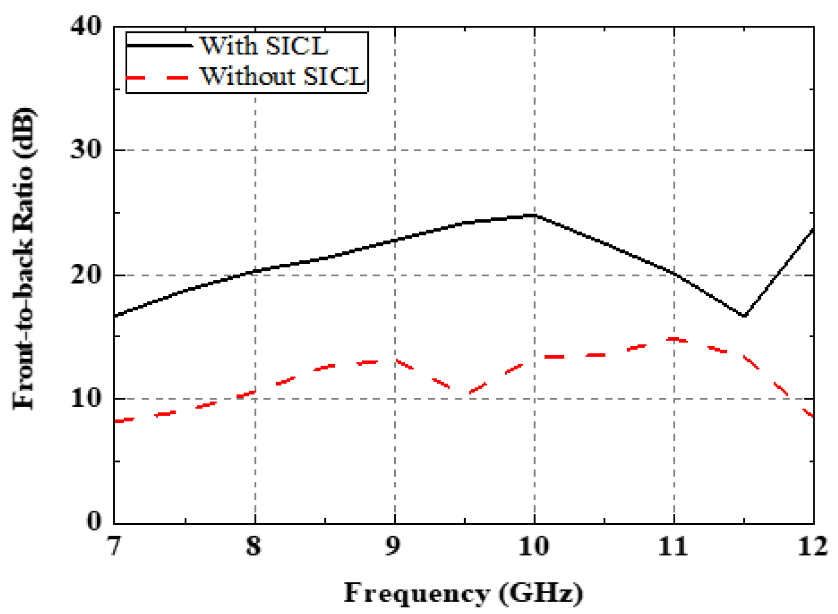
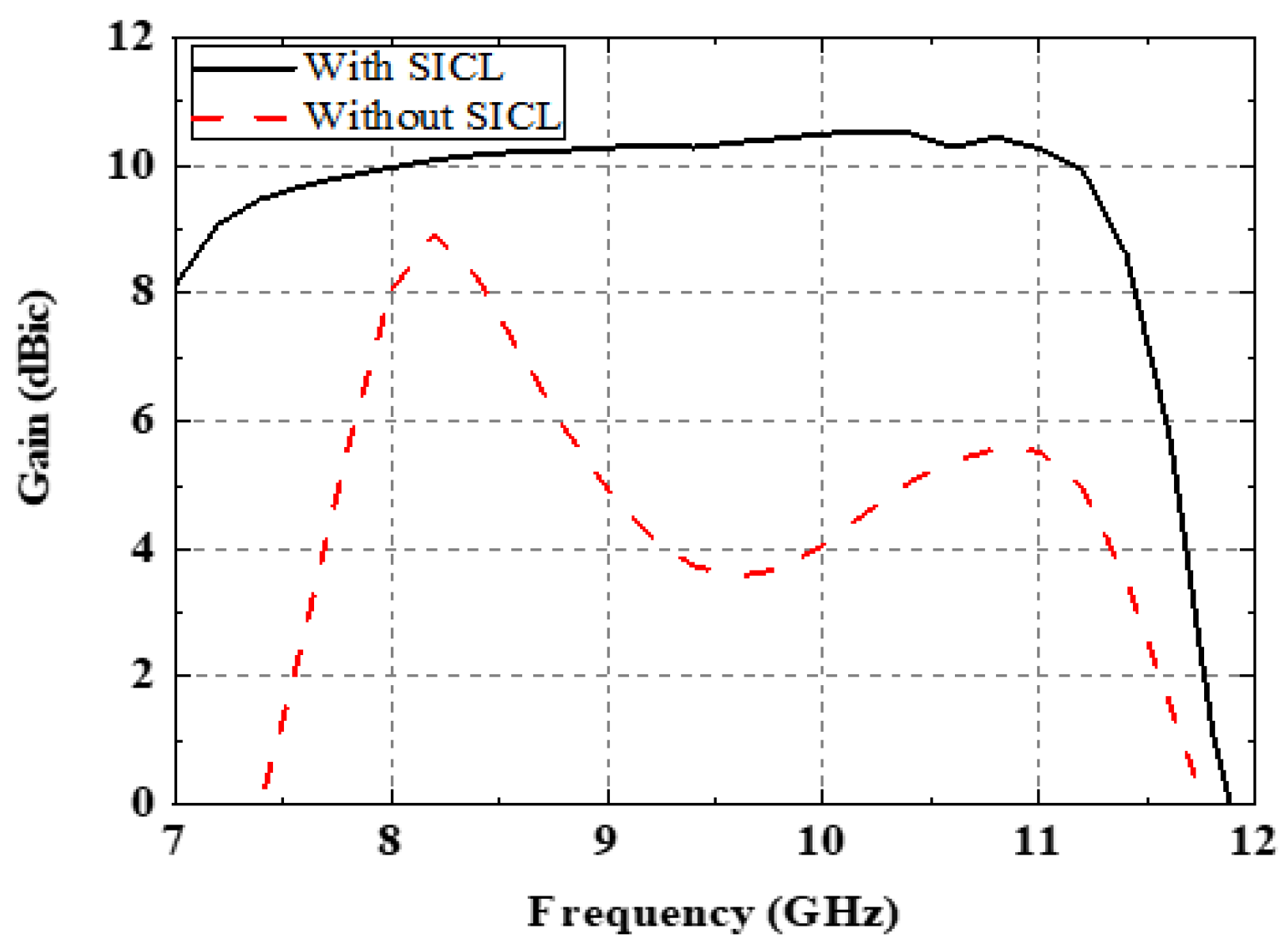
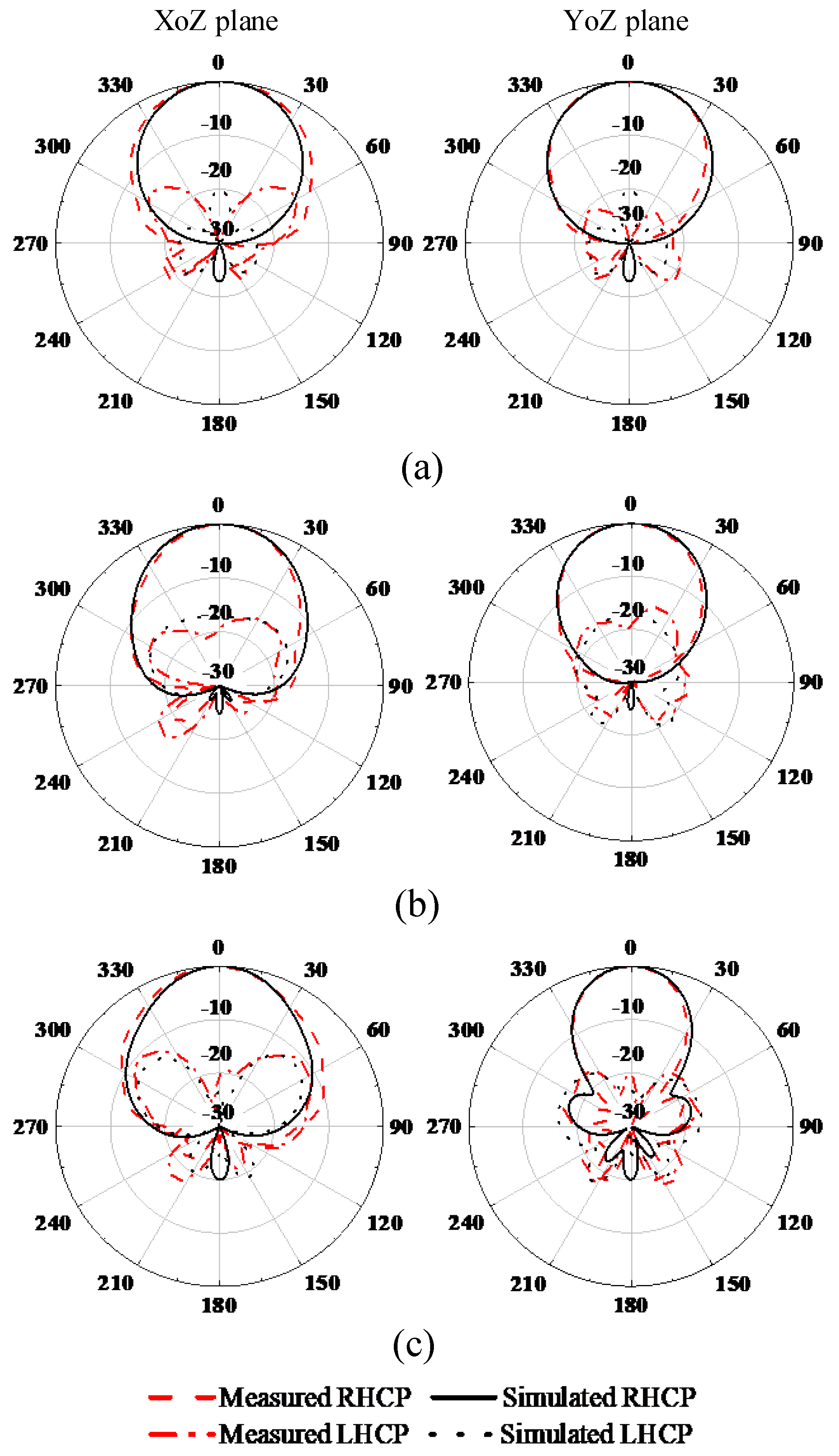
4. Measured Results and Discussion
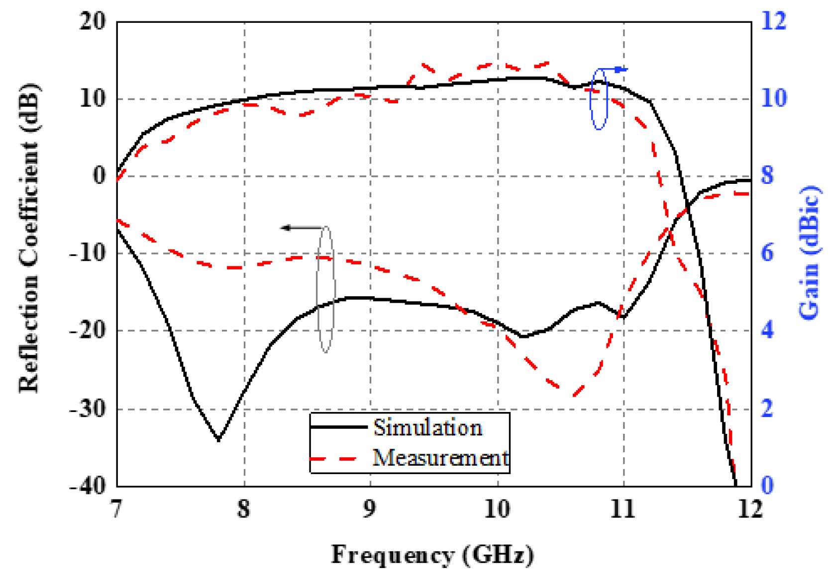
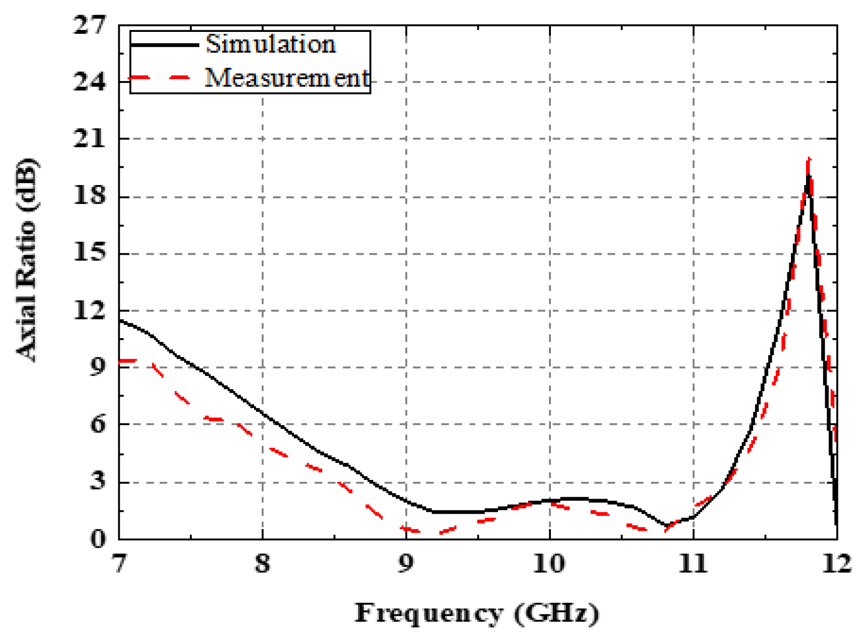
4.1. Measurement Results
4.2. Discussion
5. Conclusions
Author Contributions
Funding
Data Availability Statement
Conflicts of Interest
References
- Xu, Y.; Wang, Z.; Dong, Y. Circularly Polarized Slot Antennas with Dual-Mode Elliptic Cavity. IEEE Antennas Wirel. Propag. Lett. 2020, 19, 715–719. [Google Scholar] [CrossRef]
- Sun, J.; Luk, K.-M. A Circularly Polarized Water Patch Antenna. IEEE Antennas Wirel. Propag. Lett. 2020, 19, 926–929. [Google Scholar] [CrossRef]
- Lee, J.M.; Kim, S.-J.; Kwon, G.; Song, C.M.; Yang, Y.; Lee, K.-Y.; Hwang, K.C. Circularly Polarized Semi-Eccentric Annular Dielectric Resonator Antenna for X-Band Applications. IEEE Antennas Wirel. Propag. Lett. 2015, 14, 1810–1813. [Google Scholar] [CrossRef]
- Hall, P.S.; Dahele, J.S.; James, J.R. Design principles of sequentially fed, wide bandwidth, circularly polarised microstrip antennas. IEE Proc. H Microw. Antennas Propag. 1989, 136, 381–389. [Google Scholar] [CrossRef]
- Ta, S.X.; Park, I. Compact Wideband Sequential-Phase Feed for Sequentially Rotated Antenna Arrays. IEEE Antennas Wirel. Propag. Lett. 2016, 16, 661–664. [Google Scholar] [CrossRef]
- Sun, M.; Liu, N.; Zhu, L.; Fu, G. Wideband circularly polarized sequentially rotated microstrip antenna array with sequential-phase feeding network. J. Commun. Inf. Netw. 2020, 5, 350–357. [Google Scholar] [CrossRef]
- Yang, W.-J.; Pan, Y.-M.; Zheng, S.-Y. A Compact Broadband Circularly Polarized Crossed-Dipole Antenna with a Very Low Profile. IEEE Antennas Wireless Propag. Lett. 2019, 18, 2130–2134. [Google Scholar] [CrossRef]
- Li, M.; Luk, K.-M. A Wideband Circularly Polarized Antenna for Microwave and Millimeter-Wave Applications. IEEE Trans. Antennas Propag. 2014, 62, 1872–1879. [Google Scholar] [CrossRef]
- Sun, J.; Luk, K.-M. Wideband Linearly-Polarized and Circularly-Polarized Aperture-Coupled Magneto-Electric Dipole Antennas Fed by Microstrip Line With Electromagnetic Bandgap Surface. IEEE Access 2019, 7, 43084–43091. [Google Scholar] [CrossRef]
- Hui, H.; Ho, Y.; Yung, E. A cylindrical DR rod antenna fed by a short helix. In Proceedings of the IEEE Antennas and Propagation Society International Symposium, 1996 Digest, Baltimore, MD, USA, 21–26 July 1996; Volume 3, pp. 1946–1949. [Google Scholar]
- Ji, Z.; Wang, K.X.; Wong, H. Circularly Polarized Dielectric Rod Waveguide Antenna for Millimeter-Wave Applications. IEEE Trans. Antennas Propag. 2018, 66, 5080–5087. [Google Scholar] [CrossRef]
- Wang, J.; Li, Y.; Ge, L.; Wang, J.; Chen, M.; Zhang, Z.; Li, Z. Millimeter-Wave Wideband Circularly Polarized Planar Complementary Source Antenna with Endfire Radiation. IEEE Trans. Antennas Propag. 2018, 66, 3317–3326. [Google Scholar] [CrossRef]
- Wang, K.X.; Wong, H. A Wideband Millimeter-Wave Circularly Polarized Antenna With 3-D Printed Polarizer. IEEE Trans. Antennas Propag. 2017, 65, 1038–1046. [Google Scholar] [CrossRef]
- Wang, K.X.; Wong, H. Design of a Wideband Circularly Polarized Millimeter-Wave Antenna with an Extended Hemispherical Lens. IEEE Trans. Antennas Propag. 2018, 66, 4303–4308. [Google Scholar] [CrossRef]
- Chlavin, A. A new antenna feed having equal E -and H-plane patterns. Trans. IRE Prof. Group Antennas Propag. 1954, 2, 113–119. [Google Scholar] [CrossRef]
- King, R.; Owyang, G. The slot antenna with coupled dipoles. IRE Trans. Antennas Propag. 1960, 8, 136–143. [Google Scholar] [CrossRef]
- Luk, K.M.; Wong, H. A new wideband unidirectional antenna element. Int. J. Microw. Opt. Technol. 2006, 1, 35–44. [Google Scholar]
- Bai, X.; Qu, S.-W.; Ng, K.B. Millimeter-Wave Cavity-Backed Patch-Slot Dipole for Circularly Polarized Radiation. IEEE Antennas Wirel. Propag. Lett. 2013, 12, 1355–1358. [Google Scholar] [CrossRef]
- Ruan, X.; Qu, S.-W.; Zhu, Q.; Ng, K.B.; Chan, C.H. A Complementary Circularly Polarized Antenna for 60-GHz Applications. IEEE Antennas Wirel. Propag. Lett. 2017, 16, 1373–1376. [Google Scholar] [CrossRef]
- Lin, W.; Ziolkowski, R.W.; Baum, T.C. 28 GHz Compact Omnidirectional Circularly Polarized Antenna for Device-to-Device Communications in the Future 5G Systems. IEEE Trans. Antennas Propag. 2017, 65, 6904–6914. [Google Scholar] [CrossRef]
- Wu, Z.; Miao, Z.; Deng, X. High-Gain and Wideband Circularly Polarized Endfire Leaky-Wave Antenna Array Based on the Complementary Dipole. IEEE Trans. Antennas Propag. 2023, 71, 6168–6172. [Google Scholar] [CrossRef]
- Xu, J.; Luk, K.-M.; Hong, W. Low-Profile Wideband Circularly Polarized Complementary Antenna and Arrays for Millimeter-Wave Communications. IEEE Trans. Antennas Propag. 2023, 71, 2052–2063. [Google Scholar] [CrossRef]
- Gatti, F.; Bozzi, M.; Perregrini, L.; Wu, K.; Bosisio, R.G. A novel substrate integrated coaxial line (SICL) for wide-band applications. In Proceedings of the 2006 European Microwave Conference, Manchester, UK, 10–15 September 2006; pp. 1614–1617. [Google Scholar]
- Miao, Z.-W.; Hao, Z.-C. A Wideband Reflectarray Antenna Using Substrate Integrated Coaxial True-Time Delay Lines for QLink-Pan Applications. IEEE Antennas Wirel. Propag. Lett. 2017, 16, 2582–2585. [Google Scholar] [CrossRef]
- Liu, B.; Ma, Y.; Zhao, R.R.; Xing, W.Q.; Guo, Z.J. A Novel Substrate-Integrated Coaxial Line Transverse Slot Array Antenna. IEEE Trans. Antennas Propag. 2019, 67, 6187–6192. [Google Scholar] [CrossRef]
- Dai, X.; Li, A.; Luk, K.M. A Wideband Compact Magnetoelectric Dipole Antenna Fed by SICL for Millimeter Wave Applications. IEEE Trans. Antennas Propag. 2021, 69, 5278–5285. [Google Scholar] [CrossRef]


| Para. | Value | Para. | Value | Para. | Value |
|---|---|---|---|---|---|
| Lm1 | 4.2 | a | 6.7 | Ls1 | 12.1 |
| Lm2 | 5.05 | Ls | 23 | Ls2 | 7.1 |
| Lm3 | 15.25 | Ws | 1 | Ls3 | 8.5 |
| Wm1 | 0.8 | Lp1 | 8.1 | Ls4 | 7.5 |
| Wm2 | 1.1 | Lp2 | 5.1 | Ws1 | 12 |
| s | 1 | Wp1 | 9 | Ws2 | 9.5 |
| r | 0.3 | Wp2 | 6 | Ws3 | 5 |
| Vp | 5 | Vs | 4 | Lf | 2.5 |
| Hr | 4 | Ws3 | 1.2 |
| Ref. | Antenna Type | Imp. BW (%) | ARBW (%) | Max. Gain (dBic) | Gain Variation (dBic) | Height | Backlobe (dB) | Cross-Polarization (dB) |
|---|---|---|---|---|---|---|---|---|
| [7] | Cross-dipole | 61.8 | 51.6 | 4.03 | <2 | 0.067λ0 | −6 | −16 |
| [8] | Magneto-electric dipole | 56.7 | 41 | 9.9 | 4.9 | 0.15λ0 | −22 | −10 |
| [18] | Patch-slot dipole | 14.5 | 15.7 | 11.2 | 3.2 | 0.1λ0 | −25 | −10 |
| [19] | Complementary antenna | 23.8 | 23.4 | 8.6 | 3.3 | 0.15λ0 | −20 | −10 |
| [22] | Complementary antenna | 32.7 | 30.9 | 7.95 | 2.5 | 0.21λ0 | −8 | −5 |
| This work | Complementary antenna | 39.6 | 27.4 | 10.5 | 0.6 | 0.125λ0 | −25 | −16 |
Disclaimer/Publisher’s Note: The statements, opinions and data contained in all publications are solely those of the individual author(s) and contributor(s) and not of MDPI and/or the editor(s). MDPI and/or the editor(s) disclaim responsibility for any injury to people or property resulting from any ideas, methods, instructions or products referred to in the content. |
© 2024 by the authors. Licensee MDPI, Basel, Switzerland. This article is an open access article distributed under the terms and conditions of the Creative Commons Attribution (CC BY) license (https://creativecommons.org/licenses/by/4.0/).
Share and Cite
Ji, Z.; Sun, G.; Wang, K.; Wong, H.; Yu, Z.; Li, Z.; Wei, C.; Liu, P. A Circularly Polarized Complementary Antenna with Substrate Integrated Coaxial Line Feed for X-Band Applications. Electronics 2024, 13, 785. https://doi.org/10.3390/electronics13040785
Ji Z, Sun G, Wang K, Wong H, Yu Z, Li Z, Wei C, Liu P. A Circularly Polarized Complementary Antenna with Substrate Integrated Coaxial Line Feed for X-Band Applications. Electronics. 2024; 13(4):785. https://doi.org/10.3390/electronics13040785
Chicago/Turabian StyleJi, Zhuoqiao, Guanghua Sun, Kaixu Wang, Hang Wong, Zhan Yu, Zhengguo Li, Changning Wei, and Pei Liu. 2024. "A Circularly Polarized Complementary Antenna with Substrate Integrated Coaxial Line Feed for X-Band Applications" Electronics 13, no. 4: 785. https://doi.org/10.3390/electronics13040785
APA StyleJi, Z., Sun, G., Wang, K., Wong, H., Yu, Z., Li, Z., Wei, C., & Liu, P. (2024). A Circularly Polarized Complementary Antenna with Substrate Integrated Coaxial Line Feed for X-Band Applications. Electronics, 13(4), 785. https://doi.org/10.3390/electronics13040785