Article

Multi-Objective Parameter Configuration Optimization of Hydrogen Fuel Cell Hybrid Power System for Locomotives

1
School of Electrical Engineering, Beijing Jiaotong University, Beijing 100044, China
2
Key Lab. of Vehicular Multi-Energy Drive Systems (Beijing Jiaotong Univ.), Ministry of Education, Beijing 100044, China
3
Locomotive and Car Research Institute, China Academy of Railway Sciences Co., Ltd., Beijing 100081, China
4
Beijing Zongheng Electro-Mechanical Technology Co., Ltd., Beijing 100094, China
*
Author to whom correspondence should be addressed.
Electronics 2024, 13(18), 3599; https://doi.org/10.3390/electronics13183599
Submission received: 20 August 2024 / Revised: 3 September 2024 / Accepted: 9 September 2024 / Published: 10 September 2024

Abstract

:
Conventional methods of parameterizing fuel cell hybrid power systems (FCHPS) often rely on engineering experience, which leads to problems such as increased economic costs and excessive weight of the system. These shortcomings limit the performance of FCHPS in real-world applications. To address these issues, this paper proposes a novel method for optimizing the parameter configuration of FCHPS. First, the power and energy requirements of the vehicle are determined through traction calculations, and a real-time energy management strategy is used to ensure efficient power distribution. On this basis, a multi-objective parameter configuration optimization model is developed, which comprehensively considers economic cost and system weight, and uses a particle swarm optimization (PSO) algorithm to determine the optimal configuration of each power source. The optimization results show that the system economic cost is reduced by 8.76% and 18.05% and the weight is reduced by 11.47% and 9.13%, respectively, compared with the initial configuration. These results verify the effectiveness of the proposed optimization strategy and demonstrate its potential to improve the overall performance of the FCHPS.

1. Introduction

The hydrogen fuel cell is a new green energy technology characterized by high energy conversion efficiency, zero pollution, and low noise [1,2,3]. With the continuous progress of high-power fuel cell technology, fuel cells have been equipped with power conditions for use in rail vehicles such as trams and locomotives. Compared with diesel engines, internal combustion engines, and other vehicle power supply modes, hydrogen fuel cells have the advantages of being clean and environmentally friendly and do not require a traction power supply system [4,5]. According to the Hydrogen Council, hydrogen energy will account for about 18 percent of total global energy demand in 2050, which is about ten times the proportion in 2015 [6]. At present, the United Kingdom, Dubai, Germany, and other countries have carried out research on hydrogen energy and put forward the construction of a “hydrogen society”, “hydrogen economy” and other grand blueprints [7,8,9,10]. In recent years, China has also intensively introduced “Made in China 2025”, “Outline for the Construction of a Stronger Transportation State”, “Medium- and Long-term Plan for the Development of the Hydrogen Energy Industry (2021–2035)”, and the “14th Five-Year Plan for Railway Science and Technology Innovation” to guide and encourage the development of the hydrogen energy industry.
However, the hydrogen fuel cell system is characterized by soft output characteristics and slow dynamic response, which makes it difficult to supply the complex and variable operating conditions of rail vehicles alone. With the development of energy storage technology, lithium batteries, as representatives of energy storage devices with high energy density [11] and fast response advantages, have become the main power supply equipment for vehicle power compensation. Therefore, to meet the drastic changes in vehicle demand conditions, fuel cells are usually coupled with energy storage systems such as lithium batteries to form a hydrogen-fuel hybrid power supply system, which together supply power to the vehicle. FCHPS effectively makes up for the insufficient dynamic response of the fuel cell, and at the same time, can effectively recover the feedback braking energy during the vehicle braking process to improve the stability and reliability of the power system work [12].
Power source parameter matching optimization refers to the optimization of the power, capacity, and other key parameters of each power source of the FCHPS based on satisfying the system power performance and vehicle power and body constraints, to optimize the FCHPS mass, volume, economy, and other indicators [13]. Wu, X. et al. [14] used the convex optimization algorithm to obtain the best parameter combination and power allocation results with the optimization objective of minimizing fuel consumption cost and power costs. Zhang, G. et al. [15] optimized the power of the power source using the dichotomous method based on certain constraints under the premise of satisfying the dynamic performance of the system, which improved the system economy. Hu, Z. et al. [16] combined the fuel economy and durability of the hybrid system and optimized the economic cost based on the size of the lithium battery and equivalent hydrogen consumption. Lv, X. et al. [17] used an unoptimized EMS as a prototype to improve the economy and durability of the hybrid powertrain, optimized it using a genetic algorithm, and summarized the specific effects and objects of the optimization. Hu, X. et al. [18] optimized the power distribution and sizing of the hybrid power system, and also quantitatively analyzed the potential sensitivity of the optimization results to future declines in fuel cell and energy storage battery prices. To minimize hydrogen consumption and vehicle costs. De Almeida, S.C. et al. [19] identified the optimal configuration of hybrid system parameters that can meet the vehicle’s various driving requirements. Hu, H. et al. [20] proposed an integrated assessment framework that considers fuel economy and power source degradation to reduce the overall operating cost of the system and ensure reliable operation. Huynh, T. et al. [21] studied the vehicle parameters and optimized its design to improve the system’s overall performance and reduce operating costs.
The above studies have made some progress in the optimization of parameter configurations of FCHPS, mainly focusing on economy and durability. However, most of these studies lack an in-depth exploration of how to make a system lightweight, which is crucial in enhancing the overall performance and application efficiency of FCHPS. Therefore, this paper proposes a new multi-objective parameter configuration optimization model, which comprehensively considers the two optimization goals of system economy and lightweighting, and incorporates the life decay rate of the fuel cell into the calculation of the economic cost to fully reflect the long-term operation economy of the FCHPS. To effectively solve this complex multi-objective optimization problem, this paper adopts the PSO algorithm, which can efficiently handle nonlinear and multi-constrained optimization problems and ensure that a reasonable solution is found. The ultimate goal of this paper is to provide researchers with a feasible parameter configuration optimization solution based on the existing fuel cell hybrid locomotive, save economic costs, reduce system weight, and promote the application and development of FCHPS.
This paper is organized as follows:
Section 2 constructs the FCHPS model and the locomotive dynamics model. It performs a force analysis of the vehicle while analyzing the traction braking characteristics of the vehicle and various types of operational resistance. It then combines them with the vehicle parameters and line parameters for traction calculations to ultimately obtain the vehicle’s demand power and demand energy consumption, to provide a basis for the subsequent parameter configuration and energy management.
Section 3 designs an energy management strategy (EMS) for FCHPS and constructs a system economy model and a lightweight model with the optimization objectives of reducing the weight of FCHPS and improving the system economy. On this basis, a multi-objective optimization function based on different weight coefficients is established.
Section 4 sets the number of fuel cells and power cells in series and parallel as the optimization parameters, and selects the PSO algorithm to optimally solve the control variables. This allows us to obtain the power system parameter configuration scheme with optimization effects under different weight coefficients, which provides theoretical support and engineering reference for parameter matching optimization of shunting locomotives.
Section 5 summarizes the research in the full text and gives the current research shortcomings and future research directions.

2. Fuel Cell Hybrid Power System Design

2.1. Locomotive Hybrid Power System Topology

Figure 1 shows the topology of the FCHPS. The fuel cell is the primary power source of the vehicle and is boosted by a Boost converter to provide energy to the DC bus. The power cell is the assistant power source of the vehicle, which is attached to the DC bus through a bidirectional DC/DC converter to provide the lack of power for the vehicle demand, and at the same time, recover the braking energy when the vehicle is braked.

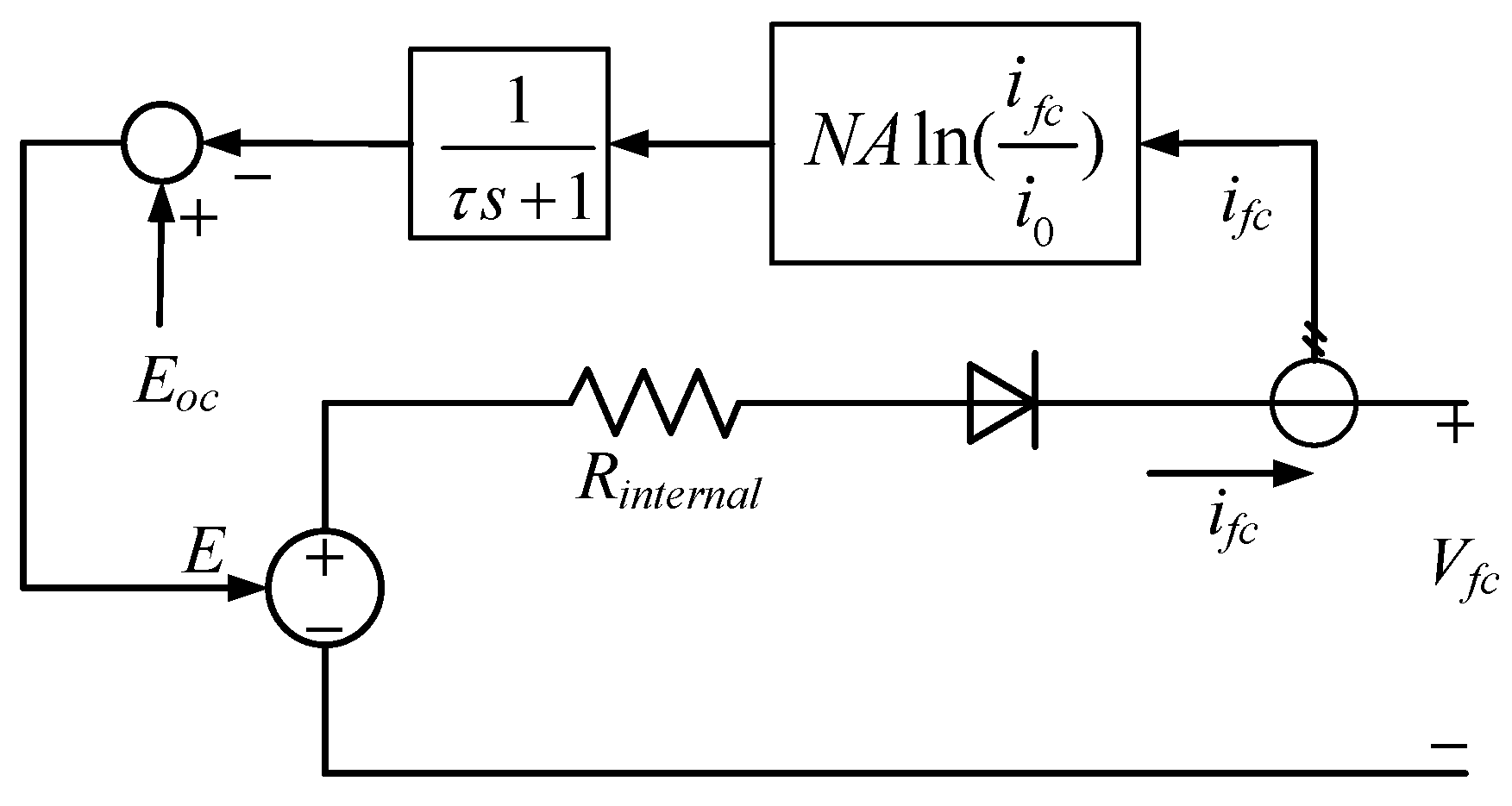
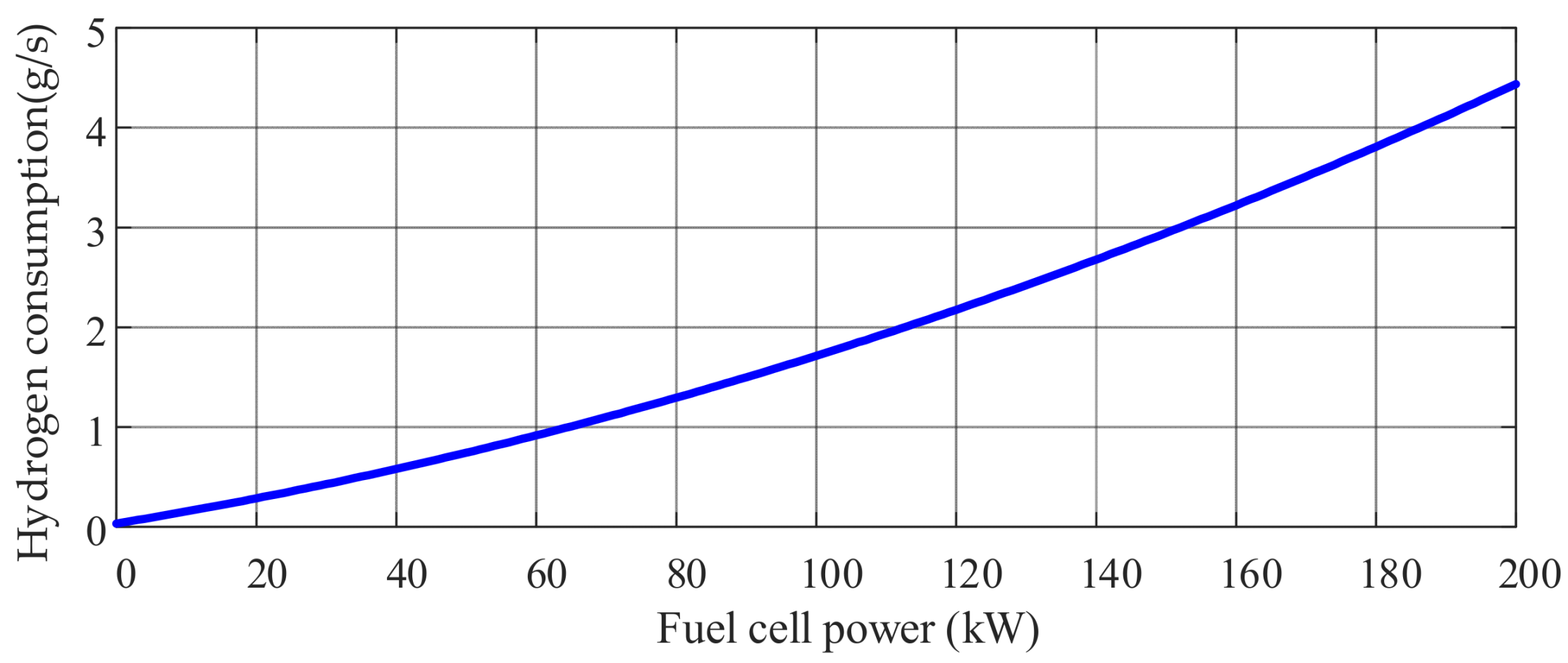
2.1.1. Fuel Cell Modeling

The fuel cell model constructed in this paper uses the fuel cell module (Fuel Cell Stack) provided by MATLAB R2021b This module is widely used. Users only need to provide the rated operating point, open circuit voltage, and maximum operating point of the fuel cell to simulate the operating characteristics of the fuel cell. This module is built based on the battery stack equivalent circuit, as shown in Figure 2.
Where Eoc and Vfc are the open circuit voltage and output voltage of the fuel cell, respectively, V; τ is the dynamic response time constant; N is the number of individual pieces of the fuel cell electric stack; A is the Tafel slope; ifc and i0 are the fuel cell output current and exchange current, respectively, A; and Rinternal is the equivalent internal resistance of the fuel cell, Ω.
The instantaneous hydrogen consumption rate of the fuel cell can be characterized as a quadratic function concerning the output power [22], as shown in Equation (1), and the corresponding instantaneous hydrogen consumption rate curve is shown in Figure 3.
C f c = a 1 P f c 2 + a 2 P f c + a 3
where Cfc is the instantaneous hydrogen consumption rate of the fuel cell, g/s; Pfc is the output power of the fuel cell, kW; a1, a2, and a3 are constants.

2.1.2. Lithium Battery Models

The paper uses an RINT model for battery modeling [23], which accounts for the internal resistance of lithium battery charging and discharging and the open-circuit voltage.
The structure is simple and conducive to deriving the efficiency characteristics of lithium batteries. Its topology is shown in Figure 4.
Where Uocv is the battery open-circuit voltage and Ubus is the bus voltage, V.
According to the RINT model, the open-circuit voltage of the battery pack Uocv, the internal resistance of the battery R, and the output power Pbat together determine the battery pack current Ibat, which is calculated as Equation (2).
I b a t = U o c v ( U 2 o c v 4 R P b a t ) 2 R
The charging and discharging efficiency ηchg,ηdis of Li-ion batteries can be calculated from Equation (3). Thus, the charge/discharge efficiency curve of the lithium-ion battery can be calculated, as shown in Figure 5.
η chg = 2 / 1 + 1 4 R chg P bat / U ocv 2 η dis = 1 + 1 4 R dis P bat / U ocv 2 / 2
where Rchg is the charging internal resistance and Rdis the discharging internal resistance.
The instantaneous equivalent hydrogen consumption of a lithium battery is the equivalent conversion of the instantaneous electrical energy output absorbed by the lithium battery into the corresponding hydrogen consumption [24]. The formula is shown in Equation (4).
C bat   = P bat   C FC _ a v g η dis   η chg _ avg   P FC _ avg   P bat   0 P bat   η chg   η d i s _ avg   C FC _ a v g P FC _ a v g P bat   < 0
where Cbat is the instantaneous equivalent hydrogen consumption of the lithium battery, g/s; CFc_avg is the average instantaneous hydrogen consumption of the fuel cell, g; ηdis_avg is the average discharge efficiency of the lithium battery; ηchg_avg is the average charging efficiency of the lithium battery; and PFC_avg is the average output power of the fuel cell, kW.

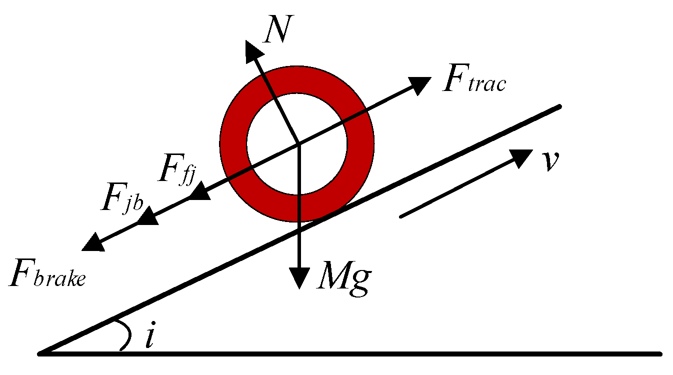
2.2. Dynamic Modeling of Shunting Locomotives

The actual technical parameters and operating conditions of a locomotive are selected to verify the feasibility of the parameter matching and energy management method of the fuel cell hybrid locomotive proposed in this paper, and the basic parameters of the locomotive are shown in Table 1. The vehicle dynamics model is shown in Figure 6.
Figure 6. Vehicle dynamics modeling.
Electronics 13 03599 g006
Where Ftrac is the traction force; Ffj is the additional resistance; Fjb is the basic running resistance; Fbrake is the braking force; Mg is the total gravitational force on the locomotive; N is the ground support force on the locomotive; i is the number of ramp kilometers; and v is the train operating speed.
Table 1. Basic vehicle parameters.
ParameterValue
Gauge1435 mm
AxialC0–C0
Maximum operating speed100 km/h
Axle weight25 t
Maximum starting tractive effort560 kN
Maximum electric braking power300 kN
Auxiliary system power100 kW
Transmission efficiency0.98
Inverter efficiency0.98
DC/DC efficiency0.95

2.2.1. Locomotive Traction Braking Characteristics

To ensure that the locomotive has sufficient traction and braking force, the maximum starting traction force of the locomotive is 560 kN, and the maximum braking force of the locomotive electric brake is 300 kN due to the viscous limitation. The traction and braking characteristics of the locomotive are shown in Figure 7.

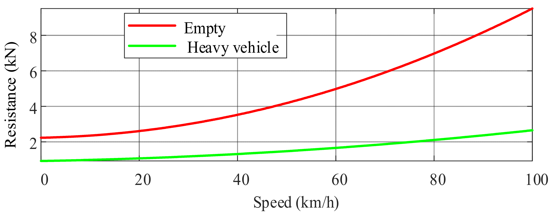
2.2.2. Locomotive Operating Resistance

The resistance of the vehicle in the process of operation can be divided into two aspects according to the reasons for the basic operational resistance and additional resistance of the line. The basic operating resistance Fjb is the resistance that always exists when the train is starting and running, which can be empirically expressed as a quadratic polynomial with the train speed as the independent variable. The basic operating resistance curve of a vehicle is shown in Figure 8.
F j b = w 0 m g / 1000
w 0 = A w + B w v + C w v 2
where w0 is the train unit’s basic running resistance; v is the train’s operating speed; and Aw, Bw, and Cw are the drag coefficients.
The additional resistance is connected to the line conditions. It includes slope additional resistance, curve additional resistance, and tunnel additional resistance. Due to the limited line data, the tunnel’s additional resistance is not considered in this paper. The formula for additional resistance Ffj is shown in Equation (7).
F f j = m g × ( w i + w r ) / 1000
The formulas for additional resistance wi per unit of the ramp and additional resistance wr per unit of the curve are shown in Equations (8) and (9).
w i = i ( x )
w r = 600 R ( x )
where i(x) is the kilo fraction of the ramp at mileage x, and r(x) is the radius of the curve at mileage x.

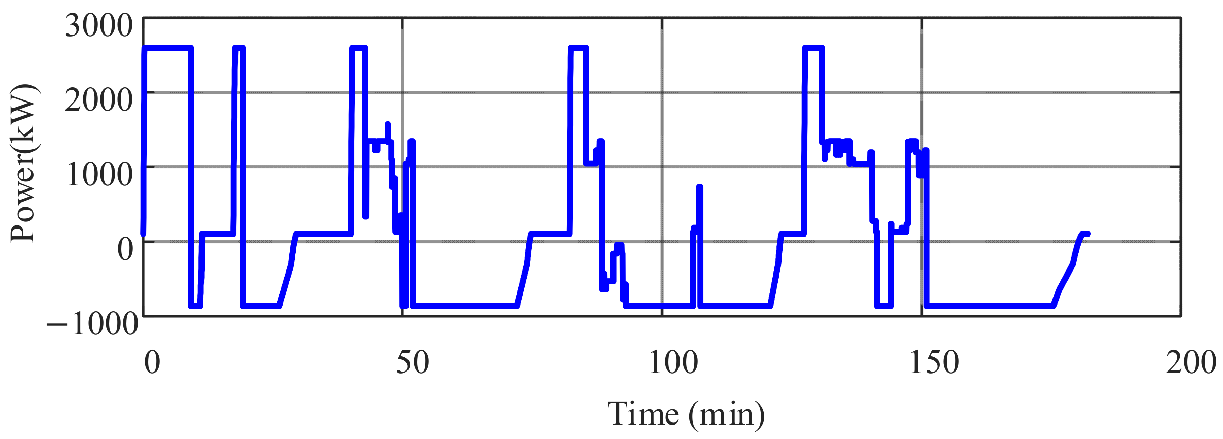
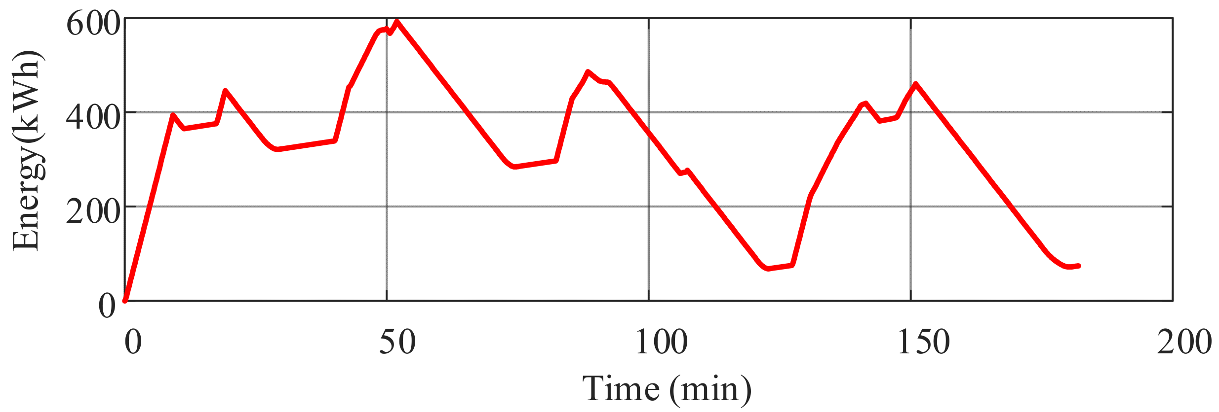
2.3. Train Operating Conditions

Based on the traction braking characteristic curve and running resistance of the vehicle, combined with the line data of a railroad line with a length of about 128 km for traction calculations, the demand power, demand energy consumption, and operating conditions of the vehicle are finally obtained, as shown in Figure 9, Figure 10 and Figure 11.
Before the optimization of parameter configuration, the initial parameter configuration of the project party is two sets of fuel cells, the number of lithium batteries in series is 672, and the number of parallel connections is 12. At the same time, the main technical parameters of the fuel cells and lithium batteries of the single unit are given, as shown in Table 2 and Table 3.

3. Optimization of the Parameter Configuration of the FCHPS

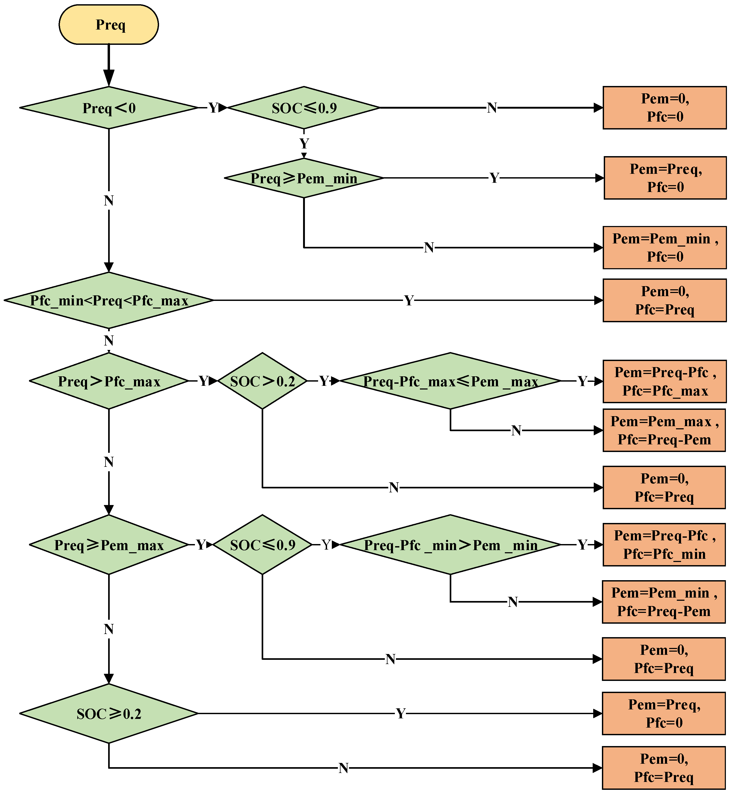
3.1. Rule-Based Energy Management Strategies

Before configuring the parameters of the FCHPS, it is first necessary to determine the energy management strategy (EMS) of the whole vehicle. The essence of the EMS is to reasonably allocate energy according to the respective characteristics of each energy source under the premise of satisfying the load demand, which can effectively improve the overall performance of the FCHPS. In this paper, a rule-based EMS is used to ensure real-time power allocation. Rule-based EMS relies on pre-defined rules to make fast and straightforward energy allocation decisions to ensure the efficient operation of FCHPS in real time. This approach differs from other types of energy management strategies, such as model predictive control (MPC) or fuzzy logic control, which typically involve more complex algorithms and require more computing resources. Therefore, this paper decides to use rule-based EMS to verify the rationality and effectiveness of the FCHPS parameter configuration optimization results. The EMS control rules formulated in this paper are shown in Table 4.
The resulting energy management control strategy is shown in Figure 12. The fuel cell should be operated in the high-efficiency zone as much as possible, while the battery should meet the remaining power demand as much as possible when the power is sufficient. When the remaining power exceeds the maximum discharge power of the battery, the output power of the fuel cell should be adjusted to meet the demand under the premise of ensuring that the battery operates normally at the maximum discharge power. In addition, the battery should absorb the excess power or recover braking energy as much as possible.
Where Preq is the demand power; Pfc is the fuel cell output power; Pfc_max and Pfc_min are the maximum and minimum efficient output power of the fuel cell; Pem is the battery output power; and Pem_min and Pem_max are the maximum charging and discharging power of the battery.

3.2. Multi-Objective Configuration Optimization Model

The efficient operation of an FCHPS relies on a reasonable matching of powertrain parameters and a good control strategy [25]. Optimizing the configuration parameters of a dynamical system that is, optimizing the relevant parameters to make multiple objective functions as optimal as possible simultaneously in the feasible region, provided that the constraints are satisfied. Therefore, FCHPS configuration optimization is a typical multi-objective optimization problem. In this paper, the system economy model and lightweight model are constructed with the optimization objectives of reducing the weight of FCHPS and increasing the system operation economy.

3.2.1. Economic Modeling

FCHPS economics modeling refers to the life of the vehicle as a calculation cycle and calculates the initial acquisition cost of the power source, the replacement cost, and the energy consumption cost included in the total cycle.
(1)
Initial acquisition costs
The total initial acquisition cost of the FCHPS consists of the initial acquisition cost of the power source and the initial acquisition cost of the corresponding power converter, which is calculated as shown in Equation (10). Among them, the initial acquisition cost of the power source consists of the initial acquisition cost of the fuel cell and the initial acquisition cost of the lithium battery, which are calculated as shown in Equations (11) and (12), respectively. The initial acquisition cost of the converter consists of the initial acquisition cost of the Boost converter and the initial acquisition cost of the bi-directional DC/DC power converter, which are calculated as shown in Equations (13) and (14), respectively.
C I = C f c _ i + C b a t _ i + C d c _ i + C d c d c _ i
C f c _ i = C f c _ u n i t × P f c × n f c
C b a t _ i = C b a t _ u n i t × U b a t _ u n i t × m b a t × Q b a t _ u n i t × n b a t / 1000
C d c _ i = C d c _ u n i t × P d c _ max
C d c d c _ i = C d c / d c _ u n i t × P d c / d c _ m a x
where CI is the total initial acquisition cost, 104CNY; Cfi_i, Cbat_i, Cdc_i, and Cdcdc_i are the initial acquisition costs of the fuel cell, lithium battery, Boost converter, and bidirectional DC/DC converter, respectively, 104CNY; Cfc_unit is the unit price of the power of the fuel cell, 104CNY/kW; Pfc is the power of a single fuel cell, kW; and nfc is the number of configured fuel cells. Cbat_unit is the unit price of lithium battery, 104CNY/kWh; Ubat_unit is the voltage of a single battery, V; Qbat_unit is the capacity of a single battery, Ah; mbat is the number of battery packs in series; and nbat is the number of battery packs in parallel. Cdc_unit is the unit price of the Boost converter, 104CNY/kW; and Pdc_max is the maximum power of the Boost converter, kW; Cdc/dc_unit is the unit price of the bidirectional DC/DC converter, 104CNY/kW; and Pdc/dc_max is the maximum power of bidirectional DC/DC converter, kW.
(2)
Replacement costs
The replacement cost of the FCHPS consists of the fuel cell replacement cost and the storage battery replacement cost, which is calculated as shown in Equation (15).
C R = C f c _ r + C b a t _ r
where CR is the total replacement cost, 104CNY; and Cfc_r and Cbat_r are the replacement costs for fuel cells and lithium batteries, respectively, 104CNY.
  • 1)
    Fuel cell replacement costs
In this paper, a calculation method for fuel cell life is adopted [26,27]. The method first defines the typical operating conditions of an onboard fuel cell system, then determines the effects of various operating conditions on the performance degradation of the fuel cell, and finally obtains the performance degradation value of the fuel cell by accumulating the number of times that various typical operating conditions occur under the whole operating conditions.
The performance of an onboard fuel cell is primarily affected by four typical operating conditions: start–stop, idle, high speed, and variable load. PEI P. et al. [26] conducted long-term cyclic tests, decoupling various influencing factors to analyze the performance degradation of the fuel cell under each operating condition. Among these, degradation due to variable load conditions accounted for the largest proportion, approximately 56.6%, followed by start–stop conditions at around 33%. Degradation due to idling and high speed accounted for about 4.7% and 5.8%, respectively.
The voltage decay rate is the main index to evaluate the performance degradation of fuel cells. Based on the working condition information, the working load spectrum of the fuel cell can be extracted, to establish the objective function related to the life of the fuel cell, which is shown in Equation (16). Based on this objective function, the replacement cost of the fuel cell can be calculated as shown in Equation (17).
L i f e f c = Δ P k p k 1 n 1 + k 2 t 1 + k 3 n 2 + k 4 t 2
C f c _ r = C f c _ i × c e i l ( T z h o u q i L i f e f c 1 )
where Lifefc is the available life of the fuel cell, years; ∆P is the degradation of fuel cell performance from the beginning to the end of the life; kp is the environmental acceleration coefficient; k1, k2, k3, and k4 are the degradation coefficients of fuel cell performance under start–stop, idling, variable load, and heavy load conditions; n1, t1, n2, and t2 are the number of starts and stops, idling time, number of variable loads, and heavy load time; and Tzhouqi is the vehicle operating cycle, years.
  • 2)
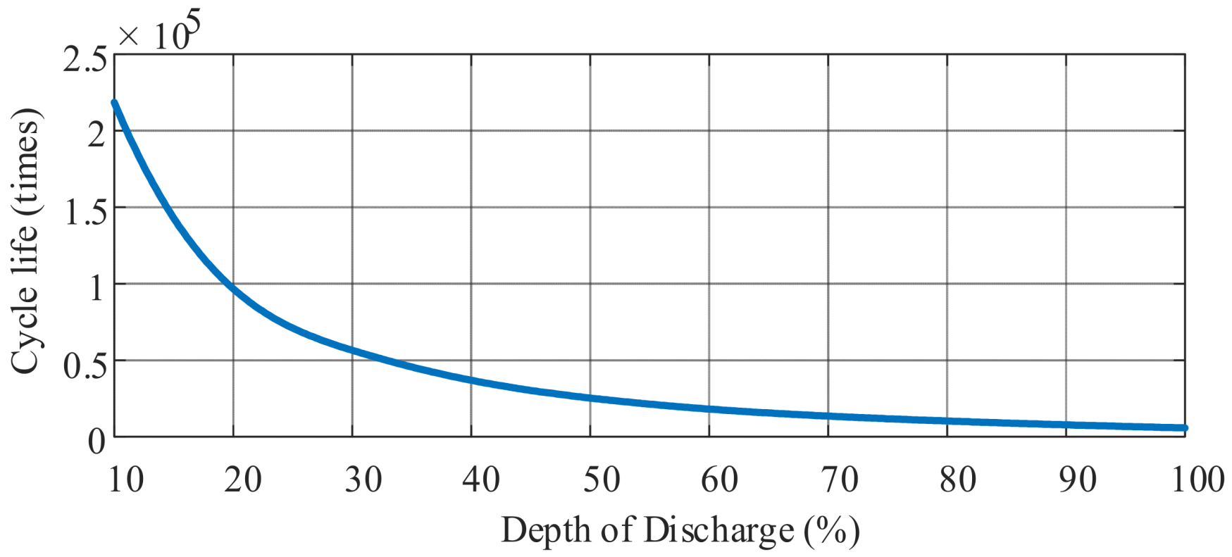
    Energy storage battery replacement costs
The cycle life of lithium batteries is affected by many factors, such as the number of charge/discharge times, the depth of discharge (DOD), and the temperature. In order to simplify the analysis, this paper only considers the effect of DOD and the number of charge/discharge times on the cycle life of lithium batteries [28]. Figure 13 shows the relationship curve between the DOD and the number of cycle lives provided by the project. In this paper, firstly, the depth of discharge of the lithium battery is calculated by the rain flow counting method [29]. The number of cycles of the battery in different DOD intervals is calculated, and then the relationship curve between DOD and the number of cycle life is referred to, so as to calculate the service life of the battery pack, which is calculated as shown in Equation (18), and finally, the replacement cost of lithium battery is calculated by Equation (19) [30].
L i f e b a t = min [ L i f e b a t , r l , 1 j = 1 10 N b a t , j / C F b a t , j ]
C b a t _ r = C b a t _ u n i t × E b a t × c e i l ( T z h o u q i L i f e b a t 1 )
where Lifebat is the cycle life of the battery, years; Lifebat,rl is the calendar life of the battery, years; Nbat,j is the number of cycles of the battery in one year calculated for different DOD intervals; CFbat,j is the number of cycle life of the battery corresponding to different DOD intervals; and Ebat is the total energy of the battery pack, kWh.
(3)
Energy costs
The energy cost of vehicle operation is decided by the cost of the hydrogen consumed. The formulas for the instantaneous hydrogen consumption of the fuel cell and the instantaneous equivalent hydrogen consumption of the Li-ion battery have been given in Section 2.1. Based on this, the total instantaneous hydrogen consumption of the system can be calculated by Equation (20). By using Equation (21), the total hydrogen consumption of the system can be calculated to obtain the energy cost of the FCHPS, which is calculated as in Equation (22).
H c = C f c + k C b a t
W H 2 = 0 t cyc H c ( t ) d t / 1000
C H 2 = C H 2 _ k g × W H 2 / 10 , 000
where Hc is the total instantaneous hydrogen consumption of the system, g/s; k is the correction coefficient; WH2 is the total hydrogen consumption of the system in kg; tcyc is the operating time of the fuel cell hybrid system, s; CH2 is the cost of energy consumption, 104CNY; and CH2_kg is the unit price of hydrogen, CNY/kg.
From the above, the economy of the FCHPS is modeled as:
C = C I + C R + C H 2
where C is the total cost, 104CNY.

3.2.2. Lightweight Modelling

The FCHPS studied in this paper is an onboard system. All power sources and auxiliary equipment need to be placed in the vehicle, and to ensure that the total weight of the vehicle does not exceed the specified limits, the weight of the FCHPS must be limited and optimized. Compared with fuel cells and batteries, power converters are very light and have little impact on the overall optimization results during parameter configuration. Therefore, this paper only focuses on the weight optimization of the fuel cell stack and the battery stack. Based on this, the lightweight model of the FCHPS consists of the weights of the fuel cell pack and the battery pack, with their respective calculation formulas provided in Equations (24) and (25).
M a s s f c = M a s s f c _ u n i t × n f c
M a s s b a t = M a s s b a t _ u n i t × m b a t × n b a t
where Massfc and Massbat are the total weights of the fuel cell pack and the lithium battery pack, respectively, kg; Massfc_unit and Massbat_unit are the weights of the single fuel cell and the lithium battery, respectively, kg.
Thus, the lightweight model of the FCHPS can be obtained, as shown in Equation (26).
M = M a s s f c + M a s s b a t
where M is the total mass of the FCHPS, kg.

3.3. Overall Optimization Objective Function and Constraints

Section 3.1 identifies two optimization objectives: economy C and lightweight M. To achieve a reasonable balance among multiple optimization objectives, this paper introduces a weighting coefficient wi to characterize the importance of each optimization objective. The weight coefficients are set based on the priorities of specific application scenarios, with higher weights indicating higher priorities for the corresponding objectives. This approach allows decision-makers to flexibly adjust weight coefficients according to specific needs, thereby obtaining the optimal configuration that meets different priorities.
The overall optimization objective function of the FCHPS configuration optimization model is shown in Equation (27).
J = w 1 · C C m a x + w 2 · M M m a x
where Cmax and Mmax are the maximum values of each optimization objective, which was obtained from the initial configuration scheme. w1 and w2 are the weight coefficients corresponding to the economy objective and the lightweight objective, respectively, and w1 + w2 = 1.
In the optimal design of the parameter configuration of the FCHPS, in addition to considering the whole optimization objective function, it is also necessary to consider the constraints shown in Equation (28).
P f c _ min P f c P f c _ max P b a t _ min P b a t P b a t _ max S O C b a t _ s t a r t = S O C b a t _ e n d S O C b a t _ min S O C b a t S O C b a t _ max n f c × m c e l l _ f c + m b a t × n b a t × m c e l l M max n f c × v c e l l _ f c + m b a t × n b a t × v c e l l V max U b a t _ max U b u s _ r a t e d U f c _ max U b u s _ r a t e d U b a t _ min U b a t U b a t _ max
where Pfc_max and Pfc_min are the maximum and minimum output power of the fuel cell; Pbat_min and Pbat_max are the maximum charging and discharging power of the lithium battery; and SOCbat_start and SOCbat_end are the start and end state of charge of the battery. SOCbat is the state of charge of the battery; SOCbat_max and SOCbat_min are the upper and lower limits of the battery charge state; mcell is the mass of the Li-ion battery unit; Vcell is the volume of the Li-ion battery unit; mcell_fc is the mass of fuel cell unit; Vcell_fc is the volume of fuel cell unit; Ubus_rated is the rated DC bus voltage; Ubat_max, Ubat_min are the upper and lower limits of the output voltage of the battery; and Ufc_max is the maximum output voltage of the fuel cell.

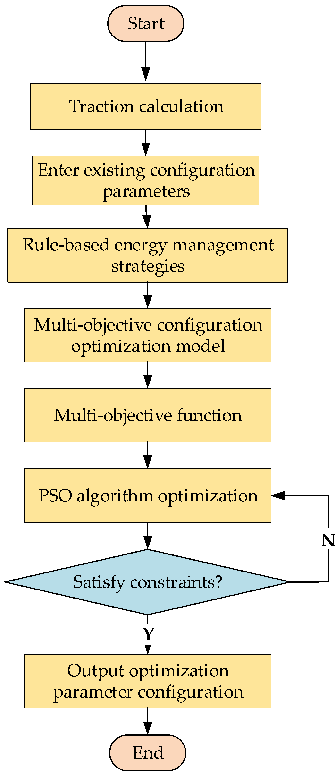
4. Optimization of Configuration Parameters Based on PSO

In this paper, the number of fuel cell sets nfc, the number of a series connection of batteries mbat, and the number of parallel connections of batteries nbat are set as the optimization parameters. The value ranges of the three optimization parameters are shown in Table 5.

4.1. Implementation of Optimization Algorithms

The particle swarm optimization (PSO) algorithm has become a powerful tool for solving various complex optimization problems due to its unique optimization mechanism and efficient global search capability. Compared to other optimization methods, such as the genetic algorithm (GA) and the simulated annealing algorithm (SA), the PSO algorithm features a simpler algorithmic structure, requires less parameter tuning, and exhibits faster convergence [31]. In addition, the PSO algorithm outperforms other algorithms in similar applications. Pei, H et al. [29] pointed out that among the three optimization algorithms, PSO is particularly effective in finding the best solution because it has a stronger ability to escape from the local optimal state and is more likely to find the global optimal solution than the other two algorithms. This further enhances the applicability of the PSO algorithm as an optimization method in this paper. The basic flow of optimization of the PSO algorithm is shown in Figure 14. The table of running parameters is shown in Table 6.
The flowchart for optimizing the parameter configuration of the FCHPS is shown in Figure 15. Firstly, the traction calculation is carried out to obtain the demand power and demand energy of the vehicle. Next, the existing configuration parameters are input and the EMS designed in the previous section is used to reasonably allocate the power output of the hydrogen fuel cell group and the lithium titanate battery group. Based on this, the target values of the system economy target and lightweight target under the existing configuration are calculated, as well as the value of the overall multi-objective function. Finally, the PSO algorithm is used for optimization, and certain constraints are taken into account to obtain the optimal configuration through continuous optimization.

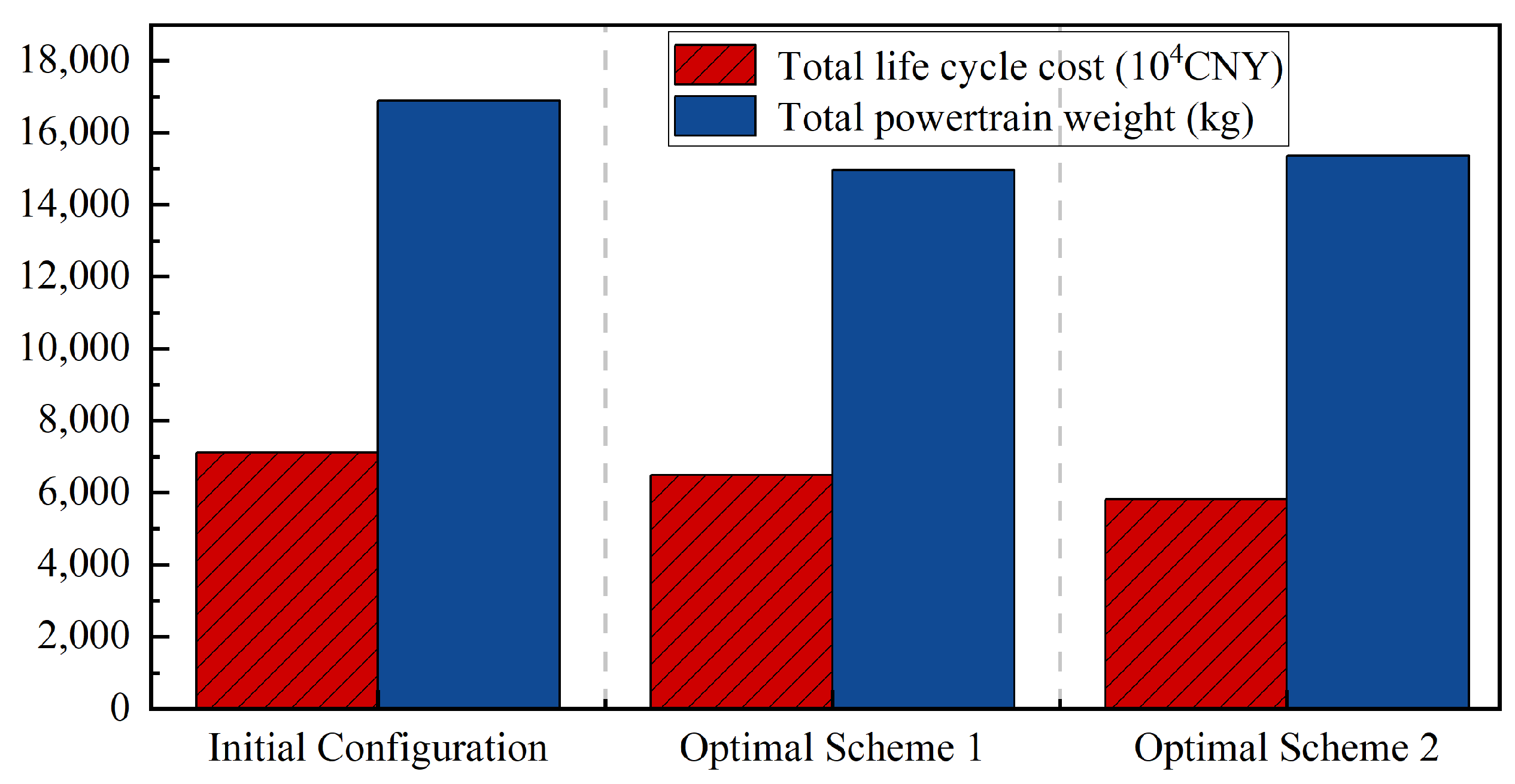
4.2. Analysis of Optimization Results

When designing weight coefficients, decision-makers can make adjustments based on actual needs and priorities. For example, in some scenarios, the economy may be the main focus, while in others, lightweightness might be more critical. Therefore, this paper lists two different sets of weight coefficients: the first set prioritizes lightweightness over economy, while the second set emphasizes economy with less focus on lightweightness. By adjusting these coefficients, the emphasis of each objective can be changed during the optimization process, thereby obtaining multiple different optimal solutions. Then, by using the PSO algorithm, the respective optimal configurations can be found under different weight combinations. Figure 16 and Figure 17 illustrate the optimization results for the two sets of weighting coefficients listed in Table 7.
From the results, it can be concluded that for the three optimization variables under the first set of weight coefficients of 0.8 and 0.2, the optimization results, i.e., the number of series and parallel connections of lithium titanate batteries and the number of hydrogen fuel cells are 534.493, 12.8301, and 1.47243, respectively. Rounded upwards, the number of series connections of lithium titanate batteries is 535, the number of parallel connections is 13, and the number of hydrogen fuel cells is 2. Therefore, the configuration optimization scheme 1 can be expressed as 535S/13P/2, and similarly, the optimization results for the three optimization variables under the second set of weight coefficients of 0.2 and 0.8 can be expressed as 614S/13P/1. Based on the above optimization results, the economic costs and total weights under the existing configuration of the fuel cell hybrid system and the two optimized configurations are calculated separately, as shown in Table 8. The optimization results are also compared, and the results are shown in Figure 18.
According to the results, compared to the initial configuration, the optimized economic cost is reduced by 8.76% and 18.05%, respectively, and the system weight is reduced by 11.47% and 9.13%, respectively. The two optimized configurations with different sets of weight coefficients outperform the initial configuration in terms of economy and total weight and successfully achieve the goals of reducing the economic cost and reducing the weight of the system. It shows that the proposed optimization method can effectively improve the overall performance of FCHPS. Specifically, among the two optimized configuration schemes, optimal scheme 1 has the lightest weight, but the economic cost is relatively high, which verifies the need to pay more attention to the system’s lightweight when setting the weight coefficient. On the contrary, the economic cost of optimal scheme 2 is the lowest, but the weight is relatively high, indicating that when the weight coefficient focuses more on reducing the economic cost, the optimization result will prioritize minimizing the cost, but may increase the weight of the system. This verifies that it is feasible and effective to use the particle swarm optimization algorithm to solve the FCHPS multi-objective optimization problem based on different weight coefficients. By adjusting the weighting coefficients, different configurations focusing on cost and weight can be obtained, which provides decision-makers with a flexible basis for choosing the most suitable optimization scheme based on actual needs.

5. Conclusions

In this paper, the demanded power and demanded energy of the vehicle were derived by traction calculation, and a multi-constraint and multi-objective parameter configuration optimization model was constructed on this basis. Subsequently, the PSO algorithm was used to find the optimal solution for the control variables, and the power system parameter configuration scheme with optimization effect was finally obtained. The main research results are as follows.
(1)
A multi-objective optimization function covering the economic cost and total system weight over the whole life cycle of the vehicle is constructed, and the economy model and lightweight model are established separately. These models can effectively assess the rationality of the configuration of the FCHPS in practical applications and lay a solid foundation for the subsequent parameter optimization.
(2)
A method for optimizing a multi-objective function using a PSO algorithm is proposed. By optimally solving two sets of different weight coefficients representing different optimization objectives and comparing the optimization results with the initial configuration, the results of the study show that the optimized economic costs are reduced by 8.76% and 18.05%, while the system weights are reduced by 11.47% and 9.13%, respectively, compared with the initial configuration. This result shows that the optimization methodology can significantly reduce the economic cost over the whole life cycle of the FCHPS and effectively reduce the weight of the system, achieving the desired optimization goal.
(3)
The multi-objective optimization method proposed in this paper shows certain advantages. The PSO algorithm is able to globally optimize different sets of weighting coefficients, and in the study of multi-objective configuration optimization of FCHPS, multiple optimal solutions can be obtained by setting different weighting coefficients. Although only one optimal solution can be obtained in each optimization process, more different optimal configurations can be obtained by adjusting the weighting coefficients, thus providing more flexibility and choice space for FCHPS design.
Overall, through the construction of a multi-objective optimization model and the application of the PSO algorithm, this study not only verifies the effectiveness of the optimization method but also provides a practical guidance strategy for the configuration optimization of FCHPS. This research result provides an important reference value for the design and optimization of future FCHPS.
Although this study has achieved positive results in the optimization of parameter configurations of FCHPS, there are still some shortcomings. Firstly, the optimization model needs to be strengthened in considering the actual working conditions and dynamic factors; secondly, the PSO algorithm has limitations in convergence speed and avoids falling into local optimum in multi-objective optimization. Future research can further improve the optimization effect and practical applicability by introducing complex working condition data and adaptive optimization algorithms.

Author Contributions

Conceptualization, S.L. and C.X.; methodology, S.L.; software, S.L. and H.P.; validation, S.L., Y.Z. and H.P.; formal analysis, S.L. and Y.Z.; investigation, S.L.; resources, S.L., Y.Z. and H.P.; data curation, S.L.; writing—original draft preparation, S.L.; writing—review and editing, C.X.; visualization, S.L.; supervision, K.D., N.Y. and Y.M.; project administration, K.D., N.Y. and Y.M.; funding acquisition, C.X. All authors have read and agreed to the published version of the manuscript.

Funding

This research was funded by the Science and Technology Research and Development Plan of the China Railway Group Co., Ltd., grant number N2023J064.

Data Availability Statement

Data are contained within the article.

Conflicts of Interest

Authors Kan Dong, Ning Yang and Yingtao Ma are employed by the companies Locomotive and Car Research Institute, China Academy of Railway Sciences Co., Ltd., and Beijing Zongheng Electro-Mechanical Technology Co., Ltd. The remaining authors declare that the research was conducted in the absence of any commercial or financial relationships that could be construed as a potential conflict of interest.

References

  1. Liu, H.; Chen, J.; Hissel, D.; Lu, J.; Hou, M.; Shao, Z. Prognostics methods and degradation indexes of proton exchange membrane fuel cells: A review. Renew. Sustain. Energy Rev. 2020, 123, 109721. [Google Scholar] [CrossRef]
  2. Rokni, M. Performance comparison on repowering of a steam power plant with gas turbines and solid oxide fuel cells. Energies 2016, 9, 399. [Google Scholar] [CrossRef]
  3. Yaghoubi, E.; Yaghoubi, E.; Khamees, A.; Razmi, D.; Lu, T. A systematic review and meta-analysis of machine learning, deep learning, and ensemble learning approaches in predicting EV charging behavior. Eng. Appl. Artif. Intell. 2024, 135, 108789. [Google Scholar] [CrossRef]
  4. Li, Q.; Yang, H.; Han, Y.; Li, M.; Chen, W. A state machine strategy based on droop control for an energy management system of PEMFC-battery-supercapacitor hybrid tramway. Int. J. Hydrogen Energy 2016, 41, 16148–16159. [Google Scholar] [CrossRef]
  5. Fernandez, L.M.; Garcia, P.; Garcia, C.A.; Jurado, F. Hybrid electric system based on fuel cell and battery and integrating a single dc/dc converter for a tramway. Energy Convers. Manag. 2011, 52, 2183–2192. [Google Scholar] [CrossRef]
  6. Council, H. Hydrogen Scaling Up: A Sustainable Pathway for the Global Energy Transition; Hydrogen Council: Brussels, Belgium, 2017. [Google Scholar]
  7. Calvert, C.; Allan, J.; Amor, P.; Hillmansen, S.; Roberts, C.; Weston, P. Concept development and testing of the UK’s first hydrogen-hybrid train (HydroFLEX). Railw. Eng. Sci. 2021, 29, 248–257. [Google Scholar] [CrossRef]
  8. Mustafa, M.Y.; Al-Mahadin, A.; Calay, R.K. Fuel cell technology application for Dubai rail systems. In Proceedings of the 2018 Advances in Science and Engineering Technology International Conferences (ASET), Dubai, United Arab Emirates, 6 February–5 April 2018; pp. 1–7. [Google Scholar]
  9. Palmer, C. Hydrogen-powered trains start to roll. Engineering 2022, 11, 9–11. [Google Scholar] [CrossRef]
  10. Ozawa, A.; Kudoh, Y.; Murata, A.; Honda, T.; Saita, I.; Takagi, H. Hydrogen in low-carbon energy systems in Japan by 2050: The uncertainties of technology development and implementation. Int. J. Hydrogen Energy 2018, 43, 18083–18094. [Google Scholar] [CrossRef]
  11. Fotopoulou, M.; Pediaditis, P.; Skopetou, N.; Rakopoulos, D.; Christopoulos, S.; Kartalidis, A. A Review of the Energy Storage Systems of Non-Interconnected European Islands. Sustainability 2024, 16, 1572. [Google Scholar] [CrossRef]
  12. Al Amerl, A.; Oukkacha, I.; Camara, M.B.; Dakyo, B. Real-time control strategy of fuel cell and battery system for electric hybrid boat application. Sustainability 2021, 13, 8693. [Google Scholar] [CrossRef]
  13. Zhang, Y.; Diao, L.; Xu, C.; Zhang, J.; Wu, Q.; Pei, H.; Huang, L.; Li, X.; Qi, Y. An optimization of new energy hybrid configuration parameters based on GA method. J. Mar. Sci. Eng. 2022, 10, 1747. [Google Scholar] [CrossRef]
  14. Wu, X.; Hu, X.; Yin, X.; Li, L.; Zeng, Z.; Pickert, V. Convex programming energy management and components sizing of a plug-in fuel cell urban logistics vehicle. J. Power Sources 2019, 423, 358–366. [Google Scholar] [CrossRef]
  15. Zhang, G.; Chen, W.; Li, Q. Modeling, optimization and control of a FC/battery hybrid locomotive based on ADVISOR. Int. J. Hydrogen Energy 2017, 42, 18568–18583. [Google Scholar] [CrossRef]
  16. Hu, Z.; Li, J.; Xu, L.; Song, Z.; Fang, C.; Ouyang, M.; Dou, G.; Kou, G. Multi-objective energy management optimization and parameter sizing for proton exchange membrane hybrid fuel cell vehicles. Energy Convers. Manag. 2016, 129, 108–121. [Google Scholar] [CrossRef]
  17. Lü, X.; Wu, Y.; Lian, J.; Zhang, Y.; Chen, C.; Wang, P.; Meng, L. Energy management of hybrid electric vehicles: A review of energy optimization of fuel cell hybrid power system based on genetic algorithm. Energy Convers. Manag. 2020, 205, 112474. [Google Scholar] [CrossRef]
  18. Hu, X.; Murgovski, N.; Johannesson, L.M.; Egardt, B. Optimal dimensioning and power management of a fuel cell/battery hybrid bus via convex programming. IEEE/ASME Trans. Mechatron. 2014, 20, 457–468. [Google Scholar] [CrossRef]
  19. De Almeida, S.C.; Kruczan, R. Effects of drivetrain hybridization on fuel economy, performance and costs of a fuel cell hybrid electric vehicle. Int. J. Hydrogen Energy 2021, 46, 39404–39414. [Google Scholar] [CrossRef]
  20. Hu, H.; Yuan, W.-W.; Su, M.; Ou, K. Optimizing fuel economy and durability of hybrid fuel cell electric vehicles using deep reinforcement learning-based energy management systems. Energy Convers. Manag. 2023, 291, 117288. [Google Scholar] [CrossRef]
  21. Huynh, T.; Pham, A.T.; Lee, J.; Nguyen-Xuan, H. Optimal parametric design of fuel cell hybrid electric vehicles by balancing composite motion optimization. Int. J. Precis. Eng. Manuf.-Green Technol. 2024, 11, 123–143. [Google Scholar] [CrossRef]
  22. Meng, X.; Li, Q.; Zhang, G.; Chen, W. Efficient multidimensional dynamic programming-based energy management strategy for global composite operating cost minimization for fuel cell trams. IEEE Trans. Transp. Electrif. 2021, 8, 1807–1818. [Google Scholar] [CrossRef]
  23. Wu, M.; Qin, L.; Wu, G. State of power estimation of power lithium-ion battery based on an equivalent circuit model. J. Energy Storage 2022, 51, 104538. [Google Scholar] [CrossRef]
  24. Xu, L.; Li, J.; Hua, J.; Li, X.; Ouyang, M. Optimal vehicle control strategy of a fuel cell/battery hybrid city bus. Int. J. Hydrogen Energy 2009, 34, 7323–7333. [Google Scholar] [CrossRef]
  25. Zhao, H.; Xu, J.; Xu, K.; Sun, J.; Wang, Y. Optimal allocation method of source and storage capacity of PV-Hydrogen zero carbon emission microgrid considering the usage cost of energy storage equipment. Energies 2022, 15, 4916. [Google Scholar] [CrossRef]
  26. Pei, P.; Chang, Q.; Tang, T. A quick evaluating method for automotive fuel cell lifetime. Int. J. Hydrogen Energy 2008, 33, 3829–3836. [Google Scholar] [CrossRef]
  27. Chen, H.; Pei, P.; Song, M. Lifetime prediction and the economic lifetime of proton exchange membrane fuel cells. Appl. Energy 2015, 142, 154–163. [Google Scholar] [CrossRef]
  28. Herrera, V.I.; Gaztañaga, H.; Milo, A.; Saez-de-Ibarra, A.; Etxeberria-Otadui, I.; Nieva, T. Optimal energy management and sizing of a battery--supercapacitor-based light rail vehicle with a multiobjective approach. IEEE Trans. Ind. Appl. 2016, 52, 3367–3377. [Google Scholar] [CrossRef]
  29. Pei, H.; Diao, L.; Jin, Z.; Xu, C.; Zhang, Y.; Fan, Y. A multi-objective optimal sizing scheme for hybrid traction power supply systems onboard shunting locomotive. Alex. Eng. J. 2023, 72, 399–414. [Google Scholar] [CrossRef]
  30. Herrera, V.; Milo, A.; Gaztañaga, H.; Etxeberria-Otadui, I.; Villarreal, I.; Camblong, H. Adaptive energy management strategy and optimal sizing applied on a battery-supercapacitor based tramway. Appl. Energy 2016, 169, 831–845. [Google Scholar] [CrossRef]
  31. Wang, D.; Tan, D.; Liu, L. Particle swarm optimization algorithm: An overview. Soft Comput. 2018, 22, 387–408. [Google Scholar] [CrossRef]
Figure 1. FCHPS topology.
Electronics 13 03599 g001
Figure 2. Equivalent circuit of fuel cell stack.
Electronics 13 03599 g002
Figure 3. Fuel cell instantaneous hydrogen consumption rate curve.
Electronics 13 03599 g003
Figure 4. RINT model of lithium battery.
Electronics 13 03599 g004
Figure 5. Lithium-ion battery charge/discharge efficiency curve.
Electronics 13 03599 g005
Figure 7. Vehicle traction braking characteristic curve. (a) Traction characteristic curve (b) Braking characteristic curve.
Electronics 13 03599 g007
Figure 8. Vehicle basic operating resistance curve.
Electronics 13 03599 g008
Figure 9. Demand load power curve.
Electronics 13 03599 g009
Figure 10. Demand load energy consumption curve.
Electronics 13 03599 g010
Figure 11. Velocity time curve.
Electronics 13 03599 g011
Figure 12. Energy management control strategy.
Electronics 13 03599 g012
Figure 13. Depth of Discharge Curve.
Electronics 13 03599 g013
Figure 14. Block diagram of PSO algorithm.
Electronics 13 03599 g014
Figure 15. Schematic diagram of PSO configuration optimization.
Electronics 13 03599 g015
Figure 16. PSO results for weighting coefficients of 0.8, 0.2.
Electronics 13 03599 g016
Figure 17. PSO results for weighting coefficients of 0.2, 0.8.
Electronics 13 03599 g017
Figure 18. Comparison of existing configuration and optimization results.
Electronics 13 03599 g018
Table 2. Main parameters of fuel cells.
ParameterValue
System output voltage rangeDC 450–750 V
Output power200 kW
Working environment temperature−30~40 °C
Working life≥10,000 h
Weight1400 kg
Dimensions3264 mm × 2600 mm × 830 mm
Table 3. Main parameters of lithium battery.
ParameterValue
Nominal capacity40 Ah
Nominal voltage2.35 V
Operating voltage range1.5 V–2.8 V
Operating temperature−25~55 °C
Dimension227 mm × 170 mm × 11.5 mm
Weight0.95 kg
Table 4. EMS development rules.
Rules and RegulationsFeature Description
Efficient fuel cell operationTry to keep the fuel cell operating in the high-efficiency zone to reduce the degradation of its performance by start–stop, load change, heavy load, no load, and so on.
Maximizing braking energy recoveryWhen the train decelerates, priority is given to absorbing braking energy with the power battery, and resistive braking and mechanical braking are used when the absorption capacity is exceeded.
Battery charge and discharge protectionSet the upper and lower limits of power battery charging and discharging to avoid high-power shock and ensure its safety and durability.
SOC maintenanceCharge the battery for peak power demand when the fuel cell is rich in power and the battery SOC is low.
Table 5. Parameters related to optimization variables.
Variable NameDescription of VariablesRange of Values
nfcNumber of fuel cell sets (groups)1~8
mbatNumber of batteries in series (pcs)511~745
nbatNumber of batteries in parallel (pcs)1~30
Table 6. PSO algorithm operating parameters.
ParameterDimensionMaximum Number of IterationsPopulation SizeAcceleration
Parameter
Value32000502
Table 7. Values of the two groups of weighting coefficients.
Weighting Factorw1w2
Group I0.80.2
Group II0.20.8
Table 8. Objective values for the existing and optimal configuration option.
Configuration SchemeInitial ConfigurationOptimal Scheme 1Optimal Scheme 2
Multi-objective function weight coefficients0.8, 0.20.2, 0.8
Lithium battery configuration (number of series-parallel connections)672S12P535S13P614S13P
Fuel cell configuration (sets)221
Total life cycle cost (104CNY)7110.476487.375827.34
Total FCHPS weight (kg)16,899.9014,960.8215,356.53
Disclaimer/Publisher’s Note: The statements, opinions and data contained in all publications are solely those of the individual author(s) and contributor(s) and not of MDPI and/or the editor(s). MDPI and/or the editor(s) disclaim responsibility for any injury to people or property resulting from any ideas, methods, instructions or products referred to in the content.

