Article

Cross-Channel Color Image Encryption Scheme Based on Discrete Memristive Coupled Neurons and DWT Compression

School of Information Science and Engineering, Dalian Polytechnic University, Dalian 116034, China
*
Authors to whom correspondence should be addressed.
Electronics 2024, 13(13), 2647; https://doi.org/10.3390/electronics13132647
Submission received: 17 June 2024 / Revised: 3 July 2024 / Accepted: 4 July 2024 / Published: 5 July 2024
(This article belongs to the Special Issue Recent Advances and Related Technologies in Neuromorphic Computing)

Abstract

:
To address the consumption and security of color images for transmission and storage, a cross-channel color image encryption scheme based on a discrete memristive coupled neuron model and DWT compression is designed in this article. Firstly, the dynamics of the discrete memristive coupled neuron system are analyzed and found to possess the hyperchaotic phenomenon, which provides sufficient security for the encryption scheme. Secondly, the color image processed by discrete wavelet transform (DWT) has a quarter of the previous capacity. Then, the color image is combined with a Hash function, and the resulting Hash sequence is given the initial value of the hyperchaotic system. Next, a particle swarm foraging algorithm (PSFA) is designed to better disrupt the correlation in the RGB channel. Finally, a complementary DNA coding rule is implemented for the further encryption of color images. Simulation results show that even with DWT lossy compression, the recovered image can be clearly seen. The performance analysis illustrates that under the hyperchaotic system, the proposed encryption algorithm brings higher security for color images.

1. Introduction

With the advent of the information age, digital images have played an increasingly important role in production and life. However, with the popularization of network communication, more and more image data are facing the serious challenge of security [1,2,3,4,5]. In this context, image encryption technology has become one of the critical means to protect image security. Encryption technology disrupts the structure and changes the content of an image [6,7,8,9,10]. Unauthorized users cannot recover the content and structure of the original image, thus protecting the image information [11,12,13,14,15,16].
In recent years, chaotic systems have been applied in the field of image encryption due to their properties such as high nonlinearity, sensitivity concerning initial conditions and pseudo-randomness [17,18,19,20,21,22]. These properties endow chaotic systems with good randomness and complexity, which can allow them to effectively resist various statistical attacks [23,24,25,26,27,28]. Meanwhile, various types of chaotic systems are fabricated, such as continuous systems [29,30,31,32,33,34,35,36,37,38], discrete systems [39,40,41,42,43] and fractional-order systems [44,45,46,47]. Gao et al. designed a hyperchaotic map and applied it in multi-image encryption, which saved a lot of time for the encryption algorithm [13]. Lai et al. presented a new 1D sine–cosine chaotic map for image encryption and applied randomized DNA encoding rules to encrypt images [48]. M. Naim et al. proposed a new chaotic satellite image encryption algorithm, which uses different filters for filtering and then the Fisher–Yates shuffle rule to disrupt the pixel order. Encryption using the block region approach was achieved to reduce the time [49].
Meanwhile, more and more researchers are considering the issue of image capacity. This is determined through the compression and encryption of the size of the image before it is uploaded to the network. At the recovery end, decryption and image restoration are performed. Wen et al. used a DCT technique to encode and compress the image to extract the DC and AC components. The DC component was discretized using chaotic sequences and the AC component was used for frequency domain reconstruction [50]. Sha et al. proposed a compressible low-cost scheme based on chaotic systems. Firstly, compressed sensing was introduced to address the high data storage factor. Secondly, for grayscale, color and 3D STL graphics were fused into a 3D cube. Finally, an encryption algorithm was used for 3D spatial encryption. This scheme fused multiple image data for processing and greatly improved the transmission variety [51]. Zhang et al. used compression sensing to reduce the image size as well, which reduced obstacles to information transmission and storage [2]. The above scheme was designed to compress the image size for easy image storage and transmission. However, in terms of image reconstruction, compression sensing takes longer. In addition, a color image is worth protecting. The correlation between the pixels of RGB channels in color images is very strong. However, some scholars have not noticed this problem and encrypted the three RGB channels with disruption and diffusion [52]. Based on the above, and to address the color image storage capacity with the strong correlation between pixels of RGB channels, a color image encryption scheme based on discrete memristive coupled neurons and DWT compression is designed in this article. Firstly, the color image is decomposed into four parts via DWT. The LL component includes the contour content of the original image. The LL component is subjected to PSFA scrambling in the sense of disrupting the pixel values across channels. Next, options for adding DNA encoding include addition, XOR, and complementary XOR for the further encryption of the image.
This article achieves the following:
  • Phase diagrams, bifurcation diagram, Lyapunov exponents (LEs) and the spectral entropy of the discrete memristive coupled neurons are analyzed;
  • The color image is compressed using DWT technology, and it is clearly seen on the reduction side;
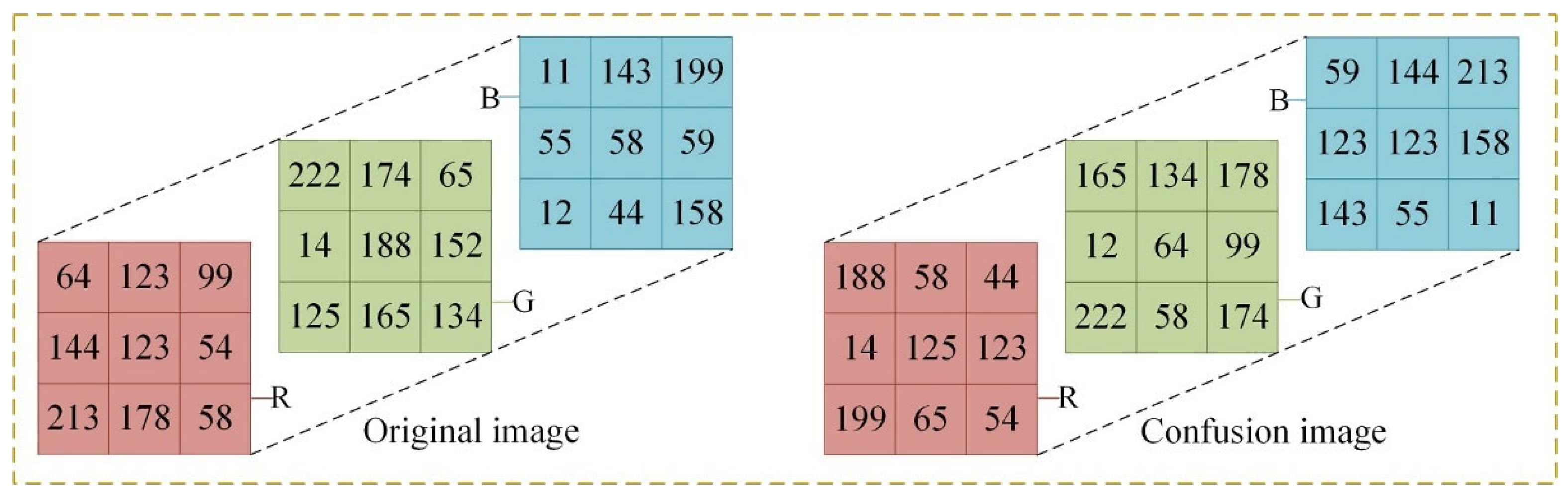
  • Particle swarm foraging algorithms are designed to disrupt color image planar pixel positions cross-channel;
  • Tests and performance analysis are conducted, and the scheme has good security and statistical performance.

2. Basic Theory

2.1. Five-Dimensional Discrete Map

As chaotic systems possess the need for cryptographic foundations and hyperchaotic systems possess more complex dynamical behaviors, this article uses our lab’s chaotic model of discrete memristive coupled neurons [39]. The model is a memristor coupled by Chialvo and Rulkov neurons (C-M-R) and has multiple types of hyperchaotic behavior. The C-M-R mathematical model is shown in Equation (1):
{ x 1 ( i + 1 ) = ( x 1 ( i ) ) 2 e ( y 1 ( i ) x 1 ( i ) ) + δ k r ( α cos ( π z ( i ) 2 ) + β ) ( x 1 ( i ) x 2 ( i ) ) y 1 ( i + 1 ) = a y 1 ( i ) b x 1 ( i ) + c z ( i + 1 ) = z ( i ) + x 1 ( i ) x 2 ( i ) x 2 ( i + 1 ) = γ 1 + ( x 2 ( i ) ) 2 + y 2 ( i ) + k r ( α cos ( π z ( i ) 2 ) + β ) ( x 1 ( i ) x 2 ( i ) ) y 2 ( i + 1 ) = y 2 ( i ) u ( x 2 ( i ) σ )
where x1(i) and y1(i) are condition variables of the Chialvo neuron model; x2(i) and y2(i) are the condition variables of the Rulkov neuron model. z(i) is the memristor model, which serves as a bridge between the two neurons.

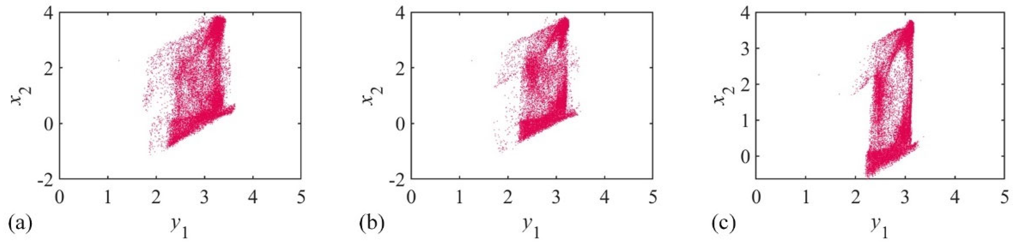
2.1.1. Phase Diagram

The trajectory of a discrete map is iterated through its state variables. The iterative states of the state variables are depicted with the use of phase diagrams.
We set the phase diagram parameters for C-M-R as (ε, kr, α, β, a, b, γ, μ, σ) = (0.1, 0.3, −0.35, −0.65, 0.7, 0.18, 4.8, 0.01, 1.35), with an initial value of (x1(1), x2(1), z(1), x2(1), y2(1)) = (−1, −1, 0, 1, 1), the result is shown in Figure 1.

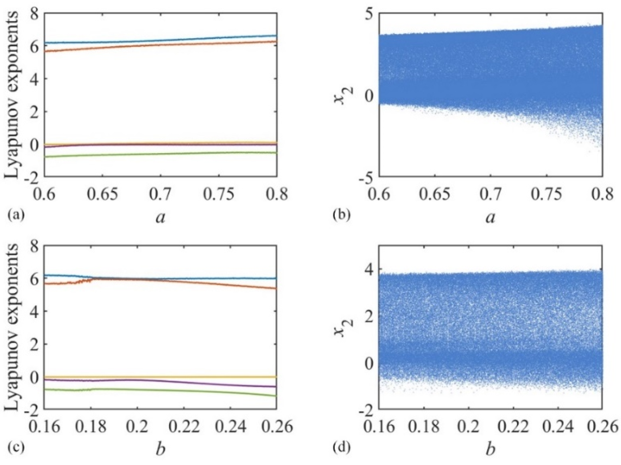
2.1.2. LEs and Bifurcation Diagram

For a discrete system, if one LE’s straight line is greater than 0, it is considered a chaotic state. If two LEs’ lines are greater than 0, the system is considered to be in a hyperchaotic state. The bifurcation diagram clearly shows whether the system is in a periodic or chaotic state. LEs and bifurcation diagrams are complementary to each other. The test is performed on parameter a and parameter b. The result is shown in Figure 2, which clearly shows that the two LEs’ lines are greater than 0 and the bifurcation diagram is in a chaotic state. It can be concluded from the above that the model is hyperchaotic with this parameter and its dynamics are more complex and suitable for cryptographic applications.

2.1.3. Spectral Entropy

In chaotic systems, spectral entropy (SE) is a kind of metric that characterizes the dynamics of the system from the aspect of frequency domain. SE is obtained through Fourier transforming the time series of the system to obtain the spectral distribution, and then normalizing the spectral distribution and calculating the entropy value. This value shows whether the energy distribution of the system at different frequencies is uniform or chaotic.
SE is often used to measure the degree of nonlinearity and complexity of the system. If the SE is high, the spectral distribution of the system is more uniform, the energy distribution at different frequencies is more chaotic, and the system may be in a chaotic state. Conversely, if the SE is low, it indicates that the spectral distribution of the system is more concentrated, the energy is more concentrated at certain frequencies, and the system may be in a periodic or regular state. The SE of the C-M-R model is higher, which is shown in Figure 3. At this time, the system is in a chaotic state.

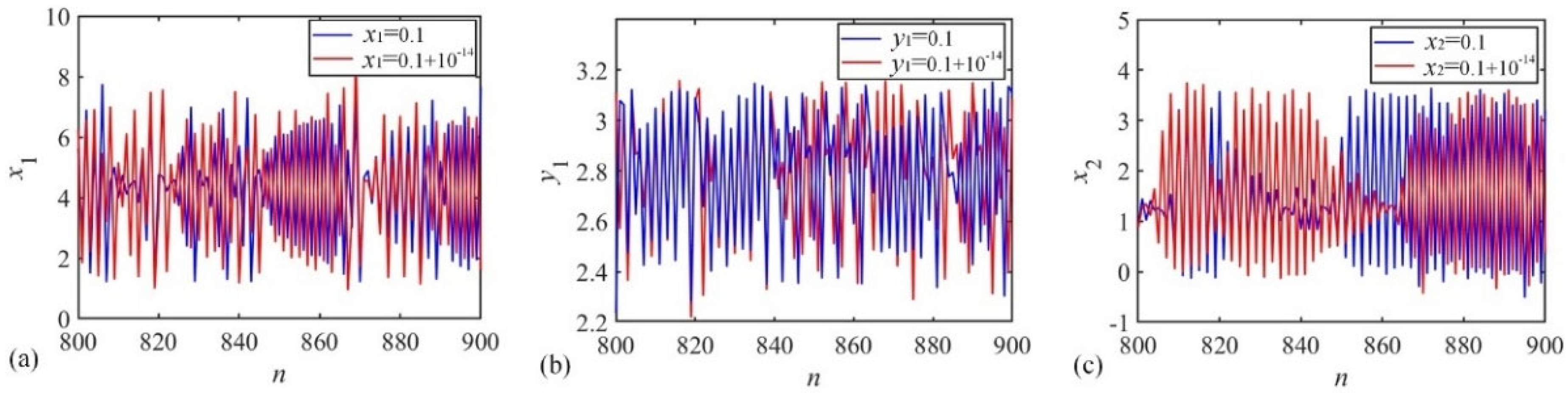
2.1.4. Initial Value Sensitivity

Initial value sensitivity practically satisfies the needs of cryptography. In chaotic systems, initial value sensitivity means that the system is very sensitive to small changes in the initial conditions, i.e., a small difference in the initial value can lead to a large difference in the evolutionary trajectory of the system.
Initial value sensitivity ensures that a small change in the key or initial value will result in a completely different chaotic sequence, thus realizing the high-strength encryption of the image. Only a decryptor with the same key can correctly restore the plaintext image, while for an attacker with an unknown key, it becomes very difficult to break the encryption process. The chaotic sequences of the initial value and the initial value after scrambling interference are reflected in Figure 4, and it is seen that the chaotic sequences are different.

2.1.5. NIST Test

To better verify the suitability of chaotic systems for image encryption, chaotic sequences are verified for randomness testing. The NIST test is a commonly used test for sequence randomness and contains 15 tests. The chaotic system generates chaotic sequences of a length of 20 million and obtains 160 million binary data as data samples for the randomness test. The test results are shown in Table 1, the p-value and pass rate. A sequence passes the randomness test when the p-value of 15 tests is greater than or equal to 0.01 and the pass rate is greater than 96%. The results show that the chaotic series passes all the tests, thus proving that the chaotic system has randomness and is suitable for image encryption algorithms.

2.2. DWT Compression

DWT is a commonly used image compression technique due to its excellent time domain analysis capability. Firstly, using the DWT technique, the image is decomposed into four sub-bands. the low-frequency sub-band is LL, and the high-frequency sub-bands are LH, HL and HH. It is worth noting that the low-frequency LL retains an approximation of the original image. Then, encryption and decryption are performed with LL. The final image is reconstructed using the LL sub-band. This DWT compression and reduction process is shown in Figure 5.

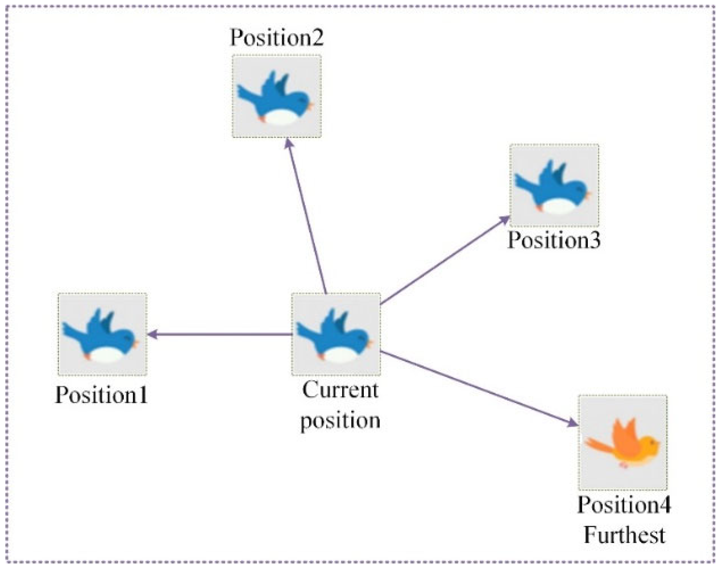
2.3. Particle Swarm Foraging Algorithm (PSFA)
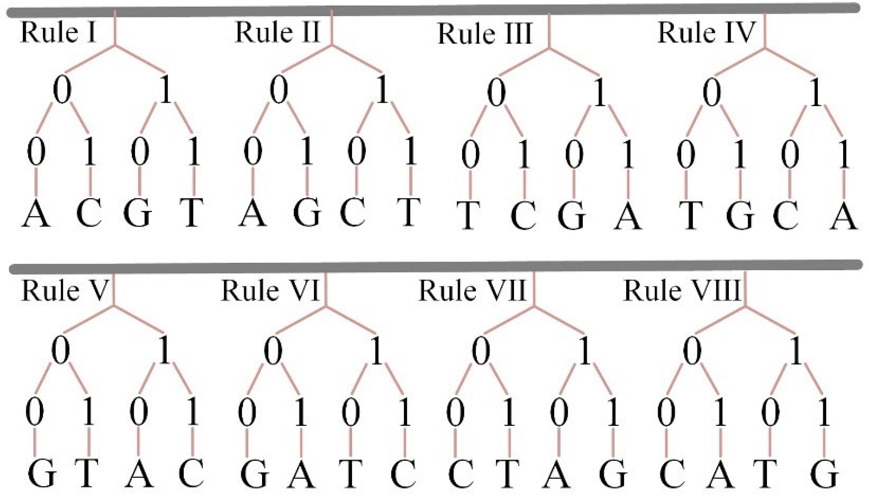
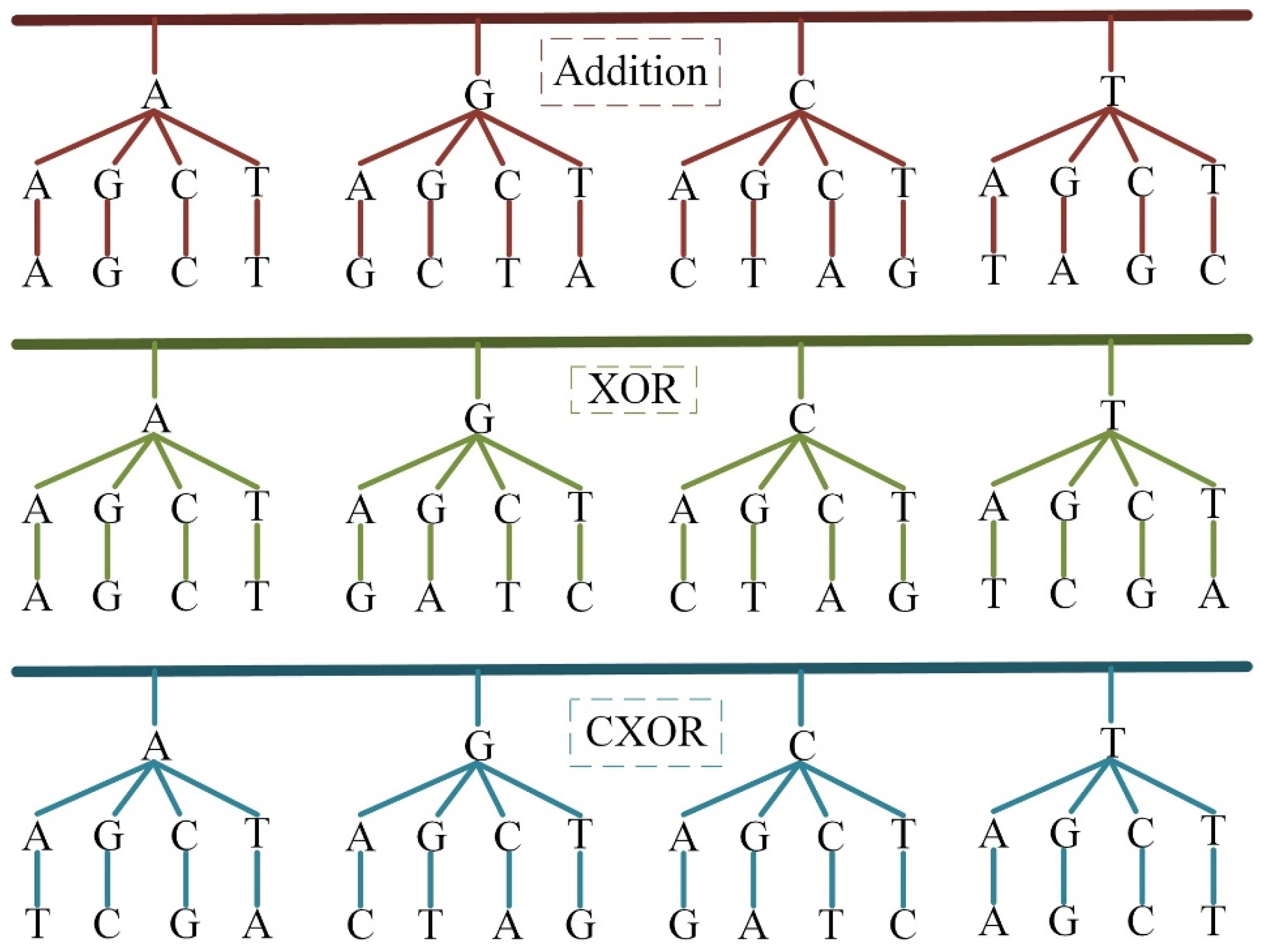
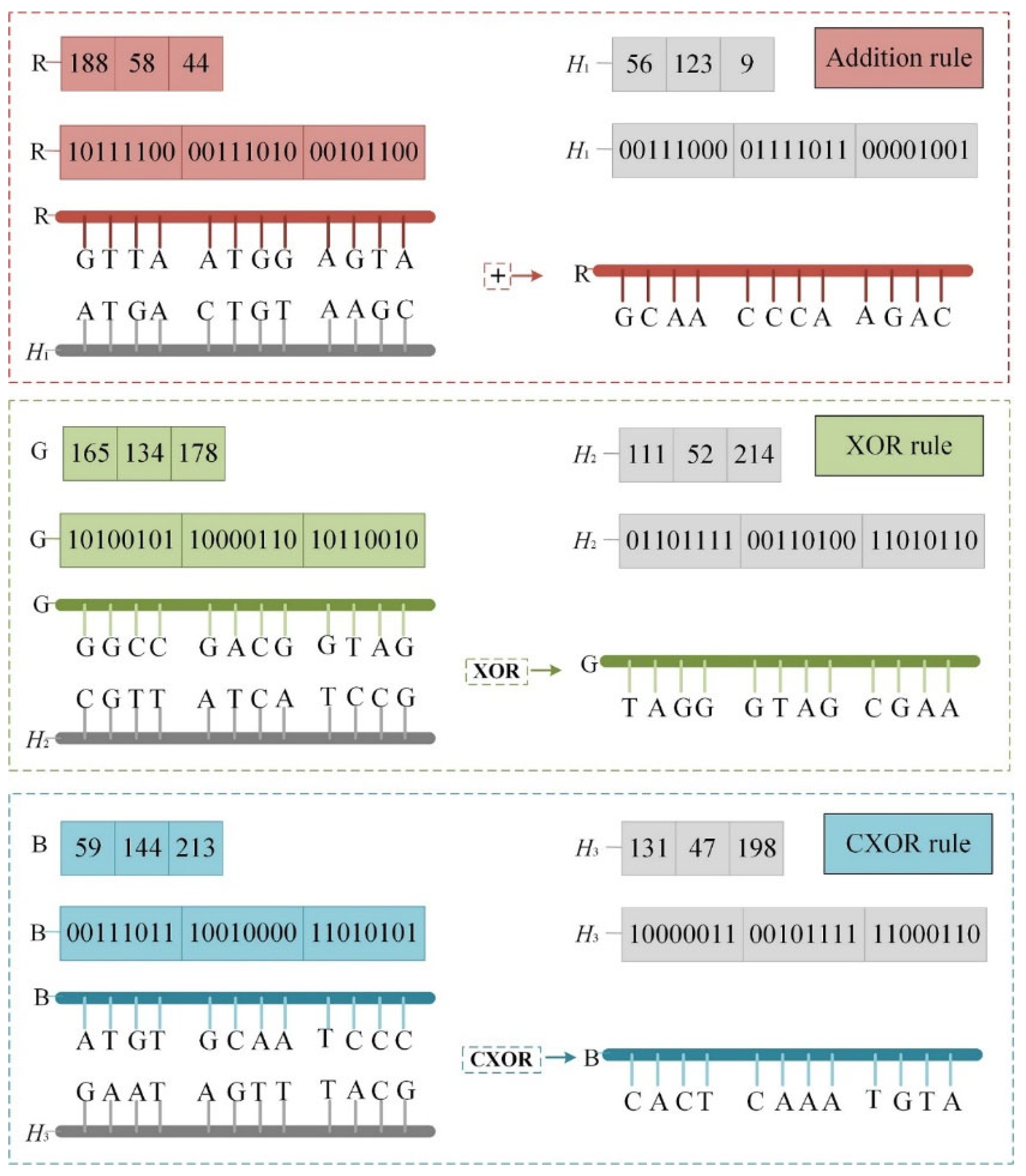
The traditional particle swarm optimization algorithm finds the minimum foraging path through individuals or populations cooperating with each other. This property is utilized to disrupt the image pixels. As shown in Figure 6, four positions are randomly generated each time using the chaotic system, and after calculation, the largest direction is selected as the current moving direction. Specifically, the pixel values are traversed after selecting the farthest direction to move in.

2.4. DNA Encoding

The earliest signs of DNA are found in living organisms and consist of two complementary strands of nucleotide bases. The four nucleotide bases are A, G, C and T. They are complementary to each other, and 0 and 1 are also complementary. Therefore, the pixel values are converted into eight-bit binary values and split into combinations of 00, 01, 10, and 11 to associate with A, G, C, and T. This process of nucleotide bases from binary values is shown in Figure 7.
In the DNA coding stage, three different rules are used for the arithmetic, namely DNA addition, DNA XOR and DNA-complementary XOR (CXOR). The results are displayed in Figure 8. The color image consists of three channels, the red channel using DNA addition, the green channel adopting XOR and the blue channel utilizing CXOR.

3. Encryption Scheme and Decryption Scheme

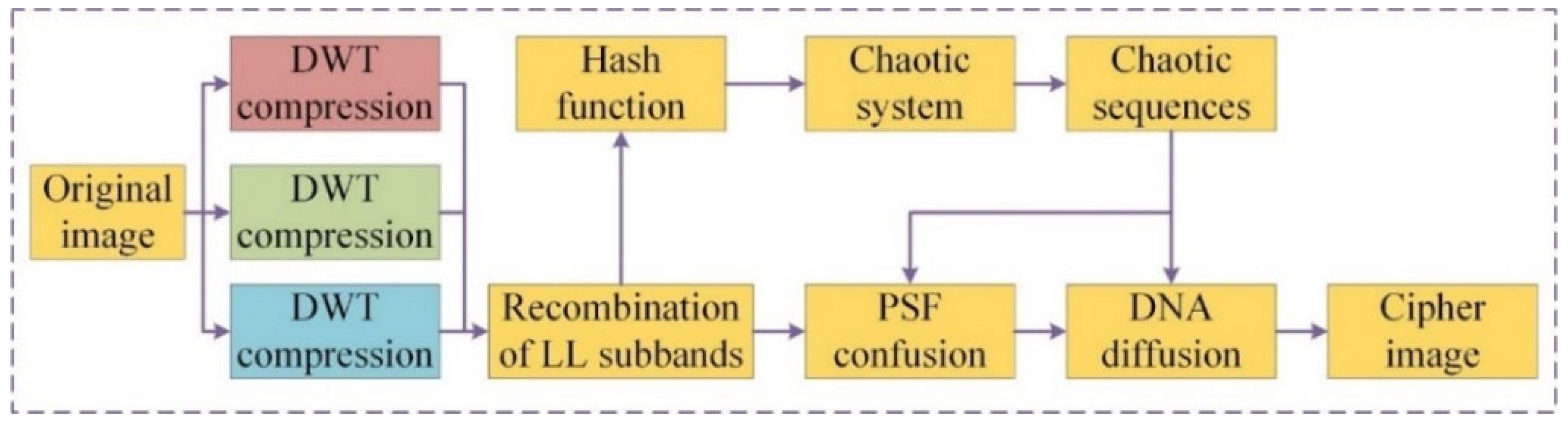
3.1. The Complete Encryption Process

This encryption process is shown in Figure 9. First, the color image’s three channels are converted via DWT, and LL sub-bands are retained. The LL sub-bands are used in conjunction with the Hash function for assigning initial values to the chaotic system. Then, the LL sub-band is confused and diffused to generate the cipher image.

3.2. Encryption Process

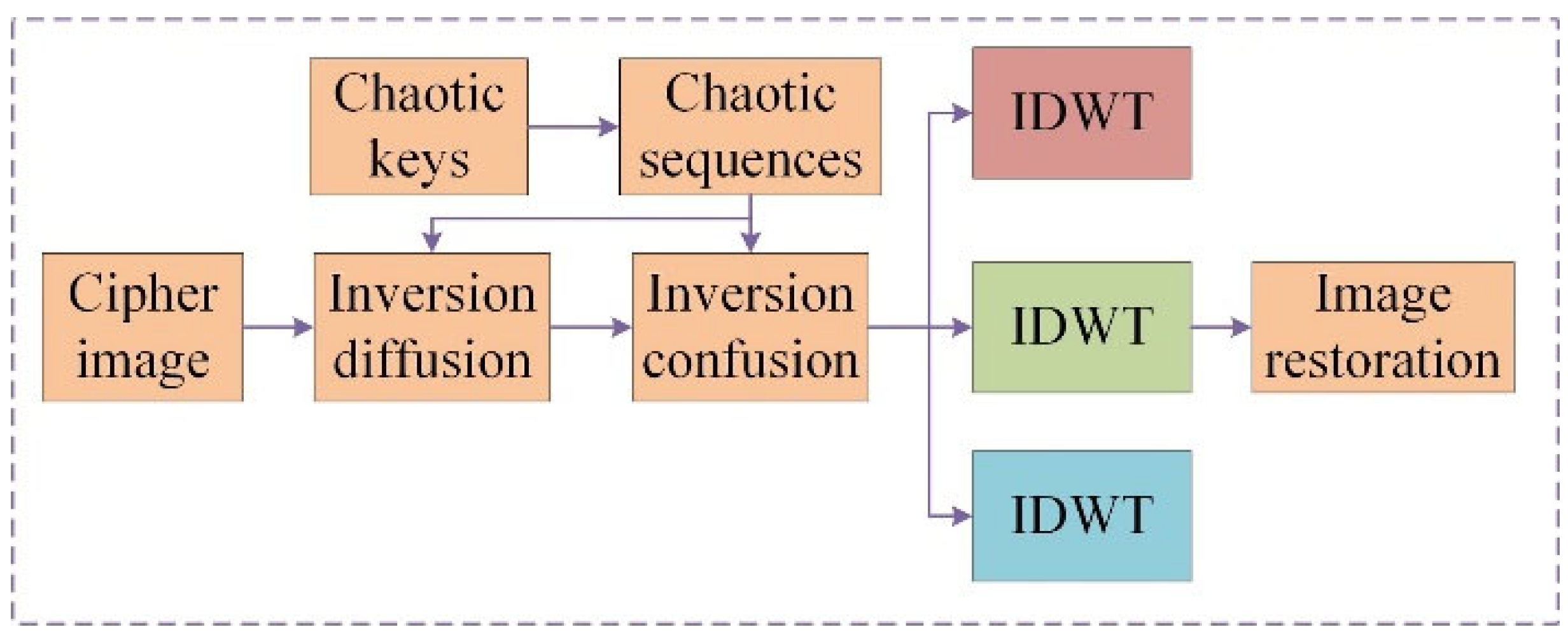
3.2.1. DWT Compression

Step 1: Input a color image, T, and record its size as M × N × 3. Split the color image into TR, TG and TB channels.
Step 2: Each channel undergoes DWT decomposition into four sub-bands: LL, HL, LH and HH.
{ [ L L R , L H R , H L R , H H R ] = D W T ( T R ) [ L L G , L H G , H L G , H H G ] = D W T ( T G ) . [ L L B , L H B , H L B , H H B ] = D W T ( T B )
Step 3: The low-frequency sub-band information, LL, is retained and re-fused into a new matrix, T1.
{ T 1 ( : , : , 1 ) = L L R T 1 ( : , : , 2 ) = L L G , T 1 ( : , : , 3 ) = L L B
where the T1 size is (M/4) × (N/4) × 3.

3.2.2. Confusion Process

Step 1: The low-frequency sub-band module can be obtained via the DWT technique, and the data type of this module is not suitable for encryption. Therefore, the data need to be further processed.
Step 2: The range of values for T1 is [min(min(T1)), max(max(T1))], with Equation (4) creating the range of the new T2 value in [0, 255]:
T 2 = floor ( T 1 min ( min T 1 ) max ( max T 1 ) min ( min T 1 ) ) × 255 .
Step 3: A rounding operation is performed on T2 and the fractional part is discarded to obtain T3.
T 3 = floor ( T 2 ) .
Step 4: T3 is input into the Hash-256 function to obtain a set of 256-bit Hash sequences. The Hash sequences are computed to be used as initial values for the hyperchaotic system.
{ f 1 = mod ( 10 2 × mean ( ( K ( 1 : 8 ) K ( 9 : 16 ) ) ) , L ) f 2 = mod ( 10 2 × mean ( ( K ( 17 : 24 ) K ( 25 : 32 ) ) ) , L ) f 3 = mod ( 10 2 × mean ( ( K ( 25 : 32 ) K ( 33 : 40 ) ) ) , L ) , f 4 = mod ( 10 2 × mean ( ( K ( 33 : 40 ) K ( 41 : 48 ) ) ) , L ) f 5 = mod ( 10 2 × mean ( ( K ( 49 : 56 ) K ( 57 : 64 ) ) ) , L )
where K represents the Hash sequences and L is the Hash length.
Step 5: The chaotic system generates x1, y1, z, x2 and y2, which are computed to obtain the desired chaotic sequence.
{ X 1 = floor ( mod ( x 1 × 10 12 , M ) ) + 1 Y 1 = floor ( mod ( y 1 × 10 12 , N ) ) + 1 Z = floor ( mod ( z × 10 12 , 3 ) ) + 1 , X 2 = floor ( mod ( x 2 × 10 12 , M ) ) + 1 Y 2 = floor ( mod ( y 2 × 10 12 , N ) ) + 1
where x1 and x2 are random lengths, and y1 and y2 are random widths. z is the parameter required to span the channel.
Step 6 (the PSFA stage): For the traversal of the pixel values, each point of the pixel value has a total of four random points to be exchanged. Thus, the furthest-distance pixel point is selected.
{ fitness ( 1 ) = ( k x X 1 ( k x , k y , k z ) ) 2 + ( k y Y 1 ( k x , k y , k z ) ) 2 fitness ( 2 ) = ( k x X 1 ( k x , k y , k z ) ) 2 + ( k y Y 2 ( k x , k y , k z ) ) 2 fitness ( 3 ) = ( k x X 2 ( k x , k y , k z ) ) 2 + ( k y Y 1 ( k x , k y , k z ) ) 2 , fitness ( 4 ) = ( k x X 2 ( k x , k y , k z ) ) 2 + ( k y Y 2 ( k x , k y , k z ) ) 2 [ index ] = max ( fitness )
Step 7: It is worth noting that the results of each traversal may swap pixel values in different channels. This choice is selected by the chaotic sequence. Equation (9) represents four ways to make this choice. Applying the rules of Equations (7) and (9), the results are shown in Figure 10.
{ t = T 1 ( k x , k y , k z ) T 1 ( k x , k y , k z ) = T 1 ( X ( k x , k y , k z ) , Y ( k x , k y , k z ) , Z ( k x , k y , k z ) ) . T 1 ( k x , k y , k z ) = t

3.2.3. Diffusion Process

Step 1: The confused image, T3, is converted to 8-bit binary values via data type conversion.
{ T R = dec 2 bin ( T 3 ( : , : , 1 ) T G = dec 2 bin ( T 3 ( : , : , 2 ) . T B = dec 2 bin ( T 3 ( : , : , 3 )
Step 2: Data type conversion is performed on chaotic sequences as well.
{ H 1 = dec 2 bin ( X 1 ( : , : , 1 ) H 2 = dec 2 bin ( X 1 ( : , : , 2 ) . H 3 = dec 2 bin ( X 1 ( : , : , 3 )
Step 3: Three rules of DNA operation are used in Figure 2 that are used for the R channel; the XOR rule is used for the G channel and the CXOR rule is used for the B channel. The first rule in Figure 1 is chosen as the DNA encoding rule, and the encryption process is indicated in Figure 11.
{ T R = T R + H 1 T G = T G H 2 . T B = T B H 3 ¯

3.3. Decryption Process

The decryption process performs inverse diffusion and inverse confusion operations. Firstly, the chaotic key is input into the chaotic system to obtain the chaotic sequence needed for decryption. Second, inverse diffusion is performed, including the DNA decoding process. Then, inverse disarray is performed. Finally, the image is recovered with the use of the IDWT technique. A detailed decryption flowchart is presented in Figure 12.

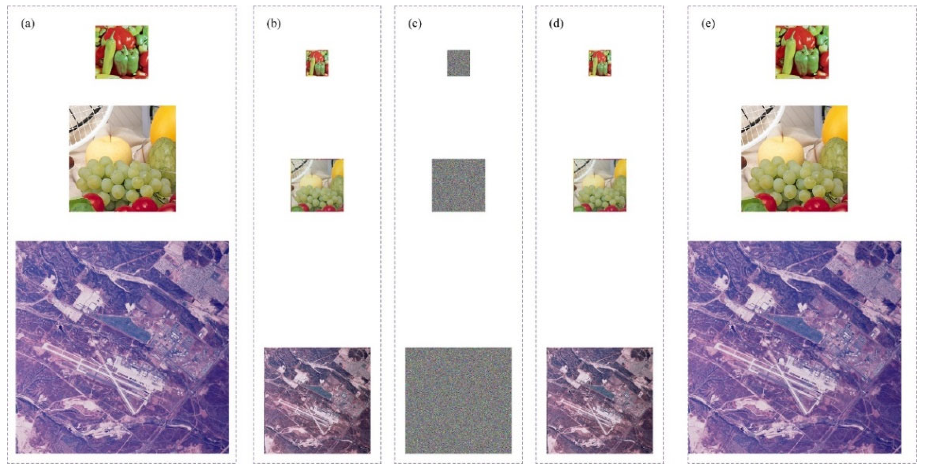
3.4. Simulation Results

This article makes use of ‘Peppers’ (256 × 256 × 3), ‘Fruits’ (512 × 512 × 3) and ‘2.2.05′ (1024 × 1024 × 3) color images. The simulation results are indicated in Figure 13. The simulation result shows that the restored image is identical to the plaintext image except for the image brightness.

4. Security Analysis

4.1. Quality Reconstruction Analysis

The DWT technique is used to decompose the color image into bands of different scales. The LL band retains the general outline and main structure of the original image. On the decryption side, IDWT reduction of the image is performed. However, lossy compression brings about a loss of quality in the image. PSNR is a common measure of image quality and is usually measured in decibels (dB). The higher the PSNR, the better the image is recovered. The PSNR test is shown in Table 2. The PSNR is calculated as in Equation (13).
PSNR = 10 lg M × N × 255 2 i = 1 M j = 1 N | T ( i , j ) Y ( i , j ) | 2 .
There are around 30 PSNR test results, which are compared with the results of other compression methods using ‘Peppers’ images with a size of 256 × 256, as shown in Table 3.

4.2. Histogram Analysis

Histograms are the basis of statistical analysis and reflect the number of pixel values per pixel in an image. Some pixels in the original image are particularly focused, while others have a very small number of pixel values, exposing the pixel value characteristics of the original image. Normally, the histogram of an encrypted image should show a uniform distribution with no obvious peaks or features to ensure that the encrypted image does not leak information from the plaintext image.
The histogram pixel values of the plaintext image with uneven features, and the histogram pixels of the cipher image with uniform pixels, shown in Figure 14, indicate that the attacker cannot analyze the cipher image to obtain information about the features of the pixels of the normal image.

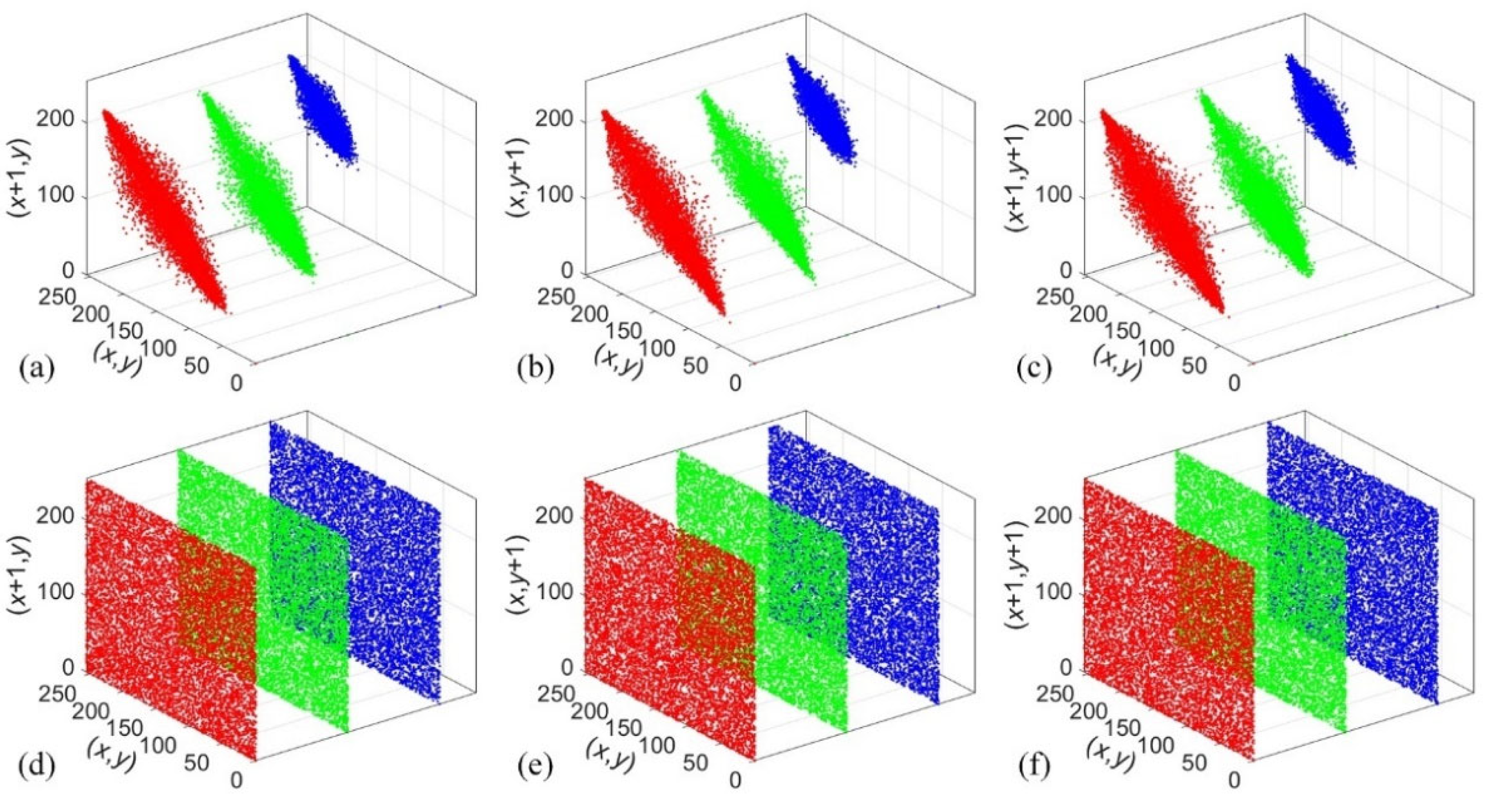
4.3. Correlation Analysis

In plaintext images, the correlation between adjacent pixel values is high, and an attacker can obtain the image by analyzing the correlation. In contrast, the original image id encrypted so that the correlation between its pixels is destroyed, and there is essentially no correlation between the pixel values in the encrypted image.
The neighboring pixels in three different directions of the original grayscale image, ‘2.2.05′, are decomposed and the neighboring pixels, as shown in Figure 15. The correlation coefficient of the neighboring pixels of the image is calculated using the following equation.
r x , y = E [ ( x E ( x ) ) ( y E ( y ) ) ] σ x σ y
where E(x) is the expected value of x and σx is the standard deviation of x.
Table 4 lists the different correlation coefficients for the three channels of the color image ‘Peppers’. From the table, it can be concluded that the encrypted neighbor correlation coefficients are close to 0 and can effectively resist statistical attacks.

4.4. Information Entropy

Information entropy (IE) is a measure of image complexity and information content. IE describes the probability of each pixel appearing. The theoretical value of IE is usually considered to be 8 [57], and the IE of this test is very close to the theoretical value. The IE value of the encrypted image should be high enough to indicate that the information in the image is uniformly and randomly spread so that an attacker cannot derive useful information from it. The results of this information entropy is shown in Table 5.

4.5. Key Space

The size of the key space determines the resistance of the encryption scheme to exhaustive attacks. When the key space is larger than 2100 [58], it can resist exhaustive attacks, and the larger the key space, the smaller the probability that the encryption scheme will be cracked. By slightly perturbing each parameter in the decryption process, the key space of each parameter can be obtained, and the total key space can be obtained after calculation. Table 6 shows the key space, and Table 7 shows the references for it, which show that our key space is much larger and resistant to brute-force cracking.

4.6. Key Sensitivity

To test the key sensitivity performance, a color image of ‘2.2.05′ is used. Encryption is performed using deterministic parameters, and its encryption result is T1. Then, scrambling is performed on each parameter separately, and its encryption result is T2. The difference between the T1 image and T2 image is evaluated by the rate of change in pixel values (NPCR) of the two images (normally encrypted and scrambled, encrypted images). The scheme has high key sensitivity, and the NPCR results are shown in Table 8.
NPCR ( T 1 , T 2 ) = 1 M N i = 1 M j = 1 N | Sign ( T 1 ( i , j ) T 2 ( i , j ) ) | × 100 % .
where Sign(•) is a symbolic function.
In the test, the specifications of the color images ‘Peppers’ and ‘2.2.05′ are encrypted with the normal key and revised with one key, respectively; the results are shown in Figure 16.

4.7. Differential Attack

Differential attacks are a common method for attackers to use to break algorithms. The attacker randomly changes one pixel point of the original image to obtain the encrypted image and analyzes the difference between the two cipher images to break the scheme.
In the differential attack test, the original image is encrypted twice; the first time it is encrypted involves normal encryption, T1, and the second time, the attacker randomly changes one pixel point of the original image to obtain T2. Since the scheme’s plaintext information is associated with the hash function, randomly changing one pixel of the original image will, in turn, result in a different hash sequence. This leads to a change in the initial value of the C-M-R system, and its chaotic sequence, in turn, changes. As a result, the encrypted structure and content change, and in turn, the encrypted image changes.
The difference between T1 and T2 is evaluated using the NPCR and the intensity of change (UACI) of the two images. The results of the tests are indicated in Table 9. As can be seen from Table 10, the percentage change of pixels of this scheme is better than that of other reference schemes.
UACI ( T 1 , T 2 ) = 1 M N i = 0 M j = 0 N | T 1 ( i , j ) T 2 ( i , j ) | 255 0 × 100 % .

4.8. Plain Attack

It is well known that there are four classic types of attacks: cipher attacks, known plaintext attacks, chosen plaintext attacks and chosen cipher attacks. Among them, chosen plaintext attacks are the most powerful attacks. If a cryptosystem is able to withstand these, it can resist other types of attacks.
Due to the specificity of the DWT technique, here, half of the all-black and half of the all-white images are selected, and this result is shown in Figure 17; Figure 17c after this encryption scheme is generated as a noise-like image, which shows that this encryption scheme is able to resist plaintext attacks.

4.9. Robustness

4.9.1. Noise Attack Analysis

As encrypted images are transmitted over the network, they are mostly interfered with by various noises in the channel, such as salt-and-pepper noise (SPN) and Gaussian noise (GN), which makes the recovery of ordinary images more difficult. In this section, the effectiveness of the algorithm against noise attacks is described. Specifically, the color image ‘Fruits’ is used as the decrypted images in the case of ordinary images with test noise. Therefore, the algorithm is robust against noise to a certain extent in this article. The results of this noise test is shown in Figure 18.

4.9.2. Shearing Attack Analysis

A shear attack is an attack that cuts against the pixels of an image. An attacker may cut and crop specific portions to gain access to sensitive information or to break encryption algorithms. The encrypted image for this test is the color image ‘Fruits’, and the cipher image is sheared with 6.25%, 12.5%, and 25% shearing attack to regain the cipher image. The recovered image can be seen in the figure. Thus, this algorithm has some resistance against shearing attacks. The result of this shearing attack is shown in Figure 19.

4.10. Comparing Our Scheme with Other Encryption Schemes

In summary, various performance metrics discussed above are considered to compare the proposed encryption scheme with other state-of-the-art chaotic and nonchaotic encryption schemes in Table 11. Refs. [65,66,67] present chaotic encryption schemes. Ref. [68] uses adaptive Fourier decomposition (AFD) for image encryption. When comparing the proposed DWT-compressed encryption scheme based on chaos theory with the above schemes, it can be concluded that our scheme is superior.

5. Conclusions

An encryption scheme with discrete memristive coupled neurons and DWT compression is introduced in this article. The behavior dynamics of chaotic systems are analyzed by means of phase diagrams, LEs, bifurcation diagrams and SE. The color image is compressed via DWT, and the parameters related to the color image information are obtained using the Hash function, i.e., a set of plaintexts corresponds to a set of keys. The pseudo-random sequence obtained using the chaotic system is used for encryption. The pixel positions of the color image are exchanged using chaotic sequences as a tool guided by the movement rules of the PSFA. DNA encoding rules are utilized to further secure the image. Simulation results show that the DWT technique and encryption scheme can compress color images of different sizes into a quarter of the original image capacity and encrypt them into unrecognizable images. The security analysis shows that the C-M-R discrete map introduces a large key space to defend the scheme against exhaustive attacks. Histogram, correlation and information entropy statistics show that the PSFA and DNA encoding can withstand various statistical analyses. Differential attack analysis shows the superiority of our algorithms in terms of security performance. The encrypted image retains its ability for quality recovery even when the encrypted image is subjected to external disturbances such as malicious clipping and noise contamination.
In future work, as DWT compression can only compress the image into a quarter of the original image, future improvements in the DWT compression technique are required to fulfill the arbitrary compression ratio of the image. Moreover, the next step is to design a new encryption scheme to satisfy image encryption, as the DNA encoding process is time-consuming.

Author Contributions

C.C. designed and carried out the experiments, analyzed the data and wrote the manuscript. Y.C. provided theoretical guidance for this paper. X.X. and X.B. carried out the experiments and improved the algorithm. All authors have read and agreed to the published version of the manuscript.

Funding

This work was funded by the National Natural Science Foundation of China (Grant No. 62061014), technological innovation projects in the field of artificial intelligence in Liaoning province (Grant Nos. 2023JH26/10300011), and basic scientific research projects in department of education of Liaoning Province (Grant No. JYTZD2023021).

Data Availability Statement

No new data were created or analyzed in this study.

Conflicts of Interest

The authors declare no conflicts of interest.

References

  1. Chen, X.; Mou, J.; Cao, Y.; Banerjee, S. Chaotic Multiple-Image Encryption Algorithm Based on Block Scrambling and Dynamic DNA Coding. Int. J. Bifurc. Chaos 2023, 33, 2350190. [Google Scholar] [CrossRef]
  2. Zhang, Z.; Cao, Y.; Jahanshahi, H.; Mou, J. Chaotic color multi-image compression-encryption/LSB data type steganography scheme for NFT transaction security. J. King Saud Univ.-Comput. Inf. Sci. 2023, 35, 101839. [Google Scholar] [CrossRef]
  3. Zhang, Z.; Mou, J.; Banerjee, S.; Cao, Y. A chaotic hierarchical encryption/watermark embedding scheme for multi-medical images based on row–column confusion and closed-loop bi-directional diffusion. Chin. Phys. B 2024, 33, 020503. [Google Scholar] [CrossRef]
  4. Zhang, Z.; Mou, J.; Zhou, N.; Banerjee, S.; Cao, Y. Multi-cube encryption scheme for multi-type images based on modified Klotski game and hyperchaotic map. Nonlinear Dyn. 2024, 112, 5727–5747. [Google Scholar] [CrossRef]
  5. Zhang, Z.; Zhou, N.; Sun, B.; Banerjee, S.; Mou, J. Multimedia healthcare cloud personal archives security system based on compressed sensing and multi-image encryption. J. Frankl. Inst. 2024, 361, 106844. [Google Scholar] [CrossRef]
  6. Alawida, M. A novel DNA tree-based chaotic image encryption algorithm. J. Inf. Secur. Appl. 2024, 83, 103791. [Google Scholar] [CrossRef]
  7. Almasoud, A.S.; Alabduallah, B.; Alqahtani, H.; Aljameel, S.S.; Alotaibi, S.S.; Mohamed, A. Chaotic image encryption algorithm with improved bonobo optimizer and DNA coding for enhanced security. Heliyon 2024, 10, E25257. [Google Scholar] [CrossRef]
  8. Cao, P.; Teng, L. A chaotic image encryption algorithm based on sliding window and pseudo-random stack shuffling. Nonlinear Dyn. 2024, 112, 13539–13569. [Google Scholar] [CrossRef]
  9. Li, L. A novel chaotic map application in image encryption algorithm. Expert Syst. Appl. 2024, 252, 124316. [Google Scholar] [CrossRef]
  10. Rehman, M.U. Quantum-enhanced chaotic image encryption: Strengthening digital data security with 1-D sine-based chaotic maps and quantum coding. J. King Saud Univ.-Comput. Inf. Sci. 2024, 36, 101980. [Google Scholar] [CrossRef]
  11. Cai, C.; Cao, Y.; Jahanshahi, H.; Mou, J.; Sun, B. 2D and 3D compatible chaotic image encryption system based on checkers rules and shift register. J. Frankl. Inst. 2024, 361, 106874. [Google Scholar] [CrossRef]
  12. Cai, C.; Wang, Y.; Cao, Y.; Sun, B.; Mou, J. Multiple remote sensing image encryption scheme based on saliency extraction and magic cube circular motion. Appl. Intell. 2024, 54, 5944–5960. [Google Scholar] [CrossRef]
  13. Gao, X.; Mou, J.; Banerjee, S.; Cao, Y.; Xiong, L.; Chen, X. An effective multiple-image encryption algorithm based on 3D cube and hyperchaotic map. J. King Saud Univ.-Comput. Inf. Sci. 2022, 34, 1535–1551. [Google Scholar] [CrossRef]
  14. Gao, X.; Mou, J.; Banerjee, S.; Zhang, Y. Color-gray multi-image hybrid compression–encryption scheme based on BP neural network and knight tour. IEEE Trans. Cybern. 2023, 53, 5037–5047. [Google Scholar] [CrossRef] [PubMed]
  15. Sang, Y.; Sang, J.; Alam, M.S. Image encryption based on logistic chaotic systems and deep autoencoder. Pattern Recognit. Lett. 2022, 153, 59–66. [Google Scholar] [CrossRef]
  16. Xian, Y.; Wang, X.; Wang, X.; Li, Q.; Yan, X. Spiral-transform-based fractal sorting matrix for chaotic image encryption. IEEE Trans. Circuits Syst. I Regul. Pap. 2022, 69, 3320–3327. [Google Scholar] [CrossRef]
  17. Jamal, S.S.; Hazzazi, M.M.; Khan, M.F.; Bassfar, Z.; Aljaedi, A.; ul Islam, Z. Region of interest-based medical image encryption technique based on chaotic S-boxes. Expert Syst. Appl. 2024, 238, 122030. [Google Scholar] [CrossRef]
  18. Niu, Y.; Zhou, H.; Zhang, X. Image encryption scheme based on improved four-dimensional chaotic system and evolutionary operators. Sci. Rep. 2024, 14, 7033. [Google Scholar] [CrossRef]
  19. Toktas, A.; Erkan, U.; Gao, S.; Pak, C. A robust bit-level image encryption based on Bessel map. Appl. Math. Comput. 2024, 462, 128340. [Google Scholar] [CrossRef]
  20. Toktas, F.; Erkan, U.; Yetgin, Z. Cross-channel color image encryption through 2D hyperchaotic hybrid map of optimization test functions. Expert Syst. Appl. 2024, 249, 123583. [Google Scholar] [CrossRef]
  21. Zhang, H.; Hu, H. An image encryption algorithm based on a compound-coupled chaotic system. Digit. Signal Process. 2024, 146, 104367. [Google Scholar] [CrossRef]
  22. Zhou, R.; Yu, S. Break an enhanced plaintext-related chaotic image encryption algorithm. Chaos Solitons Fractals 2024, 181, 114623. [Google Scholar] [CrossRef]
  23. Alawida, M. A Novel Image Encryption Algorithm Based on Cyclic Chaotic Map in Industrial IoT Environments. IEEE Trans. Ind. Inform. 2024. [Google Scholar] [CrossRef]
  24. Darani, A.Y.; Yengejeh, Y.K.; Pakmanesh, H.; Navarro, G. Image encryption algorithm based on a new 3D chaotic system using cellular automata. Chaos Solitons Fractals 2024, 179, 114396. [Google Scholar] [CrossRef]
  25. Es-sabry, M.; El Akkad, N.; Khrissi, L.; Satori, K.; El-Shafai, W.; Altameem, T.; Rathore, R.S. An efficient 32-bit color image encryption technique using multiple chaotic maps and advanced ciphers. Egypt. Inform. J. 2024, 25, 100449. [Google Scholar] [CrossRef]
  26. Kocak, O.; Erkan, U.; Toktas, A.; Gao, S. PSO-based image encryption scheme using modular integrated logistic exponential map. Expert Syst. Appl. 2024, 237, 121452. [Google Scholar] [CrossRef]
  27. Kumar, A.; Dua, M. Image encryption using a novel hybrid chaotic map and dynamic permutation−diffusion. Multimed. Tools Appl. 2024, 83, 32789–32812. [Google Scholar] [CrossRef]
  28. Kumar, S.; Sharma, D. A chaotic based image encryption scheme using elliptic curve cryptography and genetic algorithm. Artif. Intell. Rev. 2024, 57, 87. [Google Scholar] [CrossRef]
  29. Deng, Q.; Wang, C.; Lin, H. Chaotic dynamical system of Hopfield neural network influenced by neuron activation threshold and its image encryption. Nonlinear Dyn. 2024, 112, 6629–6646. [Google Scholar] [CrossRef]
  30. Deng, Q.; Wang, C.; Lin, H. Memristive Hopfield neural network dynamics with heterogeneous activation functions and its application. Chaos Solitons Fractals 2024, 178, 114387. [Google Scholar] [CrossRef]
  31. Han, Z.; Al-Barakati, A.A.; Jahanshahi, H.; Mou, J. A novel circuit based on memristor-memcapacitor with extreme multistability. Nonlinear Dyn. 2024, 112, 4863–4877. [Google Scholar] [CrossRef]
  32. Han, Z.; Sun, B.; Banerjee, S.; Mou, J. Biological neuron modeling based on bifunctional memristor and its application in secure communication. Chaos Solitons Fractals 2024, 184, 115020. [Google Scholar] [CrossRef]
  33. Li, J.; Wang, C.; Deng, Q. Symmetric multi-double-scroll attractors in Hopfield neural network under pulse controlled memristor. Nonlinear Dyn. 2024, 112, 14463–14477. [Google Scholar] [CrossRef]
  34. Lin, H.; Wang, C.; Sun, Y. A universal variable extension method for designing multiscroll/wing chaotic systems. IEEE Trans. Ind. Electron. 2023, 71, 7806–7818. [Google Scholar] [CrossRef]
  35. Ma, Y.; Mou, J.; Banerjee, S.; Miao, M. A quartic nonlinear flux-controlled memristor model and its application in chaotic system. Appl. Comput. Math. 2023, 22, 317–337. [Google Scholar]
  36. Tang, D.; Wang, C.; Lin, H.; Yu, F. Dynamics analysis and hardware implementation of multi-scroll hyperchaotic hidden attractors based on locally active memristive Hopfield neural network. Nonlinear Dyn. 2024, 112, 1511–1527. [Google Scholar] [CrossRef]
  37. Wang, C.; Liang, J.; Deng, Q. Dynamics of heterogeneous Hopfield neural network with adaptive activation function based on memristor. Neural Netw. 2024, 178, 106408. [Google Scholar] [CrossRef] [PubMed]
  38. Wang, C.; Tang, D.; Lin, H.; Yu, F.; Sun, Y. High-dimensional memristive neural network and its application in commercial data encryption communication. Expert Syst. Appl. 2024, 242, 122513. [Google Scholar] [CrossRef]
  39. Cao, H.; Wang, Y.; Banerjee, S.; Cao, Y.; Mou, J. A discrete Chialvo–Rulkov neuron network coupled with a novel memristor model: Design, Dynamical analysis, DSP implementation and its application. Chaos Solitons Fractals 2024, 179, 114466. [Google Scholar] [CrossRef]
  40. Ma, M.; Lu, Y. Synchronization in scale-free neural networks under electromagnetic radiation. Chaos Interdiscip. J. Nonlinear Sci. 2024, 34, 033116. [Google Scholar] [CrossRef]
  41. Ma, M.; Xiong, K.; Li, Z.; He, S. Dynamical behavior of memristor-coupled heterogeneous discrete neural networks with synaptic crosstalk. Chin. Phys. B 2024, 33, 028706. [Google Scholar] [CrossRef]
  42. Mou, J.; Ma, T.; Banerjee, S.; Zhang, Y. A Novel Memcapacitive-Synapse Neuron: Bionic Modeling, Complex Dynamics Analysis and Circuit Implementation. IEEE Trans. Circuits Syst. I Regul. Pap. 2024, 71, 1771–1780. [Google Scholar] [CrossRef]
  43. Wang, M.; Mou, J.; Qin, L.; Jahanshahi, H. A memristor-coupled heterogeneous discrete neural networks with infinite multi-structure hyperchaotic attractors. Eur. Phys. J. Plus 2023, 138, 1137. [Google Scholar] [CrossRef]
  44. Cao, H.; Chu, R.; Cui, Y. Complex Dynamical Characteristics of the Fractional-Order Cellular Neural Network and Its DSP Implementation. Fractal Fract. 2023, 7, 633. [Google Scholar] [CrossRef]
  45. Ma, T.; Mou, J.; Banerjee, S.; Cao, Y. Analysis of the functional behavior of fractional-order discrete neuron under electromagnetic radiation. Chaos Solitons Fractals 2023, 176, 114113. [Google Scholar] [CrossRef]
  46. Ren, L.; Qin, L.; Jahanshahi, H.; Mou, J. Infinitely Many Coexisting Attractors and Scrolls in a Fractional-Order Discrete Neuron Map. Int. J. Bifurc. Chaos 2023, 33, 2350197. [Google Scholar] [CrossRef]
  47. Wang, M.; Wang, Y.; Chu, R. Dynamical analysis of the incommensurate fractional-order Hopfield neural network system and its digital circuit realization. Fractal Fract. 2023, 7, 474. [Google Scholar] [CrossRef]
  48. Liang, Q.; Zhu, C. A new one-dimensional chaotic map for image encryption scheme based on random DNA coding. Opt. Laser Technol. 2023, 160, 109033. [Google Scholar] [CrossRef]
  49. Naim, M.; Ali Pacha, A. A new chaotic satellite image encryption algorithm based on a 2D filter and Fisher–Yates shuffling. J. Supercomput. 2023, 79, 17585–17618. [Google Scholar] [CrossRef]
  50. Wen, H.; Ma, L.; Liu, L.; Huang, Y.; Chen, Z.; Li, R.; Liu, Z.; Lin, W.; Wu, J.; Li, Y. High-quality restoration image encryption using DCT frequency-domain compression coding and chaos. Sci. Rep. 2022, 12, 16523. [Google Scholar] [CrossRef]
  51. Sha, Y.; Mou, J.; Banerjee, S.; Jahanshahi, H.; Cao, Y. Low-cost multiclass-image encryption based on compressive sensing and chaotic system. Nonlinear Dyn. 2023, 111, 7831–7857. [Google Scholar] [CrossRef]
  52. SaberiKamarposhti, M.; Sahlabadi, M.; Lin, C.-C.; Muniyand, R.C. Using 2d hénon map, cycling chaos and dna sequence for new secure color image encryption algorithm. Arab. J. Sci. Eng. 2024, 49, 4125–4137. [Google Scholar] [CrossRef]
  53. Chen, Y.; Zhang, C.; Cui, M.; Luo, Y.; Wu, T.; Liang, X. Joint compressed sensing and JPEG coding based secure compression scheme in OFDM-PON. Opt. Commun. 2022, 510, 127901. [Google Scholar] [CrossRef]
  54. Huang, S.; Huang, L.; Cai, S.; Xiong, X.; Liu, Y. Novel and secure plaintext-related image encryption algorithm based on compressive sensing and tent-sine system. IET Image Process. 2022, 16, 1544–1557. [Google Scholar] [CrossRef]
  55. Wang, X.; Su, Y. Image encryption based on compressed sensing and DNA encoding. Signal Process. Image Commun. 2021, 95, 116246. [Google Scholar] [CrossRef]
  56. Hadj Brahim, A.; Ali Pacha, A.; Hadj Said, N. A new image compression-encryption scheme based on compressive sensing & classical AES algorithm. Multimed. Tools Appl. 2023, 82, 42087–42117. [Google Scholar]
  57. Wu, Y.; Zhou, Y.; Saveriades, G.; Agaian, S.; Noonan, J.P.; Natarajan, P. Local Shannon entropy measure with statistical tests for image randomness. Inf. Sci. 2013, 222, 323–342. [Google Scholar] [CrossRef]
  58. Seyedzadeh, S.M.; Norouzi, B.; Mosavi, M.R.; Mirzakuchaki, S. A novel color image encryption algorithm based on spatial permutation and quantum chaotic map. Nonlinear Dyn. 2015, 81, 511–529. [Google Scholar] [CrossRef]
  59. Le, Z.; Li, Q.; Chen, H.; Cai, S.; Xiong, X.; Huang, L. Medical image encryption system based on a simultaneous permutation and diffusion framework utilizing a new chaotic map. Phys. Scr. 2024, 99, 055249. [Google Scholar] [CrossRef]
  60. Hua, Z.; Zhou, Y.; Huang, H. Cosine-transform-based chaotic system for image encryption. Inf. Sci. 2019, 480, 403–419. [Google Scholar] [CrossRef]
  61. Naim, M.; Pacha, A.A.; Serief, C. A novel satellite image encryption algorithm based on hyperchaotic systems and Josephus Problem. Adv. Space Res. 2021, 67, 2077–2103. [Google Scholar] [CrossRef]
  62. Zhang, L.; Zhang, X. Multiple-image encryption algorithm based on bit planes and chaos. Multimed. Tools Appl. 2020, 79, 20753–20771. [Google Scholar] [CrossRef]
  63. Zhang, X.; Hu, Y. Multiple-image encryption algorithm based on the 3D scrambling model and dynamic DNA coding. Opt. Laser Technol. 2021, 141, 107073. [Google Scholar] [CrossRef]
  64. De Dieu, N.J.; Ruben, F.S.V.; Nestor, T.; Zeric, N.T.; Jacques, K. Dynamic analysis of a novel chaotic system with no linear terms and use for DNA-based image encryption. Multimed. Tools Appl. 2022, 81, 10907–10934. [Google Scholar] [CrossRef]
  65. Ye, G.; Guo, L. A visual meaningful encryption and hiding algorithm for multiple images. Nonlinear Dyn. 2024. [Google Scholar] [CrossRef]
  66. Ye, G.; Wu, H.; Liu, M.; Shi, Y. Image encryption scheme based on blind signature and an improved Lorenz system. Expert Syst. Appl. 2022, 205, 117709. [Google Scholar] [CrossRef]
  67. Guo, Z.; Chen, S.-H.; Zhou, L.; Gong, L.-H. Optical image encryption and authentication scheme with computational ghost imaging. Appl. Math. Model. 2024, 131, 49–66. [Google Scholar] [CrossRef]
  68. Wu, Y.; Zhang, L.; Liu, X.; Zhang, H. A novel image encryption scheme with adaptive Fourier decomposition. J. Frankl. Inst. 2024, 361, 106630. [Google Scholar] [CrossRef]
Figure 1. Phase diagrams with different parameters: b (a) b = 0.18 (b) b = 0.2 (c) b = 0.21.
Electronics 13 02647 g001
Figure 2. Parameter a: (a) LEs; (b) bifurcation diagram. Parameter b: (c) Les; (d) bifurcation diagram.
Electronics 13 02647 g002
Figure 3. SE (a) parameters α and β (b); parameter kr and initial value y2(1); (c) initial values y1(1) and y2(1).
Electronics 13 02647 g003
Figure 4. Initial value sensitivity: (a) initial value x1; (b) initial value y1; (c) initial value x2.
Electronics 13 02647 g004
Figure 5. DWT compression and reduction process.
Electronics 13 02647 g005
Figure 6. Particle swarm foraging algorithm.
Electronics 13 02647 g006
Figure 7. DNA encode rule.
Electronics 13 02647 g007
Figure 8. DNA addition, XOR and CXOR rules.
Electronics 13 02647 g008
Figure 9. The complete encryption process.
Electronics 13 02647 g009
Figure 10. Confusion process.
Electronics 13 02647 g010
Figure 11. DNA encoding rules and encryption results.
Electronics 13 02647 g011
Figure 12. The decryption process diagram.
Electronics 13 02647 g012
Figure 13. (a) Plaintext images: (b) DWT; (c) encrypted images; (d) decryption images; (e) IDWT recovered images.
Electronics 13 02647 g013
Figure 14. Histogram R, G and B channels. (a) ‘Peppers’ plaintext; (b) ‘Fruits’ plaintext; (c) ‘2.2.05’ plaintext; (d) ‘Peppers cipher’; (e) ‘Fruits cipher’; (f) ‘2.2.05 cipher’.
Electronics 13 02647 g014
Figure 15. Correlation of ‘2.2.05′ plaintext image: (a) horizontal; (b) vertical; (c) diagonal. Cipher image: (d) horizontal; (e) vertical; (f) diagonal.
Electronics 13 02647 g015
Figure 17. (a) Plain attack; (b) DWT compression; (c) cipher image; (d) image reduction.
Electronics 13 02647 g017
Figure 18. The density of SPN: (a) 0.01; (b) 0.05; (c) 0.1. (d) The variance in GN is 0.001.
Electronics 13 02647 g018
Figure 19. (a) The color image is cut with 6.25%; (b) the color image is cut with 12.5%; (c) the color image is cut with 25%; (d) the gray image is cut with 6.25%;.
Electronics 13 02647 g019
Figure 16. Test results: (a) normally decrypted image (b) with a perturbation of 10−15 of the initial value.
Electronics 13 02647 g016
Table 1. NIST test.
Table 1. NIST test.
Testp-ValuePass PatePass/Fail
The Frequency Test0.2192100%Pass
Frequency Test within a Block0.332598%Pass
The Run Test0.262796%Pass
Tests for the Longest-Run-of-Ones in a Block0.524098%Pass
The Binary Matrix Rank Test0.316599%Pass
The Discrete Fourier Transform Test0.216399%Pass
The Non-Overlapping Template Matching Test0.319798%Pass
The Overlapping Template Matching Test0.424999%Pass
Universal Statistical Test0.5414100%Pass
The Liner Complexity Test0.2396100%Pass
The Serial Test0.9740100%Pass
The Approximate Entropy Test0.1017100%Pass
The Cumulative Sums Test0.4248100%Pass
The Random Excursions Test0.588198%Pass
The Random Excursions Variant Test0.695798%Pass
Table 2. PSNR test.
Table 2. PSNR test.
PeppersSizePSNRFruitsSizePSNR2.2.05SizePSNR
R256 × 25629.5744R512 × 51233.0693R1024 × 102429.2794
G256 × 25626.6075G512 × 51232.3118G1024 × 102430.0306
B256 × 25629.3594B512 × 51232.5318B1024 × 102431.6912
Table 3. Comparison of DWT compression with other references.
Scheme[53][54][55][56]Proposed
PSNR (dB)26.289627.691727.336627.488628.5137
Table 4. Correlation coefficient of the ‘Peppers’ image and its cipher’s neighboring pixels.
PeppersHorizontalVerticalDiagonalPass/Fail
R0.87800.85590.8406Fail
G0.85420.88630.8109Fail
B0.82470.85720.8082Fail
CipherHorizontalVerticalDiagonalPass/Fail
R0.00290.0023−0.0061Pass
G0.0092−0.01070.0015Pass
B−0.00330.0025−0.0008Pass
Table 5. Original image and cipher image information entropy.
Images Plain Image Cipher Image
SizeR G B SizeR G B
Peppers256 × 2567.33187.52427.0792128 × 1287.99017.98877.9889
Fruits512 × 5127.05557.35277.7134256 × 2567.99687.99687.9969
2.2.051024 × 10247.44457.23466.5895512 × 5127.99927.99927.9993
Table 6. Key space.
Table 6. Key space.
ParametersKey Space
c, γ, σ, f2, f31015
ε, kr, a, b, μ, α, β, f1, f2, f51016
Total key space10235 ≈ 2780
Table 7. Key spaces of different schemes.
SchemeRef. [59]Ref. [60]Ref. [61]Proposed
Key space2192225623582780
Table 8. NPCR with different parameters.
Key SpaceΔ ValueNPCR (%)
ΕΔ = 10−1699.6052
krΔ = 10−1699.6033
aΔ = 10−1699.6113
bΔ = 10−1699.6193
cΔ = 10−1599.6048
rΔ = 10−1599.6155
μΔ = 10−1699.6124
σΔ = 10−1599.6231
αΔ = 10−1699.6243
βΔ = 10−1699.6185
f1Δ = 10−1699.6075
f2Δ = 10−1599.6123
f3Δ = 10−1599.6105
f4Δ = 10−1699.6090
f5Δ = 10−1699.5975
Average valueΔ = 10−1599.6116
Table 9. Test results of different images.
ImagesNPCR (%)UACI (%)
‘Peppers’99.585033.3926
‘Fruits’99.601733.4460
‘2.2.05’99.623533.4601
Proposed99.603433.4329
Table 10. Differential attacks of different schemes.
SchemesNPCR (%)UACI (%)
Ref. [62]99.5733.58
Ref. [63]99.606033.5126
Ref. [64] 99.623133.4162
Proposed99.603433.4329
Table 11. Comparing our scheme with other encryption schemes.
ProcessProposed[65][66][67][68]
Key Space27802149-107528 × 64 × 64 × 3 × 10
NPCR (%)99.603499.598599.6148-99.5994
UACI (%)33.432933.438833.4268-33.4186
Entropy7.9993-7.99937.9994-
Disclaimer/Publisher’s Note: The statements, opinions and data contained in all publications are solely those of the individual author(s) and contributor(s) and not of MDPI and/or the editor(s). MDPI and/or the editor(s) disclaim responsibility for any injury to people or property resulting from any ideas, methods, instructions or products referred to in the content.

