Article

Efficiency Optimization in Parallel LLC Resonant Inverters with Current-Controlled Variable-Inductor and Phase Shift for Induction Heating

1
Department of Electronic Engineering, University of Valencia, Av. University s/n, 46100 Valencia, Spain
2
R&D Department, SiCtech Induction, 46980 Paterna, Spain
*
Author to whom correspondence should be addressed.
Electronics 2024, 13(13), 2593; https://doi.org/10.3390/electronics13132593
Submission received: 12 May 2024 / Revised: 27 June 2024 / Accepted: 30 June 2024 / Published: 2 July 2024

Abstract

:
This paper presents a comprehensive analysis of a novel control approach to improve the efficiency of parallel LLC resonant inverters using a combination of a current controlled variable inductor (VI) and phase shift (PS). The proposed control aims to reduce the Root Mean Square (RMS) current, thereby reducing conduction and switching losses, and improving power transfer efficiency, while considering zero-voltage-switching (ZVS) operation, output power variations and load changes. Furthermore, a design methodology for the variable inductor is proposed, and design considerations relevant to this application are discussed. The effectiveness of the proposed approach is evaluated through mathematical modeling and experimental results. The mathematical modeling results show that the proposed approach, utilizing SiC MOSFETs, maintains a maximum efficiency of 98.5% for a 20 kW inverter over a wider range of output power, which is a significant improvement over existing approaches. The experimental results also confirm the effectiveness of the proposed control in improving the efficiency of parallel LLC resonant inverters.

1. Introduction

Induction heating systems, known as resonance transformation (R.T.), are extensively utilized in various industrial processes such as brazing, hardening, annealing, and other heat-treatment applications, due to their high efficiency, precise control, and rapid heating capability [1]. These systems usually employ resonant inverters, such as series resonant inverters or parallel resonant inverters, to convert DC energy into AC energy [2,3].
The traditional method of controlling the output current or power by varying the switching frequency has several disadvantages, such as a wide noise spectrum, complex filtering, and inefficient use of magnetic components [4,5,6]. Fixed-frequency or narrow-frequency-range control techniques, such as pulse density modulation (PDM) [7,8], PS [9,10], or the combination of the PS with frequency modulation (FM-PS) control [2,11,12], can address some of these issues. However, they cannot guarantee the soft-switching operation of the resonant converter for large load or output power variations. Therefore, the switching frequency must be increased to achieve ZVS operation, which results in poor performance across the entire power range [4,13]. Even with complex state-plane analysis, the use of a fixed frequency with phase shift in LLC resonant converters requires limitations on the output current in order not to lose smooth switching [14]. Other converter models use saturated or quasi-saturated inductors working in non-linear regions, which results in improved power density, but these techniques do not solve the problem of working with fixed frequencies or extending the range of ZVS operation [15,16]. To overcome these limitations, a new control technique has been proposed which combines a phase shift and variable inductor control (VI-PS).
In this article, the combined use of both techniques in a parallel LLC resonant inverter is thoroughly investigated to achieve enhanced performance. The combined effect of a phase shift and variable inductor control, as the series inductor, across the entire output power range is to reduce the output RMS current, while maintaining the efficiency of the inverter and achieving good performance under load changes, also ensuring ZVS operation. The impact of these control techniques on both conduction and switching losses are analyzed. The experimental results show that the combined use of PS and VI control can provide improved performance compared to traditional narrow or fixed-frequency control techniques.
The paper is organized as follows. Section 2 of the paper discusses the properties of the parallel LLC resonant circuit and provide analysis of the converter operation principle and soft switching commutation. An analysis of a current-control variable inductor and its application to an LLC resonant inverter is provided in Section 3. A design procedure is proposed in Section 4, for an LLC resonant inverter for induction heating, considering the variable series inductor, phase shift angle, and ZVS conditions. In addition, a power loss analysis and the control principles are also provided. In Section 5, the experimental results using an induction heating module are presented and compared with fixed-frequency and narrow-frequency-range phase shift.

2. Parallel LLC Resonant Converter Topology

The parallel LLC resonant circuit, an R.T. circuit consisting of two inductors and a capacitor, along with the equivalent load resistance, forms a series-parallel hybrid topology, as shown Figure 1. The circuit is configured with the heating inductor in parallel with the capacitor to compensate for the reactive energy, while the series inductor is connected in series with them [17].
This R.T. configuration allows the parallel LLC circuit to exhibit advantageous characteristics of both series and parallel resonant circuits [18]. When connected to a voltage-fed inverter, it simplifies the input section of the converter as in a series resonant inverter [19,20,21], where the input inductance in the resonant circuit acts as a current source. Additionally, through the output inductor near parallel resonance, the amplified current functions like a parallel resonant inverter [20,22,23], eliminating the need for current step-up transformers.
As the circuit is composed of three reactive elements, two resonant frequencies exist between them. The parallel resonant angular frequency defined between the parallel inductor and parallel capacitor is expressed as
ω o p = 1 L p C p
while the series resonant angular frequency between the series inductor and the parallel capacitor is
ω o = 1 L p L s L p + L s C p
and their respective quality factors are
Q p = L p ω o p R
and
Q = L p ω o R   .
The ratio between the inductances is given by
β = L s L p   .
The expression for the input impedance as a function of the angular frequency is as follows [24]:
Z ω = L p ω o β + 1 1 Q 1 β + 1 ω ω o 2 + j ω ω o 1 ω ω o 2 1 ω ω o p 2 + j ω Q p ω o p   .
By substituting (1) and (2) in (6), the following is obtained:
Z ω o = L p ω o β 2 Q j β + 1   .
and from this argument, the phase between voltage and current in resonance is determined as
α = arg Z ω o = a r c t a n β + 1 Q   .
The magnitude and phase of the input impedance of the circuit are shown as a function of angular frequency for a high Q, greater than 6, which is typical for LLC circuits [18,25], in Figure 2. In this figure, the effect of the two resonance frequencies of the circuit can be observed. The parallel resonance frequency is situated at the peak of impedance magnitude, whereas the series resonance frequency is located at the point of minimum impedance. Regarding the phase behavior concerning these points, it is observed that when operating above the series resonance frequency and below the parallel resonance frequency, the phase is positive. However, between these two resonance frequencies, the phase is negative. As the circuit must operate with ZVS, the operating point in the circuit should have a positive phase, and it will be close above the series resonance frequency. This is because the circuit impedance is minimized, thereby optimizing the reactive elements of the LLC resonant circuit when operating with a voltage-fed inverter.

3. Analysis and Application of Current-Controlled Variable Inductor in Parallel LLC Resonant Circuits

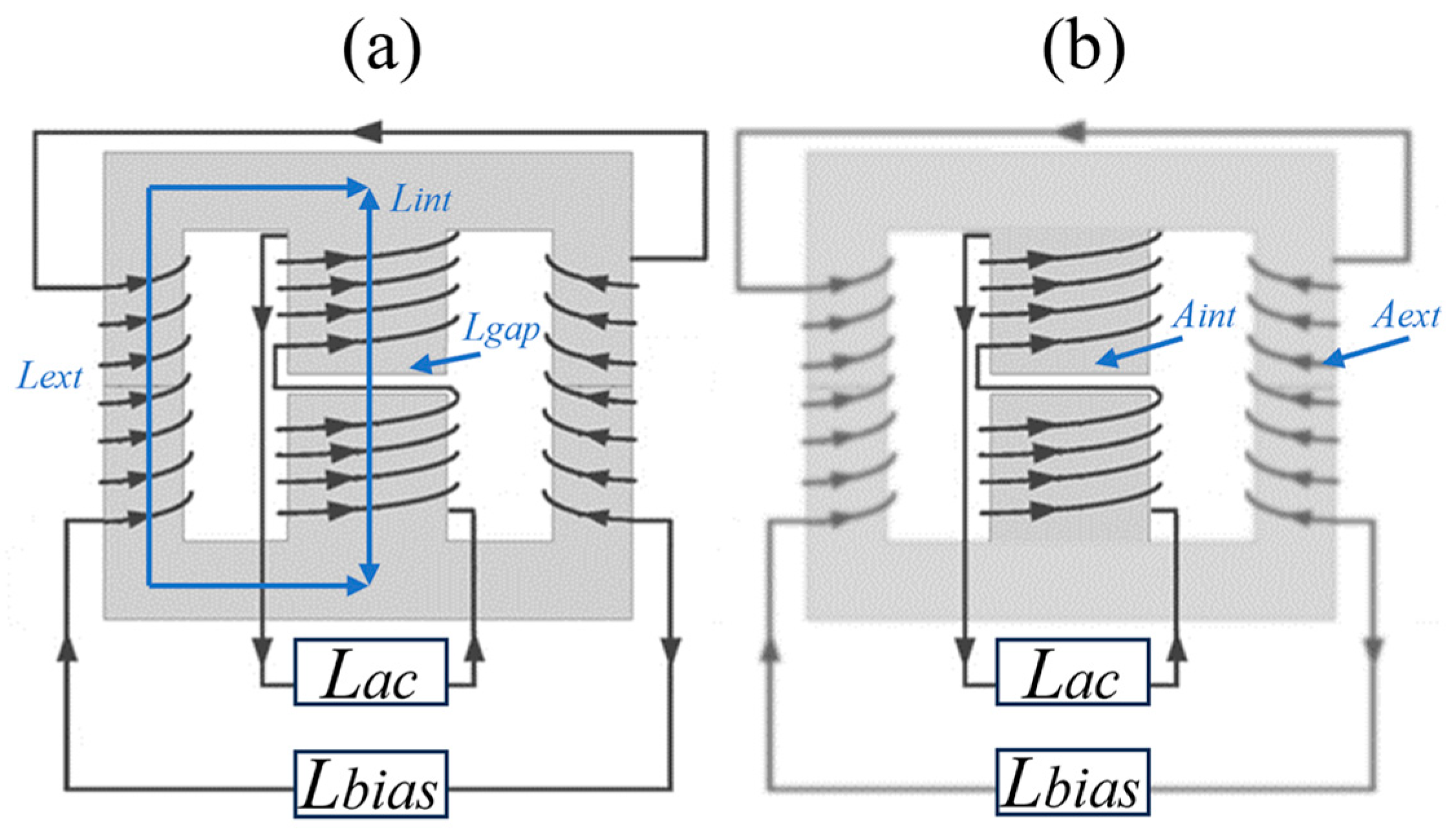
The design of a current-controlled variable inductor has its origins in prior studies [26]. Its operating principle involves saturating the outer part of the inductor core with direct current to vary the effective permeability. As shown in Figure 3, this inductor consists of two overlapped ferrite cores in the shape of an “E”. The central branch has an air gap and is wound to form the main inductor (Lac). On the other hand, the two side arms form the saturation control inductor (Lbias), which is wound in a series with opposite polarity to decouple Lac from Lbias, nullifying the influence of magnetic flux from the Lac winding and preventing induced voltages in Lbias.
For the design of this inductance, using the formula for inductance based on its geometry for an inductor with a ferrite core, the value of the inductance of the central branch is expressed as follows:
L i n t = μ 0 μ i A i n t ( n i n t ) 2 l i n t .
where μi is the initial permeability of the core, μ0 is the permeability of air, A i n t is the effective cross-sectional area of the central branch, n i n t is the number of turns in the Lac winding, and lint is the length of the central branch.
The value of the inductance due to the air gap is expressed by
L g a p = μ 0 A i n t ( n i n t ) 2 l g a p
where l g a p is the length of the air gap.
The leakage inductance represents the magnetic flux that closes through the air and not through the central body of the ferrite,
L l e a k a g e = μ 0 16 A i n t ( n i n t ) 2 l i n t
and the inductance of the two outer branches is given by
L e x t = 2 μ 0 μ ~ A e x t ( n i n t ) 2 l e x t
where μ ~ is the relative permeability without being subjected to DC bias.
Therefore, the following expression is used to calculate the maximum value of Lac:
1 L a c m a x = 1 L e x t + L l e a k a g e + 1 L i n t + 1 L g a p .
Because μ ~ decreases when exposed to continuous magnetic field intensity (Hbias), to which the Lbias winding is subjected, the relationship between L a c m a x and L a c m i n , with the second being the minimum value of Lac for the minimum μ ~ due to the maximum Hbias, can be obtained using the following expression:
L a c m a x L a c m i n = 2 μ e l i n t l e x t + l i n t μ ~ + 32 + μ e l i n t l e x t + l i n t μ i + 1 2 μ e l i n t l e x t + l i n t μ i + 32 + μ e l i n t l e x t + l i n t μ i + 1
where μe is the effective relative permeability of the core with a gap, from the elementary equation of an inductor:
L = μ 0 μ e A e n 2 l .
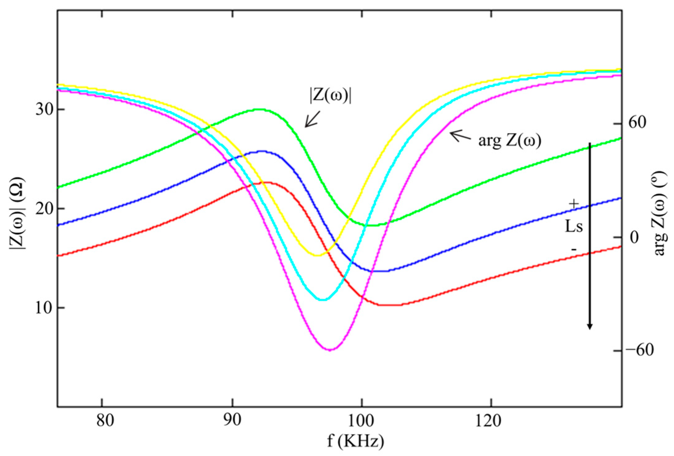
The effect of using this variable inductance in the Ls of the LLC circuit can be observed in Figure 4. If the operating point of the circuit is set near and above the series resonance frequency at the minimum impedance value, it can be observed how both the magnitude and phase of the impedance increase as the value of the series inductance is increased. This effect leads to two substantial advantages.
The first one is that for a fixed frequency, the inverter highest output current and power will occur at the point of minimum series inductance, where both the magnitude and phase of the impedance are minimized. However, when maximum output power is not required, the value of the series inductance can be increased to raise the magnitude of impedance, thereby reducing the output current.
The second advantage is that by varying both magnitude and phase, a better response to load changes is achieved, enabling the maintenance of ZVS even when working very close to the series resonance frequency. Previous studies, when operating with a fixed frequency near the series resonance frequency [4,18,24,27], showed poor inverter performance in response to load changes, leading to the loss of ZVS. In another previous study [28], a good response to load changes was achieved when working near the parallel resonance frequency because the input impedance was higher. However, this resulted in poorer optimization of reactive elements.
Therefore, working with a variable inductance adds a degree of freedom to the circuit, which, when combined with PS, allows for the optimization of the output current of the inverter.
These observations will be demonstrated both theoretically and experimentally later in the article.
Given that a ferrite core will be used for the high frequency LLC series inductance, and considering that induction heating applications operate with high input and output voltages [18], it is necessary to obtain the voltage across the series inductance ( V L s ) in order to calculate the magnetic flux density and avoid operating near the saturation point of the Lac core.
From the circuit analysis, the following equation is obtained:
V L s ω = V d ω V o ω
here, Vd(ω) and Vo(ω) represent the input and output voltages of the LLC circuit, respectively, with Vd(ω) lying within the range of
V d ω = V d ,     0 ω < π V d ,     π   ω < 2 π .
The voltage gain Hv(ω) is given by
H v ω = V o ω V d ω = Z ω j L s ω Z ω
and the phase difference between the voltages Vd(ω) and Vo(ω) is obtained from the argument
ϕ = arg H v ω .
Hence, through the integration of (16) and the subsequent solution of the equation, the expression for the voltage across the series inductor is formulated as follows:
V L s ω = V d ω 2 + n c o s ω ϕ ,     0 ω < π V d ω 2 n c o s ω ϕ ,     π   ω < 2 π
where n represents the voltage ratio
n = V p V d
for sufficiently large values of the quality factor Qp, the value of Vo(ω) is sinusoidal of the peak output voltage value Vp [24],
V o ω = V p s i n ω .
Ergo, the maximum value of the series inductor voltage is expressed as
V L s = V d π 2 + V p V d c o s π ϕ .
And the expression of the magnetic flux can be expressed as
B p k = 3 V L s 8 n i n t A e f   .
where
Ae is the effective area (m2);
f is the applied frequency (Hz).
As mentioned earlier, the operating point where the output power is maximized is when the value of the series inductance is minimized, thus saturating the outer branches of the inductor. At this point, the inductor voltage is at its highest, and therefore, the maximum flux density that the core can withstand is obtained under this assumption.
Considering the relationship B = µH and taking into account that the relative permeability of the core will change with exposure to Hbias to which the core will be subjected, the relationship between the maximum magnetic flux and the relative permeability for a constant magnetic field (H) is obtained [29].

4. LLC Resonant Inverter Design

4.1. Design Procedure

In the design procedures of the LLC inverter, the inductance value of the heating inductor (Lp) is typically provided from the geometric design parameters [30,31]. And the required power (Po), frequency, and quality factor is obtained from the heating time, penetration depth into the workpiece, and thermal treatment [32,33]. With these, the capacitance of the capacitor is adjusted to available values, considering its maximum voltage Vp, using
C p = 2 Q p P o ω V p 2 .
With the DC input voltage (Vd) of the inverter, the minimum value of the series inductance is calculated as
L S m i n = L a c m i n = 2 V d 2 π P o ω .
After obtaining the series inductor value, the switching frequency ( ω s w ) is adjusted to operate with a small phase angle by
α = a r c t a n 2 Q p ω s w ω o 4 Q p 2
then, the maximum voltage across the capacitor is recalculated using (25) and also the minimum series inductance (26).
The output current is obtained from
I r m s = V d 8 + π n 2 + 2 π n 2 c o s γ π L s ω s w
where the voltage phase γ represents the inverter commutation phase relative to the phase of the output voltage [24],
γ = π a r c s i n 1 n .
At this point a ferritic material is selected and the most restrictive value of the flux density is obtained. To do this, the core-loss curves at the operating frequency are compared with the obtained value of B = µH using the maximum permeability variation obtained from the relative permeability variation curves under DC bias.
Applying the effective area relationship for maximum flux density (24) to the winding area yields the expression for the area product as follows:
A p = A e A w = 3 V L s I r m s 8 B p k f s w J K
where
Ae is the effective area of the core given by the manufacturer;
J represents current density (A/m2), and in this case, when working with high-output currents from the inverter and aiming to minimize losses due to current carried in Lbias, only Lac is considered for the design since the Lbias winding will be negligible;
K is the fill factor, which will be assumed to have a value between 0.5 and 0.9.
Using the obtained value for the area product, a core size is selected to maintain a higher ratio, and the number of turns for Lac is calculated through
n i n t = 3 V L s 8 A e f s w B p k   .
With the number of turns and the characteristics of the selected core, using the equation (13), L a c m a x is calculated, and with the previous value of L a c m i n , the relationship between inductances is determined to obtain the necessary μ ~ from Equation (14). With this value and the curve on the datasheet regarding the relative permeability subjected to DC bias, the value of Hbias is determined to achieve the value of L a c m i n . If the L a c m i n value is not reached, iteration with a different ferritic material is performed. In the event of obtaining a value within the range, optimization is carried out to reduce the maximum DC current value (Ibias) of Lbias through the relationship given by
I b i a s 2 n e x t = H b i a s 2 l e x t
where
next represents the number of turns of an external branch;
lext is the length of the external branch from center to center of the core (m).
Table 1 presents the initial requirements for an annealing induction heating application [32], and also the results of applying the design procedure discussed earlier, where a ferrite core of N27 material with reference E 70/33/32 from TDK Electronics was ultimately selected.
The PS control technique involves shifting the switching phases of the two diagonals of the inverter with a phase angle (φ) ranging from 0 to π. Consequently, this modifies the voltage applied to the LLC resonant circuit, thereby affecting the output current and power of the inverter. Hence, by introducing this factor, the relationship between the input and output voltages of the circuit is now expressed as
n φ = n   c o s φ 2
and consequently, the phase between the output voltage of the inverter and the output voltage of the resonant circuit is obtained from
γ φ = π a r c s i n 1 n φ i f n φ > 1 a r c c o s φ π 2 n φ φ i f n φ 1  
where it has been considered that γ is dependent on φ to maintain soft switching [24] through the following inequality:
γ φ a r c c o s φ π 2 n φ φ .  
For controlling the output power of the inverter, it is considered that by combining the phase shift angle through PS control and the ability to vary the series inductance of the resonant circuit, power can be optimized by adjusting both the voltage applied to the resonant circuit and its impedance.
The equation for output power is expressed as a function of these two variables as follows:
P o φ , L s = V d 2 n φ s i n γ φ + φ + s i n γ φ L s ω s w
and the same operation is performed with the equation for the RMS value of the output current; thus,
I R M S φ , L s = V d π L s ω s w 4 cos φ + π n ( φ ) 2 + 2 π n φ c o s γ φ + φ + c o s ( γ φ ) + 4 .
A system of two equations and two variables is obtained. This system is used to find the optimal operating point for the inverter, ensuring that the output current remains minimized across the entire power range, thus reducing conduction, and switching losses in the transistors.

4.2. Losses Analysis

To verify the advantages of this optimization, the losses of the transistors of the inverter are mathematically analyzed to obtain the efficiency across the entire operating range [19], considering the right commutation to improve the power distribution of the transistors [34,35]. The losses due to the conduction current in each channel of the transistors are given by
P c d φ , L s = I r m s φ , L s 2 2 R D S o n
where R D S o n is the ON-state MOSFET channel resistance.
For switching energy losses, only the turn-OFF switching is considered, as the turn-ON switching will be negligible when operating in ZVS throughout the operating range. To calculate it, the polynomial equation of the turn-OFF switching loss curves from the manufacturer is obtained for the drain voltage equal to Vd and the gate resistance used. It is expressed as follows:
E o f f φ , L s = a I c φ , L s 2 + b I c φ , L s + c
where Ic is the switching current, and for the upper transistors, Q1 and Q4, it is derived from the following function:
I C Q 1 φ , L s = V d L s ω s w n φ cos γ + π φ 2
while the amplitude of the switching current for the lower transistors, Q2 and Q3, is given by
I C Q 3 φ , L s = V d L s ω s w n φ cos γ + φ + π φ 2 .
Therefore, the power losses for each transistor are obtained from
P s w φ , L s = E o f f φ , L s ω s w 2 π .
The losses due to the transistor gate depend on the total gate charge QG and the gate-to-source voltage VG, related through the following expression:
P g a t e = Q G V G ω s w 2 π .
On the other hand, the inductor core losses are due to the magnetic flux density, and the influence of the DC bias is negligible [26,36]; therefore, they can be obtained using the following equation:
P c o r e φ , L s = P v V e
where Pv is the core-loss density of the inductor given by the manufacturer for the operating frequency and magnetic flux density, and Ve is its volume.
As a final consideration, for the copper losses Pwire of the inductor, it is necessary to know the effective resistance of the winding Rcopper, taking into account the conductivity, the total length, and the skin effect using
P w i r e φ , L s = I R M S 2 R c o p p e r .
To conclude, the total losses are determined by the following equation:
P t o t φ , L s = 4 P c d φ , L s + 2 P s w Q 1 φ , L s + P s w Q 3 φ , L s + 4 P g a t e + P c o r e φ , L s + P w i r e φ , L s
meanwhile, the efficiency is given by
η φ , L s = P o φ , L s P o φ , L s + P t o t φ , L s .
For the losses analysis, the SiC MOSFET G320MT12K was used as the transistor for each of the inverter switches. Table 2 presents the characteristics obtained from the datasheet for the efficiency analysis of the inverter.
Considering (36), Figure 5 represents the entire possible operating range, for both the phase shift and series inductance variation, expressed as a function of the inverter output power. In the figure, there is a red dotted curve that results from optimizing the output current of the inverter. Therefore, this is the optimal operating point for control, where the losses in the inverter will be minimized. Following the path of the curve, it can be observed that at high-output powers, the increase in series inductance value is prioritized over increasing the phase shift. This is because reducing the output current is achieved by increasing the input circuit impedance and, when switched with a small phase shift, for the same output current, the switching current is lower. However, when a lower output power is demanded, working with a higher series inductance value, which implies a greater input impedance, this results in applying a lower voltage through a larger phase shift. This enables switching with smaller angles and counteracts the effect of the increased phase between voltage and output current due to the elevated series inductance value.
To illustrate the difference in efficiency when operating across the entire power range using only PS control, as opposed to including variable inductance VI-PS, the efficiency and output current of both approaches have been compared as a function of power in Figure 6. The starting point for both controls is the same and corresponds to the maximum power value because, in both controls, at that point, the phase shift is minimized, and in the control with the variable inductor, the inductance is set to the minimum value, which is the same value maintained by PS control across its entire power range. As seen in the figure, the improvement in efficiency occurs as the inverter output power decreases because the output RMS current is reduced. This allows for maintaining a performance above 98.5% across the entire operating range and even reaching 99% when the output current is significantly reduced.
Table 3 shows the breakdown of the losses for the optimization of the VI-PS control compared to the PS control operating at 12 kW.

4.3. Control Principles

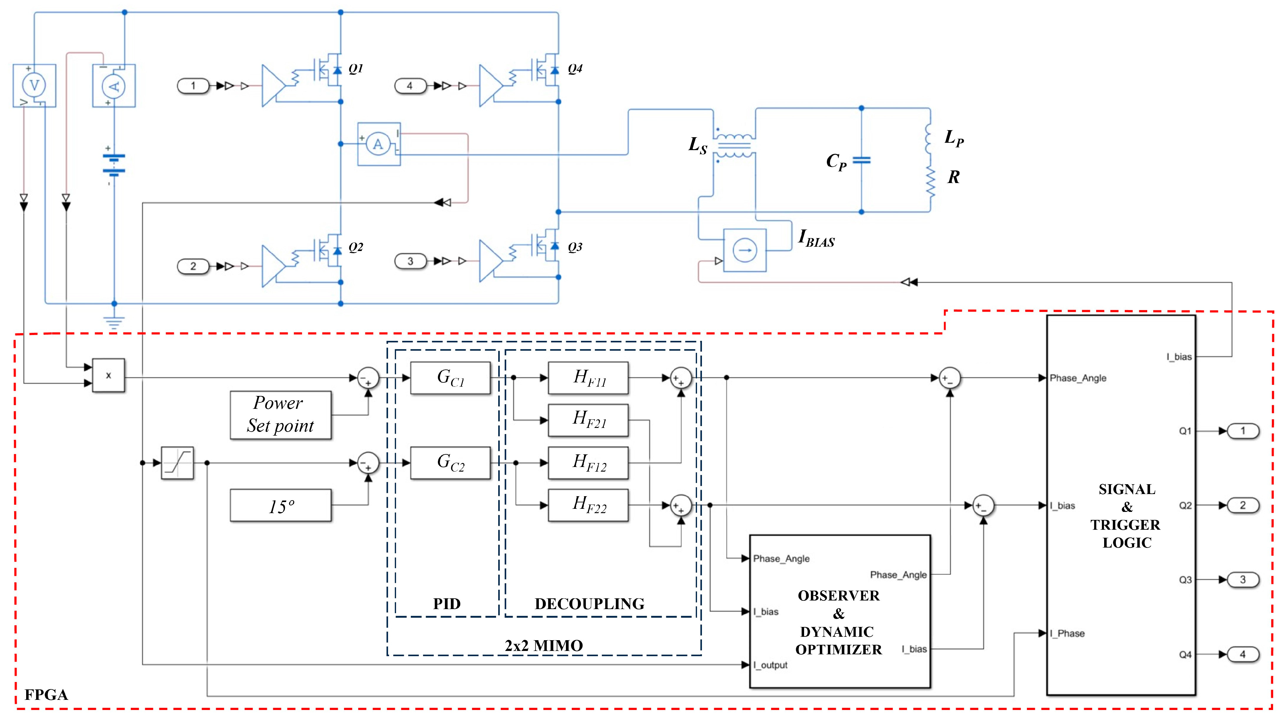
The simplified VI-PS control scheme is depicted in Figure 7. Due to its multivariable nature, a Multiple Inputs Multiple Outputs (MIMO) system is employed, which is nonlinear and coupled. It is solved using a Proportional Integral Differential (PID) control and a decoupled diagonalization network [37,38]. This configuration enables the manipulation of one variable to affect the other and vice versa, generating a control loop that iterates between them. The system inputs include the input power of the inverter compared with the selected reference, and the phase angle α between the output voltage and current of the inverter, which is fixed at 15°, as defined in Equation (27). Consequently, the output variables are the phase angle φ of the phase shift control (PS) and the direct current (Ibias) of the Lbias winding.
Furthermore, a digital observer with a dynamic optimizer is employed to reduce the RMS value of the inverter output current [39]. In this block, by measuring the inverter output current and comparing it with the values of the phase shift angle and Ibias, interventions are made in the outputs to optimize both values. This ensures the inverter operates within the optimal operating range, as represented by the red dashed line in Figure 5. The signal conditioning and triggering logic block, besides generating the triggering signals of the transistors with the corresponding dead times based on the phase shift angle value received from the system, compares the zero-crossings of the current in each cycle to ensure ZVS during switching. If, during the heating process, the angle α shifts significantly, approaching the capacitive region due to changes in the inductance of Lp, modified due to changes in permeability, electrical conductivity of the material, or due to a load jump caused by coupling and decoupling the piece in the inductor, the control system directly decreases the Ibias current to increase the value of Ls. This adjustment maintains soft switching, preventing over-voltages or over-currents at the inverter output. Although the variable inductor has been designed to work far from the saturation limits, in case where the inductor becomes saturated, the angle α would be reduced, as seen in Figure 4; this will also be detected in this part of the control, decreasing the bias current to avoid saturation.

5. Experimental Results with Discussions

To conduct the experimental tests discussed in this section, the variable inductance design was first evaluated. The result is shown in Figure 8, which shows the calculated and experimentally measured value of the inductance as a function of the bias current.
As can be seen in Figure 8, there is a dispersion between the calculated value and the experimentally measured value. This deviation is mainly due to the range of dispersion of the initial permeability provided by the manufacturers and its dependence on temperature. Nevertheless, it can be seen that the mathematical model well describes the behavior of the variable detector as a function of the bias current.
A 20 kW induction heating inverter module was used to test the complete design. This module includes FPGA-based control, sigma–delta modulator sensing stages, isolated power sources, a controllable current source based on the Howland current pump with an OPA548 as a high-current operational amplifier, trigger drivers, transistors, and a water cooler heatsink. The inverter is powered by a 500 VDC supply.
The test bench that was used is shown in Figure 9, and it has been assembled with the design components from Section 4. Each number corresponds to the following:
(1)
Induction heating inverter with four SiC G3R20MT12K;
(2)
300 MHz bandwidth DSO;
(3)
Differential voltage probe and Rogowski current probe;
(4)
Hall effect probe for DC bias current;
(5)
Controllable series inductor (Ls);
(6)
Parallel capacitor (Cp);
(7)
Parallel inductor (Lp);
(8)
Water-cooled load.
Figure 9. Inverter with LLC resonant load test bench. The numbered labels describe the components on the bottom.
Electronics 13 02593 g009
To validate the design, the theoretical values obtained from the equations were compared with the measurements made on the inverter at two power levels. The result is shown in Table 4, where a small dispersion is observed due to the modeling method used and the existence of parasitic elements and losses of other elements are not taken into account in the calculation, such as conductors, connections, temperature dependence components, and the error of the measurement system, voltage, and current sensors.
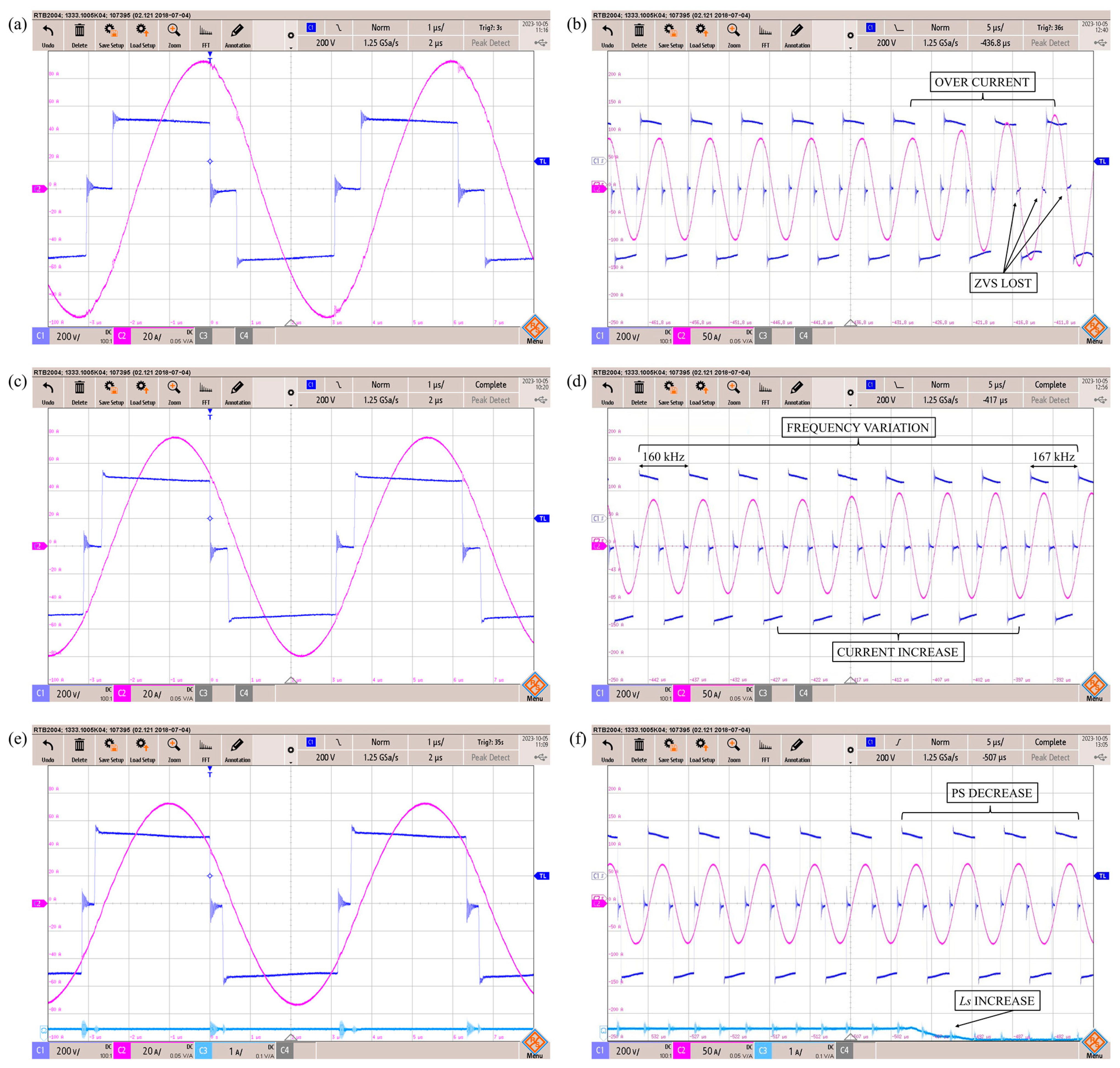
Figure 10 displays oscillograms captured by the DSO for the inverter operating at 60% power with three different control techniques and their response to load changes by rapidly extracting the load from the inductor. The first control strategy is fixed frequency, using the PS control. The second control strategy involves a narrow frequency range, combining frequency modulation with a phase shift (FM-PS). The third strategy, analyzed in this article, is fixed frequency VI-PS control. In all three cases, the LLC resonant circuit remains the same, with the minimum series inductance value. In terms of performance with the same power setpoint, as depicted in the figure, the PS control has been configured at a higher frequency than the resonant design. This adjustment is necessary to operate above the series resonance frequency, ensuring an adequate operating range for the commutation phase α and enabling soft switching [13]. Consequently, for the same power level, the inverter output current is higher with PS control, reaching 64 ARMS, compared to the other control techniques. In the case of the FM-PS control, the output current of 56 ARMS is slightly higher than that of the VI-PS control. Despite being able to maintain the same phase angle α of 15°, the frequency is higher due to regulation [12,19], and it commutates with a wider phase shift φ, leading to increased switching losses due to the higher current amplitude during OFF switching compared to the VI-PS control. On the other hand, the VI-PS control maintains a closed-phase shift by desaturating the series inductance, allowing for a lower output current of 50 ARMS, and switching with less current due to a narrower φ angle, while maintaining the 15° phase angle α, and a lower frequency closer to the series resonance frequency.
As observed in the load changes behavior, the PS control, despite operating at a higher frequency with increased circuit input impedance and phase angle α, fails to maintain ZVS behavior and control over-current despite widening the phase shift angle. Meanwhile, FM-PS control manages to maintain ZVS behavior but at the cost of a sudden frequency variation of 8 kHz, a complex issue to handle in terms of harmonic filtering. Furthermore, it is observed that the current increases slightly despite the control correction, increasing the angle α width. This effect could be mitigated by allowing the control to increase the frequency even further. Lastly, as shown in the VI-PS control oscillogram, soft switching is preserved, and the over-current caused by the load jump is controlled. This is achieved by rapidly desaturating the external branches of inductor Ls, causing the impedance difference from the load jump to attenuate due to the increased impedance resulting from a higher series inductance in the LLC resonant circuit. It is observed that the change in impedance by increasing Ls is so effective that the control has to decrease the angle to maintain the current level, in contrast to the other two control techniques.
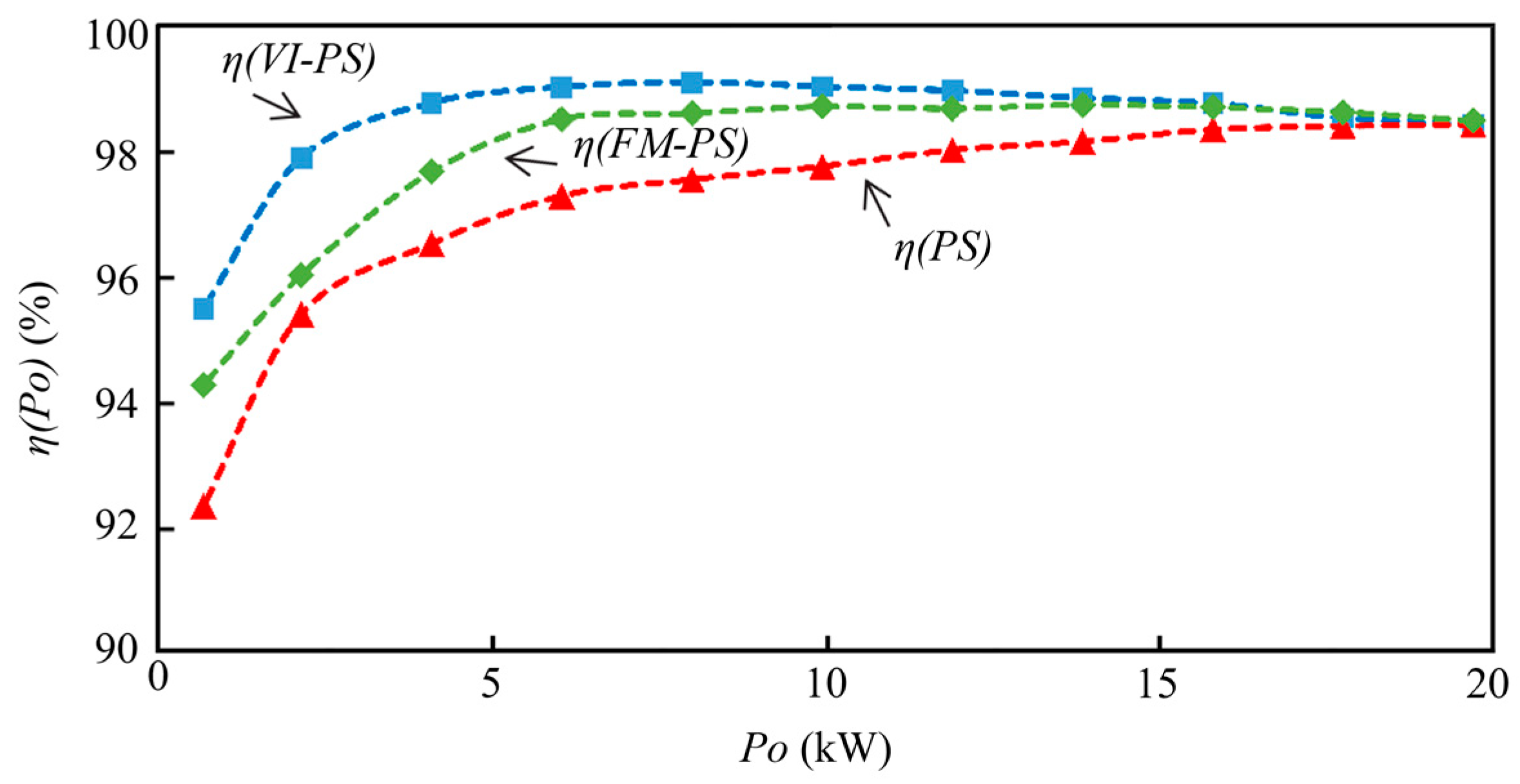
Finally, to conclude the comparison between the three control types and validate the design discussed in the article, the inverter efficiency has been measured across the entire power range by the difference of the input power measured directly at the input DC voltage supply and the output power measured by the DSO measurement of the principal value of the instantaneous multiplication of the output voltage and current of the inverter bridge [24], starting from the same frequency and phase shift angle, with the minimum series inductance. As shown in Figure 11, at the starting point, all three controls achieve the same performance. However, as the power decreases, the VI-PS control gradually increases its efficiency, as explained earlier in Section 4. In this figure, in comparison to the theoretical calculation in Figure 6, the measurement for the FM-PS control has been added. Despite maintaining similar performance to the variable inductance control, FM-PS has the disadvantage of losing reactive element optimization. This occurs as the frequency increases with a lower power demand, leading to poorer efficiency and a more complex harmonic filtering. It is crucial to note that in the PS control, in order to handle load jumps or changes in the permeability of the heating inductor, the frequency should be increased, resulting in lower efficiency. As observed in the figure, the measurements closely align with the theoretically calculated values, despite the dispersion in real components and the losses not being accounted for in the theoretical calculation.

6. Conclusions

This article explores the combined effect of variable inductance control with phase shift VI-PS. It analyzes and proposes a design for the variable inductance and the LLC resonant circuit for a high-frequency application in induction heating annealing. The study provides an analysis of the optimal control strategy, reducing the output current, maximizing efficiency across the entire power range, and maintaining ZVS operation even with significant load changes.
The proposed control technique has been implemented in a 20 kW full-bridge inverter using SiC MOSFETs with an LLC resonant load. The experimental results have been validated against theoretical predictions and compared experimentally with two traditional phase shift control techniques: fixed-frequency and narrow-frequency-range control. The comparison was conducted at the same power level, comparing conduction losses in the MOSFET channels and losses due to OFF switching. The behavior for over-currents and soft switching during load jumps was also compared. Both tests were conducted using the same LLC resonant circuit.
Ultimately, it has been demonstrated that at different output power levels, the VI-PS control technique achieves superior efficiencies across the entire operating range compared to traditional control methods. It can maintain efficiency above 98.5% and operate with load jumps while keeping ZVS functionality.
Therefore, this article introduces a novel VI-PS control technique which, by using a variable inductor and a phase shift, achieves higher efficiency over the whole operating range. This is because it allows operation at a fixed frequency close to the series resonance frequency, setting a low-switching angle and reducing the output current value. It also allows operation over a wide range of loads while maintaining ZVS switching. Consequently, this work opens the way for future research on the fixed-frequency control of inverters for induction heating by controlling the reactive elements, whether in two-element, three-element, or multi-element resonant tanks, thus enabling improved efficiency and load range.

Author Contributions

Conceptualization, J.L.B.; Methodology, J.L.B.; Software, J.L.B. and J.J.; Validation, J.L.B. and V.E.; Investigation, J.L.B.; Resources, V.E.; Data curation, V.E. and J.J.; Writing—original draft, J.L.B.; Supervision, J.L.B. All authors have read and agreed to the published version of the manuscript.

Funding

This research received no external funding.

Data Availability Statement

Data are contained within the article.

Conflicts of Interest

Author Juan L. Bellido was employed by the company SiCtech Induction. The remaining authors declare that the research was conducted in the absence of any commercial or financial relationships that could be construed as a potential conflict of interest.

References

  1. Lucia, O.; Maussion, P.; Dede, E.J.; Burdio, J.M. Induction heating technology and its applications: Past developments, current technology, and future challenges. IEEE Trans. Ind. Electron. 2014, 61, 2509–2520. [Google Scholar] [CrossRef]
  2. Grajales, L.; Sabaté, J.A.; Wang, K.R.; Tabisz, W.A.; Lee, F.C. Design of a 10 kW, 500 kHz phase-shift controlled series-resonant inverter for induction heating. In Proceedings of the Conference Record of the 1993 IEEE Industry Applications Conference Twenty-Eighth IAS Annual Meeting, Toronto, ON, Canada, 2–8 October 1993; pp. 843–849. [Google Scholar]
  3. Kamli, M.; Yamamoto, S.; Abe, M. A 50-150 kHz Half-Bridge inverter for induction heating Application. IEEE Trans. Ind. Electron. 1996, 43, 163–172. [Google Scholar] [CrossRef]
  4. Burdío, J.M.; Barragán, L.A.; Monterde, F.; Navarro, D.; Acero, J. Asymmetrical voltage-cancellation control for full-bridge series resonant inverters. IEEE Trans. Power Electron. 2004, 19, 461–469. [Google Scholar] [CrossRef]
  5. Esteve, V.; Bellido, J.L.; Jordán, J. Optimal Design of a Single-Phase Bidirectional Rectifier. Energies 2024, 17, 1280. [Google Scholar] [CrossRef]
  6. Esteve, V.; Bellido, J.L.; Jordán, J.; Dede, E.J. Improving the Efficiency of an Isolated Bidirectional Dual Active Bridge DC–DC Converter Using Variable Frequency. Electronics 2024, 13, 294. [Google Scholar] [CrossRef]
  7. Ahmed, N. High frequency soft switching AC conversion circuit with dual mode PWM/PDM control strategy for high power IH applications. IEEE Trans. Ind. Electron. 2011, 58, 1440–1448. [Google Scholar] [CrossRef]
  8. Ramalingam, S.R.; Boopathi, C.S.; Ramasamy, S.; Ahsan, M.; Haider, J.; Shahjalal, M. A Single-Coil Multi-Tapped PDM-Based Induction Heating System for Domestic Applications. Electronics 2023, 12, 404. [Google Scholar] [CrossRef]
  9. Grajales, L.; Lee, F.C. Control system design and small-signal analysis of a phase-shift controlled series-resonant inverter for induction heating. In Proceedings of the PESC ‘95—Power Electronics Specialist Conference, Atlanta, GA, USA, 18–22 June 1995; pp. 450–456. [Google Scholar]
  10. Dudrik, J.; Trip, N.-D. Soft-switching PS-PWM DC–DC converter for full-load range applications. IEEE Trans. Ind. Electron. 2010, 57, 2807–2814. [Google Scholar] [CrossRef]
  11. Viriya, P.; Thomas, T. Power transfer characteristics of a phase-shift controlled ZVS inverter for the application of induction heating. In Proceedings of the International Power Electronics Conference (IPEC), Tokyo, Japan, 3–7 April 2000; pp. 423–428. [Google Scholar]
  12. Showybul, S.M.; Shakib, I.; Mekhilef, S. A frequency adaptive phase shift modulation control-based LLC series resonant converter for wide input voltage applications. IEEE Trans. Power Electron. 2017, 32, 8360–8370. [Google Scholar]
  13. Burdío, J.M.; Canales, F.; Barbosa, P.M.; Lee, F.C. A comparison study of fixed-frequency control strategies for ZVS dc/dc series resonant conveters. In Proceedings of the 2001 IEEE 32nd Annual Power Electronics Specialists Conference (IEEE Cat. No.01CH37230), Vancouver, BC, Canada, 17–21 June 2001; pp. 427–432. [Google Scholar]
  14. Yang, X.; Sha, D. Automatic Current Limit Strategy for LLC DC-DC Converter for Overload Operation. EEE Trans. Power Electron. 2024, 39, 9917–9928. [Google Scholar] [CrossRef]
  15. Scirè, D.; Lullo, G.; Vitale, G. Non-Linear Inductor Models Comparison for Switched-Mode Power Supplies Applications. Electronics 2022, 11, 2472. [Google Scholar] [CrossRef]
  16. Scirè, D.; Lullo, G.; Vitale, G. Design and Modeling of an Interleaving Boost Converter with Quasi-Saturated Inductors for Electric Vehicles. In Proceedings of the 2020 AEIT International Conference of Electrical and Electronic Technologies for Automotive (AEIT AUTOMOTIVE), Turin, Italy, 18–20 November 2020; pp. 1–6. [Google Scholar] [CrossRef]
  17. Chudjuarjeen, S.; Sangswang, A.; Koompai, C. An improved LLC resonant inverter for induction-heating applications with asymmetrical control. IEEE Trans. Ind. Electron. 2011, 58, 2915–2925. [Google Scholar] [CrossRef]
  18. Espí, J.M.; Dede, E.J.; García-Gil, R.; Castelló, J. Design of the L-LC resonant inverter for induction heating based on its equivalent SRI. IEEE Trans. Ind. Electron. 2007, 54, 3178–3187. [Google Scholar] [CrossRef]
  19. Lucía, O.; Burdío, J.M.; Millán, I.; Acero, J.; Barragán, L.A. Efficiency oriented design of ZVS half-bridge series resonant inverter with variable frequency duty cycle control. IEEE Trans. Power Electron. 2010, 25, 1671–1674. [Google Scholar] [CrossRef]
  20. Dede, E.; Gonzalez, J.; Linares, J.; Jordan, J.; Ramirez, D.; Rueda, P. 25-kW/50-kHz generator for induction heating. IEEE Trans. Ind. Electron. 1991, 38, 203–209. [Google Scholar] [CrossRef]
  21. Lucía, O.; Burdío, J.M.; Millán, I.; Acero, J.; Puyal, D. Load-adaptive control algorithm of half-bridge series resonant inverter for domestic induction heating. IEEE Trans. Ind. Electron. 2009, 56, 3106–3116. [Google Scholar] [CrossRef]
  22. Czarkowski, D.; Kazimierczuk, M.K. Phase-controlled series-parallel resonant converter. IEEE Trans. Power Electron. 1993, 8, 309–319. [Google Scholar] [CrossRef]
  23. Barragán, L.A.; Navarro, D.; Acero, J.; Urriza, I.; Burdío, J.M. FPGA implementation of a switching frequency modulation circuit for emi reduction in resonant inverters for induction heating appliances. IEEE Trans. Ind. Electron. 2008, 55, 11–20. [Google Scholar] [CrossRef]
  24. Esteve, V.; Jordan, J.; Dede, E.J.; Sanchis-Kilders, E.; Martinez, P.J.; Maset, E.; Gilabert, D. Optimal LLC inverter design with SiC MOSFETs and phase shift control for induction heating applications. IEEE Trans. Ind. Electron. 2022, 69, 11100–11111. [Google Scholar] [CrossRef]
  25. Sewell, H.I.; Stone, D.A.; Bingham, C.M. Dynamic load impedance matching for induction heater systems. COMPEL 2003, 22, 30. [Google Scholar] [CrossRef]
  26. Medini, D.; Ben-Yaakov, S. A current-controlled variable-inductor for high frequency resonant power circuits. In Proceedings of the 1994 IEEE Applied Power Electronics Conference and Exposition—ASPEC’94, Orlando, FL, USA, 13–17 February 1994. [Google Scholar]
  27. Ngo-Phi, T.; Nguyen-Quang, N. LLC inverter design procedure for induction heating with quantitative analysis of power transfer. Vnuhcm J. Eng. Technol. 2021, 4, 738–746. [Google Scholar]
  28. Esteve, V.; Jordán, J.; Dede, E.J.; Martinez, P.J.; Ferrara, K.J.; Bellido, J.L. Comparative analysis and improved design of LLC inverters for induction heating. IET Power Electron. 2023, 16, 1754–1764. [Google Scholar] [CrossRef]
  29. Wilson, P.R. Modelling and Simulation of Magnetic Components in Electric Circuits. Ph.D. Thesis, Dept. Elect. Comput. Eng., Univ. Southampton, Southampton, UK, November 2001. [Google Scholar]
  30. Wheeler, H.A. Discussion on simple inductance formulas for radio coils. Proc. Inst. Radio Eng. 1929, 17, 580–582. [Google Scholar]
  31. Wheeler, H.A. Inductance formulas for circular and square coils. Proc. IEEE 1982, 70, 1449–1450. [Google Scholar] [CrossRef]
  32. Rudnev, V.; Loveless, D.; Cook, R.; Black, M. Hand Book of Induction Heating; CRC Press: Boca Raton, FL, USA, 2017. [Google Scholar]
  33. Brown, G.H.; Hoyler, C.N.; Bierwirth, R.A. Theory and Application of Radio-Frequency Heating; Van Nostrand: New York, NY, USA, 1947. [Google Scholar]
  34. Esteve, V.; Jordan, J.; Sanchis-Kilders, E.; Dede, E.J.; Maset, E.; Ejea, J.B.; Ferreres, A. Improving the reliability of series resonant inverters for induction heating applications. IEEE Trans. Ind. Electron. 2014, 61, 2564–2572. [Google Scholar] [CrossRef]
  35. Esteve, V.; Jordán, J.; Dede, E.J.; Bellido, J.L. Enhanced asymmetrical modulation for half-bridge series resonant inverters in induction heating applications. IET Power Electron. 2023, 16, 2482–2491. [Google Scholar] [CrossRef]
  36. Alonso, J.M.; Perdigão, M.S.; Vaquero, D.G.; Calleja, A.J.; Saraiva, E.S. Analysis, design, and experimentation on constant-frequency DC-DC resonant converters with magnetic control. IEEE Trans. Power Electron. 2012, 27, 1369–1382. [Google Scholar] [CrossRef]
  37. Rapoport, E.; Pleshivteva, Y. Optimal Control of Induction Heating Process; CRC Press: Boca Raton, FL, USA, 2006. [Google Scholar]
  38. O’Reilly, J. Multivariable Control for Industrial Applications; Peter Peregrinus Ltd.: London, UK, 1987. [Google Scholar]
  39. Boubaker, O.; Zhu, Q.; Mahmoud, M.S. New Trends in Observer-Based Control: A Practical Guide to Process and Engineering Applications; Academic Press: Cambridge, MA, USA, 2019. [Google Scholar]
Figure 1. Parallel LLC resonant circuit.
Electronics 13 02593 g001
Figure 2. Simulation of magnitude of impedance (red) and phase of impedance (blue) of the parallel LLC resonant circuit.
Electronics 13 02593 g002
Figure 3. Structure of the current-controlled variable inductor: (a) corresponds to zero bias current and (b) corresponds to maximum bias current.
Electronics 13 02593 g003
Figure 4. Simulated magnitude of impedance (green, blue, and red) and phase of impedance (yellow, light blue, and magenta) are arranged in descending order of the Ls values of the LLC parallel resonant circuit.
Electronics 13 02593 g004
Figure 5. Phase shift and variable inductor as a function of the output power. The red dotted curve corresponds to the optimal control strategy.
Electronics 13 02593 g005
Figure 6. Evolution of the efficiency and output current of the inverter as a function of the output power.
Electronics 13 02593 g006
Figure 7. Schematic of the proposed system, detailing the inverter topology, the resonant load LLC with the variable inductor, and the control diagram.
Electronics 13 02593 g007
Figure 8. Calculated and measured behavior of the variable inductor due to bias current.
Electronics 13 02593 g008
Figure 10. Oscillograms of experimental tests of the LLC inverter with different control strategies: (a,b) with PS, (c,d) with FM-PS, and (e,f) with VI-PS. Figures (a,c,e) correspond to operation at 60% power, and (b,d,f) show the response to a load change at that power level. C1 (dark blue) represents the output voltage (200 V/div), C2 (magenta) shows the output current (20 A/div) in figures (a,c,e) and (50 A/div) in (b,d,f). C3 (light blue) shows the DC bias current (1 A/div) of Ls in (e,f). The time base is 1 µs/div in (a,c,e) and 5 µs/div in (b,d,f).
Electronics 13 02593 g010
Figure 11. Results of experimental measurements of the inverter efficiency across the entire power range.
Electronics 13 02593 g011
Table 1. Initial requirements and results of the design.
MagnitudeSymb.Eq.ValueUnit
Output powerPo(36)20kW
Quality factorQp(3)10
Switching frequencyfsw(27)157kHz
DC input voltageVd(17)500V
Parallel inductorLp(1)2µH
Parallel capacitorCp(25)0.66µF
Minimun series inductor L s m i n L a c m i n (26)8µH
Maximun series inductor L s m a x L a c m a x (13)14.5µH
Table 2. Transistor characteristics.
MagnitudeSymb.Eq.ValueUnit
On resistance R D S o n (38)17mΩ
Turn-OFF lossesa(39)0.0268µJ/A2
b0.2679µJ/A
c18.929µJ
Gate chargeQG(43)180nC
Table 3. Losses results for 12 kW operation power.
MagnitudeSymb.Eq.PSVI&PSUnit
Conduction losses P c d (38)45.6118.478W
Switching losses P s w Q 1 (42)3.4657.783W
Switching losses P s w Q 3 3.2386.075W
Gate losses P g a t e (43)0.5080.508W
Inductor core losses P c o r e (44)3.576.12W
Inductor wire losses P w i r e   (45)15.4996.279W
Total losses P t o t (46)216.952116.065W
Table 4. Comparison of theoretical and measured results.
MagnitudeSymb.12 kW20 kWUnit
Theor.Meas.Theor.Meas.
Phase angle α 1515.11514.8°
Voltage phase γ 52.451.839.440.7°
Output current I R M S 46.649.583.585.1A
Upper transistors current I C Q 1 39.24055.155.6A
Lower transistors current I C Q 3 38.638.354.353.7A
Disclaimer/Publisher’s Note: The statements, opinions and data contained in all publications are solely those of the individual author(s) and contributor(s) and not of MDPI and/or the editor(s). MDPI and/or the editor(s) disclaim responsibility for any injury to people or property resulting from any ideas, methods, instructions or products referred to in the content.