Article

Optimization of Contact Resistance and DC Characteristics for AlGaN/GaN HEMTs Utilizing Sub-10 nm Nanohole Etching

by
Hsin-Jung Lee
1,*,
Cheng-Che Lee
1,
Hong-Ru Pan
1 and
Chieh-Hsiung Kuan
1,2
1
Graduate Institute of Electronics Engineering, National Taiwan University, Taipei 10617, Taiwan
2
Graduate Institute of Photonics and Optoelectronics, National Taiwan University, Taipei 10617, Taiwan
*
Author to whom correspondence should be addressed.
Electronics 2024, 13(13), 2490; https://doi.org/10.3390/electronics13132490
Submission received: 11 March 2024 / Revised: 19 June 2024 / Accepted: 20 June 2024 / Published: 25 June 2024

Abstract

:
In this paper, the contact resistance of AlGaN/GaN high electron mobility transistor (HEMT) was improved by introducing nanoscale hole arrays in ohmic regions, and the DC characteristics of the conventional structure and nanohole etching structure for HEMTs were measured for comparison. Sub-10 nm nanoholes were patterned on the ohmic area surface of AlGaN using electron beam lithography and a low-temperature short-time development. Various dwell times of e-beam exposure from 5 to 30 μs were investigated and the corresponding contact resistance of the nano hole etching structure and planar structure were compared by the transmission line model (TLM) method. We observed a reduced contact resistance from 1.82 to 0.47 Ω-mm by performing a dwell time of 5 μs of exposure for nanohole formation compared to the conventional structure. Furthermore, the DC characteristics demonstrate that the maximum drain current for HEMTs was enhanced from 319 to 496 mA/mm by utilizing this optimized ohmic contact. These results show that devices with sub-10 nm nanohole ohmic contacts exhibit an improved contact resistance over the conventional structure, optimizing device performance for HEMTs, including a lower on-resistance and higher maximum drain current.

1. Introduction

AlGaN/GaN HEMT, one of the representative structured transistors in the third-generation semiconductor technology, provides many advantageous properties over silicon technology, such as a large critical electric field, high electron mobility, high saturation current, and an excellent temperature capability [1,2,3,4], due to its wide band gap and two-dimension electron gas (2DEG) density. Such outstanding performance makes the HEMT device a highly anticipated candidate in future high-power and high-frequency applications [5,6,7,8].
Low contact resistance is vital for HEMTs and ensures that the device meets the desired performance, including a high current density, low on-resistance, lower resistance heating, and low power loss, particularly regarding power electronics and high-frequency applications [9,10]. For RF devices, frequency characteristics are related to the connect resistance and transconductance in transistors [11]. For power devices, the low channel resistance of the on-state is essential to reduce the power device loss, which is strongly correlated with the series resistance induced by ohmic contacts [12]. To reduce the contact resistance of GaN-based HEMTs, various metallization stacks have been proposed for ohmic contact such as Ti/Al/Ti/Au, Ti/Al/Ni/Au, Ti/Al/Mo/Au, and Ti/Au/Al/Ni/Au [13,14,15,16]. Performing ion implantation to dope source and drain regions has also been found to be an effective strategy to reduce contact resistance [17]. To achieve a low contact resistance and high-frequency characteristics, a regrown n+ GaN contact with Si doping on the ohmic region has been demonstrated with a contact resistance of 0.16 Ω-mm [18]. However, reducing resistance for GaN devices is still challenging because of the complex fabrication process and the high annealed temperature required for doping techniques. In recent years, a new structure incorporating etching patterns in the ohmic area was proposed to reduce ohmic contact resistance. In 2015, Takei et al. proposed an uneven AlGaN structure to reduce ohmic contact resistance on HEMTs. Through 2D device simulations, an increase in 2DEG concentration can be observed near the edge regions of the uneven AlGaN structure due to the fringing effect [19]. They experimentally confirm that lower contact resistance can be achieved by introducing ohmic contacts with uneven structures.
In general, an increase in the thickness of the AlGaN layer in AlGaN/GaN HEMTs leads to an enhancement in the sheet carrier density of the 2DEG in the GaN channel. This enhancement subsequently results in a decrease in the contact resistance associated with the 2DEG (Rc2DEG) [20]. However, a thicker AlGaN layer also contributes to an increase in the contact resistance of the AlGaN layer itself (RcAlGaN), thereby elevating the overall contact resistance. Consequently, an optimal thickness range for the AlGaN layer, typically between 10 and 25 nm [21], is essential for AlGaN/GaN HEMTs. By implementing an uneven AlGaN structure in ohmic regions characterized by various etching patterns, this inherent trade-off regarding the AlGaN layer thickness can be effectively mitigated compared to conventional flat AlGaN structures. To analyze the effect of pattern size on device performance, Wang et al. fabricated HEMT devices with patterned etching holes with apertures of 0.8, 1.6, and 3 μm [22], and found that 0.8 μm exhibited the lowest contact resistance. It can be explained by forming more side areas on the surface of AlGaN and N-vacancies, which enhances the tunneling current and reduces the contact resistance between the AlGaN and electrodes. Benakaprasad et al. performed extensive investigation on contact resistance and surface roughness with varying parameters including etching pattern, etching depth, annealed temperature, and a planar/nonplanar ohmic metallization [23]. You et al. investigated the influence of different recess hole array arrangements on ohmic contact and found that the device with a gradually increasing hole pattern of 1/3/5 μm demonstrates a superior improvement in contact resistance [24]. To enhance the frequency characteristics, Lee et al. recently fabricated AlGaN/GaN HEMTs with 1 μm line ohmic etching patterns and optimized the RF performance for Ka-band applications [25].
In contrast to the studies mentioned above that utilized microscale patterned uneven structures, this work introduces the technique of sub-10 nm nanohole etching within the ohmic region to reduce contact resistance for HEMTs. The nanohole etching pattern was designed with dimensions smaller than 20 nm, which aims to ensure that the hole sizes are smaller than the spacing between interface traps. These interface traps, with a density of 1012 eV−1cm−2 [26], generally arise from threading dislocations caused by the epitaxial growth process and the mismatch between GaN and sapphire [27]. The schematic diagram of nanohole etching patterns is shown in Figure 1.
The nanoscale hole patterns were formed utilizing electron beam lithography and low-temperature short-time development technology. The nanohole apertures can be shrunk effectively by lowering the development rate in a low-temperature environment [28] using various dwell times of e-beam exposure. We performed the TLM method to investigate the contact resistance of the conventional structure and the nanohole etching structure for comparison. Finally, the DC characteristics of AlGaN/GaN HEMTs were measured to verify the effectiveness of the sub-10 nm nanohole ohmic contacts. The results indicated that with the 5 μs dwell times for forming the nanohole etching structure, the contact resistance showed the best improvement from 1.82 to 0.47 Ω-mm. The fabricated HEMT demonstrated a higher drain current density and lower on-resistance.

2. Materials and Methods

The Al0.18Ga0.82N/GaN HEMT heterostructure wafer was grown by metal-organic chemical vapor deposition (MOCVD) on a 2-inch (0001) sapphire substrate. The well-established manufacturing processes, chemical stability, and cost-effectiveness of sapphire substrates make them a prevalent choice for optoelectronic devices and electronic devices [29,30]. Epitaxial layers consisted of a GaN buffer layer (25 nm), an un-doped GaN (3 μm), an AlGaN barrier layer (19 nm), and a GaN cap layer (2 nm) from bottom to top. All contact resistance and DC characteristics of samples using different pattern design parameters were measured from the substrate having the same structural arrangement. Mesa isolation was carried out using inductively coupled plasma-reactive ion etching (ICP-RIE) for electrical isolation between devices.
Prior to the nanohole etching process, the wafer was cleaned with acetone, methanol, and deionized water, each for 5 min, to remove surface impurities and organic residues. Subsequently, it was dried by baking for 1 min on a hot plate. In the context of preparing the surface, it is relevant to note the influence of the epitaxial process used for growing GaN on sapphire substrates. The interface defect density, which is typically around 1012 eV−1cm−2 as per Ref. [26], leads to an average area of approximately 102 nm2 between interface defects. This density is crucial for understanding the impact of threading dislocations and their role in the efficacy of the etching process. In our experiment, we aim to design the size of nanoholes to be less than 20 nm to improve the contact resistance. To generate the sub-10 nm nanoscale hole patterns at the source and drain ohmic regions, e-beam lithography, and low-temperature short-interval development technology were utilized in subsequent experiments. Firstly, ZEP520A (Zeon Corp., Tokyo, Japan), a positive tone resist, was diluted in ZEP-A with a ratio of 1:1. The diluted ZEP520A had a thickness of 100 nm. The resist was then spin-coated on the substrate and baked at 180 °C for 2 min. Then, nanohole patterns that were symmetrically arranged with a period of 60 nm were designed and written on the resist using e-beam lithography. The dwell times of the e-beam were set to 5 μs, 10 μs, 15 μs, 20 μs, 25 μs, and 30 μs, respectively, which determine the size of the pattern after the development process. In addition to precisely controlling the dwell times of electron beams to create nanoscale hole patterns smaller than 20 nm, it is also crucial to slow down the development rate of the resist in the developer. A prior study has shown that low-temperature conditions can effectively decrease the development rate of ZEP520A resists when using ZEP-N50 developers (Zeon Corp., Tokyo, Japan). Line widths of less than 15 nm have been achieved by implementing a development process at a temperature of −10 °C for a duration of 5 s, in which each line was written by a single column of the incident e-beam spot [28]. Therefore, in this work, we utilized ZEP-N50 to develop the ZEP520A resist at −10 °C for 5 s to obtain a sub-10 nm nanohole pattern. The AlGaN layer at ohmic regions was then etched by the ICP-RIE system using the Cl2/BCl3 gas mixtures for 10 s to form recess holes. The remaining thickness of AlGaN was 10 nm. The fabrication of nanohole etching patterns was completed and the wafer was put in ZDMAC (Zeon Corp., Tokyo, Japan) to strip resist followed by a cleaning process with acetone and deionized water. Before the ohmic metallization, a diluted hydrochloric acid (HCl) solution was used to remove the native oxide layer on the AlGaN surface.
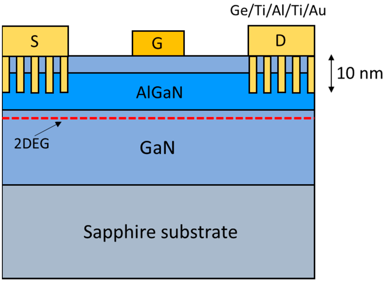
To form ohmic metals, the metal stack of Ge/Ti/Al/Ti/Au was deposited using an e-beam evaporation system (E-gun) with a thickness of 10/20/100/55/105 nm. The source and drain ohmic contacts were then completed by Rapid thermal annealing (RTA) at 850 °C for 30 s in N2 ambient. Finally, Ni/Au was deposited for gate metal with a thickness of 30/80 nm. The gate length (LG), gate-to-drain distance (LGD), and gate-to-source distance (LGS) of the HEMTs were 1.5 µm, 2 µm, and 2.5 µm, respectively. The schematic cross-section of AlGaN/GaN HEMTs with nanohole etching ohmic contacts is depicted in Figure 2.

3. Results and Discussion

3.1. Sub-10 nm Nanohole Patterns

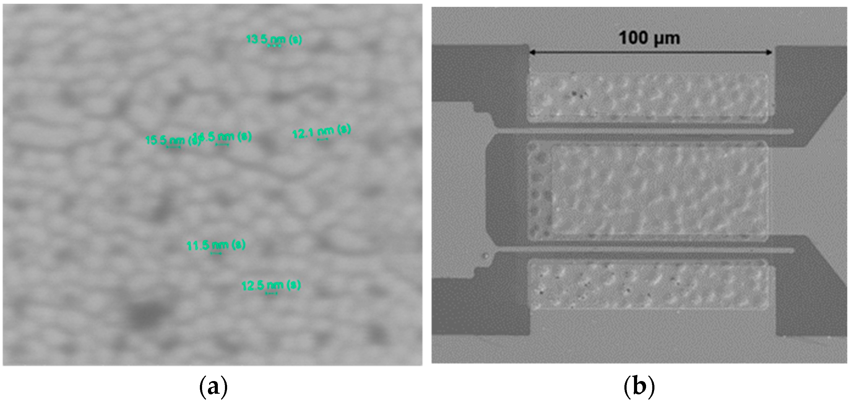
Figure 3a demonstrates the scanning electron microscope (SEM) image of nanohole patterns on the surface of AlGaN using a dwell time of 35 µs after performing e-beam lithography and development at a low temperature of −10 °C for 5 s. It can be seen that the size of the nanoholes ranged from 11.5 to 15.5 nm. It indicated that the sub-10 nm nanohole patterns can be generated successfully on the AlGaN surface by selecting appropriate dwell times and developing rapidly in a low-temperature environment.
Due to the substantial lattice mismatch and differential thermal expansion coefficients between the sapphire substrate and GaN, an elevated defect density is typically induced at the interface of the GaN epitaxial layer, estimated between 1012 and 1013 eV−1cm−2 [31,32,33]. Assuming the interface trap density represents the number of traps per square centimeter, and considering only the planar dimensions, the average area A occupied by each trap is the reciprocal of the trap density, yielding A = 10−12 cm2 for a trap density of 1012 cm−2. Further, if we assume that the area occupied by each trap is equated to a square, the distance between each trap, defined as the side length of the square, can be derived from the square root of the area A. Let s denote the side length, with s = A   = 106 cm, indicating that the average distance between each trap is approximately 0.1 μm. This spacing is critical as it influences the sparsity or density of the interface traps, which in turn significantly impacts the electrical performance of semiconductor devices. Conversely, when the density of interface traps reaches 1013 cm−2, the average distance between individual traps diminishes to about 0.0316 μm, or equivalently 31.6 nm. This reduction in distance indicates a higher density of traps, potentially leading to different electronic properties.
Therefore, we adjusted the dwell times of the electron beam exposure to a range of 5 to 30 μs and combined this with low-temperature short-interval development technology to fabricate etching holes smaller than 31.6 nm. These nanoscale etching holes formed in the ohmic regions on the AlGaN surface, due to their sub-10 nm dimensions being smaller than the average distance between interface traps, thereby enhancing the efficiency of electron tunneling to the metal electrodes, further reducing contact resistance and improving the electrical properties of the devices. In subsequent sections, we will explore the effects of different dwell times on improving sample contact resistance using the TLM method.

3.2. Contact Resistance Evaluation with TLM Measurement

The contact resistance measurement was determined using TLM patterns with spacings ( d ) of 12, 14, 18, and 26 µm, and the width ( W ) was 100 µm. Measurements of total resistance ( R T ) across each contact pair were measured to construct the TLM graph [34] using a four-point probe arrangement, as shown in Figure 4. The measured R T can be expressed by Equation (1) as follows:
R T = ρ s d W + 2 R c ρ s d W + 2 ρ s L T W = ρ s W d + 2 L T
L T 2 = ρ c ρ s
where ρ s is the sheet resistance, L T is the transfer length, and Rc and ρ c are contact resistance and specific contact resistance, respectively. From the graph, the parameter 2Rc can be obtained from the intercept of the y-axis by extrapolating back to d = 0. The comparison of the Rc and ρ c extracted from the TLM data between the conventional structure and patterned etching structures on different dwell times is listed in Table 1.
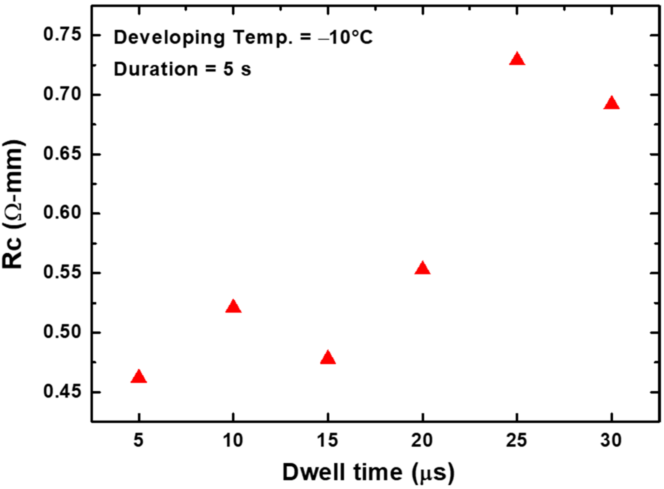
From measurement results listed in Table 1, the sample using a dwell time of 5 µs exhibited the lowest contact resistance of 0.47 Ω-mm and a specific contact resistance of 1.36 × 10⁻⁵ Ω-cm2, which was significantly reduced compared to the sample without etching holes (1.82 Ω-mm and 5.86 × 10⁻⁴ Ω-cm2). Furthermore, it can be seen that the contact resistance was reduced when the dwell times were modulated from 30 to 5 µs. These measurement outcomes demonstrate the efficacy of implementing sub-10 nm nanohole etching within the ohmic regions, which significantly contributes to lowering the contact resistance. Figure 5 illustrates the contact resistance for all the samples using dwell times of 5, 10, 15, 20, 25, and 30 µs. It can be found that when the nanohole pattern was fabricated using dwell times of 25 and 30 µs, the contact resistance was obtained at 0.72 and 0.69 Ω-mm, respectively, which decreased by 60% compared to the conventional structure. To form nanohole patterns with smaller sizes to improve contact resistance further, the dwell times were reduced to under 20 µs. The results showed that when the dwell times were reduced to 10 from 20 µs, the contact resistance could be further improved to 0.49–0.54 Ω-mm, demonstrating an improvement of about 71%. The best performance in contact resistance was found to be 0.47 Ω-mm from the sample using a dwell time of 5 µs as described above. The contact resistance and specific contact resistance of samples using 5 µs dwell times improved by 74% and 97%, respectively, compared to the conventional structure without patterned ohmic contacts.
The observed improvement in contact resistance can be attributed to the significant increase in the sidewall area between the ohmic metal and AlGaN. Facilitated by the nanoscale etching holes, an enormous amount of Ti can chemically react with the AlGaN surface during the thermal annealing of the ohmic metal, forming an increased quantity of TiN and N vacancies [22]. This lowers the barrier height between the ohmic metal and semiconductor, enhancing the electron transport capability and tunneling current, thereby reducing contact resistance. Furthermore, we consider the threading dislocations that occur during the growth of GaN layers on sapphire substrates. These dislocations tend to extend to the surface during the epitaxial growth, thus, when metal-semiconductor contacts are formed, a high density of interface defects is created [26,27]. Such positively charged defect states can capture electrons during their transport, significantly reducing current flow and adversely affecting the contact resistance of the device. Therefore, by fabricating sub-10 nm nanoscale etching holes in the ohmic region and designing a pattern with a density of nanoholes greater than that of the interface defects, we aim to mitigate the negative impact of interface defect density on electron transport and ohmic contact resistance. In this experiment, we leveraged the findings from previous research [28], which demonstrated the formation of a single spot in the photoresist of ZEP520A within a mere 5 µs development duration time. By developing the resist in a low-temperature environment at −10 °C and combining this with dwell times ranging from 5 to 30 µs, we successfully fabricated sub-10 nm nanohole patterns in the AlGaN ohmic region and significantly improved the contact resistance between ohmic metal and AlGaN.

3.3. Effect of Etching Holes on Different Substrate Materials

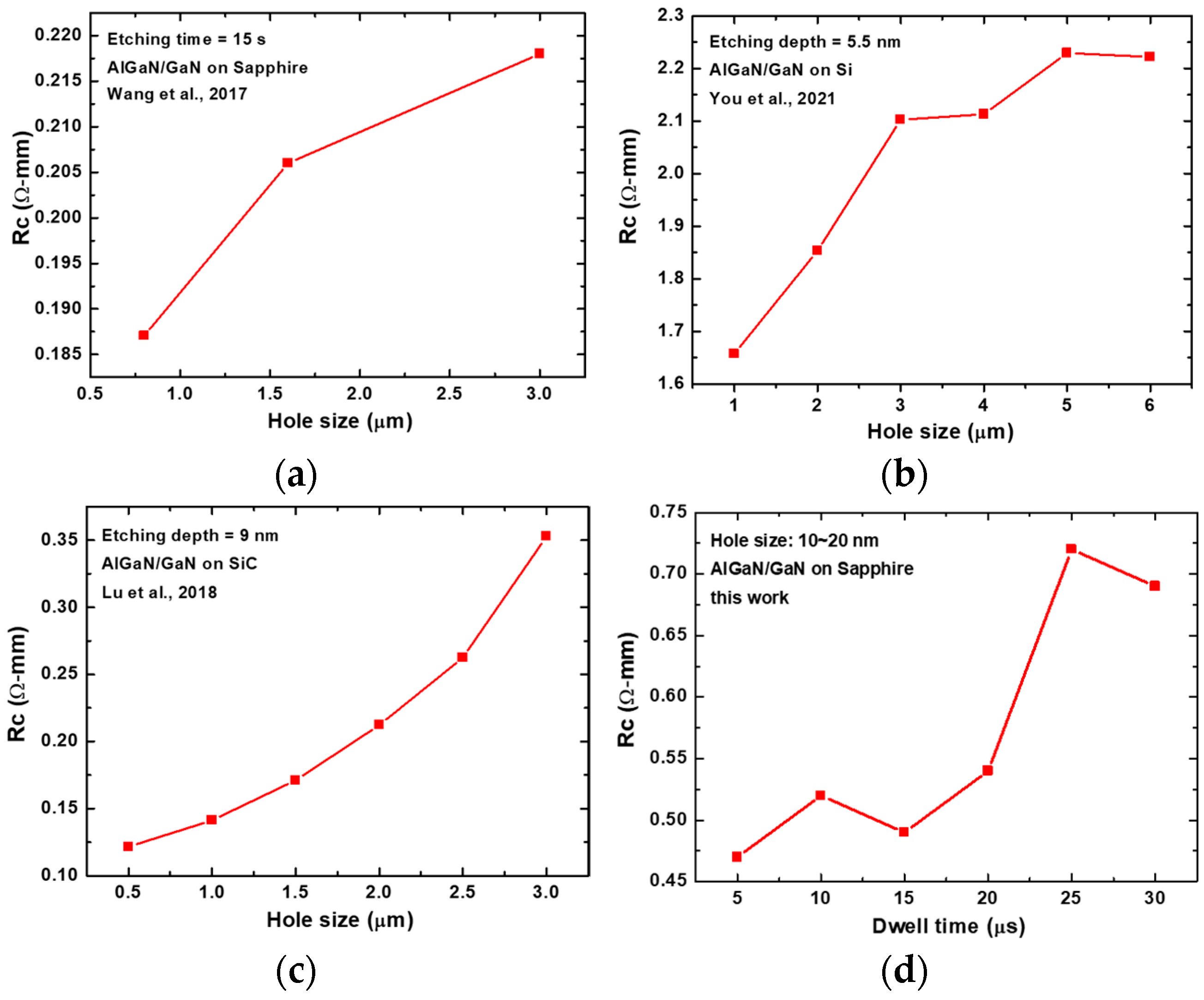
We further investigated the impact of different etch hole sizes on the reduction of Rc in samples when using different substrate materials (Si, Sapphire, SiC). Figure 6a displays the Rc of AlGaN/GaN devices with varying etch hole sizes (0.8, 1.6, and 3.0 μm) grown on sapphire substrates [22]. The conventional structure had an Rc of 0.46 Ω-mm. It was observed that the Rc was 0.218 Ω-mm for etch hole sizes of 3.0 μm, and when the etch hole size was further reduced to 0.8 μm, the Rc was 0.187 Ω-mm. Thus, reducing the hole size from 3.0 μm to 0.8 μm led to an additional 14% decrease in the Rc, effectively reducing the ohmic contact value by 56% compared to the conventional structure. Figure 6b illustrates the Rc of AlGaN/GaN devices grown on Si substrates [24] with various etch hole sizes (1, 2, 3, 4, 5, and 6 μm). The traditional structure had an Rc of 2.66 Ω-mm. It can be seen that the Rc was 2.10 Ω-mm for etch pit sizes of 3 μm. When reduced further to 1 μm, the Rc was 1.66 Ω-mm, indicating a 21% further reduction in the Rc. Compared to the traditional structure, this effectively reduced the ohmic contact value by about 38%. Additionally, only minor changes in contact resistance were observed when the etch hole sizes were 4, 5, and 6 μm. Significant reductions in contact resistance occurred only when the etch hole sizes were below 3 μm.
Figure 6c shows the Rc of AlGaN/GaN devices grown on SiC substrates [35] with etch hole sizes 0.5, 1, 2, and 3 μm. The conventional structure had an Rc of 0.4 Ω-mm. Notably, the Rc was 0.35 Ω-mm for etch holes of 3 μm and decreased to 0.14 Ω-mm when reduced to 1 μm, indicating a substantial 60% reduction. This was an effective 65% decrease in the ohmic contact value compared to the traditional structure. It can be seen that AlGaN/GaN devices with etched ohmic contacts grown on SiC substrates demonstrated a greater reduction in ohmic contact resistance when hole sizes were reduced, compared to those grown on Si and Sapphire substrates. Therefore, we consider that the reduction in etch hole size and the increase in sidewall area are not the only factors in reducing device ohmic contact. The interface defect density produced when growing GaN epitaxial layers on different substrates also affects the effectiveness of introducing etch holes in reducing contact resistance.
From the discussion in Section 3.1, it can be deduced that assuming a GaN epitaxial layer grown on Sapphire has an interface trap density of 1013 cm2, the average distance between defects is approximately 31.6 nm. Generally, GaN layers grown on SiC, due to better lattice matching, have lower interface defect densities compared to Si and Sapphire [36,37]. Thus, micrometer-level etch holes can significantly enhance the electrical resistance properties of HEMT-on-SiC devices. However, for HEMT-on-Si or HEMT-on-Sapphire devices, further reduction in etch pit sizes to the nanometer scale is necessary to mitigate the impact of higher interface defect densities on electron transport capabilities, maximizing the benefits of introducing etched ohmic contacts in improving the electrical performance of HEMT devices.
Figure 6d presents the Rc of AlGaN/GaN devices grown on Sapphire substrates with proposed sub-10 nm etch holes. This study investigates the effects of different electron beam dwell times on improving device contact resistance. The conventional structure had an Rc of 1.82 Ω-mm. It was observed that when the dwell time was 30 and 25 μs, the Rc ranged between 0.69 and 0.72 Ω-mm. When the dwell time was reduced to 5 μs, the Rc was 0.47 Ω-mm, indicating a further reduction of approximately 32%. Compared to the traditional structure, this represents a significant reduction of about 74% in ohmic contact value. The results suggest that utilizing sub-10 nm nano-etched holes in the ohmic regions can further improve the resistance characteristics of HEMT-on-Sapphire devices.

3.4. DC Characteristics of AlGaN/GaN HEMTs Utilizing Sub-10 nm Nanohole Etching

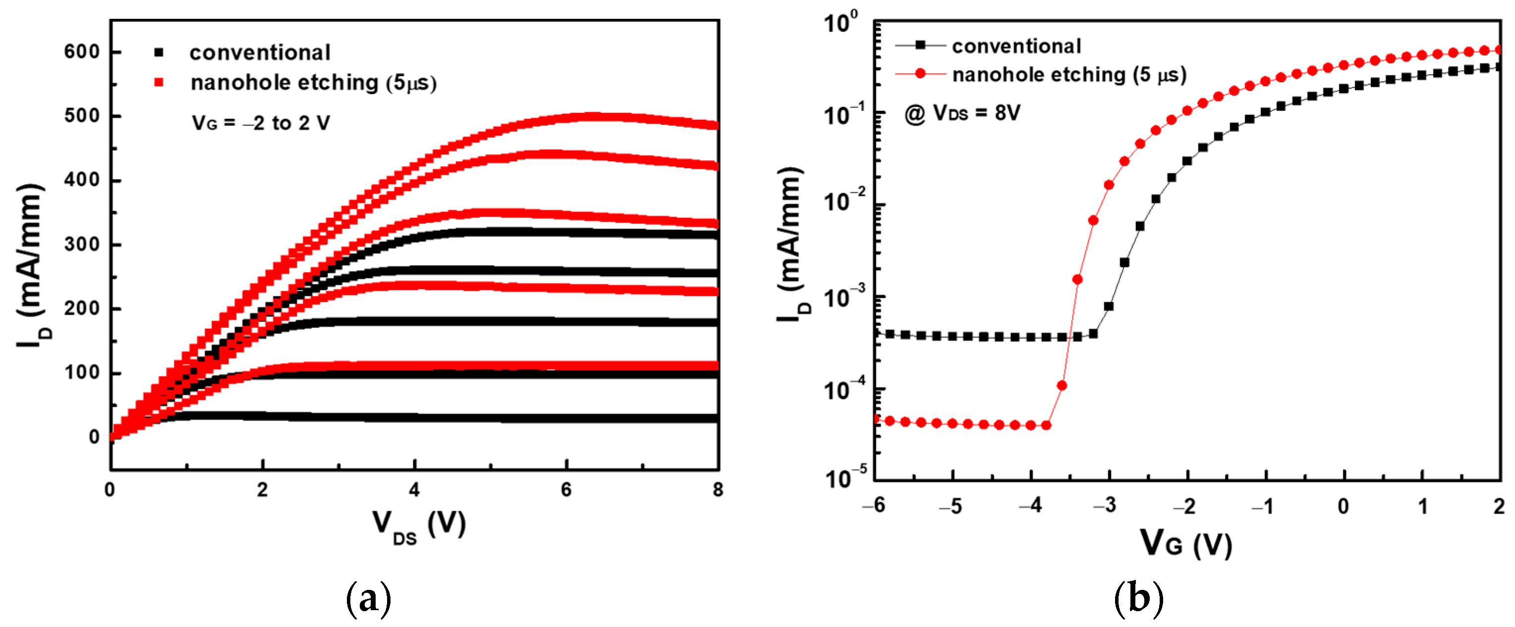
Due to the superior improvement in contact resistance, the sample with a dwell time of 5 µs was adopted to fabricate the HEMT device to optimize the performance. The electrical characteristics for AlGaN/GaN HEMTs fabricated in this work were measured using the Keysight B1500A semiconductor parameter analyzer, sourced from Keysight Technologies, Inc., Santa Rosa, CA, USA. As shown in Figure 7, the IDS-VDS Characteristics of the optimal nanohole etching condition (5 µs dwell time) and the conventional device were demonstrated together for comparison. The maximum drain current density (ID,max) was 496 mA/mm for the patterned etching and 319 mA/mm for the conventional structure, respectively. An enhancement in the drain current density by 55% was observed, which can be attributed to the reduction in the device’s contact resistance. Furthermore, the on-resistance (Ron) of the device was reduced from 1.03 Ω-mm to 0.90 Ω-mm. These results show that introducing etching patterns in the ohmic region can help enhance the fringing effect and augment the side area interaction between the metal and AlGaN [19,22]. This modification is beneficial in reducing the contact resistance, contributing to a higher drain current density and a lower on-resistance of AlGaN/GaN HEMTs.
Figure 7b shows the IDS(log)-VGS characteristics of devices utilizing nanohole etching and conventional structures. It was observed that the leakage current of the device designed with nanoscale contacts decreased by nearly an order of magnitude. However, since an oxide or insulating layer had not yet been applied at the gate region, the leakage current remained excessively high. Thus, future efforts should focus on developing MOS or MIS-HEMT devices to further mitigate the leakage current issue. Figure 8a shows the ID-VGS characteristics of the devices at VDS = 6 V. The threshold voltage exhibited a slightly negative shift and was obtained at −3.54 V for the nanohole etching device. It was found that compared with the conventional structure, the transduction characteristics (gm) of the device greatly improved, from a gm of 80 mS/mm to 135 mS/mm with an increase of 68%, as shown in Figure 8b. This indicates that devices with sub-10 nm nanohole etching have better gate voltage control of the drain current. As high-frequency applications continue to proliferate, optimizing the gm is crucial for enhancing the operating frequencies of HEMT devices. The RF performance enhancement of HEMTs, facilitated by patterned etching of ohmic contacts, has been experimentally validated in previous studies [25,32]. It demonstrates that a higher cut-off frequency (fT) and maximum oscillation frequency (fmax) [25], along with an enhanced power-added efficiency (PAE) [35], can be achieved by patterned etching in the ohmic region.
To maximize the effectiveness of patterned etching ohmic contact for reducing contact resistance and thus enhancing the performance and stability of HEMT devices, it is crucial to identify the optimal etching pattern morphology and process parameters. To date, the exploration of etching patterns to minimize ohmic contact resistance has pursued several directions, including the analysis of various pattern morphologies and arrangements [19,23,24,25], pattern dimensions [22,24,25,32], and etching depths [22,23,24]. Among the diverse etching pattern morphologies paired with different arrangements, commonly utilized ones are symmetrically arranged holes [19,22,23,24,32,34], closely packed holes [38], and lines in the direction of current flow [19,25]. Additionally, some groups have crafted grid-like patterns composed of horizontal and vertical lines [23] and patterns where the holes gradually increase in size from small to large [24], in which You et al. investigated the effects of various hole array arrangements on ohmic contact, confirming that devices with gradually increasing hole patterns of 1/3/5 μm demonstrated lower contact resistance compared to those with uniformly sized patterns. This reduction in contact resistance may be related to the shorter electron transport lengths (LT) facilitated by the increasing hole size, enabling current to reach electrodes via the shortest path [24].
Regarding the selection of pattern dimensions, patterned etching ohmic contact structures are predominantly in the micrometer scale, with hole diameters or side lengths mostly falling between 0.5 and 1.5 μm, while the widths of line patterns range from 1 to 5 μm. The study in [22], examining the impact of three different hole sizes (0.8, 1.6, 3 μm) on contact resistance, attributed the lowest contact resistance value of 0.46 Ω-mm for 0.8 μm holes to the increased sidewall area created by patterned etching on the AlGaN surface. This increased sidewall area facilitates more extensive chemical reactions between the ohmic metal and AlGaN during the annealing process, resulting in more TiN and N vacancies, thus enhancing the tunneling current and reducing contact resistance. To achieve a high RF performance in AlGaN/GaN HEMT-on SiC, Lu et al. analyzed the effect of six different hole diameters (0.5, 1.0, 1.5, 2.0, 2.5, and 3.0 μm) on contact resistance, demonstrating a significant reduction in contact resistance with decreasing dimensions. The smallest 0.5 μm holes achieved the lowest contact resistance of 0.12 Ω-mm, marking a 70% improvement and effectively enhancing RF efficiency and power characteristics [35]. Table 2 lists the pattern and contact resistance of previous studies using a patterned ohmic contact (POC) structure in AlGaN/GaN heterostructures. Different from previous studies that focused on micro-patterned ohmic structures, in this work, we fabricated symmetrically arranged etching nanohole structures on the sub-10 nm scale and improved the contact resistance from 1.82 to 0.47 Ω-mm, achieving a 74% improvement. Further optimization of the etching depth and hole arrangement in nanohole etching patterns is still required. To further reduce contact resistance by ohmic etching patterns, designing optimal etching pattern morphologies is essential and can be achieved with etching patterns that can increase the contact side area between the metal and AlGaN, arrangements that optimize the current path to reach the electrodes, and optimal etching depths to enhance fringing effects.
Furthermore, selecting optimized process parameters is also required to form effective ohmic contacts between the metal and the semiconductor. Generally, annealing temperatures range between 800 and 900 °C to facilitate good diffusion and chemical reactions between the metal and AlGaN/GaN heterostructure [38]. Nonetheless, the morphology of both surfaces and sidewalls often deteriorates during the annealing process, and the annealing temperature critically affects the size and density distribution of the TiN phase grains. Therefore, optimizing the annealing temperature for uneven AlGaN structures is indispensable. Most devices with patterned etching AlGaN ohmic contacts use a Ti/Al/Ni/Au metal stack, with annealing temperatures set between 790 and 850 °C. In [23,38], the impact of annealing temperature on patterned etching ohmic contacts was investigated by using different annealing temperatures after ohmic metallization. The results showed that the optimized annealing temperature for AlGaN/GaN heterostructures with etched hole arrays was 40 °C lower than that for conventional structures [38]. Additionally, to address the issue of current collapse, some groups have used an Au-free Ti/Al/Ti for ohmic contacts with a low annealing temperature of 550 °C, creating AlGaN/GaN HEMTs with a low thermal budget and reduced contact resistance [33,34]. In this work, we used an 850 °C annealing temperature for the ohmic metal for 30 s. Given that the annealing temperature can significantly impact contact resistance increased from 0.2 to around 0.35 Ω-mm when the annealing temperature increased from 800 to 820 °C, further optimization of the annealing temperature and annealing time for nanoscale patterned ohmic contacts is necessary to allow the ohmic metal to effectively infiltrate the etched holes in AlGaN and achieve better TiN phase formation. For the use of a patterned etching ohmic contact to reduce contact resistance, further investigations on the optimization of etching pattern morphology and process parameters are indispensable to enhancing the performance and stability of devices and unlocking the potential of AlGaN/GaN HEMTs in high-power and high-frequency applications. Table 3 lists the optimal contact resistance of previous works using patterned ohmic contact with different patterns and dimensions.

4. Conclusions

In conclusion, this study demonstrates a significant improvement in the contact resistance of AlGaN/GaN HEMTs through the introduction of nanoscale hole arrays in the ohmic area. Comparative analyses between the conventional structure and the nanohole etching structure were conducted, revealing notable enhancements in the DC characteristics of the HEMTs. The implementation of sub-10 nm nanoholes, patterned using electron beam lithography and low-temperature short-time development, was instrumental in this advancement. Our investigation into various dwell times for e-beam exposure, ranging from 5 to 30 μs, indicated that a dwell time of 5 μs for nanohole formation was optimal. This resulted in a reduction in contact resistance from 1.82 to 0.47 Ω-mm, compared to the conventional structure. The DC characteristics of the HEMTs showed an increase in the maximum drain current from 319 to 496 mA/mm and transconductance from 80 to 135 mS/mm. These findings highlight that devices with sub-10 nm nanohole ohmic contacts not only exhibit a lower contact resistance but also enhance overall device performance, including a lower on-resistance and a higher maximum drain current.

Author Contributions

Conceptualization, C.-H.K.; Investigation, H.-J.L., C.-C.L. and H.-R.P.; Data curation, H.-J.L. and H.-R.P.; Writing—original draft preparation, H.-J.L. and H.-R.P.; Writing—review and editing, H.-J.L.; Supervision, C.-C.L. and C.-H.K. All authors have read and agreed to the published version of the manuscript.

Funding

This research was funded by the Ministry of Science and Technology (MOST), Taiwan, under contract number MOS 111-2221-E-002-170-MY3.

Data Availability Statement

The data presented in this study are available on request from the corresponding author.

Conflicts of Interest

The authors declare no conflicts of interest.

References

  1. Haziq, M.; Falina, S.; Manaf, A.A.; Kawarada, H.; Syamsul, M. Challenges and Opportunities for High-Power and High-Frequency AlGaN/GaN High-Electron-Mobility Transistor (HEMT) Applications: A Review. Micromachines 2022, 13, 2133. [Google Scholar] [CrossRef] [PubMed]
  2. Ambacher, O.; Foutz, B.; Smart, J.; Shealy, J.R.; Weimann, N.G.; Chu, K.; Murphy, M.; Sierakowski, A.J.; Schaff, W.J.; Eastman, L.F.; et al. Two dimensional electron gases induced by spontaneous and piezoelectric polarization in undoped and doped AlGaN/GaN heterostructures. J. Appl. Phys. 2000, 87, 334. [Google Scholar] [CrossRef]
  3. Hsu, C.-W.; Lin, Y.-C.; Lee, M.-W.; Chang, E.-Y. Investigation of the Effect of Different SiNx Thicknesses on the Characteristics of AlGaN/GaN High-Electron-Mobility Transistors in Ka-Band. Electronics 2023, 12, 4336. [Google Scholar] [CrossRef]
  4. Jones, E.A.; Wang, F.; Costinett, D. Review of Commercial GaN Power Devices and GaN-Based Converter Design Challenges. IEEE J. Emerg. Sel. Top. Power Electron. 2016, 4, 707–719. [Google Scholar] [CrossRef]
  5. Nakatani, K.; Yamaguchi, Y.; Komatsuzaki, Y.; Sakata, S. A Ka-Band High Efficiency Doherty Power Amplifier MMIC using GaN-HEMT for 5G Application. In Proceedings of the 2018 IEEE MTT-S International Microwave Workshop Series on 5G Hardware and System Technologies (IMWS-5G), Dublin, Ireland, 30–31 August 2018. [Google Scholar]
  6. Weng, Y.-C.; Lin, Y.-C.; Hsu, H.-T.; Kao, M.-L.; Huang, H.-Y.; Ueda, D.; Ha, M.-T.-H.; Yang, C.-Y.; Maa, J.-S.; Chang, E.-Y.; et al. A Novel GaN:C Millimeter-Wave HEMT with AlGaN Electron-Blocking Layer. Materials 2022, 15, 703. [Google Scholar] [CrossRef] [PubMed]
  7. Saito, W.; Kuraguchi, M.; Takada, Y.; Tsuda, K.; Omura, I.; Ogura, T. High breakdown Voltage undoped AlGaN-GaN power HEMT on sapphire substrate and its demonstration for DC-DC converter application. IEEE Trans. Electron Devices 2004, 51, 1913–1917. [Google Scholar] [CrossRef]
  8. Mohanbabu, M.; Mohankumar, N.; Godwin Raj, D.; Sarkar, P.; Saha, S.K. Efficient III-Nitride MIS-HEMT devices with high-κ gate dielectric for high-power switching boost converter circuits. Superlattices Microstruct. 2017, 103, 270–284. [Google Scholar] [CrossRef]
  9. Zhou, Y.; Mi, M.; Yang, M.; Han, Y.; Wang, P.; Chen, Y.; Liu, J.; Gong, C.; Lu, Y.; Zhang, M.; et al. High performance millimeter-wave InAlN/GaN HEMT for low voltage RF applications via regrown Ohmic contact with contact ledge structure. Appl. Phys. Lett. 2022, 120, 062104. [Google Scholar] [CrossRef]
  10. Yadav, Y.K.; Upadhyay, B.B.; Meer, M.; Ganguly, S.; Saha, D. Reduced Contact Resistance and Improved Transistor Performance by Surface Plasma Treatment on Ohmic Regions in AlGaN/GaN HEMT Heterostructures. Phys. Status Solidi A 2018, 215, 1700656. [Google Scholar] [CrossRef]
  11. Chung, J.W.; Hoke, W.E.; Chumbes, E.M.; Palacios, T. AlGaN/GaN HEMT with 300-GHz. IEEE Electron Dev. Lett. 2010, 31, 195–197. [Google Scholar] [CrossRef]
  12. Saito, W.; Takada, Y.; Kuraguchi, M.; Tsuda, K.; Omura, I. Recessed-gate structure approach toward normally off high-Voltage AlGaN/GaN HEMT for power electronics applications. IEEE Trans. Electron Devices 2006, 53, 356–362. [Google Scholar] [CrossRef]
  13. Bright, A.N.; Thomas, P.J.; Weyland, M.; Tricker, D.M.; Humphreys, C.J.; Davies, R. Correlation of contact resistance with microstructure for Au/Ni/Al/Ti/AlGaN/GaN ohmic contacts using transmission electron microscopy. J. Appl. Phys. 2001, 89, 3143–3150. [Google Scholar] [CrossRef]
  14. Bardwell, J.A.; Sproule, G.I.; Liu, Y.; Tang, H.; Webb, J.B.; Fraser, J.; Marshall, P. Comparison of two different Ti/Al/Ti/Au ohmic metallization schemes for AlGaN/GaN. J. Vac. Sci. Technol. B 2002, 20, 1444–1447. [Google Scholar] [CrossRef]
  15. Selvanathan, D.; Zhou, L.; Kumar, V.; Adesida, I. Low Resistance Ti/Al/Mo/Au Ohmic Contacts for AlGaN/GaN Heterostructure Field Effect Transistors. Phys. Status Solidi (A) 2002, 194, 583–586. [Google Scholar] [CrossRef]
  16. Yadav, Y.K.; Upadhyay, B.B.; Meer, M.; Bhardwaj, N.; Ganguly, S.; Saha, D. Ti/Au/Al/Ni/Au Low Contact Resistance and Sharp Edge Acuity for Highly Scalable AlGaN/GaN HEMTs. IEEE Electron Device Lett. 2019, 40, 67–70. [Google Scholar] [CrossRef]
  17. Nguyen, C.; Shah, P.; Leong, E.; Derenge, M.; Jones, K. Si implant-assisted Ohmic contacts to GaN. Solid-State Electron. 2010, 54, 1227–1231. [Google Scholar] [CrossRef]
  18. Yue, Y.; Hu, Z.; Guo, J.; Sensale-Rodriguez, B.; Li, G.; Wang, R.; Faria, F.; Fang, T.; Song, B.; Gao, X.; et al. InAlN/AlN/GaN HEMTs with Regrown Ohmic Contacts and fT of 370 GHz. IEEE Electron Dev. Lett. 2012, 33, 988–990. [Google Scholar] [CrossRef]
  19. Takei, Y.; Kamiya, M.; Tsutsui, K.; Saito, W.; Kakushima, K.; Wakabayashi, H.; Kataoka, Y.; Iwai, H. Reduction of contact resistance on AlGaN/GaN HEMT structures introducing uneven AlGaN layers. Phys. Status Solidi A 2015, 212, 1104–1109. [Google Scholar] [CrossRef]
  20. Takei, Y.; Tsutsui, K.; Saito, W.; Kakushima, K.; Wakabayashi, H.; Iwai, H. Dependence of ohmic contact properties on AlGaN layer thickness for AlGaN/GaN high-electron-mobility transistors. Jpn. J. Appl. Phys. 2016, 55, 040306. [Google Scholar] [CrossRef]
  21. Gudkov, A.G.; Shashurin, V.D.; Vyuginov, V.N.; Tikhomirov, V.G.; Vidyakin, S.I.; Agasieva, S.V.; Gorlacheva, E.N.; Chizhikov, S.V. The Influence of AlGaN Barrier-Layer Thickness on the GaN HEMT Parameters for Space Applications. In Proceedings of the Scientific-Practical Conference “Research and Development—2016”, Moscow, Russia, 14–15 December 2016. [Google Scholar]
  22. Wang, C.; Zhao, M.D.; He, Y.L.; Zheng, X.F.; Wei, X.X.; Mao, W.; Ma, X.H.; Zhang, J.C.; Hao, Y. Optimization of ohmic contact for AlGaNGaN HEMT by introducing patterned etching in ohmic area. Solid-State Electron. 2017, 129, 114–119. [Google Scholar] [CrossRef]
  23. Benakaprasad, B.; Eblabla, A.M.; Li, X.; Crawford, K.G.; Elgaid, K. Optimization of Ohmic Contact for AlGaN/GaN HEMT on Low-Resistivity Silicon. IEEE Trans. Electron Devices 2020, 67, 863–868. [Google Scholar] [CrossRef]
  24. You, X.R.; Chen, C.W.; Tzou, J.; Hsin, Y.M. Study of Au-Based and Au-Free Ohmic Contacts in AlGaN/GaN HEMTs by Recessed Patterns. ECS J. Solid State Sci. Technol. 2021, 10, 075006. [Google Scholar] [CrossRef]
  25. Lee, M.-W.; Chuang, C.-W.; Gamiz, F.; Chang, E.-Y.; Lin, Y.-C. Improvement of AlGaN/GaN High-Electron-Mobility Transistor Radio Frequency Performance Using Ohmic Etching Patterns for Ka-Band Applications. Micromachines 2024, 15, 81. [Google Scholar] [CrossRef] [PubMed]
  26. Yu, C.H.; Luo, Q.Z.; Luo, X.D.; Liu, P.S. Donor-Like Surface Traps on Two-Dimensional Electron Gas and Current Collapse of AlGaN/GaN HEMTs. Sci. World J. 2013, 2013, 931980. [Google Scholar] [CrossRef] [PubMed]
  27. Marino, F.A.; Ferry, D.K. Effects of threading dislocations on AlGaN/GaN high-electron mobility transistors. IEEE Trans. Electron Devices 2010, 57, 353–360. [Google Scholar] [CrossRef]
  28. Chang, L.C.; Nien, C.; Ye, J.H.; Chung, C.H.; Su, V.C.; Wu, C.H.; Kuan, C.H. A comprehensive model for sub-10 nm electron beam patterning through the short-time and cold development. Nanotechnology 2017, 28, 425301. [Google Scholar] [CrossRef] [PubMed]
  29. Yang, J.; Liu, K.; Chen, X.; Shen, D. Recent advances in optoelectronic and microelectronic devices based on ultrawide-bandgap semiconductors. Prog. Quantum Electron. 2022, 83, 100397. [Google Scholar] [CrossRef]
  30. Bruni, F.J. Crystal growth of sapphire for substrates for high-brightness, light emitting diodes. Cryst. Res. Technol. 2015, 50, 133–142. [Google Scholar] [CrossRef]
  31. Gao, J.; Hao, M.; Li, W.; Xu, Z.; Mandal, S.; Nemanich, R.; Chowdhury, S. Al2O3 Insertion Layer for Improved PEALD SiO2/(Al)GaN Interfaces. Phys. Status Solidi A 2018, 215, 1700498. [Google Scholar] [CrossRef]
  32. Liao, W.-C.; Chiang, C.-T.; Chyi, J.-I.; Hsin, Y.-M. Reduced Interface States of Atomic-Layer-Deposited Al2O3/AlGaN/GaN Heterostructure Containing In Situ Grown AlN/GaN Cap Layer and Subjected to Thermal Oxidation. J. Electrochem. Soc. 2015, 162, E160–E165. [Google Scholar] [CrossRef]
  33. Kordoš, P.; Stoklas, R.; Gregušová, D.; Novák, J. Characterization of AlGaN/GaN metal-oxide-semiconductor field-effect transistors by frequency dependent conductance analysis. Appl. Phys. Lett. 2009, 94, 2235. [Google Scholar] [CrossRef]
  34. Duffy, S.J.; Benbakhti, B.; Mattalah, M.; Zhang, W.; Bouchilaoun, M.; Boucherta, M.; Kalna, K.; Bourzgui, N.; Maher, H.; Soltani, A. Low Source/Drain Contact Resistance for AlGaN/GaN HEMTs with High Al Concentration and Si-HP [111] Substrate. ECS J. Solid State Sci. Technol. 2017, 6, S3040–S3043. [Google Scholar] [CrossRef]
  35. Lu, Y.; Ma, X.; Yang, L.; Hou, B.; Mi, M.; Zhang, M.; Zheng, J.; Zhang, H.; Hao, Y. High RF Performance AlGaN/GaN HEMT Fabricated by Recess-Arrayed Ohmic Contact Technology. IEEE Electron Device Lett. 2018, 39, 811–814. [Google Scholar] [CrossRef]
  36. Pharkphoumy, S.; Janardhanam, V.; Jang, T.-H.; Shim, K.-H.; Choi, C.-J. Correlation of Crystal Defects with Device Performance of AlGaN/GaN High-Electron-Mobility Transistors Fabricated on Silicon and Sapphire Substrates. Electronics 2023, 12, 1049. [Google Scholar] [CrossRef]
  37. Pandey, a.; Singh, V.K.; Dalal, S.; Bag, R.K.; Narang, K.; Kaur, D.; Raman, R.; Tyagi, R. Effect of two step GaN buffer on the structural and electrical characteristics in AlGaN/GaN heterostructure. Vacuum 2020, 178, 109442. [Google Scholar] [CrossRef]
  38. Han, K. Employing hole-array recess of barrier layer of AlGaN/GaN Heterostructures to reduce annealing Temperature of Ohmic contact. Semicond. Sci. Technol. 2017, 32, 105010. [Google Scholar] [CrossRef]
  39. Wang, Y.; Huang, S.; Wang, X.; Kang, X.; Zhao, R.; Zhang, Y.; Zhang, S.; Fan, J.; Yin, H.; Liu, C.; et al. Effects of Fluorine Plasma Treatment on Au-Free Ohmic Contacts to Ultrathin-Barrier AlGaN/GaN Heterostructure. IEEE Trans. Electron Devices 2019, 66, 2932–2936. [Google Scholar] [CrossRef]
  40. You, X.-R.; Chen, C.-W.; Tzou, J.; Hsin, Y.-M. Low-thermal-budget Au-free ohmic contact to an ultrathin barrier AlGaN/GaN heterostructure utilizing a micro-patterned ohmic recess. J. Semicond. 2021, 42, 092801. [Google Scholar]
Figure 1. Schematic diagram of nanohole etching patterns in ohmic regions on the surface of the AlGaN barrier layer.
Electronics 13 02490 g001
Figure 2. Schematic diagram of the AlGaN/GaN HEMT utilizing a nanohole etching ohmic contacts.
Electronics 13 02490 g002
Figure 3. (a) SEM image of nanohole patterns on the surface of AlGaN using dwell time of 35 µs. (b) Top-view SEM image of the device using patterned etching ohmic contacts.
Electronics 13 02490 g003
Figure 4. Measurement of total resistance for samples with patterned etching (5 µs) compared to a conventional sample using the TLM method.
Electronics 13 02490 g004
Figure 5. Extracted contact resistance for all the samples using dwell times of 5, 10, 15, 20, 25, and 30 µs.
Electronics 13 02490 g005
Figure 6. The Rc of AlGaN/GaN samples grown on (a) sapphire (Wang et al., 2017 [22]), (b) Si (You et al., 2021 [24]), and (c) SiC (Lu et al., 2018 [35]) using different hole sizes, and (d) sapphire substrates using different dwell times.
Electronics 13 02490 g006
Figure 7. (a) ID-VDs and (b) IDS(log)-VGS characteristics of devices utilizing nanohole etching and conventional structure.
Electronics 13 02490 g007
Figure 8. (a) ID-VGs characteristics and (b) transconductance of devices utilizing nanohole etching and conventional structure.
Electronics 13 02490 g008
Table 1. Contact resistance and specific contact resistance of samples using different dwell times.
Dwell Time (µs)Rc (Ω-mm)ρc (Ω-cm2)
Conventional1.825.86 × 10−4
50.471.36 × 10−5
100.521.65 × 10−5
150.491.47 × 10−5
200.541.66 × 10−5
250.721.89 × 10−5
300.691.81 × 10−5
Table 2. Comparison of DC characteristics of AlGaN/GaN HEMTs.
HEMTID,max (mA/mm)Ron (Ω-mm)gm (mS/mm)
conventional3191.0380
nanohole etching4960.90135
Table 3. The pattern and contact resistance of previous works using patterned ohmic contact (POC).
PatternSize
(μm)
Conventional
Rc
(Ω-mm)
POC Structure
Rc
(Ω-mm)
Ref.Year
Horizontal line5-5.86[19]2015
Close hole1-0.20[38]2017
Square hole0.80.460.18[22]2017
Square hole0.50.400.12[35]2018
Grid line20.3680.278[23]2020
Graded hole1/3/5-0.89[24]2021
Square hole1.51.570.56[39,40]2021
Horizontal line 10.4290.154[25]2024
Square hole<0.02 × 0.021.820.47this work
Disclaimer/Publisher’s Note: The statements, opinions and data contained in all publications are solely those of the individual author(s) and contributor(s) and not of MDPI and/or the editor(s). MDPI and/or the editor(s) disclaim responsibility for any injury to people or property resulting from any ideas, methods, instructions or products referred to in the content.