Abstract
Traditionally, studies have primarily focused on single event effects in aerospace electronics. However, current research has confirmed that atmospheric neutrons can also induce single event effects in China’s advanced technology relay protection devices. Spallation neutron irradiation tests on a Loongson 2K1000 system-on-chip based relay protection device have revealed soft errors, including abnormal sampling, refusal of operation and interlock in the relay protection device. Given the absence of standardized evaluation methods for single event effects on relay protection devices, the following research emphasizes the use of Monte Carlo simulation and software fault injection. Various types of single event upsets, such as single bit upsets, dual bit upsets, and even eight bit upsets, were observed in Monte Carlo simulations where atmospheric neutrons hit the chip from different directions (top and bottom). The simulation results indicated that the single event effect sensitivity of the relay protection device was similar whether the neutron hit from the top or the bottom. Through software fault injection, the study also identified soft errors caused by neutron induced single event upsets on the Loongson 2K1000 system, including failure to execute, system halt, time out, and error result. And the soft error number of system halts and error results exceeded that of time outs and failures to execute in all three tested programs. This research represents a preliminary assessment of single event effects on relay protection devices and is expected to provide valuable insights for evaluating the reliability of advanced technology relay protection devices.
1. Introduction
Relay protection devices are crucial components in power systems, serving the important function of swiftly disconnecting faults and maintaining the stability of the grid [1,2,3]. The reliability of these devices has a direct impact on the overall stability of the grid [4,5,6]. Relay protection devices commonly embrace emerging applications and advanced semiconductor technologies [7,8]. However, these advancements also introduce new challenges, such as the susceptibility to single event effects (SEE) induced by atmospheric neutrons.
In the field of aerospace electronic systems, significant attention has traditionally been given to SEE due to the presence of energetic particles. These particles can deposit energy and cause single event upsets (SEU) and other effects [9,10]. However, there is relatively little focus on the impact of SEE on advanced technology relay protection devices. When evaluating factors influencing the reliability of advanced technology relay protection devices, the emphasis has typically been on voltage, temperature, electromagnetic interference, and others rather than SEE [11]. In [12], the overvoltage and undervoltage effect on relay protection devices was discussed. In [13], the impact of a static var compensator on a distance protection relay was evaluated. In [14], a test device simulating live verification relay protection as designed. In [15], an intelligent relay protection system was developed, and the system can automatically select a relay protection set point basing initial data on weather conditions, time of year, soil resistance, current, voltage, etc. In [16], the failure causes of relay protection switching power supply were explored. In [17], the author provided a reliable quantitative basis for relay protection systems’ operating maintenance by the aid of a semi-supervised Mahalanobis distance machine learning algorithm. And in [18], authors subdivided the influence factors of incorrect actions on relay protection devices of the State Grid Corporation of China from 2006 to 2017; they considered the causes of incorrect actions mainly from defects in relay protection devices, secondary circuits or communication systems. In [19,20], the outstanding engineers, K. Zimmerman and D. Haas from Schweitzer Engineering Laboratories, appealed to the manufactures and end users to continuously monitor and work toward improving overall system design to mitigate single event effects. All these facts indicate that the field of relay protection device currently lacks consideration of single event effects, as it primarily concentrates on conventional factors. Especially with the increase use of advanced technology semiconductor devices in the field of relay protection, the continued neglect of single event effects on relay protection devices may lead to unpredictable consequences. Therefore, it is crucial to urgently conduct research on single event effects of advanced technology relay protection devices in the present and near future.
Relay protection devices typically operate in terrestrial environments where they are exposed to atmospheric neutrons. These neutrons possess a broad energy spectrum, ranging from meV to GeV [21]. When these neutrons interact with atomic nuclei in semiconductors, they can induce SEE. For example, high-energy neutrons may react with silicon and produce secondary high-energy heavy ions, while thermal neutrons can interact with boron contamination and generate energetic secondary particles. These energetic secondary ions/particles can deposit energy in the semiconductor and result in SEE [22]. It can be speculated that as more advanced semiconductor devices are utilized in relay protection devices, the risk of SEE also increases. Therefore, it becomes crucial to pay more attention to this issue. Notably, there have been recorded incidents of SEE in Chinese relay protection devices in 2018 and 2020 [23,24]. These incidents highlight the importance of assessing the impact of SEE on relay protection devices in China. As the largest supplier of complete electric power equipment in China and an active participant in the global power industry, the NARI Group Corporation (NARI) has an obligation and responsibility to acquire knowledge of atmospheric neutron SEE on advanced technology relay protection devices in China [25]. As a result, our current research is dedicated to addressing the influence of SEE on Chinese relay protection devices.
The spallation neutron source is an excellent candidate for conducting atmospheric neutron induced SEE evaluation [26]. With the operation of the China Spallation Neutron Source (CSNS), it has become feasible to study atmospheric neutron SEE in China [27,28]. Due to factors such as uncertainty in irradiation tests, irradiation hours, and cost, the current study primarily focuses on using spallation neutron irradiation to confirm whether SEE can affect the target relay protection device, specifically the Loongson 2K1000 system-on-chip based development kit. Once this confirmation is established, greater emphasis and effort are placed on software fault injection. Compared to irradiation testing, software fault injection allows for more detailed insights that may be challenging to extract solely through irradiation [29]. Additionally, the fault injection technique relies on the results of Monte Carlo simulations, which utilize models constructed from the tested chip. Through these efforts, detailed soft errors induced by atmospheric neutron SEE on the advanced technology relay protection devices can be examined and evaluated.
The structure of the paper is as follows: Section 2 provides an introduction to relay protection architecture. Section 3 introduces SEE assessment framework on relay protection device. Section 4 briefs the spallation neutron source irradiation, and Section 5 presents the Monte Carlo simulation. Then, Section 6 details the fault injection based on Monte Carlo outcomes, and Section 7 analyzes the results. Finally, we draw conclusions based on our findings in Section 8.
2. Relay Protection Architecture
A relay protection device generally consists of various modules that perform different functions and are interconnected through buses or interfaces. Some common modules found in a relay protection device include the input module, protection module, management module, power supply module, etc.
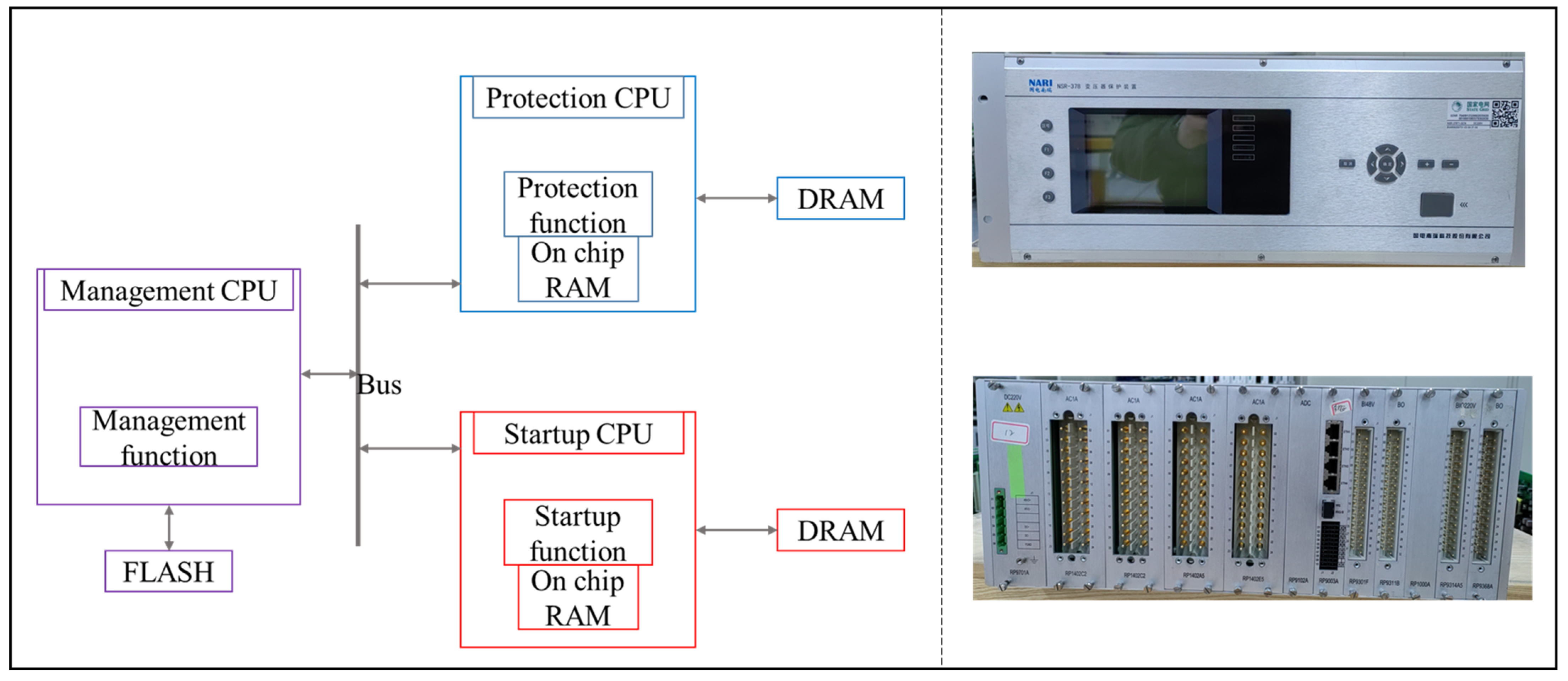
These modules primarily consist of three types of CPUs (Central Processing Units): protection CPU, startup CPU, and management CPU. The protection and startup CPUs are responsible for signal sampling, protection processing, and trip control. The management CPU handles recording, human–machine interface communication, and other related tasks. The architecture of the key CPUs can be observed in the left section of Figure 1.
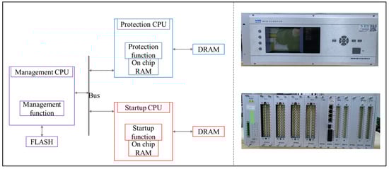
Figure 1.
Architecture of the key CPUs in relay protection devices and the equipment photo of the Loongson 2K1000 system-on-chip based relay protection equipment; the left part is the architecture of the key CPUs, and the right part shows the photo of the front side and the back side of the terminal connector in the top and bottom.
The Loongson 2K1000 system-on-chip development kit plays a crucial role in the relay protection system of the Chinese power grid, particularly within the integrated dual CPUs. The kit features the dual-GS264 processor, which operates at a maximum frequency of 1 GHz. Each core of the processor is equipped with independent two level instruction and data caches and on-chip random access memory (RAM). Furthermore, the processor incorporates a diverse array of high-speed interfaces [30]. In the Loongson 2K1000 system-on-chip development kit, one processor serves as the management CPU, while the other is multiplexed to act as the startup CPU during the launch stage. Once launched, it assumes the role of the protection CPU. The right section of Figure 1 shows the front and back sides of the relay protection equipment.
In the context of relay protection architecture, the on-chip RAM (random access memory), DRAM (dynamic random access memory), and Flash serve as essential data storage media. However, these storage media are susceptible to SEE [31,32]. In addition, the registers in the CPUs may also suffer from SEE. The occurrence of SEE in these memories can lead to unexpected outcomes in the power grid, potentially resulting in incalculable losses. Thus, the fault injection and the Monte Carlo simulations were mainly performed on the memory block.
3. SEE Assessment Framework on Relay Protection Devices
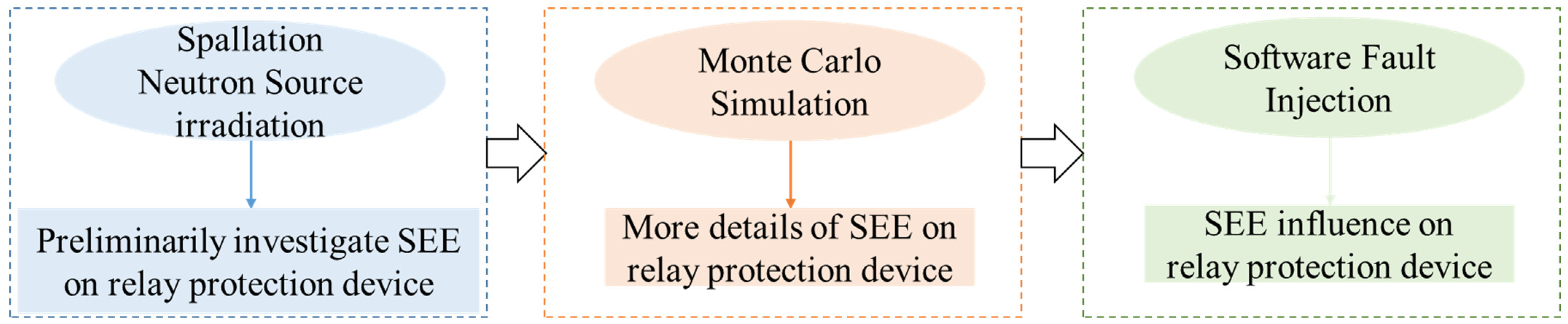
As mentioned above, there can be a lack of outcomes in relay protection SEE assessment. To address this issue, considering the operations of CSNS, we proposed a research framework that combined spallation neutron source irradiation testing, Monte Carlo simulations, and software fault injection to assess SEE influence on relay protection devices. Figure 2 shows the framework of the current study in which the irradiation test checked whether the atmospheric neutron could induce SEE on relay protection. Then, the Monte Carlo simulation provided details about SEE, such as the distribution of multi bit upsets. At the same time, the Monte Carlo simulation also provides the upset information during software fault injection.
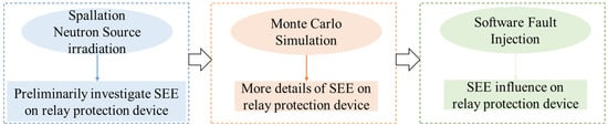
Figure 2.
Framework of SEE assessment on relay protection devices.
4. Spallation Neutron Source Irradiation
In the absence of an established standard for spallation neutron source SEE evaluation in relay protection devices and limited research in this area, it was crucial to investigate whether any SEE can be detected during the spallation neutron irradiation process.
The primary objective of the irradiation was to examine the occurrence of SEE in relay protection devices when the device under test (DUT) was exposed to atmospheric neutron irradiation at the CSNS end. In the irradiation test, the DUT was placed at the distance of 17.5 cm from the terminal in the irradiation room. The neutron spectrum was derived from the actual atmospheric fluence with a significant magnification factor. At CSNS, the synchrotron accumulated and accelerated the proton beam to 1.6 GeV. Then, the beam was extracted in a single turn and was delivered to the metal target through the ring-to-target beam transport. The ultra-high-energy protons impinged on the metal target and produced spallation neutrons applied in irradiation tests [33]. During irradiation, the equivalent high-energy neutron fluence was about 3 × 10⁷ neutrons/(cm2⋅s) with an intended continuous exposure time of 10 min. If a soft error was detected during this process, a new round irradiation test was initiated. Ultimately, soft errors, including abnormal sampling, relay protection refusal to operate, and relay protection device interlock, were detected. They are defined as follows:
- ⮚
- Abnormal sampling: the sample value is out of range as expected during irradiation;
- ⮚
- Protection refusal to operate: it fails to perform its intended protective function even when it receives a fault signal;
- ⮚
- Relay protection device interlock: the device is intentionally prevented from tripping or operating in response to a fault signal.
These findings demonstrate that atmospheric neutrons cause SEE in relay protection devices and indeed result in unexpected outcomes. And it emphasizes the urgent need to conduct more detailed research about SEE assessment on relay protection device. This also highlights that our current research is valuable and has practical significance.
5. Monte Carlo Simulation
5.1. Simulation Construction
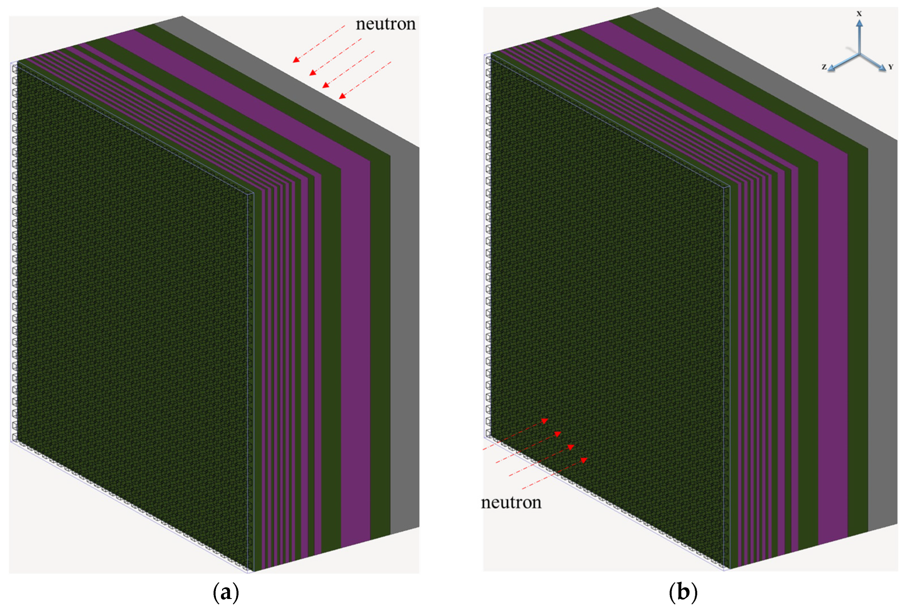
The Geant4 simulation was performed on the target [34,35]. Even though the incoming direction and angle minimally impact the interaction between the high-energy neutron and atomic nuclei, the chip’s structure varies between the top and bottom scenes. Consequently, two types of simulations were performed: one involved neutron particles striking from the passivation layer of the chip (referred to as ‘From top’ or ‘First case’), and the other entailed neutron particles incoming from the silicon substrate (referred to as ‘From bottom’ or ‘Second case’). Figure 3 illustrates the schematic of these two simulation scenarios. Except for the incoming location, all other parameters remained consistent for both simulations. Table 1 provides the architectural details of the constructed target in Geant4. It is noteworthy that the B layer above the silicon substrate, following the sequence in Table 1, served as an equivalent layer for boron contamination within the chip, as it could be introduced during the semiconductor contact and doping processes.
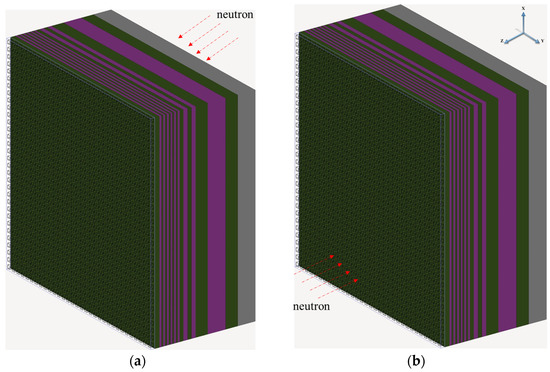
Figure 3.
Neutron impinging from top and bottom schematic diagrams, (a) from top and (b) from bottom.

Table 1.
Architectural details of the constructed target in Geant4.
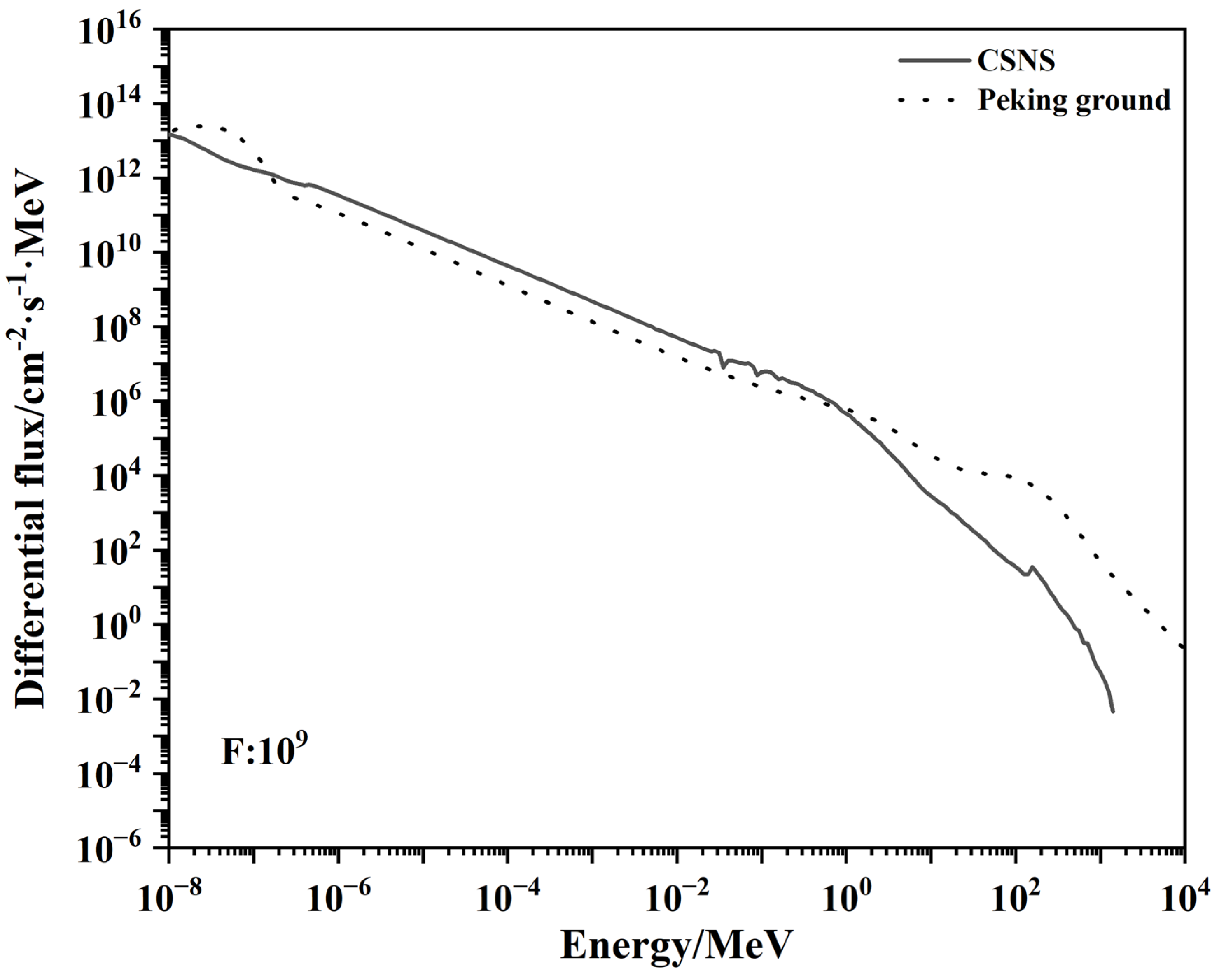
In the simulation, a 32 × 32 array of sensitive volumes was positioned, with each sensitive volume measuring 160 nm × 160 nm × 160 nm in size. The critical charge was 3820 eV. A total of 108 impinging neutrons were generated from a planar source with a size of 10,080 nm × 10,080 nm. The neutron spectrum was derived from the terminal of the China Spallation Neutron Source, as depicted in Figure 4. It can be observed that the neutron spectrum at the CSNS terminal was similar to the spectrum at ground level in Beijing, but with an amplification factor of 109 from its actual fluence.
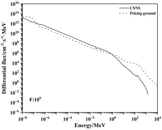
Figure 4.
The differential flux of the neutron beam at CSNS applied in Monte Carlo simulation.
5.2. Simulation Results
In the first case, a total of five SEUs were detected, while in the second case, six SEUs were detected. The details of these SEUs are listed in Table 2 and Table 3, respectively. It was observed that when the neutron struck from the top direction, a maximum of five bits were affected and experienced flipping. Conversely, when the neutron struck from the bottom direction, the number of affected bits increased to eight.
Table 2.
SEE of simulation when atmospheric neutron struck from top.
Table 3.
SEE of simulation when atmospheric neutron struck from bottom.
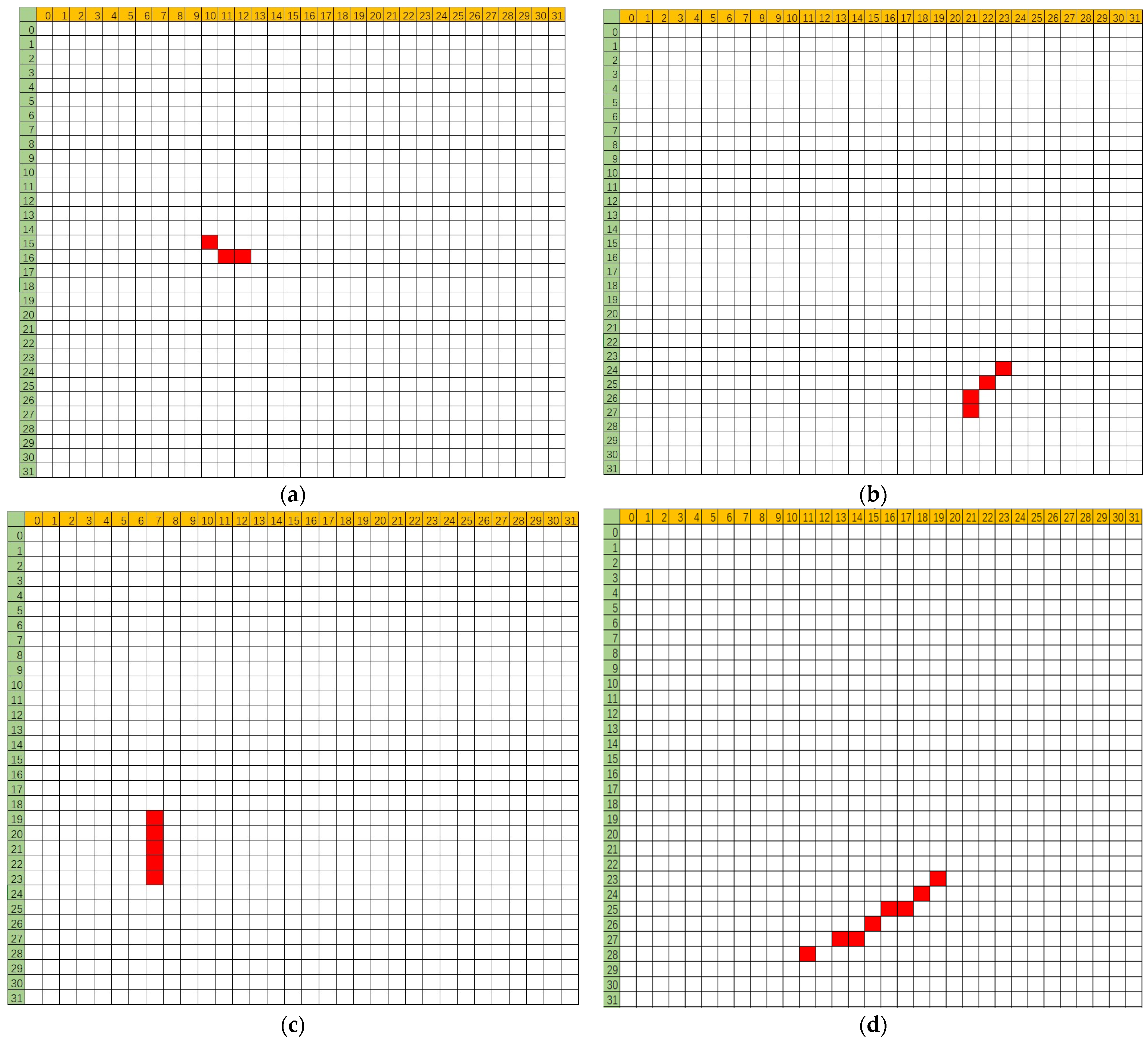
According to flipping cell coordinates, the specific distributions of these multi bit upset events could also be extracted. Figure 5 represents the flipping bit distribution schematic diagrams of a part of multi bit upset events, including three bits in (a), four bits in (b), five bits in (c), and eight bits in (d).
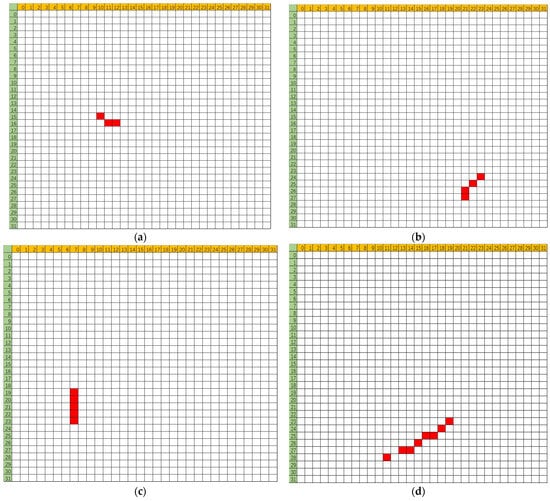
Figure 5.
Part of multi bit upset distribution, (a) three bit upset, (b) four bit upset, (c) five bit upset, (d) eight bit upset. The red stands for upset information.
Meanwhile, the percentages of different types of upset were obtained. Figure 6 depicts the proportion of them in two cases, where (a) is for the first case while (b) is for the second case.
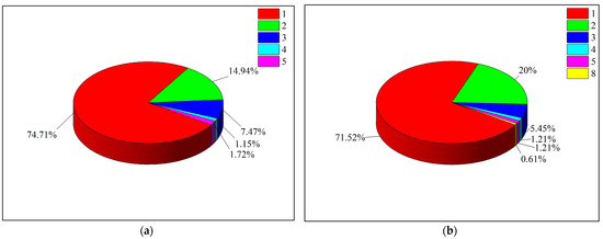
Figure 6.
Percentage of different upset in two cases, (a) first case and (b) second case.
6. Fault Injection Based on Monte Carlo Outcomes
Based on the results of the Monte Carlo simulation, more specific fault injection could be performed. During the fault injection process, the upset information aligned with the distribution and percentage detected in the Monte Carlo simulation.
6.1. Fault Injection Design
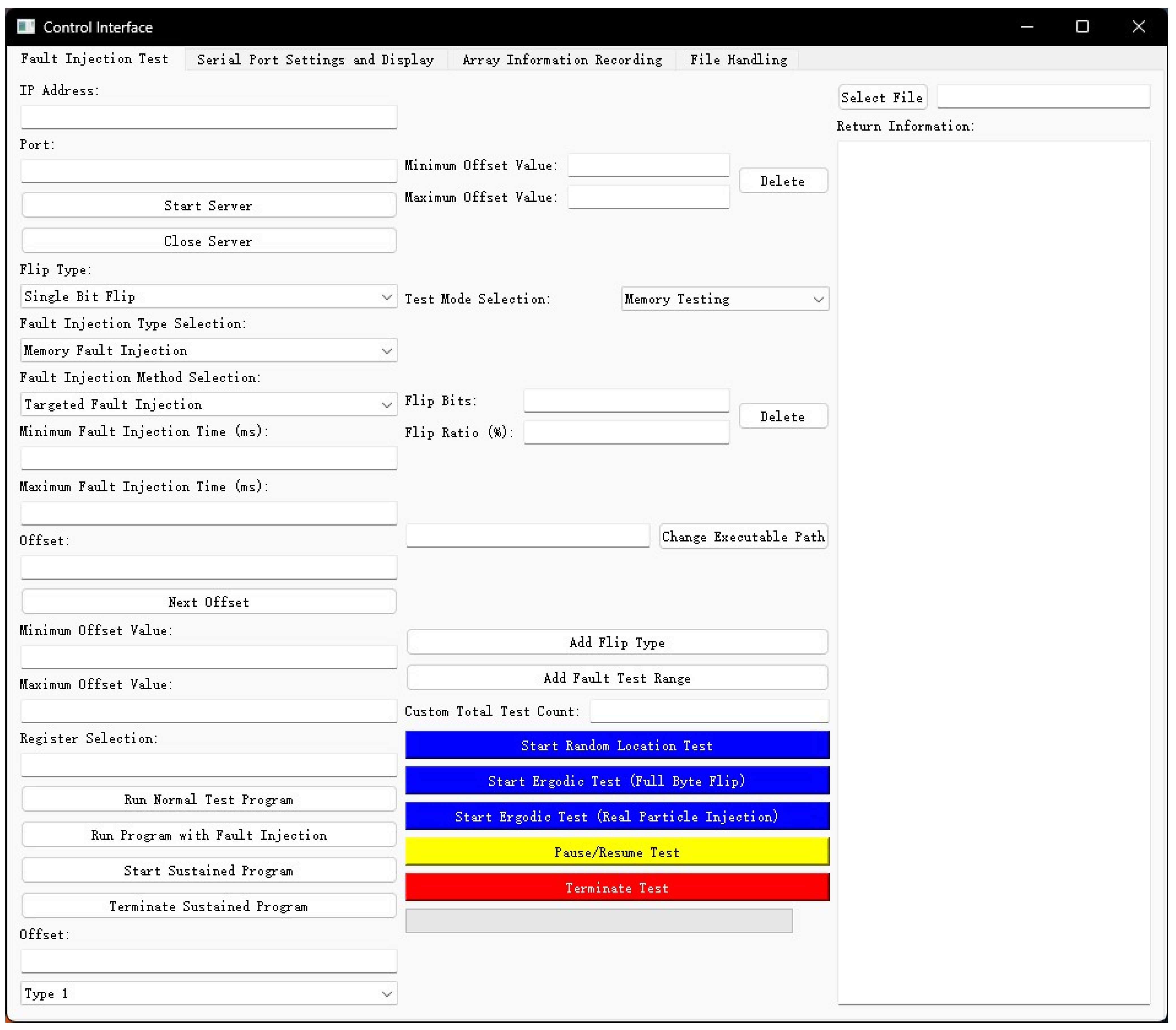
To enhance the efficiency of the fault injection software, a management terminal was developed in Python language. Figure 7 presents the graphical user interface of this terminal. Within this interface, users could input the target injection location, upset categories, and proportions for the fault injection, based on results of the Monte Carlo simulation. This information was then utilized to effectively carry out the fault injection.

Figure 7.
Window of the indigenous-designed fault injection terminal.
Three general test programs were developed by us to evaluate the performance of the relay protection Loongson 2K1000 system-on-chip development kit. These programs are as follows:
Fibonacci sequence: two sets of sequences are tested, the first set consisting of 10 terms and the second consisting of 15 terms;
Matrix Multiply: performing matrix multiplication on the two matrices [3][2] and [2][3];
Management operation: verifying if the entered username and password match the set username and password, and output the result.
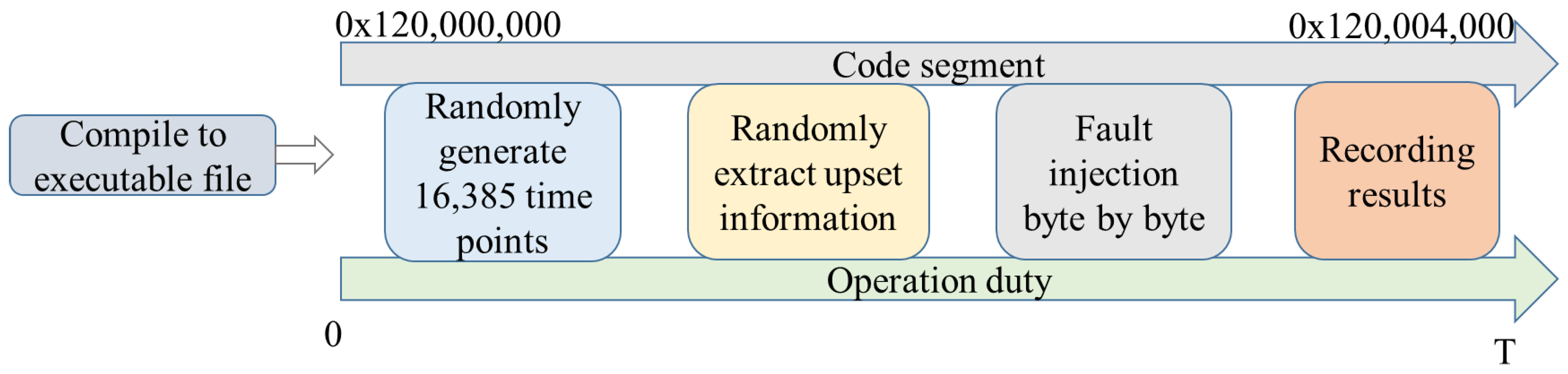
During the execution of each test program in Linux, faults were injected into the corresponding code segment. The code segment’s address ranged from 0x120,000,000 to 0x120,004,000, totaling 16,385 bytes. The details of the fault injection process were as follows, and Figure 8 depicts a diagram illustrating the fault injection.
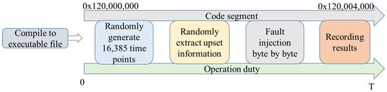
Figure 8.
Fault injection diagram.
Firstly, the test program was compiled into an executable file in the Linux environment and downloaded.
Secondly, the random injection time points were generated. Since there were 16,385 bytes in the code segment, a total of 16,385 time points were created in an operation duty for one tested program. At this point, the code segment was injected byte by byte.
Thirdly, a type of upset was extracted from the obtained flipping categories which were derived from the Monte Carlo simulation. If the upset information was extracted from the first case simulation, it corresponded to a neutron striking from the top. In contrast, if it was extracted from the second case, it represented a neutron hitting from the bottom.
Fourth, to perform a fault injection, a series of system calls were utilized. First and foremost, the fault injection program initiated a new process as a child process using the fork() system call. The child process’s ID was then retrieved. The child process took charge of interrupting, modifying, and monitoring the program under test. Then, when a specified injection time point was reached, the PTRACE() (an abbreviation of “process trace”) system call was employed to manipulate the fault injection in the child process. As a core modification method, PTRACE() allowed for bit-flip modifications in the memory corresponding to the test program’s code or data.
Lastly, it recorded the final results from the fault injection.
6.2. Fault Injection Results
Throughout the fault injection process, a total of five types of results were obtained. They included failure to execute (FE), system halt (SH), time out (TO), error result (ER) and normal. Among them, the first four soft errors were abnormal for the relay protection device. The results are defined as follows:
Failure to execute (FE): program’s exit code experiences an abnormality and cannot start to execute;
System halt (SH): program execution is halted;
Time out (TO): program execution is out of the expected duration;
Error result (ER): the execution results are different from the expected results;
Normal: the injected faults have no visible influence on the tested program’s execution.
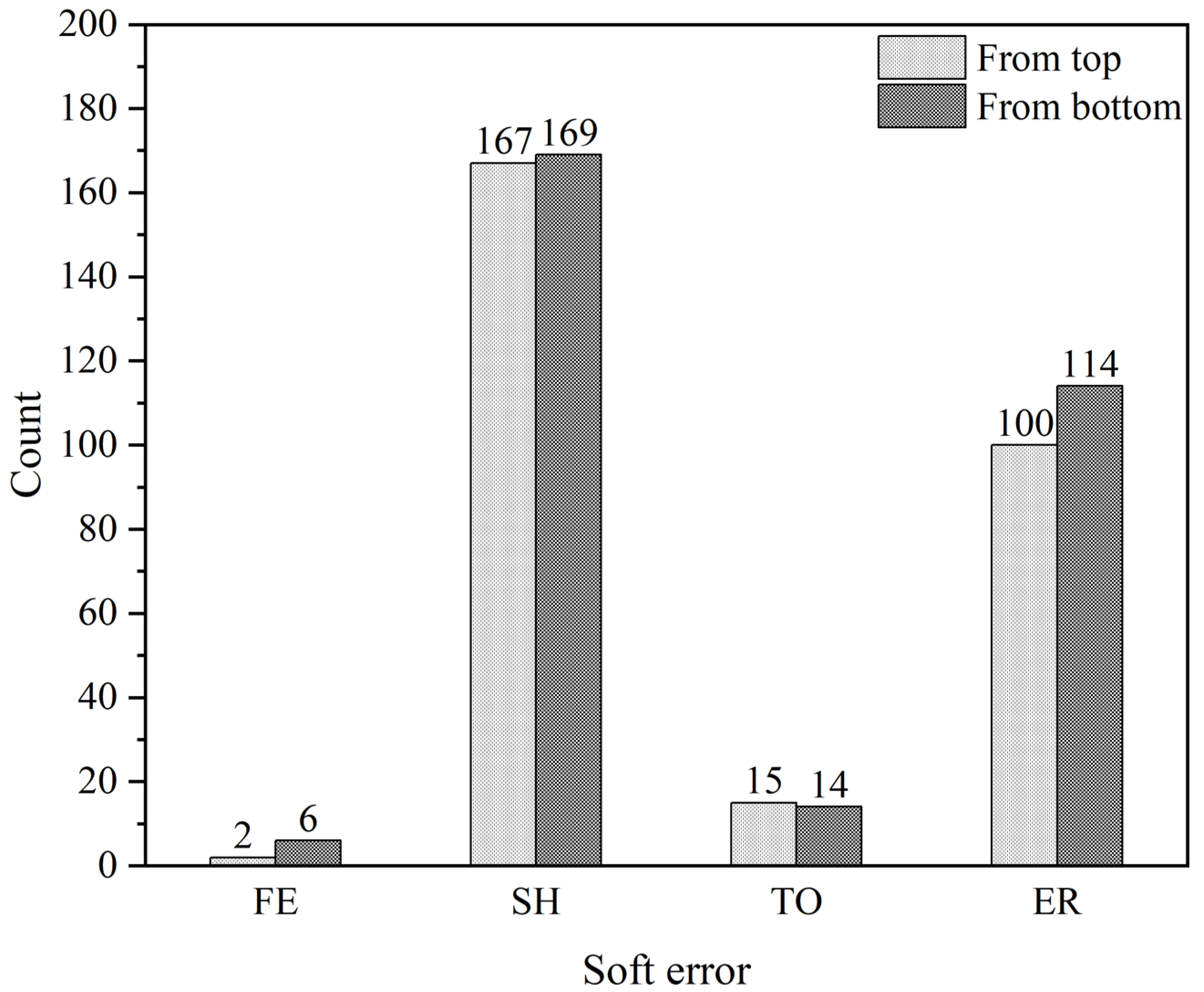
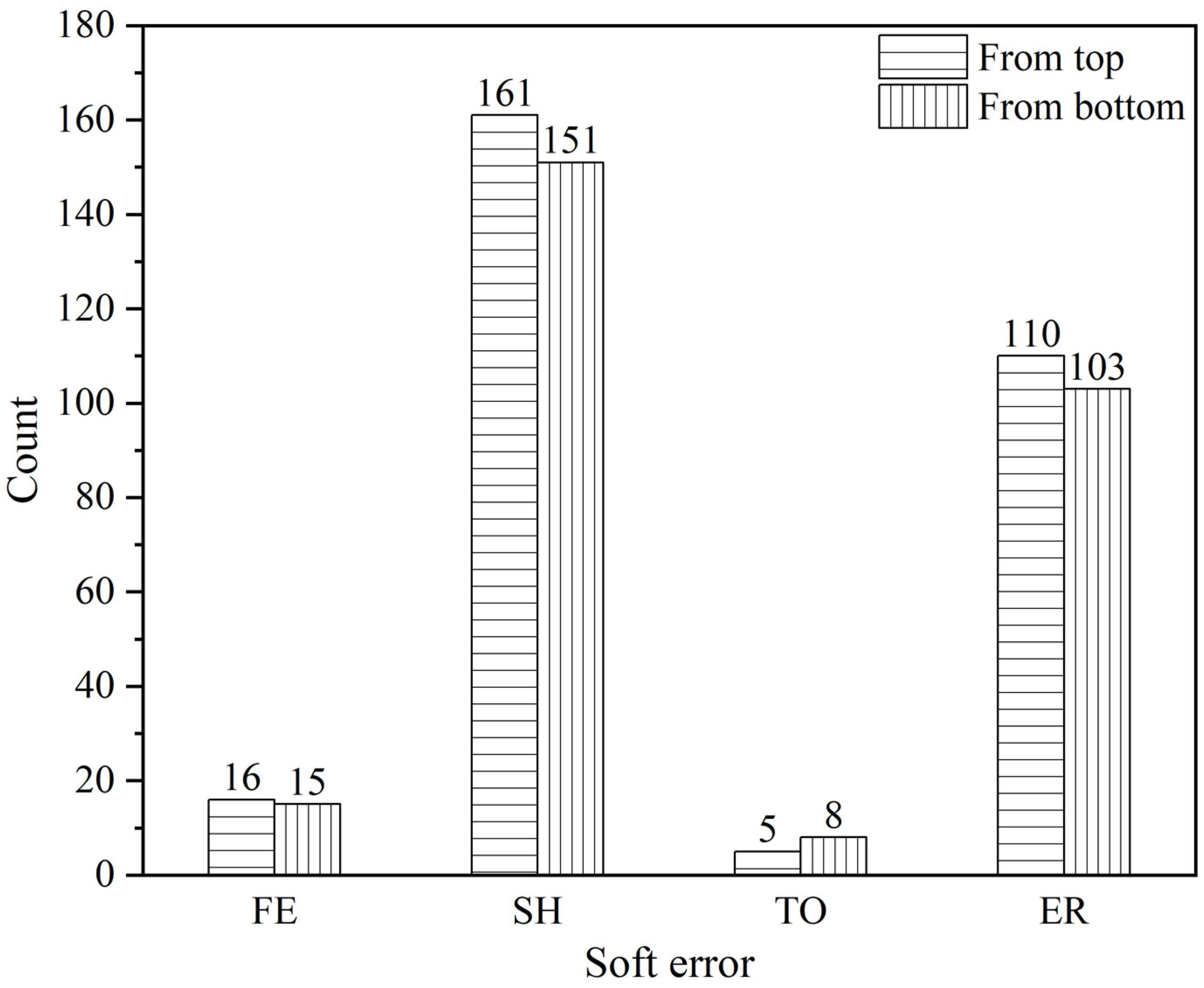
Concerning neutron striking from the top and bottom directions, the fault injection was performed for both cases. And the results for the two cases were recorded. For the Fibonacci sequence, 284 and 303 soft errors are detected based on the neutron from top and bottom striking simulation results, respectively. Figure 9 depicts the fault injection results of the Fibonacci sequence, showing that the SH and ER soft errors were much higher than FE and TO. Additionally, 546 and 552 soft errors were observed in the Matrix Multiply fault injection from the neutron top and bottom hitting simulation results. Figure 10 shows the results of the fault injection on Matrix Multiply, indicating no FE soft errors in this test. Similarly, the SH and ER soft errors were more significant. When it came to the Management operation fault injection, 292 and 277 soft errors were obtained relying on the results from the first and second case simulation, respectively. Figure 11 displays the outcomes of the Management operation fault injection, showing results similar to those of the Fibonacci sequence.

Figure 9.
Soft error in fault injection results of the Fibonacci sequence.
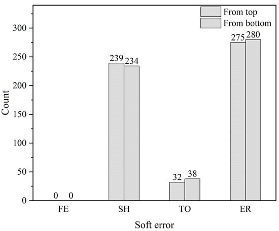
Figure 10.
Soft error in fault injection results of the Matrix Multiply.
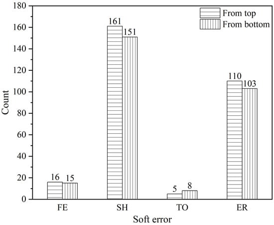
Figure 11.
Soft error in fault injection results of the Management operation.
7. Results Analysis
The atmospheric neutron spectrum encompasses a range of neutron energies from meV to GeV, including thermal (nth) and high-energy neutrons. It is important to note that born contamination is still considered to exist within advanced semiconductors, even after eliminating the boro-phospho-silicate glass packages [21,22]. This suggests that one possible cause of SEE induced by atmospheric neutrons comes from the following reactions: 10B+nth → 7Li(1.01 MeV) + α(1.78 MeV) and 10B+nth → 7Li(0.84 MeV) + α(1.47 MeV) + γ(0.48 MeV), in which the probability of the later reaction is more than 90%. Additionally, the linear energy transfers of the 7Li(0.84 MeV) and α(1.47 MeV) are 2.10 and 1.15 MeV⋅cm2⋅mg−1, respectively, which are sufficient to induce SEE within relay protection devices [21]. Another source of single event effects (SEE) arises from high-energy neutrons interacting with silicon nuclei. When an energetic neutron collides with silicon nuclei, various reactions can occur, such as Si(n, α), Si(n, p), Si(n, d), Si(n, n-α). The generated secondary energetic particles in these processes can induce SEE within relay protection devices [36].
From the obtained results in Table 2 and Table 3, it can be observed that neutrons striking from the top or bottom of the chip can result in multiple types of SEU. Further, the cross section for the first case was 2.42 × 10⁻¹⁵ cm2⋅bit−1 while for the second case was 2.35 × 10⁻¹⁵ cm2⋅bit−1. These are close to the results obtained in spallation neutron source irradiation on similar technology memory. In the irradiation test, the SEE cross section was 1.50 × 10⁻¹⁵ cm2⋅bit−1 [37]. It demonstrates that the Monte Carlo simulation and the fault injection results are credible. Meanwhile, the soft error rate for them at Beijing ground (9.5 n/(cm2·h)) were 22.99 and 22.33 FIT/Mbit when neutrons struck from top and bottom, respectively. These indicate that the SEE sensitivity of relay protection devices are almost close whether a neutron hits from the top or bottom.
Furthermore, Figure 9, Figure 10 and Figure 11 show that soft errors occur in proximity to each other when neutrons strike from the top or bottom in each test program. This suggests that the discrepancy in SEE influence between neutrons hitting from the top and bottom is minimal. The results indicate the need for solutions to mitigate SEE on relay protection devices in the current and near future, such as the error correcting code in memory, the redundancy in data and code, the rollback examination in software, lockstep in dual cores, or others.
Although these findings regarding single event effects and soft errors derived from atmospheric neutron studies, it is reasonable to speculate that they can be applied to the evaluation of SEE induced by energetic protons in space. This suggests that when energetic protons impact the chip from both the top and bottom in aerospace applications, the resulting SEE sensitivity and occurrence of soft errors may be relatively similar under these two conditions.
From Figure 6, it can be observed that single bit upsets account for about 70% of flipping. For these single bit upsets, they can be addressed by techniques, such as error checking code. More seriously, this means almost 30% of upsets are difficult to mitigate. This also indicates much more SEE research on relay protection devices is required.
In the fault injection results of different test programs, a common phenomenon is that the number of “SH” and “ER” exceeds that of “TO” and “FE”. Software fault injection simulates soft errors caused by bit flips during program execution, resulting in data or instruction errors. These errors can lead to outcomes such as the loss of data integrity, alteration of instruction flow, and triggering of exception signals. Among these, abnormal exit status codes (FE) often occur when soft errors cause the program to jump to incorrect code paths or error handling routines, while timeout (TO) is caused by the program entering into an unintended, prolonged wait state or getting caught in a loop condition. These two outcomes typically occur when soft errors do not compromise data integrity, trigger exception signals, or lead to broader errors. Therefore, the majority of soft errors are more likely to cause program execution halting (SH) or error results (ER).
The main objective of this research is to preliminarily assess the impact of SEE induced soft errors on relay protection devices in China using spallation neutron source, which has been successfully achieved. Although energy levels above 1 MeV or 10 MeV are usually used to evaluate SEE in atmospheric neutron irradiation, the contribution of thermal neutrons to SEE in advanced technology relay protection devices remains unclear. In the future, by leveraging thermal neutron absorptions or other techniques, we can further evaluate the relative contributions of different energy levels of neutrons from atmospheric neutron to SEE and soft errors in relay protection devices.
8. Conclusions
Atmospheric neutrons are confirmed to induce soft errors in relay protection devices using China spallation neutron source irradiation. For the core processor of the relay protection Loongson 2K1000 system-on-chip, the Monte Carlo simulation was performed and single event effects were obtained when neutrons struck from the top and bottom of the chip. Simulation results demonstrated that the single event effect vulnerability was close for neutrons hitting from the top and bottom. The fault injection was performed on three general test programs relying on the single event upset information from Monte Carlo simulations. Soft errors, including failure to execute, system halt, time out, and error result were obtained and the occurrence of system halts and error results were higher than failures to execute and time outs. The fault injection results mean that the effects are almost the same for the relay protection device when a neutron hits from the top or bottom.
Author Contributions
Conceptualization, H.Z., W.Y. and C.H.; methodology, H.Z. and Z.Z.; software, H.Y.; validation, Z.S.; formal analysis, Q.Z.; resources, H.Z.; writing—original draft preparation, W.Y. and H.Z. All authors have read and agreed to the published version of the manuscript.
Funding
Project supported by the Science and Technology Project of NARI Technology Co., Ltd. (Grant No. SGNRGF00XAJS2301697) and the National Natural Science Foundation of China (Grant Nos. 11835006, 11690040, and 11690043).
Data Availability Statement
The data used to support the findings of this study are available from the corresponding author upon request.
Acknowledgments
Thanks for the support from the NARI Group Corporation (State Grid Electric Power Research Institute), and NARI Technology Co., Ltd.
Conflicts of Interest
The authors H. Zhou, Z. Zou, Z. Su, and Q. Zhao were employed by the company NARI Group Corporation (State Grid Electric Power Research Institute), and NARI Technology Co., Ltd. The remaining authors declare that the research was conducted in the absence of any commercial or financial relationships that could be construed as a potential conflict of interest.
References
- Tian, M.; Zhang, L.; Guo, P.; Zhang, H.; Chen, Q.; Li, Y.; Xue, A. Data dependence analysis for defects data of relay protection devices based on apriori algorithm. IEEE Access 2020, 8, 120647–120653. [Google Scholar] [CrossRef]
- Zhang, B.; Hao, Z.; Bo, Z. New development in relay protection for smart grid. Prot. Control. Mod. Power Syst. 2016, 1, 14. [Google Scholar] [CrossRef]
- Wang, J.F.; Yang, P.W.; Chen, X.L. State evaluation of relay protection system for state maintenance. IOP Conf. Ser. Earth Environ. Sci. 2019, 354, 012120. [Google Scholar] [CrossRef]
- Esfahani, M.M.; Mohammed, O. An intelligent protection scheme to deal with extreme fault currents in smart power systems. Electr. Power Energy Syst. 2020, 115, 105434. [Google Scholar] [CrossRef]
- Kiliçkiran, H.C.; Şengör, İ.; Akdemir, H.; Kekezoğlu, B.; Erdinç, O.; Paterakis, N.G. Power system protection with digital overcurrent relays: A review of nonstandard characteristics. Electr. Power Syst. Res. 2018, 164, 89–102. [Google Scholar] [CrossRef]
- Zamani, M.A.; Sidhu, T.S.; Yazdani, A. A protection strategy and microprocessor-based relay for low-voltage microgrids. IEEE Trans. Pow. Deliv. 2011, 26, 1873–1883. [Google Scholar] [CrossRef]
- Wei, D.; Lu, Y.; Jafari, M.; Skare, P.M.; Rohde, K. Protecting Smart Grid Automation Systems Against Cyberattacks. IEEE Trans. Smart Grid 2011, 2, 782–795. [Google Scholar] [CrossRef]
- Liang, W.; Ouyang, F.; Wang, S.; Zhu, W.; Li, G. Smart Operation and Maintenance Platform of Protection Relay Based on Mobile Sensing and Big Data. IOP Conf. Ser. Earth Environ. Sci. 2021, 632, 042021. [Google Scholar] [CrossRef]
- Luza, L.M.; Wrobel, F.; Entrena, L.; Dilillo, L. Impact of Atmospheric and Space Radiation on Sensitive Electronic Devices. In Proceedings of the IEEE European Test Symposium, Barcelona, Spain, 23–27 May 2022. [Google Scholar]
- Reed, R.A.; Kinnison, J.; Pickel, J.C.; Buchner, S.; Marshall, P.W.; Kniffin, S.; LaBel, K.A. Single-event effects ground testing and on-orbit rate prediction methods: The past, present, and future. IEEE Trans. Nucl. Sci. 2003, 50, 622–634. [Google Scholar] [CrossRef]
- Liu, H.; Zhang, Y.; Li, W.; Zhang, X.; Wang, H. Research on the influence and test of core components on relay protection device. IOP Conf. Ser. Earth Environ. Sci. 2021, 631, 012089. [Google Scholar] [CrossRef]
- Li, Y.; Zhi, L.H.; Ping, L.D.; Bo, Z.H.; Zhang, L.; Hua, T.X. Analysis of interference factors of relay protection devices in high altitude areas and research on solutions. Rev. Adhes. Adhes. 2023, 11, 125–139. [Google Scholar]
- Ngo, M.; Nguyen, H.; Dinh, T. A study of SVC’s impact simulation and analysis for distance protection relay on transmission lines. Int. J. Electr. Comput. Eng. 2017, 7, 1686–1695. [Google Scholar]
- Ji, B.; Yang, X.; Liu, C.; Xu, H.; Ji, Y.; Tao, S. Develop a test device to check the charged relay protection. In Proceedings of the 2021 IEEE International Conference on Power, Intelligent Computing and Systems, Shenyang, China, 29–31 July 2021. [Google Scholar]
- Dikarev, P.V.; Shilin, A.A.; Ahmedova, O.O. Circuit breaker control of intelligent relay protection system. In Proceedings of the 2021 International Conference on Industrial Engineering, Applications and Manufacturing, Sochi, Russia, 17–21 May 2021. [Google Scholar]
- Zhang, H.; Liu, Z.; Fan, Z.; Song, H.; Niu, Z.; Xiong, Z.; Deng, M.; Shuai, J.; Li, W.; Li, X. Failure causes and solutions of relay protection switching power supply. J. Phys. Conf. Ser. 2022, 2196, 012039. [Google Scholar] [CrossRef]
- Ying, L.; Jia, Y.; Li, W. Research on state evaluation and risk assessment for relay protection system based on machine learning algorithm. IET Gener. Transm. Distrib. 2020, 14, 3619–3629. [Google Scholar] [CrossRef]
- Chen, Q.; Zhang, L.; Guo, P.; Zhang, H.; Tian, M.; Li, Y.; Xue, A. Modeling and Analysis of Incorrect Actions of Relay Protection Systems Based on Fault Trees. IEEE Access 2020, 8, 114571–114579. [Google Scholar] [CrossRef]
- Haas, D.; Zimmerman, K. Single Event Upsets in SEL Relays. March 2018. Available online: https://selinc.com (accessed on 5 May 2023).
- Zimmerman, K.; Haas, D. Impacts of single event upsets on protective relays. In Proceedings of the 72nd Annual Conference for Protective Relay Engineers, College Station, TX, USA, 25–28 March 2019. [Google Scholar]
- Yang, W.; Li, Y.; Li, Y.; Hu, Z.; Cai, J.; He, C.; Wang, B.; Wu, L. Neutron Irradiation Testing and Monte Carlo Simulation of a Xilinx Zynq-7000 System on Chip. Electronics 2023, 12, 2057. [Google Scholar] [CrossRef]
- Weulersse, C.; Houssany, S.; Guibbaud, N.; Segura-Ruiz, J.; Beaucour, J.; Miller, F.; Mazurek, M. Contribution of Thermal Neutrons to Soft Error Rate. IEEE Trans. Nucl. Sci. 2018, 65, 1851–1857. [Google Scholar] [CrossRef]
- Li, Y.; Zhou, H.; Zheng, Y. Error-tolerant Design and Application of Relay Protection Device against Unexpected Memory Bit Change. Autom. Electr. Power Syst. 2021, 45, 155–162. (In Chinese) [Google Scholar]
- Hao, Z.; Lei, S.; Tao, P.; Songze, L. Analysis and countermeasures of single event upset soft errors in a relay protection device. Power Syst. Prot. Control. 2021, 49, 144–149. (In Chinese) [Google Scholar]
- NARI Group Corporation Brief Introduction. Available online: https://www.china-power-contractor.cn/NARI-Group-Corporation-brief-introduction.html (accessed on 12 July 2023).
- Andreani, C.; Senesi, R.; Paccagnella, A.; Bagatin, M.; Gerardin, S.; Cazzaniga, C.; Frost, C.D.; Picozza, P.; Gorini, G.; Mancini, R.; et al. Fast neutron irradiation tests of flash memories used in space environment at the ISIS spallation neutron source. AIP Adv. 2018, 8, 025013. [Google Scholar] [CrossRef]
- Chen, H.; Chen, Y.; Wang, F.; Liang, T.; Jia, X.; Ji, Q.; Hu, C.; He, W.; Yin, W.; He, K.; et al. Target station status of China Spallation Neutron Source. Neutron News 2018, 29, 2–6. [Google Scholar] [CrossRef]
- Tang, J.; Liu, R.; Zhang, G.; Ruan, X.; Wu, X.; An, Q.; Bai, J.; Bao, J.; Bao, Y.; Cao, P.; et al. Initial years’ neutron-induced cross-section measurements at the CSNS Back-n white neutron source. Chin. Phys. C 2021, 45, 062001. [Google Scholar] [CrossRef]
- Yang, W.; Li, Y.; He, C. Fault injection and failure analysis on Xilinx 16 nm FinFET Ultrascale+ MPSoC. Nucl. Eng. Technol. 2022, 54, 2031–2036. [Google Scholar] [CrossRef]
- Loongson. Loongson 2K1000 Processor User Manual v1.4; Loongson: Beijing, China, 2021. [Google Scholar]
- De Sio, C.; Azimi, S.; Sterpone, L.; Codinachs, D.M. Analysis of Proton-induced Single Event Effect in the On-Chip Memory of Embedded Processor. In Proceedings of the 2022 IEEE International Symposium on Defect and Fault Tolerance in VLSI and Nanotechnology Systems (DFT), Austin, TX, USA, 19–21 October 2022. [Google Scholar]
- Koga, R.; George, J.; Bielat, S. Single Event Effects Sensitivity of DDR3 SDRAMs to Protons and Heavy Ions. In Proceedings of the 2012 IEEE Radiation Effects Data Workshop, Miami, FL, USA, 16–20 July 2012. [Google Scholar]
- Wei, J.; Fang, S.; Cao, J.; Chi, Y.; Deng, C.; Dong, H.; Dong, L.; Fu, S.; Kang, W.; Li, J.; et al. China spallation neutron source: Accelerator design iterations and R&D status. J. Korean Phys. Soc. 2007, 50, 1377–1384. [Google Scholar]
- Agostinelli, S.; Allison, J.; Amako, K.A.; Apostolakis, J.; Araujo, H.; Arce, P.; Asai, M.; Axen, D.; Banerjee, S.; Barrand, G.J.N.I.; et al. GEANT4-a simulation toolkit. Nucl. Instrum. Methods Phys. Res. A 2003, 506, 250–303. [Google Scholar] [CrossRef]
- Yang, W.; Li, Y.; Zhang, W.; Guo, Y.; Zhao, H.; Wei, J.; Li, Y.; He, C.; Chen, K.; Guo, G.; et al. Electron inducing soft errors in 28 nm system-on-Chip. Radiat. Eff. Defects Solids 2020, 175, 745–754. [Google Scholar] [CrossRef]
- Casolaro, P.; Campajola, L.; De Luca, D. Neutrons for studies of radiation hardness. Il Nuovo Cimento C 2020, 43, 57. [Google Scholar]
- Yang, W.; Li, Y.; Li, Y.; Hu, Z.; Xie, F.; He, C.; Wang, S.; Zhou, B.; He, H.; Khan, W.; et al. Atmospheric neutron single event effect test on Xilinx 28 nm system on chip at CSNS-BL09. Microelec. Reliab. 2019, 99, 119–124. [Google Scholar] [CrossRef]


Disclaimer/Publisher’s Note: The statements, opinions and data contained in all publications are solely those of the individual author(s) and contributor(s) and not of MDPI and/or the editor(s). MDPI and/or the editor(s) disclaim responsibility for any injury to people or property resulting from any ideas, methods, instructions or products referred to in the content. |
© 2023 by the authors. Licensee MDPI, Basel, Switzerland. This article is an open access article distributed under the terms and conditions of the Creative Commons Attribution (CC BY) license (https://creativecommons.org/licenses/by/4.0/).