Communication

Pre-Design of Multi-Band Planar Antennas by Artificial Neural Networks

1
National Institute of Applied Sciences and Technology, Tunis 625 00, Tunisia
2
Faculty of Electrical Engineering and Communication, Brno University of Technology, Brno-Královo Pole, 616 00 Brno, Czech Republic
3
Faculty of Military Technology, University of Defence, Brno-Střed, 662 10 Brno, Czech Republic
*
Author to whom correspondence should be addressed.
Electronics 2023, 12(6), 1345; https://doi.org/10.3390/electronics12061345
Submission received: 13 February 2023 / Revised: 3 March 2023 / Accepted: 10 March 2023 / Published: 12 March 2023

Abstract

:
In this communication, artificial neural networks are used to estimate the initial structure of a multiband planar antenna. The neural networks are trained on a set of selected normalized multiband antennas characterized by time-efficient modal analysis with limited accuracy. Using the Deep Learning Toolbox in Matlab, several types of neural networks have been created and trained on the sample planar multiband antennas. In the neural network learning process, suitable network types were selected for the design of these antennas. The trained networks, depending on the desired operating bands, will select the appropriate antenna geometry. This is further optimized using Newton’s method in HFSS. The use of the neural pre-design concept speeds up and simplifies the design of multiband planar antennas. The findings presented in this paper will be used to refine and accelerate the design of planar multiband antennas.

1. Introduction

When designing a conventional multi-band planar antenna, a proper patch geometry has to be selected to obtain resonant frequencies in the requested operational bands [1]. In the next step, a full-wave numerical model of the antenna is developed in an electromagnetic simulator, and the model is optimized to meet the required parameters of the antenna as accurately as possible.
A proper antenna geometry is selected by a designer experienced with it. In this communication, we train artificial neural networks (ANN) to represent the designer’s experience. ANNs are trained on a set of normalized multi-band antennas characterized by modal analysis, which efficiently produces approximate training patterns. The modal analysis itself and the way of creating training sets are described in Section 2.1.
When designing a planar antenna on a prescribed substrate for requested operation bands, normalization related to the wavelength in the substrate is performed, and normalized resonant frequencies are mapped by ANN to the optimum antenna geometry. For mapping, three types of ANN are used:
  • Feed-forward back-propagation ANN [2].
  • Cascade-forward back-propagation ANN [3].
  • Probabilistic ANN [4].
In Section 2.2, ANN are briefly introduced, and the process of their training is described.
In Section 3, we present a design example to illustrate the functionality of the neural pre-design. Section 4 concludes the paper.
In the open literature, several papers on an ANN-enhanced antenna design have been published. The papers cover the following topics:
  • On-line neural synthesis of radiation patterns. In an article about the design of a cognitive antenna array [5], the radiation pattern of a conformal patch array has been adapted to a complex environment by a proper phasing of elements. A used deep reinforcement learning was based on an on-line network, which updated parameters for training, and a target network, which calculated the loss function exploiting data from an experience pool. In a paper investigating the synthesis of conformal phased array antenna (PAA) patterns using deep synthesis [6], the on-line ANN and the target ANN created a tandem network structure that minimized the difference between the requested pattern and the current one.
In the described approaches, antenna geometries are fixed, and input signals are optimized to reach requested radiation patterns. In this communication, the neural network selects the optimum shape of the patch to form the optimum current distribution related to multiple resonances in the requested operational bands.
  • Black-box modeling of antenna structures. Computer processing unit (CPU)-time moderate ANNs are trained to approximate the results of CPU-time expansive full-wave analysis over a limited definition space. This approach can be applied both to canonical structures [7] and advanced ones. A patch antenna with a ground plane defected by split-ring resonators was modeled by a multi-layer perceptron and optimized by a particle swarm algorithm in [8]. A high-gain quasi-Yagi antenna with a parabolic reflector was modeled by a pyramidal deep regression network in [9].
For multi-physics modeling of microwave filters, the authors used a deep hybrid neural network [10]. The network was conceived as a cascade of ANNs with different parameters. For resonant structures like filters, this modeling approach was shown to be beneficial.
Neural black-box models usually face the problem of sufficient generality and acceptable accuracy being reached with reasonable efforts [11]. A sufficiently general model should cover a sufficiently large definition space of an optimum dimension, which is given by the number of state variables. A sufficiently accurate model usually requires time-expansive simulations of training patterns.
In order to overcome these difficulties, we propose an approximate classifier that maps normalized operation frequencies to the optimum layout of an antenna element. The definition space is reduced by working with normalized frequencies and dimensions, and the CPU time needed to create training sets is minimized by using a time-moderate modal analysis. If the pre-designed structure is sufficiently accurate, then conventional local optimization can be quick and inexpensive.
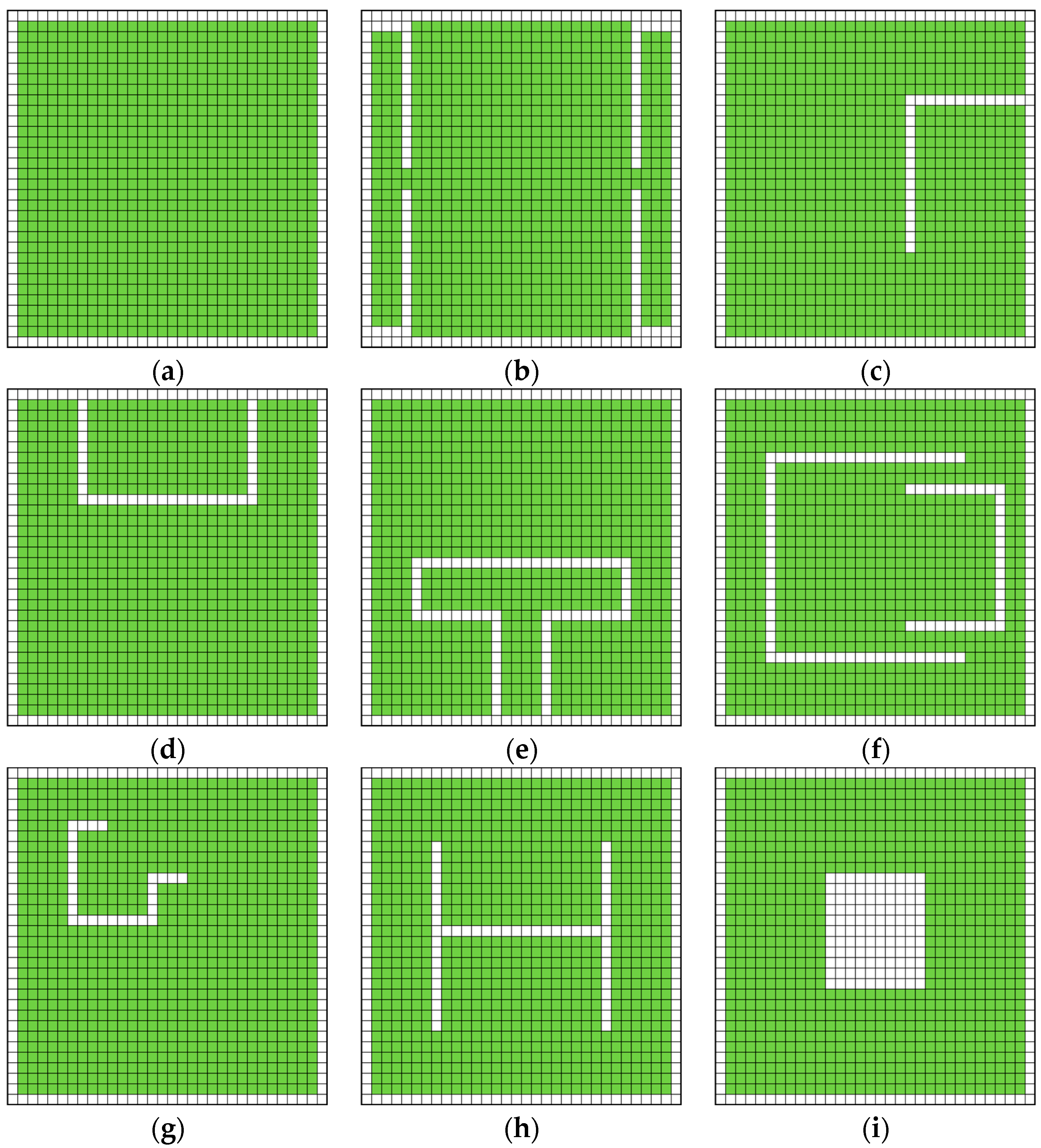
  • Antenna design by ANN and optimizer. If the efficient and accurate black-box model is completed by an optimization algorithm, a simple design tool can be developed. In [12], a patch is divided into pixels. The shape of the patch is synthesized by combining a convolutional ANN in the role of a forward model (geometry at the input and performance at the output) and a genetic algorithm in the role of the optimizer.
The described approach can be used even for a multi-objective design of antennas. In [13], a deep neural model was combined with Thomson sampling for efficient multi-objective optimization to reveal the Pareto front of optimal solutions.
In [14], planar ultra-wideband antennas were designed by combining deep structures (the cascade of an extreme learning machine, a deep belief network, and a restricted Boltzmann machine) and a particle swarm optimization as a global optimizer.
Since properly trained ANNs can provide the response very quickly (only a few arithmetic operations are needed to be executed in parallel), neural models are advantageous when combined with evolutionary algorithms [15,16], swarm-intelligence approaches [17,18], and other CPU-time expensive global optimizers. But the question of the development of a sufficiently general and sufficiently accurate neural model remains.
The approach presented in this communication is based on neural classifiers. A pure classification of planar microwave filters was presented in [19]. At the input of a deep network, a bitmap with a photo of the filter was introduced. ANN classified the filter as a low-pass or band-pass one and determined the order of the filter.
In [20], the classifier considered the requested gain, impedance bandwidth, and operation frequency and selected among a patch antenna, a spiral antenna, or a horn antenna. Then, the selected antenna was designed by an inverse neural model that mapped requested antenna parameters to antenna dimensions. Antenna geometries were given, and dimensions were computed.
In the presented approach, the operational frequencies of a planar multiband antenna are mapped by the trained neural network to the optimum normalized geometry of the patch. Consecutively, the selected geometry is modeled in the High Frequency Structure Simulator (HFSS) and optimized by the Newton algorithm. Thanks to the successful pre-design, the local optimization is sufficient, and a low number of iteration steps is required.
This provides further acceleration of the antenna structure design. According to our knowledge, the described exploitation of ANN for the antenna pre-design has not been presented in the open literature yet.

2. Methods

We intend to create an efficient tool for the design of planar multi-band antennas. In order to ensure a sufficient design efficiency, we use a classifier for the selection of an optimal normalized antenna geometry, which is the first step. Second, the geometry is denormalized, taking into account the wavelength of the used substrate, and a full-wave HFSS model is developed. Finally, the model is optimized by the local Newton optimizer in a few steps.
In the following paragraphs, the individual design steps are described in detail.

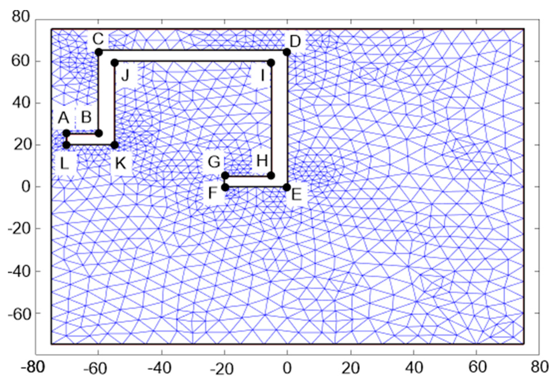
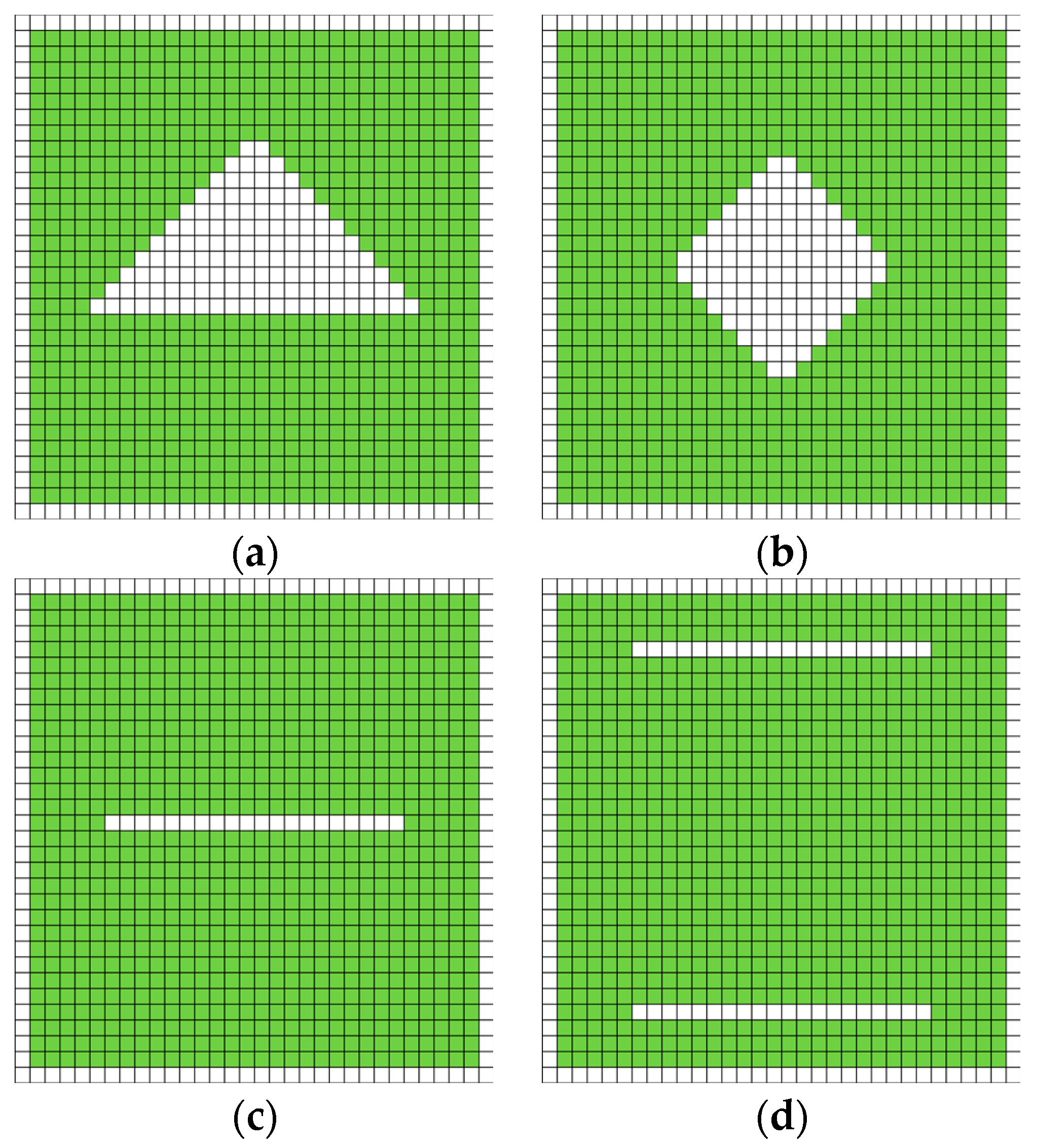
2.1. Training Sets by Modal Analysis

The normalized antenna geometries consider an air substrate with the dielectric constant εr = 1, negligible loss tan δ = 0, and a thickness of h = 1 mm. Since the corresponding wavelength is λ0 = 300 mm, we create a set of slotted patches with the fundamental dimension 150 mm × 150 mm.
Geometries of training patterns are depicted in Figure 1, with pixel dimensions of 5 mm × 5 mm. The green pixels represent metallization (a perfect electric conductor in an approximation, a standard copper foil in an implementation), and the white pixels represent an uncovered substrate.
The size of the patch is fixed at 30 × 30 pixels except for the extended patch antenna (Figure 1b). The width of slots is fixed at 1 pixel, except for the square slot (Figure 1i).
Training geometries are going to cover the most important mechanisms of exciting multi-band behavior:
  • The conventional patch (Figure 1a) plays the role of reference. The multi-band behavior corresponds to the higher modes of the patch. The extended patch antenna (Figure 1b) can be understood as a conventional patch with a capacitive prolongation [21].
  • The L-slot antenna (Figure 1c) represents patches with a two-segment slot that breaks the patch edge into two parts. The currents in both sub-areas of the patch are galvanically connected [21].
  • The U-slot antenna (Figure 1d) represents patches with a three-segment slot that breaks the patch edge into two parts. The currents in both sub-areas of the patch are separated [21].
  • The T-slot antenna (Figure 1e) can be understood as a folded slot dipole fed by a coplanar waveguide (CPW) [22]. A magnetic current flowing in the slot loop is the source of the radiation.
The double-U antenna, the G antenna, and the H antenna are patches with slots inside the antenna element. These slots directly influence the current distribution on the patch and the multiband behavior of the patch. The double-U antenna (Figure 1f) consists of a large radiator (the whole patch) and a small one (the area inside slots), which define two operational bands [21]. The G antenna (Figure 1g) divides the patch into an internal area and two external ones, potentially offering a triple-band operation [23]. In the case of a non-symmetrically located non-symmetrical H slot (Figure 1h), more than three bands can be created [24]. Finally, a square slot (Figure 1i) creates the equivalent of a loop antenna [25].
With varying positions and dimensions of slots, 60 training layouts were created. Each layout was modeled in the partial differential equation (PDE) tool of MATLAB [26]:
  • Metallic parts of the layout were enclosed by Neumann boundary conditions.
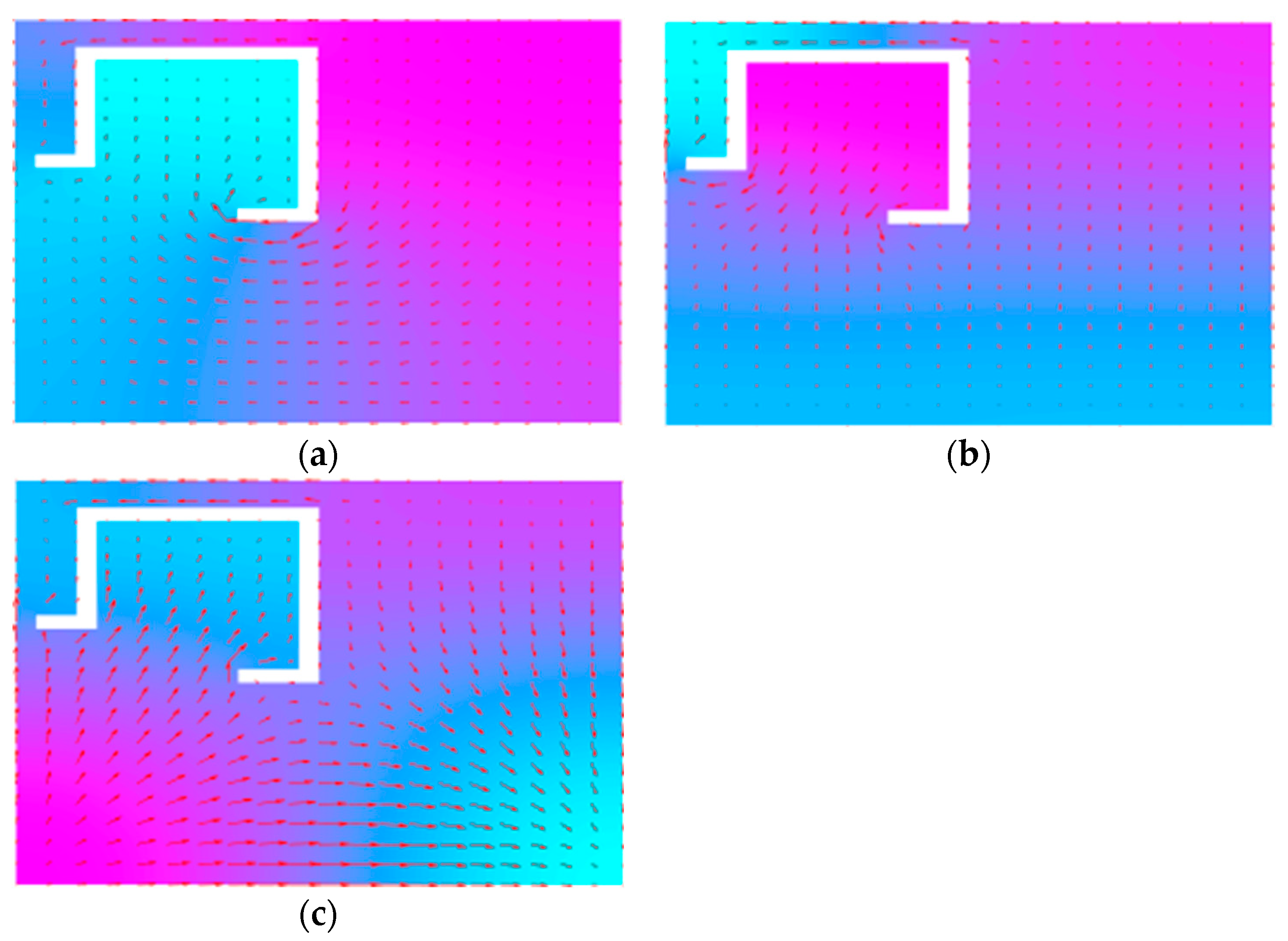
  • The solver was set to evaluate eigenmodes.
  • Eigenvalues were considered within the interval <0; 5 × 10⁴>.
Since eigenvalues are equal to the squared wave number, the operational frequencies of antennas can be evaluated according to [27]:
f n = c 2 π a n
where fn is the n-th resonant frequency of the antenna, corresponding to the n-th eigenvalue an computed by the PDE tool, and c is the velocity of light in vacuum.
The numerical model of the G-slot patch is depicted in Figure 2. Boundaries (black lines) are associated with the Neumann boundary condition. The dimensions of the patch are fixed. Position and dimensions of the slot are varied by changing the coordinates of polygon vertices A through L.
The three lowest modes computed by the PDE tool (Figure 3) were used to compose a training pattern. Other training patterns were prepared in a similar way.
As a result, we have 60 triplets of resonant frequencies for 60 patch layouts. Neural networks are trained to map triples of frequencies on the input to the index of a corresponding patch layout on the output. Details are given in the next paragraph.

2.2. ANN and Training Process

We use neural networks to map triplets of resonant frequencies computed by the modal analysis to the index of a corresponding patch layout. Hence, the networks have three neurons in the input layer and a single neuron in the output layer. The input neurons simply distribute signals to neurons in the hidden layer. The output neuron collects signals from neurons in the hidden layer and processes the signal using the activation function [1].
In order to select optimal patch layouts, we used 3 ANNs from the Deep Learning Toolbox of MATLAB [28]:
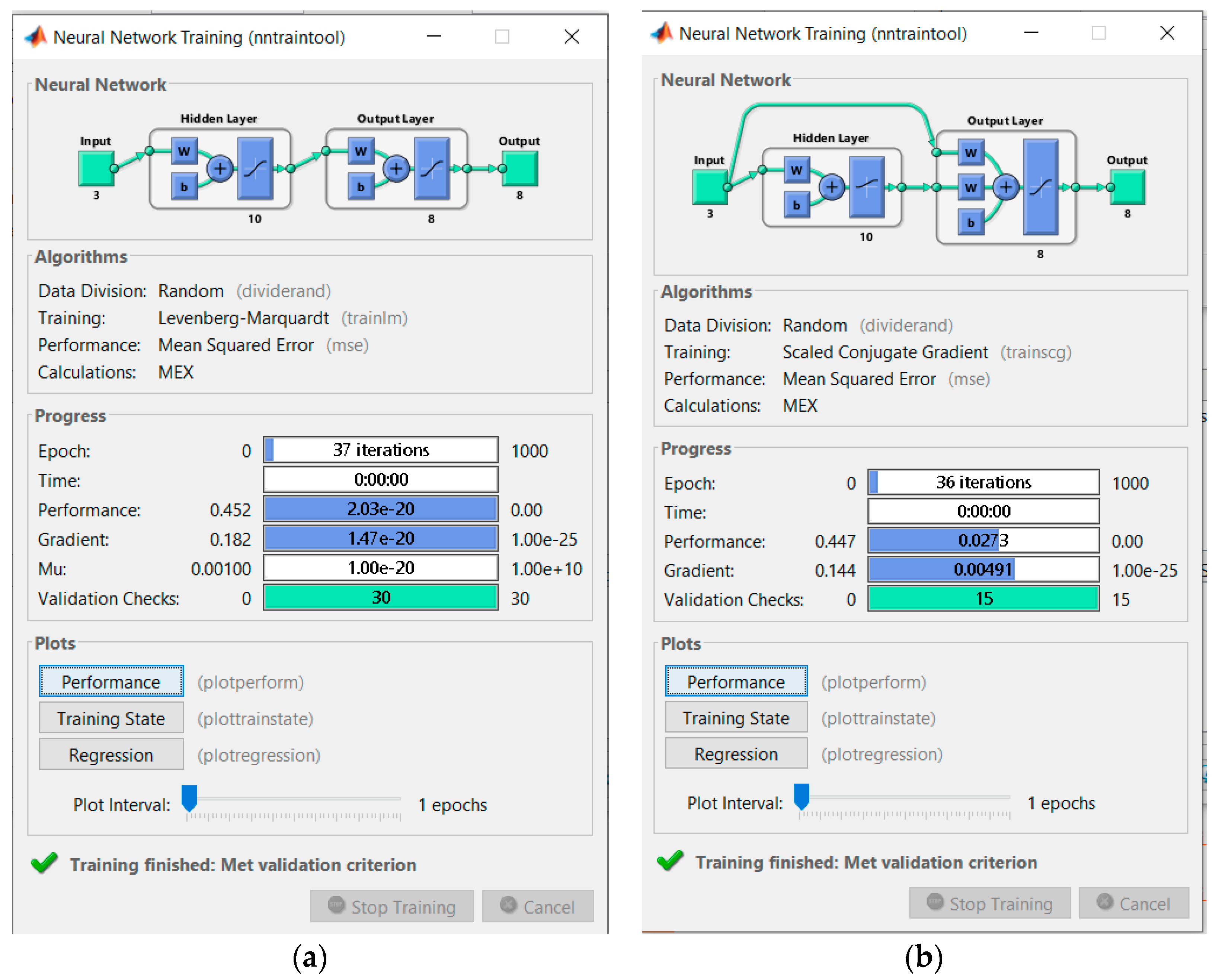
  • Feed-forward back-propagation network. Input patterns are sequentially introduced to input neurons, the ANN response is computed, and the difference (an error) between the output and the response from the training set is evaluated. The error propagates back to the input and changes the settings of neurons to minimize the error.
When implementing the network, we used TRAINLM as a training function, LEARNGND as a learning function, MSE as a performance function, and TANSIG as an activation function. Training details are given in Figure 4a.
  • A cascade-forward back-propagation network is similar to a feed-forward network, but includes connections from the input and every previous layer to the following layers. The network accommodates the nonlinear relationship between the input and the output but does not eliminate the linear relationship in between.
When implementing the network, we used TRAINSCG as a training function, LEARNGND as a learning function, MSE as a performance function, and LOGSIG as an activation function. Training details are given in Figure 4b.
  • A probabilistic network contains radial neurons with a Gaussian activation function in the hidden layer. The output layer sums contributions for each class of input patterns, producing a vector of probabilities as the output. The transfer function of the output layer picks the maximum of these probabilities and produces 1 for the corresponding class. For other classes, 0 is produced.
When implementing the network, we used NEWPNN to create and train the ANN.
In order to test the quality of training, four antennas differing from training patterns (Figure 5) were created and analyzed. Corresponding triplets of resonant frequencies were introduced to the inputs, and ANN was asked to classify the optimum layout:
  • Feed-forward ANN succeeded with 61.2%/59.3%/41.2%/61.4%;
  • Cascaded-forward ANN succeeded with 63.2%/52.3%/40.0%/46.0%;
  • The probabilistic ANN failed.
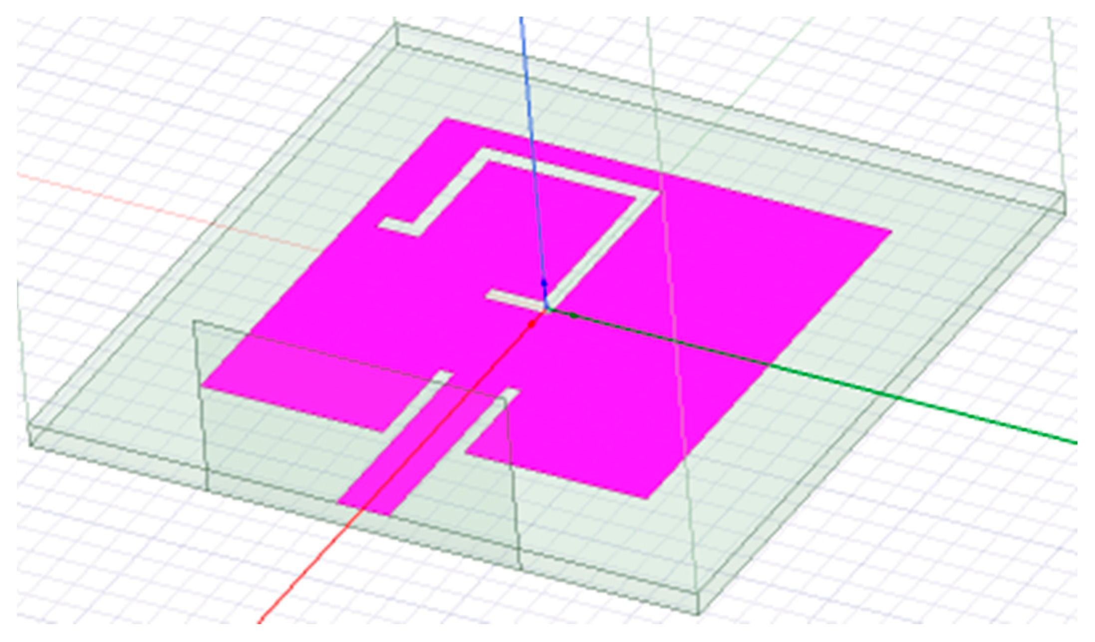
Since the feed-forward back-propagation network showed the best performance, we used this classifier in further tests.

3. Design Example

In order to demonstrate the functionality of the developed methodology, we designed a three-band antenna covering wireless local area network (WLAN) channels:
  • 802.11b/g/n/ax: f1 = 2.4 GHz;
  • 802.11y: f2 = 3.6 GHz;
  • 802.11j: f3 = 4.9 GHz.
The antenna should be designed for the substrate ARLON 25N with εr = 3.38, tan δ = 0.0025, and a height h = 1.524 mm. Since the whole patch is assumed to be in the half-wavelength resonance at f1 = 2.40 GHz, we can evaluate the wavelength in the dielectrics according to [27]:
λ d = c f r ε r
where fr = 2.4 GHz, c is the velocity of light, and the dielectric constant equals to εr = 3.38. Numerically, λd = 68 mm, and the scaling factor related to the neural model equals to n = λd/λ0 = 68/300 = 0.227.
Introducing the triplet of normalized frequencies [2.4/2.4; 3.6/2.4; and 4.9/2.4] to the input of the neural classifier, a G-slot antenna (Figure 2) is recommended as an optimum structure. The size of the patch W × L was 150 mm × 150 mm in the neural model and 34.1 mm × 34.1 mm in the recomputed model.
The coordinates of the vertices A through L of the polygonal slot (Figure 2) produced by the neural classifier are given in Table 1. The dimensions were recomputed using the scale n = 0.227 (Table 1), and a numerical model in HFSS was developed (Figure 6).
In the numerical model, the patch was completed by a microstrip feeder and a wave port (Figure 6). The antenna was simulated in the frequency range of 1.5 GHz–5.0 GHz. The impedance characteristics (Figure 7a) showed that resonance frequencies are shifted.
In a consequent step, Newton optimization was run to shift resonances towards the requested bands. After the optimization, patch dimensions were 30 mm × 30 mm. The vertices of the optimized slot polygon are given in Table 1. The impedance characteristics of the optimized antenna are depicted in Figure 7b. Obviously:
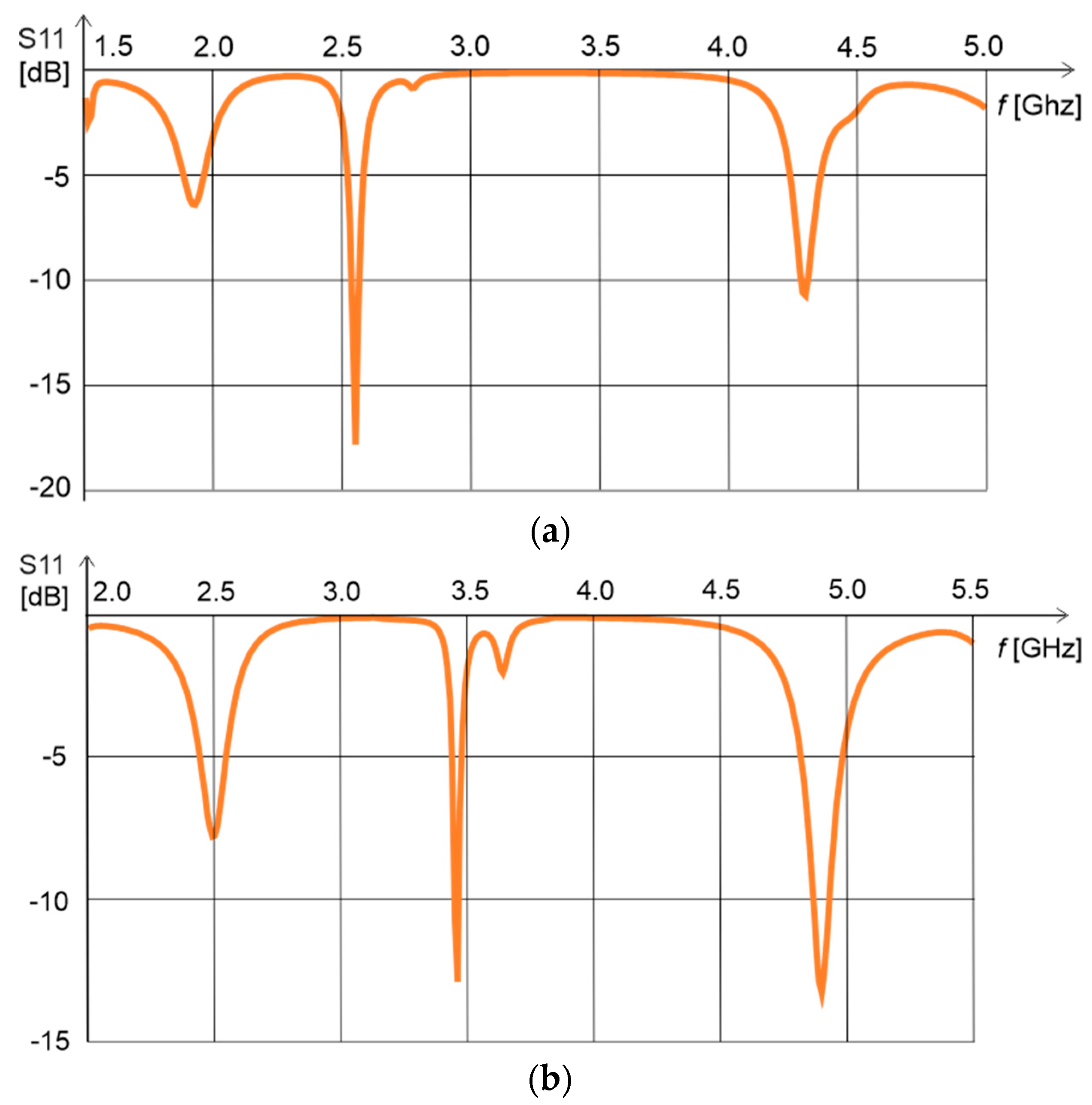
  • f1 = 2.4 GHz is shifted to 2.5 GHz and is not sufficiently deep.
  • f2 = 3.6 GHz corresponds to a shallow minimum, while the deep one is at 3.5 GHz.
  • f3 = 4.9 GHz is tuned successfully with |S11| < −10 dB.

4. Results

In this communication, we trained artificial neural networks on the approximate results of modal analysis. Neural models mapped a triplet of the lowest resonant frequencies to the corresponding layout of a patch. In order to develop sufficiently general neural models, antena structures were normalized. In total, 60 training patterns were created using 9 antenna layouts.
In MATLAB’s Deep Learning Toolbox, we created a feed-forward ANN, a cascaded-forward ANN, and a probabilistic ANN. On four antenna layouts, which were not included in the training sets, the functionality of neural classifiers was tested. Whereas the probabilistic ANN failed, the feed-forward ANN showed relatively good results.
Using the feed-forward ANN, we tried to design a triple-band antenna covering WLAN bands 2.4 GHz, 3.6 GHz, and 4.9 GHz. The neural model returned a G-slot antenna as an optimum structure. The normalized antenna was recomputed for the substrate ARLON 25N, and a corresponding HFSS model was developed. Due to the shift of resonant frequencies with respect to the requested ones, the antenna was optimized by the Newton algorithm.
The optimized impedance characteristics are close to the requested ones, but the match is not perfect. Obviously, the concept of multiband antenna predesign by neural classifiers can work, but much more effort has to be devoted to the composition of a larger and more general training set comprising further families of antenna layouts. If sufficiently large training sets are composed, advanced deep-learning techniques can be applied. This is an intention for future work.

Author Contributions

Conceptualization Z.R. and J.V.; methodology Z.R. and J.V.; validation M.A.L.; investigation, Z.R., M.A.L. and J.V.; writing—original draft preparation Z.R.; writing—review and editing J.O.; visualization Z.R.; supervision Z.R. and J.V.; project administration Z.R. and J.O.; funding acquisition J.O. All authors have read and agreed to the published version of the manuscript.

Funding

The presented research was supported by the Czech Ministry of Defense (AIROPS, the University of Defense development program) and by the Internal Grant Agency of Brno University of Technology (FEKT-S-20-6526).

Conflicts of Interest

The authors declare no conflict of interest.

Abbreviations

ANNArtificial Neural Network
CPUComputer Processing Unit
CPWCoplanar Waveguide
HFSSHigh Frequency Field Simulator
PDEPartial Differential Equation
WLANWireless Local Area Network

References

  1. Balanis, C.A. Antenna Theory: Analysis and Design, 4th ed.; John Wiley & Sons: Hoboken, NJ, USA, 2016; ISBN 978-1-1186-4206-1. [Google Scholar]
  2. Haykin, S. Neural Networks and Learning Machines: A Comprehensive Foundation, 3rd ed.; Pearson Education: Upper Saddle River, NJ, USA, 2009; ISBN 978-0-1314-7139-9. [Google Scholar]
  3. Elshamy, M.M.; Tiraturyan, A.N.; Uglova, E.V.; Elgendy, M.Z. Comparison of feed-forward, cascade-forward, and Elman algorithms models for determination of the elastic modulus of pavement layers. In Proceedings of the 4th International Conference on Geoinformatics and Data Analysis, Marseille, France, 14–16 April 2021. [Google Scholar] [CrossRef]
  4. Raida, Z. Physical layer authentication of off-body channels by probabilistic neural networks. Int. J. Numer. Model. Electron. Netw. Devices Fields 2019, 32, e2628. [Google Scholar] [CrossRef]
  5. Zhang, B.; Jin, C.; Cao, K.; Lv, Q.; Mittra, R. Cognitive conformal antenna array exploiting deep reinforcement learning method. IEEE Trans. Antennas Propag. 2022, 70, 5094–5104. [Google Scholar] [CrossRef]
  6. Zhang, B.; Jin, C.; Cao, K.; Lv, Q.; Zhang, P.; Li, Y.; Li, M. Ultra-wide-scanning conformal heterogeneous phased array antenna based on deep deterministic policy gradient algorithm. IEEE Trans. Antennas Propag. 2022, 70, 5066–5077. [Google Scholar] [CrossRef]
  7. Raida, Z. Modeling EM structures in the neural network toolbox of MATLAB. IEEE Antennas Propag. Mag. 2002, 44, 46–67. [Google Scholar] [CrossRef]
  8. Pal, D.; Singhal, R.; Bandyopadhyay, A.K. Parametric optimization of complementary split-ring resonator dimensions for planar antenna size miniaturization. Wirel. Pers. Commun. 2022, 123, 1897–1911. [Google Scholar] [CrossRef]
  9. Koziel, S.; Çalık, N.; Mahouti, P.; Belen, M.A. Accurate modeling of antenna structures by means of domain confinement and pyramidal deep neural networks. IEEE Trans. Antennas Propag. 2022, 70, 2174–2188. [Google Scholar] [CrossRef]
  10. Zhou, Y.; Xie, J.; Ren, Q.; Zhang, H.H.; Liu, Q.H. Fast multi-physics simulation of microwave filters via deep hybrid neural network. IEEE Trans. Antennas Propag. 2022, 70, 5165–5178. [Google Scholar] [CrossRef]
  11. Faustino, E.; Melo, M.C.; Buarque, P.; Bastos-Filho, C.J.A.; Arismar Cerqueira, S.; Barboza, E.A. Comparison of machine learning algorithms for application in antenna design. In Proceedings of the SBMO/IEEE MTT-S International Microwave and Optoelectronics Conference, Fortaleza, Brazil, 24–27 October 2021. [Google Scholar] [CrossRef]
  12. Karahan, E.A.; Gupta, A.; Khankhoje, U.K.; Sengupta, K. Deep learning based modeling and inverse design for arbitrary planar antenna structures at RF and millimeter-wave. In Proceedings of the 2022 IEEE International Symposium on Antennas and Propagation and USNC-URSI Radio Science Meeting, Denver, CO, USA, 10–15 July 2022. [Google Scholar] [CrossRef]
  13. Mir, F.; Kouhalvandi, L.; Matekovits, L. Deep neural learning based optimization for automated high performance antenna designs. Sci. Rep. 2022, 12, 16801. [Google Scholar] [CrossRef] [PubMed]
  14. Nan, J.; Xie, H.; Gao, M.; Song, Y.; Yang, W. Design of UWB antenna based on improved deep belief network and extreme learning machine surrogate models. IEEE Access 2021, 9, 126541–126549. [Google Scholar] [CrossRef]
  15. Johnson, J.M.; Rahmat-Samii, Y. Genetic algorithms in engineering electromagnetics. IEEE Antennas Propag. Mag. 1997, 39, 7–25. [Google Scholar] [CrossRef] [Green Version]
  16. Weile, D.S.; Michielssen, E. Genetic algorithm optimization applied to electromagnetics: A review. IEEE Trans. Antennas Propag. 1997, 45, 343–353. [Google Scholar] [CrossRef]
  17. Robinson, J.; Rahmat-Samii, Y. Particle swarm optimization in electromagnetics. IEEE Trans. Antennas Propag. 2004, 52, 397–407. [Google Scholar] [CrossRef]
  18. Lu, J.; Ireland, D.; Lewis, A. Multi-objective optimization in high frequency electromagnetics—An effective technique for smart mobile terminal antenna (SMTA) design. IEEE Trans. Magn. 2009, 45, 1072–1075. [Google Scholar] [CrossRef] [Green Version]
  19. Shi, D.; Lian, C.; Cui, K.; Chen, Y.; Liu, X. An intelligent antenna synthesis method based on machine learning. IEEE Trans. Antennas Propag. 2022, 70, 4965–4976. [Google Scholar] [CrossRef]
  20. Vesely, J.; Olivova, J.; Gotthans, J.; Gotthans, T.; Raida, Z. Classification of microwave planar filters by deep learning. Radioengineering 2022, 31, 69–76. [Google Scholar] [CrossRef]
  21. Cap, A.; Raida, Z.; Heras-Palmero, E.; Lamadrid-Ruiz, R. Multi-band planar antennas: A comparative study. Radioengineering 2005, 14, 11–20. [Google Scholar]
  22. Chi, Y.J.; Chen, F.C. On-body adhesive-bandage-like antenna for wireless medical telemetry service. IEEE Trans. Antennas Propag. 2014, 62, 2472–2480. [Google Scholar] [CrossRef]
  23. Ali, T.; Bhudevi, H.; Subhash, B.K.; Prasad, K.D.; Biradar, R.C. A miniaturized dual band antenna loaded with L and G-shaped slots for WiMAX/WLAN applications. In Proceedings of the 3rd IEEE International Conference on Recent Trends in Electronics, Information & Communication Technology (RTEICT), Bangalore, India, 18–19 May 2018. [Google Scholar] [CrossRef]
  24. Hamd, H.I.; Mohamed, W.Q.; Ahmed, H.B. Design and simulation of H shape and duplicate U shape slots microstrip patch antenna for WiMAX applications. In Proceedings of the 5th International Symposium on Multidisciplinary Studies and Innovative Technologies (ISMSIT), Ankara, Turkey, 21–23 October 2021. [Google Scholar] [CrossRef]
  25. Lacik, J.; Mikulasek, T.; Raida, Z.; Urbanec, T. Substrate integrated waveguide monopolar ring-slot antenna. Microw. Opt. Technol. Lett. 2014, 56, 1865–1869. [Google Scholar] [CrossRef]
  26. Partial Differential Equation Toolbox. Available online: https://uk.mathworks.com/products/pde.html (accessed on 28 November 2022).
  27. Garg, R.; Bhartia, P.; Bahl, I.; Ittipiboon, A. Microstrip Antenna Design Handbook; Artech House: Norwood, MA, USA, 2001; ISBN 978-0-8900-6513-6. [Google Scholar]
  28. Deep Learning Toolbox. Available online: https://uk.mathworks.com/help/deeplearning (accessed on 28 November 2022).
Figure 1. Training geometries of normalized multi-band patches: (a) conventional patch, (b) extended patch, (c) L-slot patch, (d) U-slot patch, (e) T-slot patch, (f) double U-slot patch, (g) G-slot patch, (h) H-slot patch, and (i) square-slot patch. Pixel dimensions: 5 mm × 5 mm. Green: conductive surface; white: uncovered substrate.
Electronics 12 01345 g001
Figure 2. Modal analysis of the G-slot patch antenna by the finite-element method in the PDE tool of MATLAB.
Electronics 12 01345 g002
Figure 3. The lowest 3 modes of the G-slot antenna were computed by the finite-element method in the PDE tool in MATLAB.
Electronics 12 01345 g003
Figure 4. Training neural classifiers in the Deep Learning Toolbox of MATLAB: (a) feed-forward back-propagation ANN; (b) cascaded-forward back-propagation ANN.
Electronics 12 01345 g004
Figure 5. Testing the geometries of normalized multi-band patches: (a) triangle-slot patch, (b) circular slot patch, (c) single notch patch, and (d) double notch patch. Pixel dimensions: 5 mm × 5 mm. Green: conductive surface; white: uncovered substrate.
Electronics 12 01345 g005
Figure 6. Numerical model of the G-slot antenna in HFSS. The patch is completed by a microstrip feeder and the wave port.
Electronics 12 01345 g006
Figure 7. Impedance characteristics of the G-slot antenna: (a) initial model, (b) optimized model.
Electronics 12 01345 g007
Table 1. Coordinates of vertices in the polygonal G slot in the patch depicted in Figure 2. Comparison of the neural model, the recomputed one, and the optimized one.
Neural NetworkRecomputedOptimized
A−70.025.0−15.95.7−13.44.7
B−60.025.0−13.65.7−11.64.7
C−60.065.0−13.614.8−11.613.3
D0.065.00.014.80.513.3
E0.00.00.00.00.5−0.5
F−20.00.0−4.50.0−4.0−0.5
G−20.05.0−4.51.1−4.00.6
H−5.05.0−1.11.1−0.60.6
I−5.060.0−1.113.6−0.612.1
J−55.060.0−12.513.6−10.512.1
K−55.020.0−12.54.5−10.53.5
L−70.020.0−15.94.5−13.43.5
Disclaimer/Publisher’s Note: The statements, opinions and data contained in all publications are solely those of the individual author(s) and contributor(s) and not of MDPI and/or the editor(s). MDPI and/or the editor(s) disclaim responsibility for any injury to people or property resulting from any ideas, methods, instructions or products referred to in the content.

