Article

Extended State Observer-Based Predictive Current Control for Dual Three-Phase PMSM with High Dynamic Performance

Research Institute of Intelligent Control and Systems, Harbin Institute of Technology, Harbin 150001, China
*
Author to whom correspondence should be addressed.
Electronics 2023, 12(20), 4266; https://doi.org/10.3390/electronics12204266
Submission received: 22 September 2023 / Revised: 7 October 2023 / Accepted: 13 October 2023 / Published: 15 October 2023

Abstract

:
Model predictive controllers are widely discussed in the field of dual three-phase permanent magnet synchronous motor control. However, conventional predictive current controllers usually suffer from parameter inaccuracies or model uncertainties, resulting in prediction errors and deterioration of control performance. Therefore, in this paper, an extended state observer-based (ESO) model predictive current controller is proposed to effectively improve the dynamic performance of the motor and its robustness to parameters or disturbances. Parameter inaccuracies or model uncertainties are considered to be lumped disturbances and expressed in the modified mathematical model of the motor. Then, with the designed observer estimating the external disturbances in real time, the prediction error is compensated and corrected periodically. Additionally, the parameter design method of the observer is presented to simplify the controller design. Finally, comparative experiments are implemented to sufficiently demonstrate the effectiveness of the proposed method for dynamic performance improvement as well as for parameter robustness. The results show that the proposed method takes only 17 μ s of computation time with a closed-loop bandwidth of 1839 rad / s . In addition, the maximum d-axis following error of the proposed method is only 0.10 A in the load dynamics experiments, which is a significant improvement compared to the 0.79 A of the traditional proportional-integral controller.

1. Introduction

The dual three-phase permanent magnet synchronous motor (DTP-PMSM) has received significant attention from researchers in recent years due to the fault-tolerant performance of its extra winding [1,2,3,4]. Additionally, the requirement for inverter capacity is halved since the additional set of winding shares the phase currents of the motor at the same torque. As a result, DTP-PMSMs are widely used in the fields of ship propulsion, electric vehicles, and other high-power applications [5,6,7].
Traditional control methods based on field-oriented control have been widely applied to three-phase motors, which effectively simplifies the motor control [8]. However, the method cannot be directly applied to DTP-PMSM due to the presence of greater degrees of freedom. Therefore, the vector space decoupling (VSD) based theoretical method is proposed to be applied to the torque control of multiphase motors [9]. The method transforms the six-phase current or voltage components into the electromechanical energy conversion subspace and the harmonic component subspace, respectively. The electromechanical energy subspace is used to control the output torque, while the harmonic component subspace is used to control the current harmonic components of the motor. Thereafter, four conventional proportional-integral (PI) controllers are utilized to control these two subspaces, which enable effective control of both the torque and harmonic components of the DTP-PMSM. Nevertheless, subject to the bandwidth performance of the PI controllers, it is challenging to further improve the dynamic performance for high-performance servo control applications.
Among several existing techniques, the model predictive current controller (MPCC) is a satisfactory and easy-to-implement high-performance solution [10,11,12]. At each control period, MPCC predicts the current using the mathematical model of the motor in order to calculate the optimal control result; thus, the dynamic performance of the current is significantly improved. The existing literature generally categorizes MPCC as finite control set MPCC (FCS-MPCC) and continuous control set MPCC (CCS-MPCC) [13]. The FCS-MPCC searches all available voltage vectors in the inverter and selects the optimal one to apply directly to the motor, therefore providing an adequately high bandwidth. In [14], the authors introduced the concept of virtual vectors to realize robust FCS-MPCC. Additionally, literature [15] presents a space vector-optimized predictive controller to deal with fast current response by presynthesizing space vectors, which improves the dynamic response performance. However, the existing FCS-MPCC needs to search a large number of available vectors, especially when dealing with multi-step prediction. Therefore, such methods usually require a great computational effort for DTP-PMSM [16].
As another class of MPCC methods, CCS-MPCC computes the optimal voltage vector in the whole vector plane directly, avoiding the searching process and thus providing better computational efficiency [17]. In [18], the authors implemented a generalized CCS-MPCC to efficiently increase the torque density. In [19], the scheme of open-switch fault is analyzed in detail, and a high control bandwidth CCS-MPCC under the fault-tolerant operation is proposed. Despite the promising results, conventional MPCC inevitably suffers from prediction errors caused by parameter uncertainties or model nonlinearities such as dead time, resulting in deteriorating performance [20]. To address this problem, researchers have studied a number of possible approaches [21,22,23,24]. In [21], a sliding mode observer (SMO) based MPCC is proposed to eliminate the effects of motor parameters and unmodeled dynamics. Further, one study [22] couples an SMO with a generalized proportional-integral observer for fast-tracking of time-varying disturbances. This class of SMO-based methods has a fast disturbance tracking rate, but the chattering problem is difficult to completely eliminate. Another idea to address the prediction errors introduced by disturbances is to utilize model-free based methods [23,24]. This approach completely eliminates the dependence on motor parameters by using a generalized estimation method instead of using a motor model. Furthermore, in order to compensate for external disturbances, another study [25] suggests the use of extended state observer (ESO) for the estimation of lumped disturbances. Although the robustness of MPCC is enhanced, the dynamic performance of the motor is limited due to the lack of the model.
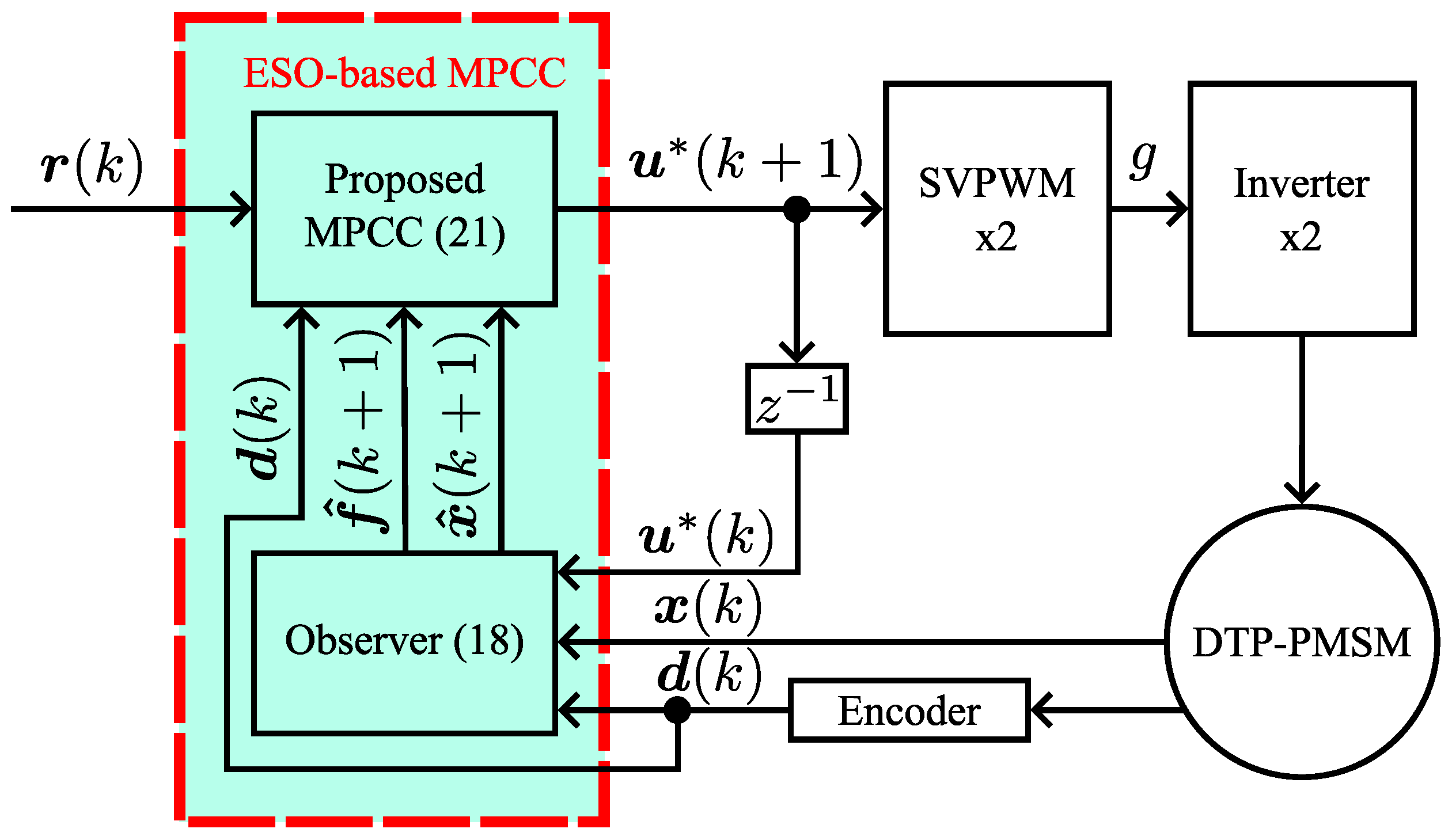
In this paper, an ESO-based robust CCS-MPCC is proposed to enhance the dynamic performance and parameter robustness of DTP-PMSM drives. The external disturbances caused by parameter uncertainties or model nonlinearities are considered as lumped disturbances, which are uniformly estimated by ESO and compensated cycle-by-cycle into MPCC, which effectively enhances the anti-disturbance performance of MPCC. The main contributions of this paper are as follows:
(1)
The conventional DTP-PMSM mathematical model is modified to a form with disturbance term, and an observer is designed for cycle-by-cycle estimation to enhance the disturbance immunity of the controller.
(2)
An observer-based MPCC is constructed where the prediction error of the controller is corrected and compensated by the observer in real time. Additionally, the parameter design method of the observer is given to simplify the design.
(3)
By solving the predictive controller explicitly in the forward direction instead of iteratively, the computational resource consumption is not increased significantly considering the extra subspace of the multi-phase motor.
The rest of the paper is organized by the following structure. The mathematical model construction of DTP-PMSM is given in Section 2. The design procedure, as well as the principle of MPCC, is shown in Section 3. The observer compensation based MPCC, as well as the parameter design of the observer, is presented in Section 4. Comparative experimental results are available in Section 5. The discussion and conclusion are given in Section 6.

2. Mathematical Modeling of the Dual Three-Phase Motor

The mathematical electrical model of dual three-phase motor in the natural coordinate system is:
u 6 s = R 6 s i 6 s + d Φ 6 s d t
where u 6 s is the motor stator voltage vector, R 6 s is denoted as the stator resistance diagonal matrix, i 6 s represents the stator current vector and Φ 6 s means the stator magnetic flux vector. It is quite challenging to control the motor directly using model (1). Therefore, the VSD control strategy is employed in this paper, which significantly simplifies the difficulty of control. The VSD-based rotation matrix T VSD is represented by:
T VSD = 1 3 1 1 / 2 1 / 2 3 / 2 3 / 2 0 0 3 / 2 3 / 2 1 / 2 1 / 2 1 1 1 / 2 1 / 2 3 / 2 3 / 2 0 0 3 / 2 3 / 2 1 / 2 1 / 2 1
The mathematical model of the motor is decomposed to α - β subspace and x-y subspace by applying the rotation matrix T VSD to model (1). The α - β subspace is used to control the electromechanical energy conversion, while the x-y subspace is used to control the harmonic components of the motor. Further, the α - β subspace is transformed to the d-q subspace via the Park transformation, which enables the control of the alternating current to direct current. As a result, the mathematical model of the motor is expressed as:
u d ( t ) = R s i d ( t ) + L d d i d ( t ) d t ω e ( t ) L q i q ( t ) u q ( t ) = R s i q ( t ) + L q d i q ( t ) d t + ω e ( t ) L d i d ( t ) + ω e ( t ) ϕ f u x ( t ) = R s i x ( t ) + L x y d i x ( t ) d t u y ( t ) = R s i y ( t ) + L x y d i y ( t ) d t
where u d , u q , u x and u y are denoted as voltages under the d-, q-, x- and y-axis, respectively, which are utilized to control the behavior of the motor [ V ]; i d , i q , i x and i y are the currents under the d-, q-, x- and y-axis, respectively [ A ]; R s is denoted as the stator resistance [ Ω ]; L d and L q are the direct and quadrature axis inductances [ H ]; L x y is the leakage inductance [ H ]; ω e is the motor electrical speed [ rad / s ] and ϕ f is the magnetic flux of permanent magnets [ Wb ].
Expressing model (2) as the state space expression, one can obtain the mathematical control model as follows:
x ˙ ( t ) = A c x ( t ) + B u c u ( t ) + B d c d ( t ) y ( t ) = C c x ( t )
where x = [ i d , i q , i x , i y ] T is the state variable; u = [ u d , u q , u x , u y ] T is the control effort; d = ω e is the measurable disturbance and y = [ i d , i q , i x , i y ] T is the system output. A c and B u c are given by (4); B d c = diag [ 0 , ϕ f / L q , 0 , 0 ] T and C c = I is a unit matrix.
A c = R s L d ω e L q L d 0 0 ω e L d L q R s L d 0 0 0 0 R s L x y 0 0 0 0 R s L x y ,   B d c = 1 L d 0 0 0 0 1 L q 0 0 0 0 1 L x y 0 0 0 0 1 L x y
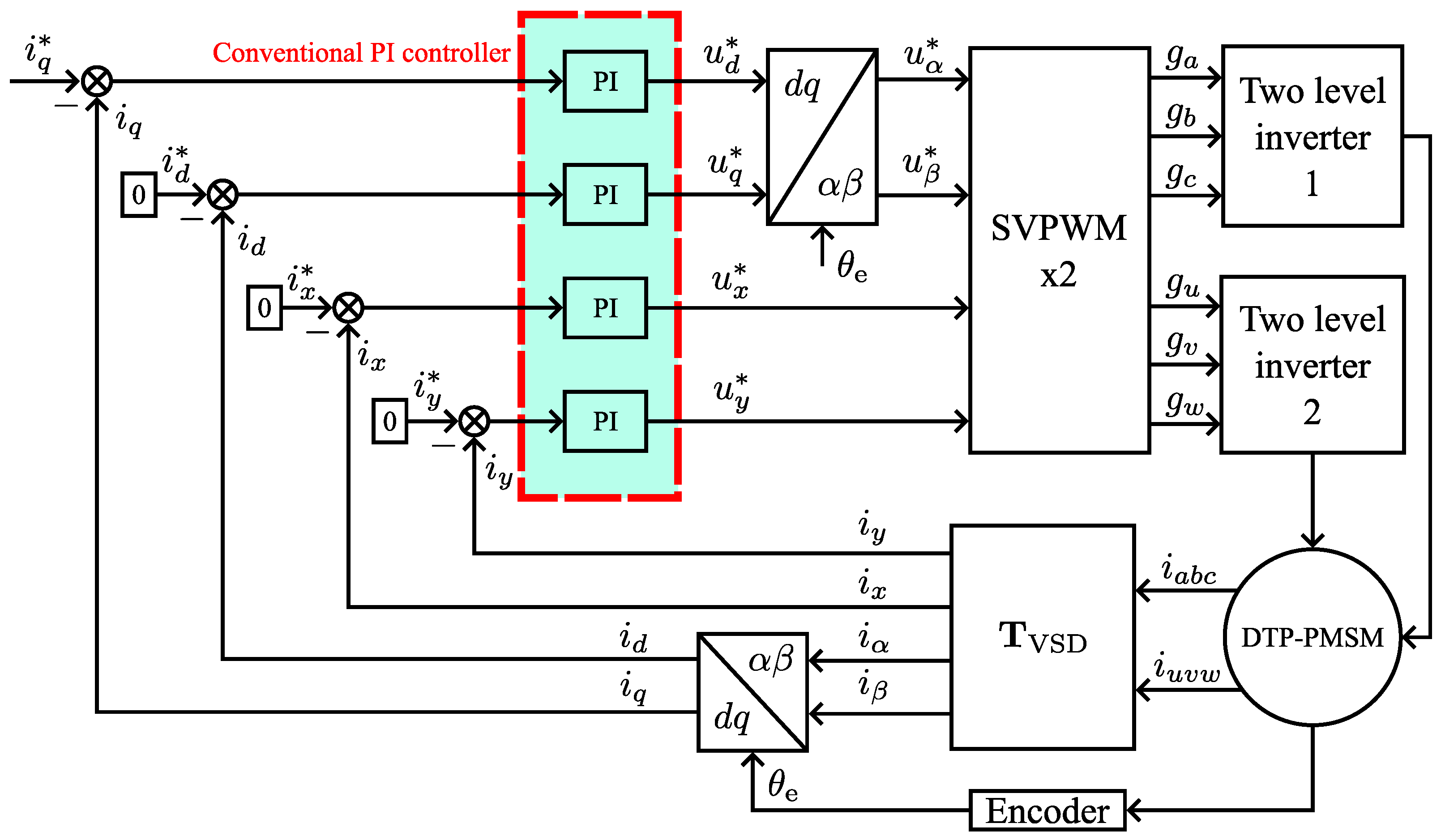
Four conventional PI controllers are then applied to control the four current components in x , thereby realizing the decoupled control of the dual three-phase motor. Therefore, the brief principle of conventional motor control is shown in Figure 1.

3. Design of Model Predictive Current Controller

After discretizing model (3) with the first-order Euler discretization method, the prediction model used for the controller is obtained as:
x ( k + 1 ) = A x ( k ) + B u u ( k ) + B d d ( t ) y ( k ) = C x ( k )
where A = T s A c + I , B u = T s B u c , B d = T s B d c , C = C c and T s is sampling period or control period.
In order to achieve the tracking control of the current, the cost function at time step k as shown in Equation (6) is defined.
J ( k ) = i = 1 N p y ( k + i | k ) r ( k ) Γ i 2
where N p is the prediction horizon and r = [ i d , i q , i x , i y ] T is the reference value of current; y ( k + i | k ) represents the output of the system at step k when the system is predicted to step i; Γ i is the weight matrix assigned to the different currents in the tracking control at the step k of the prediction. The goal of tracking control is to control the actual current to be consistent with the reference. Therefore, when J ( k ) in the cost function (6) is smaller, it indicates that the control effort is more effective at the kth step.
Since the electrical constant of the motor is much smaller than the mechanical constant, the measurable disturbance d ( k ) , also referred as the electrical speed, remains constant during the prediction process. Thus, the assumption (7) is satisfied in this paper.
d ( k ) = d ( k + 1 ) = = d ( k + N p )
Bringing model (5) and assumption (7) into y ( k + i | k ) , the output of the system Y p ( k + 1 | k ) = [ y T ( k + 1 | k ) , y T ( k + 2 | k ) , , y T ( k + N u | k ) , , y T ( k + N p | k ) ] T during the prediction process is derived in (8) and N u is the control horizon.
Y p ( k + 1 | k ) = C A C A 2 C A N p S x x ( k ) + C B u 0 0 C A B u C B u 0 C A N p 1 B u C A N p 2 B u i = 0 N p N u C A i B u S u u ( k ) u ( k + 1 ) u ( k + N p 1 ) U ( k ) + C B d C A B d + C B d i = 0 N u 1 C A i B d S d d ( k ) = S x x ( k ) + S u U ( k ) + S d d ( k )
The cost function can be further expanded as follows:
J ( k ) = i = 1 N p y ( k + i | k ) r ( k ) Γ i 2 = ( Y p ( k + 1 | k ) I r r ( k ) ) T diag ( Γ 1 , Γ 2 , , Γ N p ) Γ ( Y p ( k + 1 | k ) I r r ( k ) ) = ( Y p ( k + 1 | k ) I r r ( k ) ) T ( Γ ) T Γ ( Y p ( k + 1 | k ) I r r ( k ) ) = ( Γ Y p ( k + 1 | k ) Γ I r r ( k ) ) T ( Γ Y p ( k + 1 | k ) Γ I r r ( k ) )
where I r = [ I , I , , I ] T and Γ i denotes the diagonal matrix of weighting coefficients assigned to the different current components in the tracking control at prediction step i. Substituting (8) into (9), J ( k ) is simplified to:
J ( k ) = ( M X N ) T ( M X N )
and:
M = Γ S u , X = U ( k ) , N = Γ ( I r r ( k ) S x x ( k ) S d d ( k ) )
By taking the partial derivative of (10) and making it zero, the optimal control effort U ( k ) at step k is found.
J ( k ) X = 0 X = U ( k ) = ( M T M ) 1 M T N
Considering that only the first step control effort is applied, the control output at step k is:
u ( k ) = [ I , 0 , , 0 ] U ( k ) = [ I , 0 , , 0 ] ( S u T ( Γ ) T Γ S u ) 1 S u T ( Γ ) T Γ K mpc ( I r r ( k ) S x x ( k ) S d d ( k ) ) = K mpc ( I r r ( k ) S x x ( k ) S d d ( k ) )
Consequently, the controller (13) is the ideal model predictive current controller, and the optimal control output is applied to the inverter at each control cycle.

4. Proposed Observer-Based Robust MPCC Method

Due to unavoidable parameter uncertainties or model nonlinearities such as inverter dead-time, the prediction error occurs when model (3) is used to predict the current, resulting in deterioration of the control performance. Therefore, an observer-based predictive current controller is proposed in this section.

4.1. Observer-Based Predictive Controller Design

The ideal prediction model (3) is adapted to correct the prediction error as shown in model (14). Compared to the existing models, model (14) possesses the capability of disturbance correction, which achieves better accuracy in prediction.
x ˙ ( t ) = A c x ( t ) + B u c u ( t ) + B d c d ( t ) + B f c f ( t ) y ( t ) = C c x ( t )
where B f c = I is a unit matrix; f ( t ) is the external lumped disturbance and requires to be estimated in real time. Taking the motor parameters from Table 1 into the observability matrix of the system, the rank of the matrix is 4 as shown in (15), which is consistent with the system dimension. Therefore, the system is observable.
rank C c C c A c C c A c 2 C c A c 3 = 4 = dimension of the system
The ESO based on model (14) is constructed to estimate f ( t ) cycle-by-cycle as follows:
z ^ ˙ ( t ) = ( A ˜ c L c C ˜ c ) z ^ ( t ) + B ˜ u c u ( t ) + B ˜ d c d ( t ) + L c C c x ( t ) y ^ ( t ) = C ˜ c z ^ ( t )
where z ( t ) = [ x T ( t ) , f T ( t ) ] T and z ^ ( t ) is the estimation of z ( t ) ; A ˜ c , L c , C ˜ c , B ˜ u c and B ˜ d c are given by (17). The design of the observer gain L c will be presented in the following Section 4.2.
A ˜ c = A c B f c 0 0 , L c = L c 1 L c 2 , C ˜ c = C c 0 , B ˜ u c = B u c 0 , B ˜ d c = B d c 0 , L c 1 = diag ( β d , β q , β x , β y ) , L c 2 = diag ( β f d , β f q , β f x , β f y )
By discretizing the observer (16) with first-order Euler discretization, the lumped disturbance estimation f ^ of the model is estimated with (18). The disturbances are used to compensate for model uncertainties or nonlinearities in the prediction process, thus improving the robustness of the controller.
x ^ ( k + 1 ) = ( A T s L c 1 C ) x ^ ( k ) + B f f ^ ( k ) + B u u ( k ) + B d d ( k ) + T s L c 1 C x ( k ) f ^ ( k + 1 ) = T s L c 2 C x ^ ( k ) + f ^ ( k ) + T s L c 2 C x ( k )
When the model (14) is utilized for prediction, the optimal controller in Section 3 can be derived and modified in a similar way, as seen below:
u ( k ) = K mpc ( I r r ( k ) S x x ( k ) S d d ( k ) S f f ( k ) ) , S f = C T s B f c C T s B f c + C T s B f c i = 0 N u 1 C A i T s B f c
Substituting the estimation results of the observer (18) into the predictive controller (19), the ESO-based robust MPCC is designed.
u ( k ) = K mpc ( I r r ( k ) S x x ^ ( k ) S d d ( k ) S f f ^ ( k ) )
Further, when considering one-step delay of the digital system, the current x and the disturbance f require to be predicted one step before being brought into the controller. Therefore, Equation (20) is modified:
u ( k + 1 ) = K mpc ( I r r ( k ) S x x ^ ( k + 1 ) S d d ( k ) S f f ^ ( k + 1 ) )
Finally, the logic schematic of the proposed method is presented in Figure 2. The disturbances are estimated and compensated into the controller in real time, which effectively improves the robustness of the proposed method to parameter inaccuracies as well as the dynamic performance.

4.2. Parameter Design of the Observer

In order to guarantee stability, the eigenvalues of the system matrix A ˜ c L c C ˜ c in the observer (16) should have a negative real part. Therefore, the pole placement method is adopted for designing the parameters of the observer.
s I ( A ˜ c L c C ˜ c ) = ( s + ω ob ) 8
where s is the Laplace operator and ω ob is the desired bandwidth of the observer. Larger bandwidth brings faster observation speeds. However, this is a tradeoff between speed and noise amplification, which introduces instability as well as vibration into the system.
By solving (22), the parameters of the observer are derived as follows:
β d = 2 ω ob R s L d ω e β q = 2 ω ob R s L q + ω e β x = β y = 2 ω ob R s L x y β f d = β f q = β f x = β f y = ω ob 2 or β d = 2 ω ob R s L d + ω e β q = 2 ω ob R s L q ω e β x = β y = 2 ω ob R s L x y β f d = β f q = β f x = β f y = ω ob 2

5. Experimental Results

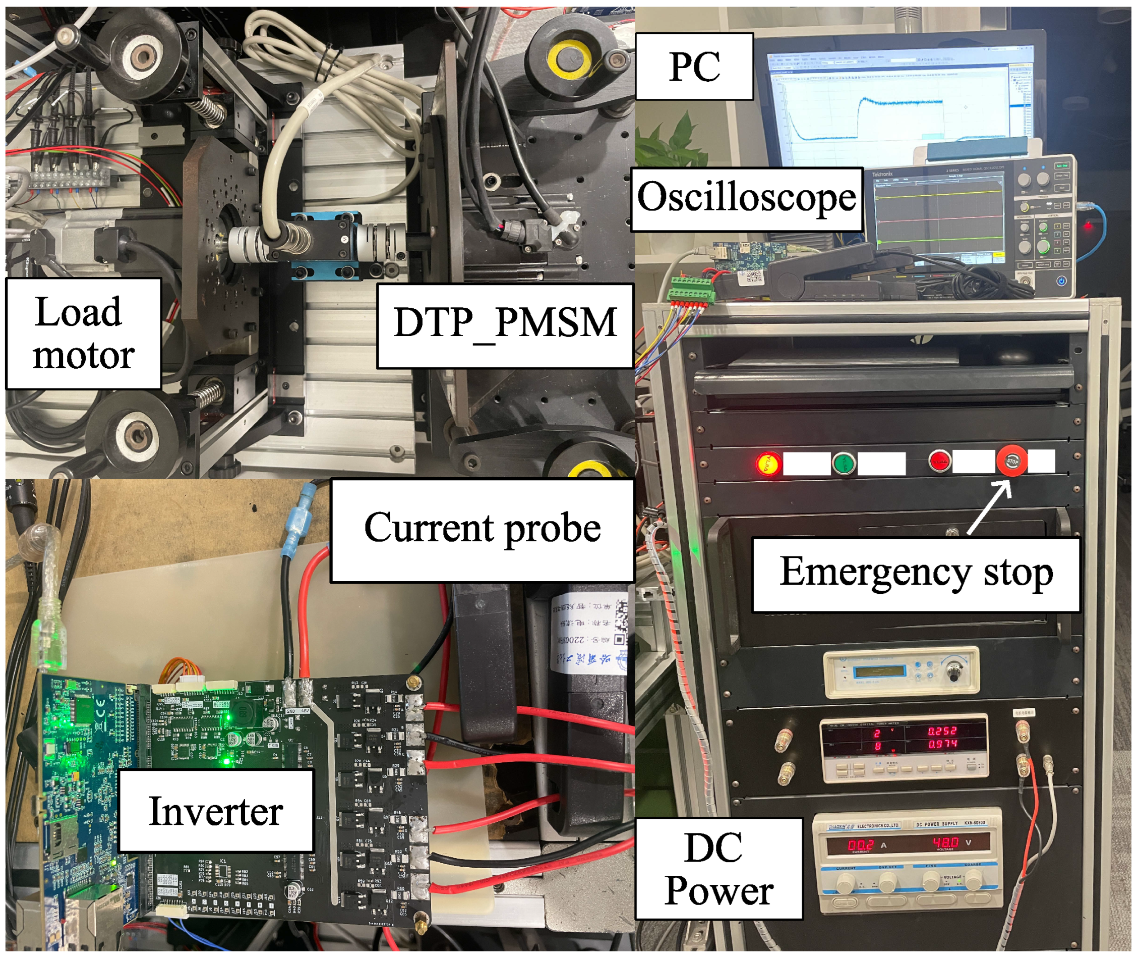
In order to verify the effectiveness of the proposed method, multiple sets of experiments are implemented. In addition, the conventional PI control method is realized for comparison of performance. The controllers are all run in the TMS320F28388D (digital signal processor) manufactured by Texas Instruments. In addition, the DTP-PMSM is mounted on the testbench, and the simulated load is provided by a load motor. The parameters of the DTP-PMSM are listed in Table 1 and the whole experimental platform is shown in Figure 3.
The parameters of the proposed method are listed in Table 2. Considering the computational complexity, N p and N u are determined as 2 and 1, respectively, to simplify the computation. At the same time, the desired bandwidth of observer ω ob is selected as 500 Hz to satisfy the fast observation performance without signal noise amplification. In addition, Γ is chosen as a unit matrix due to the same importance of tracking control for different currents. Additionally, the parameters of proportional coefficient K p and integral coefficient K i with conventional PI control are calculated by Equation (24), where ω PI is the desired bandwidth.
K p = ω PI L d ( q ) K i = R s L d ( q )

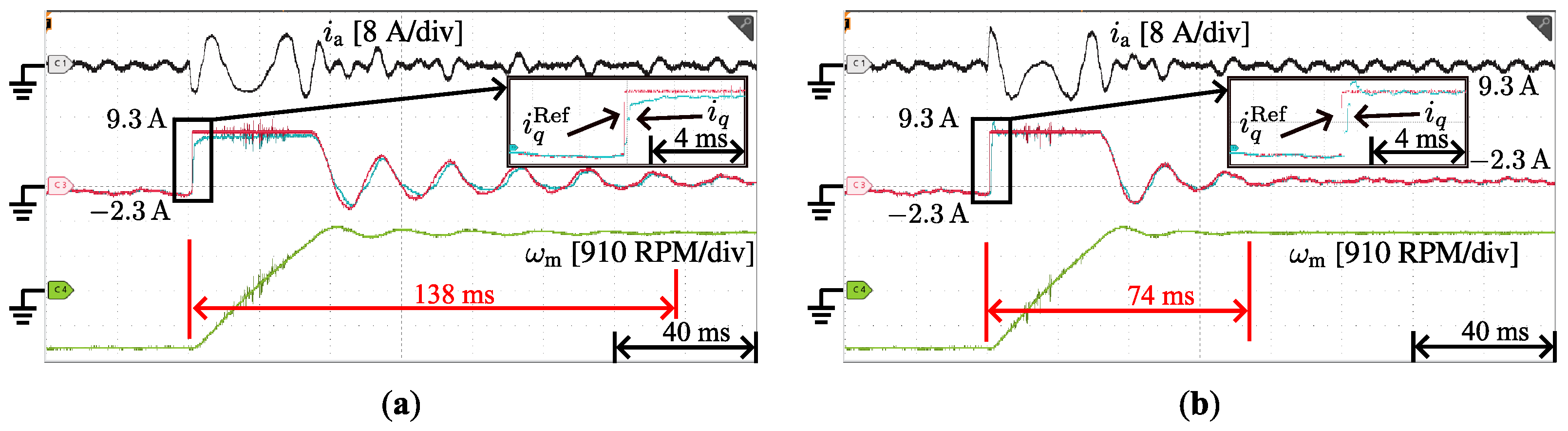
5.1. Dynamic Experimental Results with Speed Reversal

The speed reversal experiments are implemented to verify the dynamic performance of the proposed method during speed variation. The test motor is operated in speed loop, and the speed reference of the motor is changed abruptly from −1500 RPM to 1500 RPM at 40 ms.
Figure 4 presents the experimental results of the a-phase current i a , the reference and actual values of the current in the q-axis, and the mechanical speed ω m when the motor is reversed. The figure shows that the tracking performance of the q-axis current suffers from a large latency and a steady state error when using a conventional PI controller, while the proposed method demonstrates a better satisfactory tracking performance and eliminates the steady state error. In addition, the settling time of the speed is reduced from 138 ms with the PI controller to 74 ms with the proposed method, which further validates the effectiveness of the proposed method.
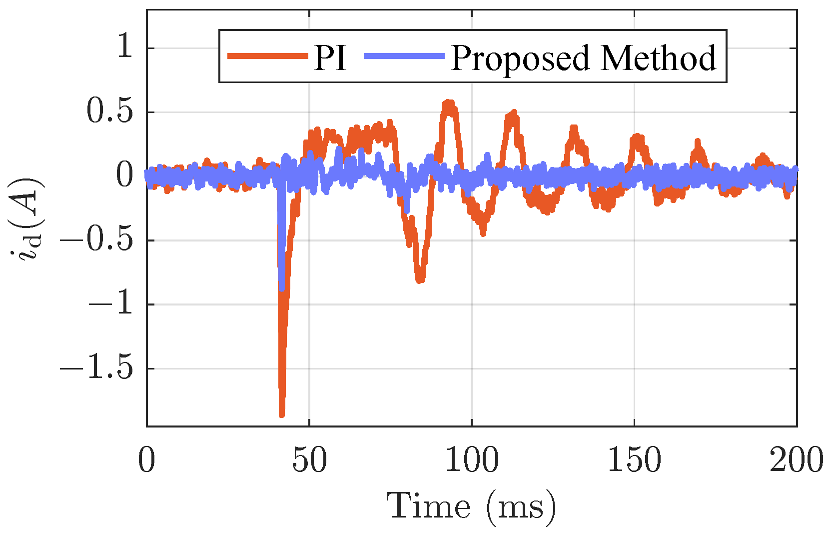
Figure 5 demonstrates the d-axis current tracking results when the speed is reversed. It is clear from the figure that the PI controller has an overshoot of −1.86 A at 40 ms, with a noticeable ripple following. The proposed method has only a current overshoot of −0.88 A, and the steady state ripple is significantly lower than that of the conventional method. Additionally, in order to evaluate the tracking performance of the currents properly, the root-mean-square (RMS) value of the tracking error is employed for the comparison. As shown in 
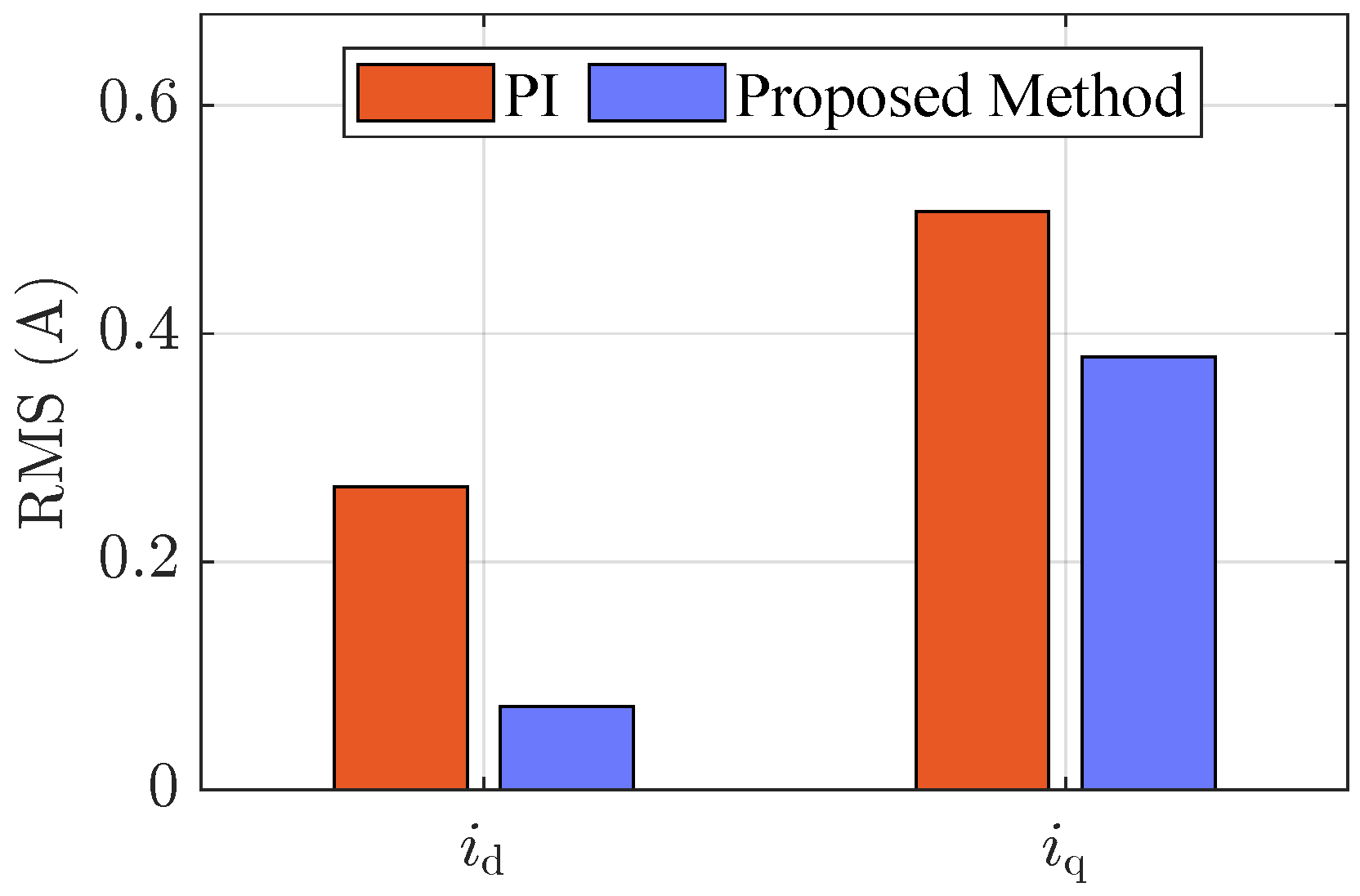
Figure 6, the RMS values of the d-axis and q-axis current following error with the PI controller are 0.26 A and 0.51 A, respectively, while the proposed method has a following error RMS value of 0.07 A and 0.38 A, which is significantly improved over the conventional method.

5.2. Dynamic Experimental Results with Load Disturbance

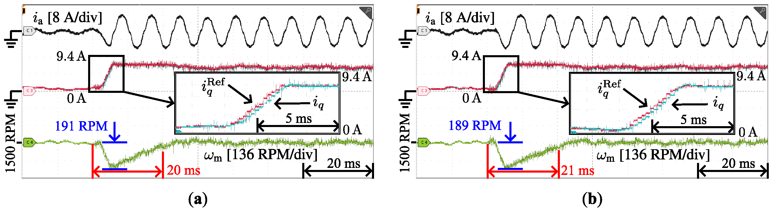
To verify the dynamic performance of the proposed method under load disturbance, the conventional and the proposed method are implemented for comparison. The test motor operates in speed loop mode, and the reference value of speed is set to 1500 RPM, while the load motor operates in current loop mode and is connected to the test motor through mechanical coupling to provide simulated load disturbance. At the time of 20 ms, the torque of the load motor is set to the rated value.
Figure 7 shows the dynamic experimental results of different controllers under load disturbance. The figure shows that the PI controller has a maximum speed drop of 191 RPM with a settling time of 20 ms under load disturbance, while the proposed method has a maximum speed drop of 189 RPM with a settling time of 21 ms, which indicates that the proposed method has similar performance to the conventional controller. However, Figure 8 shows that for the d-axis current tracking performance, the conventional PI controller has a large current overshoot of 0.79 A. The proposed method eliminates this overshoot, and the maximum overshoot is only 0.10 A, which demonstrates that the proposed method can provide satisfactory current tracking performance, especially for the d-axis current during the load vibration.
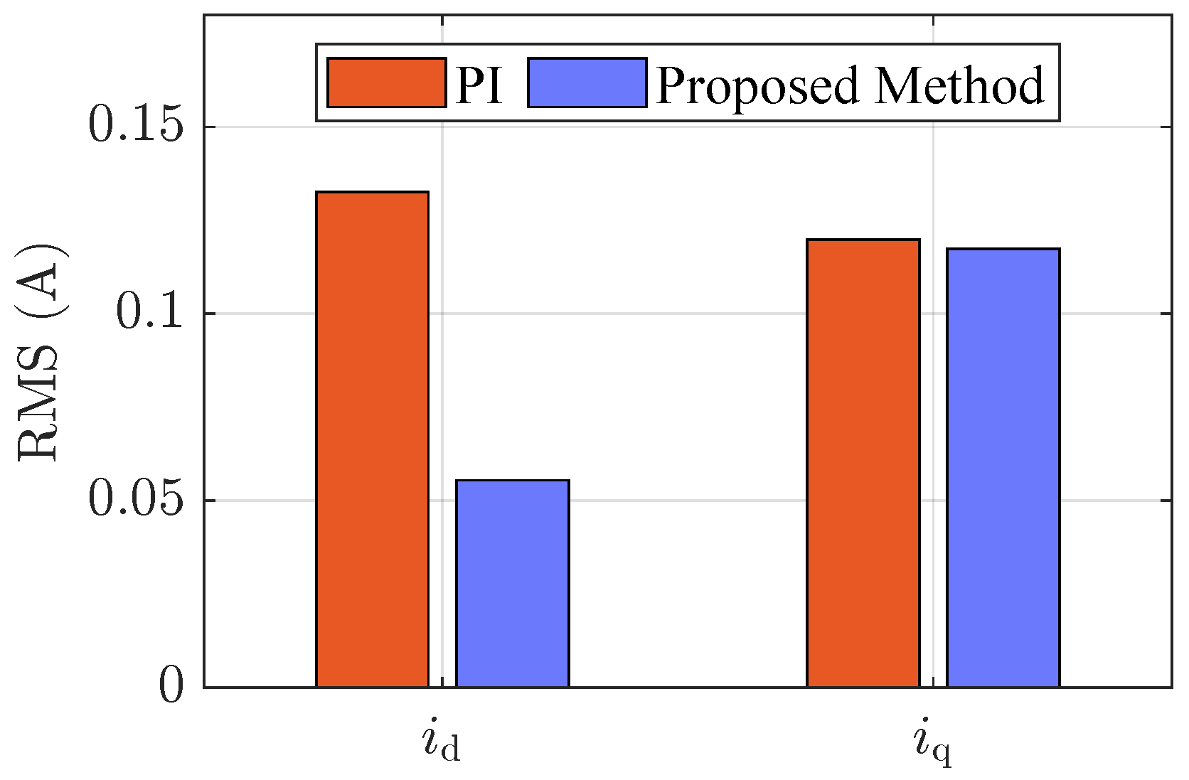
In addition, the RMS results of the d-axis and q-axis current following errors are presented in Figure 9. For the q-axis current, the RMS of the following errors with the conventional method and the proposed method is 0.12 A and 0.12 A, respectively, which are quite similar. Nevertheless, for the following error of the d-axis current, the RMS values are 0.13 A and 0.06 A, respectively. This indicates that the proposed method provides more efficient performance for d-axis current tracking.

5.3. Experimental Results on Parameter Robustness

This set of experiments demonstrates the robust current tracking control performance of the PI controller and proposed method under different motor parameters. The test conditions are the same as in Section 5.1, where the test motor is operated in the speed loop mode, and the speed reference is changed abruptly from −1500 rpm to 1500 RPM.
As can be seen from Table 3, the current following error RMS values of the proposed method under nominal motor parameters are 0.07 A for i d and 0.37 A for i q . As the variation in the motor parameters, the following error RMS values of the d-axis currents remain at 0.06 A to 0.18 A. At the same time, the following error RMS values of the q-axis current present a minor difference with the variation in the parameters. Even the worst case, i.e., at 50% of L d ( L q ) , is still 0.55 A, which is only a slight performance degradation compared to 0.37 A at the nominal parameter. This indicates that the proposed method has satisfactory robust current control performance for motor parameter variations.

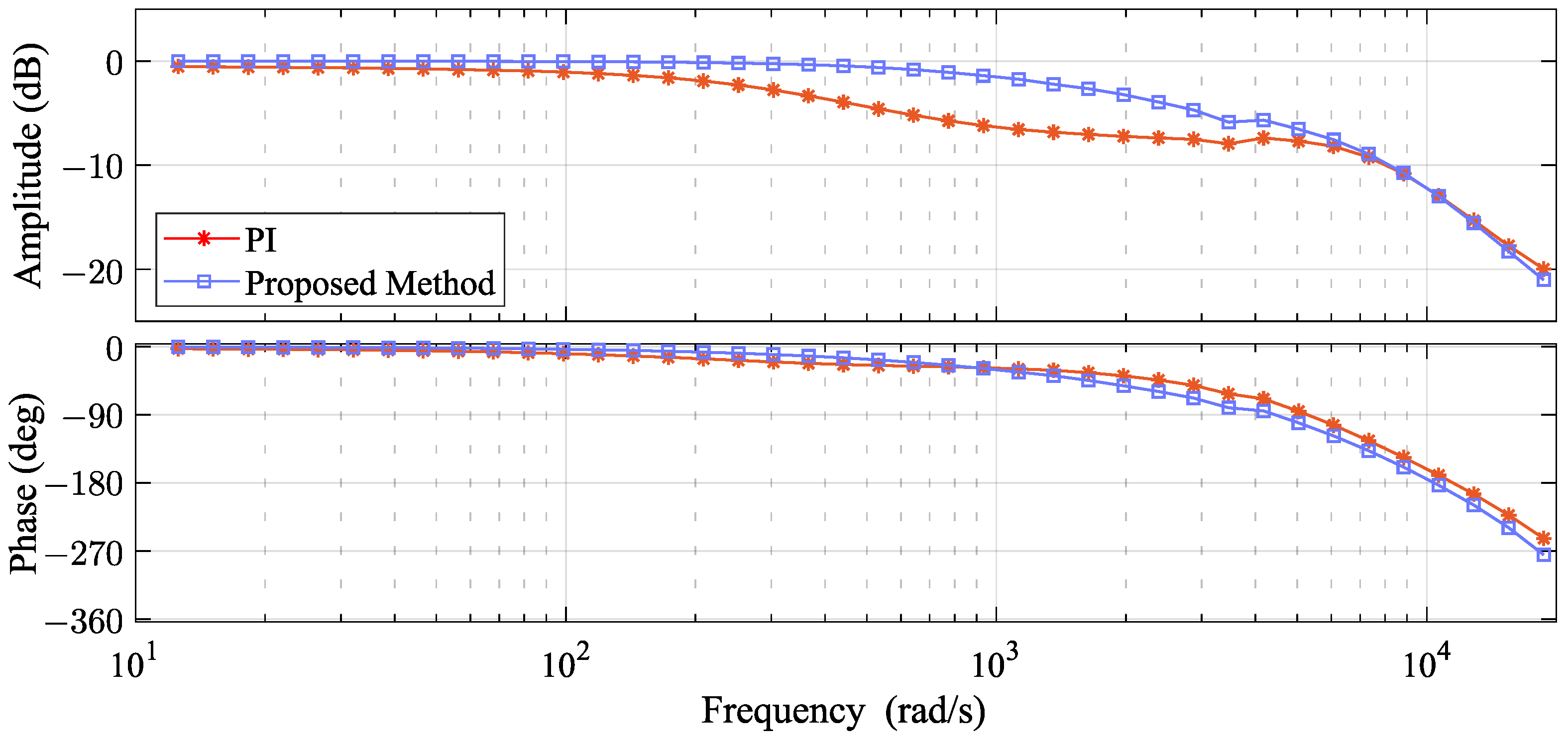
5.4. Experimental Results of Frequency Response

For further investigation into the dynamic performance of the proposed method, frequency response experiments of both PI and the proposed controller are realized. The load motor is removed from the mechanical coupling since free rotation is required for the test motor. Additionally, a sinusoidal signal with an amplitude of 1.85 A and a frequency from 2   Hz to 2975 Hz is injected into the q-axis current of the test motor. By collecting the response results of the current and analyzing them in comparison with the injected signal, one can obtain the closed-loop frequency response plot of the system, as shown in Figure 10. The figure shows that the closed-loop bandwidth of the conventional PI method has only 387 rad / s , while the proposed method increases the bandwidth to 1839 rad / s . Therefore, the proposed method effectively increases the bandwidth of the closed-loop system and offers sufficient current tracking capability.

5.5. Experimental Results on Computational Burden

Predictive controllers are often known for having significant computational burdens; therefore, the computational time consumed by different controllers is evaluated. By toggling the output port before and after the controller operation, the running time of PI and proposed controller are measured by an oscilloscope as shown in Figure 11. The longer the computation time, the more resources the method consumes. From the figure, it is clear that the computational time consumed by the conventional PI controller is 14   μ s while the proposed method consumes 17   μ s , which is not a significant increase in time. This is because the predictive controller used in the proposed method directly computes the optimal control result without iterative solving or searching for all the available voltage vectors.
Regardless of which controller is used, there is sufficient remaining time to execute other control algorithms, such as position loop or vibration suppression, compared to a control cycle of 100   μ s . Therefore, the proposed method provides better control performance without significant consumption of computational resources.

6. Discussion and Conclusions

In this paper, an extended state observer-based model predictive current controller is proposed for DTP-PMSM drives to improve the dynamic performance of the current loop. The mathematical model of the motor is briefly derived and discretized for predicting the current. In addition, the multi-step continuous control set predictive controller is derived and given to obtain an explicit solution for the optimal control voltage, which does not introduce a significant increase in computation time. In order to address the performance deterioration due to prediction errors, a robust observer-based MPCC method is designed for efficient observation of external disturbances, and the parameter design methodology of the observer is also presented. At each control period, external disturbances due to factors such as parameter inaccuracies or nonlinearities in the model are observed. At the same time, the observation results are compensated into the controller in real time after a step of prediction, which is applied to correct the prediction error. Therefore, the proposed method improves the dynamic performance and robustness to external disturbances effectively. Finally, multiple sets of experimental results are demonstrated to indicate the effectiveness of the proposed method.
Since the proposed method is based on a generalized motor model and the external disturbances are uniformly observed without loss of generality, it can be applied to DTP-PMSM at various power levels, including low-power applications, such as robotic arm joint motors or quadruped robots and high-power applications, such as electric vehicles, power trains, and other fields. As the external disturbances are uniformly observed in this study, future work can physically model some of the disturbances to reduce the observation requirements of the observer and further enhance the robust performance of the controller.

Author Contributions

Conceptualization, H.L.; methodology, H.L. and W.L.; software, H.L. and D.L.; validation, H.L. and D.L.; formal analysis, H.L.; investigation, H.L. and D.L.; resources, W.L.; data curation, H.L. and D.L.; writing—original draft preparation, H.L. and D.L.; writing—review and editing, W.L.; visualization, H.L.; supervision, W.L.; project administration, W.L.; funding acquisition, W.L. All authors have read and agreed to the published version of the manuscript.

Funding

This work was supported by the key R&D projects in Sichuan province (No. 2023YFG0061).

Data Availability Statement

Not applicable.

Conflicts of Interest

The authors declare no conflict of interest.

References

  1. Wu, Z.; Cheng, C.; Hua, W.; Zhang, H.; Yin, H.; Hu, M. A Sensorless Control Method Based on High Frequency Injection for Dual Three Phase Motor with Asymmetric Windings. In Proceedings of the 2022 25th International Conference on Electrical Machines and Systems (ICEMS), Chiang Mai, Thailand, 29 November–2 December 2022; pp. 1–6. [Google Scholar] [CrossRef]
  2. Miyama, Y.; Ishizuka, M.; Kometani, H.; Akatsu, K. Vibration Reduction by Applying Carrier Phase-Shift PWM on Dual Three-Phase Winding Permanent Magnet Synchronous Motor. IEEE Trans. Ind. Appl. 2018, 54, 5998–6004. [Google Scholar] [CrossRef]
  3. Yu, K.; Wang, Z. An Online Compensation Method of VSI Nonlinearity for Dual Three-Phase PMSM Drives Using Current Injection. IEEE Trans. Power Electron. 2022, 37, 3769–3774. [Google Scholar] [CrossRef]
  4. Huang, Y.; Walden, J.; Zhang, X.; Yan, Y.; Bai, H.; Jin, F.; Cheng, B. A Novel Zero/Reduced Common-Mode Voltage Modulation Scheme for a Dual Three-Phase Motor Drive System in Full Modulation Span. IEEE Trans. Power Electron. 2022, 37, 6765–6779. [Google Scholar] [CrossRef]
  5. Amin, M.M.; El-Sousy, F.F.M.; Mohammed, O.A.; Aziz, G.A.A.; Gaber, K. MRAS-Based Super-Twisting Sliding-Mode Estimator Combined With Block Control and DTC of Six-Phase Induction Motor for Ship Propulsion Application. IEEE Trans. Ind. Appl. 2021, 57, 6646–6658. [Google Scholar] [CrossRef]
  6. Nair, S.V.; Harikrishnan, P.; Hatua, K. Six-Step Operation of a Symmetric Dual Three-Phase PMSM With Minimal Circulating Currents for Extended Speed Range in Electric Vehicles. IEEE Trans. Ind. Electron. 2022, 69, 7651–7662. [Google Scholar] [CrossRef]
  7. Zhang, Z.; Sun, Q.; Zhang, Q. A Computationally Efficient Model Predictive Control Method for Dual Three-Phase PMSM of Electric Vehicle With Fixed Switching Frequency. IEEE Trans. Ind. Appl. 2023; early access. [Google Scholar] [CrossRef]
  8. Chen, Z.; Shi, T.; Lin, Z.; Wang, Z.; Gu, X. Analysis and Control of Current Harmonic in IPMSM Field-Oriented Control System. IEEE Trans. Power Electron. 2022, 37, 9571–9585. [Google Scholar] [CrossRef]
  9. Zhao, Y.; Lipo, T. Space vector PWM control of dual three-phase induction machine using vector space decomposition. IEEE Trans. Ind. Appl. 1995, 31, 1100–1109. [Google Scholar] [CrossRef]
  10. Carlet, P.G.; Favato, A.; Bolognani, S.; Dörfler, F. Data-Driven Continuous-Set Predictive Current Control for Synchronous Motor Drives. IEEE Trans. Power Electron. 2022, 37, 6637–6646. [Google Scholar] [CrossRef]
  11. Zhang, Y.; Yin, Z.; Li, W.; Liu, J.; Zhang, Y. Adaptive Sliding-Mode-Based Speed Control in Finite Control Set Model Predictive Torque Control for Induction Motors. IEEE Trans. Power Electron. 2021, 36, 8076–8087. [Google Scholar] [CrossRef]
  12. Mousavi, M.S.; Davari, S.A.; Nekoukar, V.; Garcia, C.; Rodriguez, J. Computationally Efficient Model-Free Predictive Control of Zero-Sequence Current in Dual Inverter Fed Induction Motor. IEEE J. Emerg. Sel. Top. Power Electron. 2023, 11, 1332–1344. [Google Scholar] [CrossRef]
  13. Jiang, X.; Yang, Y.; Fan, M.; Ji, A.; Xiao, Y.; Zhang, X.; Zhang, W.; Garcia, C.; Vazquez, S.; Rodriguez, J. An Improved Implicit Model Predictive Current Control With Continuous Control Set for PMSM Drives. IEEE Trans. Transport. Electr. 2022, 8, 2444–2455. [Google Scholar] [CrossRef]
  14. Liu, S.; Liu, C. Virtual-Vector-Based Robust Predictive Current Control for Dual Three-Phase PMSM. IEEE Trans. Ind. Electron. 2021, 68, 2048–2058. [Google Scholar] [CrossRef]
  15. Zhang, Z.; Wang, Z.; Wei, X.; Liang, Z.; Kennel, R.; Rodriguez, J. Space-Vector-Optimized Predictive Control for Dual Three-Phase PMSM With Quick Current Response. IEEE Trans. Power Electron. 2022, 37, 4453–4462. [Google Scholar] [CrossRef]
  16. Lim, C.S.; Lee, S.S.; Levi, E. Continuous-Control-Set Model Predictive Current Control of Asymmetrical Six-Phase Drives Considering System Nonidealities. IEEE Trans. Ind. Electron. 2023, 70, 7615–7626. [Google Scholar] [CrossRef]
  17. Alfaro, C.; Guzman, R.; de Vicuña, L.G.; Miret, J.; Castilla, M. Dual-Loop Continuous Control Set Model-Predictive Control for a Three-Phase Unity Power Factor Rectifier. IEEE Trans. Power Electron. 2022, 37, 1447–1460. [Google Scholar] [CrossRef]
  18. Wang, T.; Guo, L.; Wang, K.; Wu, J.; Liu, C.; Zhu, Z. Generalized Predictive Current Control for Dual-Three-Phase PMSM to Achieve Torque Enhancement Through Harmonic Injection. IEEE Trans. Power Electron. 2023, 38, 6422–6433. [Google Scholar] [CrossRef]
  19. Wang, X.; Wang, Z.; Xu, Z.; Wang, W.; Wang, B.; Zou, Z. Deadbeat Predictive Current Control-Based Fault-Tolerant Scheme for Dual Three-Phase PMSM Drives. IEEE J. Emerg. Sel. Top. Power Electron. 2021, 9, 1591–1604. [Google Scholar] [CrossRef]
  20. Zhang, Z.; Liu, Y.; Liang, X.; Guo, H.; Zhuang, X. Robust Model Predictive Current Control of PMSM Based on Nonlinear Extended State Observer. IEEE J. Emerg. Sel. Top. Power Electron. 2023, 11, 862–873. [Google Scholar] [CrossRef]
  21. Wang, W.; Liu, C.; Song, Z.; Dong, Z. Harmonic Current Suppression for Dual Three-Phase PMSM Based on Deadbeat Control and Disturbance Observer. IEEE Trans. Ind. Electron. 2023, 70, 3482–3492. [Google Scholar] [CrossRef]
  22. Yu, K.; Wang, Z. Improved Deadbeat Predictive Current Control of Dual Three-Phase Variable-Flux PMSM Drives With Composite Disturbance Observer. IEEE Trans. Power Electron. 2022, 37, 8310–8321. [Google Scholar] [CrossRef]
  23. Carlet, P.G.; Tinazzi, F.; Bolognani, S.; Zigliotto, M. An Effective Model-Free Predictive Current Control for Synchronous Reluctance Motor Drives. IEEE Trans. Ind. Appl. 2019, 55, 3781–3790. [Google Scholar] [CrossRef]
  24. Agoro, S.; Husain, I. Model-Free Predictive Current and Disturbance Rejection Control of Dual Three-Phase PMSM Drives Using Optimal Virtual Vector Modulation. IEEE J. Emerg. Sel. Top. Power Electron. 2023, 11, 1432–1443. [Google Scholar] [CrossRef]
  25. Zhang, Y.; Jin, J.; Huang, L. Model-Free Predictive Current Control of PMSM Drives Based on Extended State Observer Using Ultralocal Model. IEEE Trans. Ind. Electron. 2021, 68, 993–1003. [Google Scholar] [CrossRef]
Figure 1. Conventional VSD control method for DTP-PMSM with PI controller.
Electronics 12 04266 g001
Figure 2. The schematic description of proposed ESO-based robust MPCC.
Electronics 12 04266 g002
Figure 3. The testbench used for experimental validation.
Electronics 12 04266 g003
Figure 4. Experimental results of a-phase currents i a , actual and reference values of q-axis currents, mechanical speed ω m when the mechanical reference speed changes abruptly from 1500 RPM to 1500 RPM at 40   m s using different controllers. (a) PI controller (b) Proposed method.
Electronics 12 04266 g004
Figure 5. Experimental results of d-axis current tracking performance when the mechanical reference speed changes abruptly from 1500 RPM to 1500 RPM at 40   m s .
Electronics 12 04266 g005
Figure 6. Experimental results of RMS for d-axis and q-axis current following errors with different controllers when the mechanical reference speed changes abruptly from 1500 RPM to 1500 RPM .
Electronics 12 04266 g006
Figure 7. Experimental results of a-phase currents i a , actual and reference values of q-axis currents, mechanical speed ω m when the load changes abruptly from no load to rated load at 20   m s using different controllers. (a) PI controller (b) Proposed method.
Electronics 12 04266 g007
Figure 8. Experimental results of d-axis current tracking performance when the load changes abruptly from no load to rated load at 20   m s .
Electronics 12 04266 g008
Figure 9. Experimental results of RMS for d-axis and q-axis current following errors with different controllers when the load changes abruptly from no load to rated load.
Electronics 12 04266 g009
Figure 10. Experimental results of frequency response for q-axis current with different controllers.
Electronics 12 04266 g010
Figure 11. Experimental results of computational time consumption with different controls. (a) PI controller (b) Proposed method.
Electronics 12 04266 g011
Table 1. Parameters of the DTP-PMSM used for verification.
ParametersSymbolsValueUnit
Rated voltage U dc 48 V
Rated current I r 4.67 A rms
Pole pairsp5-
Resistance R s 0.188 Ω
D-axis inductance L d 0.366 m H
Q-axis inductance L q 0.366 m H
Leakage inductance L x y 0.137 m H
Magnetic flux linkage ϕ f 6.678 m Wb
Table 2. Parameters of proposed method.
Parameters N p N u ω ob Γ T s
Value21 500 Hz I 100   μ s
Table 3. Experimental results of robust current tracking control with the proposed method under different motor parameter conditions when the mechanical reference speed changes abruptly from 1500 RPM to 1500 RPM .
MethodsConditionsRMS (A)
i d i q
PINominal0.280.53
Proposed method0.070.37
PI50% R s 0.320.70
Proposed method0.060.37
PI150% R s 0.210.47
Proposed method0.080.37
PI50% L d ( L q ) 0.420.81
Proposed method0.180.55
PI150% L d ( L q ) 0.200.45
Proposed method0.060.33
Disclaimer/Publisher’s Note: The statements, opinions and data contained in all publications are solely those of the individual author(s) and contributor(s) and not of MDPI and/or the editor(s). MDPI and/or the editor(s) disclaim responsibility for any injury to people or property resulting from any ideas, methods, instructions or products referred to in the content.

