Article

Multicast Space-Conversion-Space Strict-Sense Nonblocking Switching Fabrics with Multicast Opportunity in the Last Stage for Continuous Multislot Connections

by
Grzegorz Danilewicz
Faculty of Computer Science and Telecommunications, Poznan University of Technology, 60-965 Poznan, Poland
Electronics 2023, 12(20), 4265; https://doi.org/10.3390/electronics12204265
Submission received: 17 July 2023 / Revised: 21 September 2023 / Accepted: 12 October 2023 / Published: 15 October 2023
(This article belongs to the Special Issue New Advances in Networking and Services)

Abstract

:
This paper introduces two nonblocking switching fabric architectures designed for multicast connections. These connections are defined using the multislot connection approach, mainly applied in elastic optical networks. In contrast to earlier solutions, this approach assumes that multislot connections are consistently established in adjacent continuous slots. This implies that previously established solutions could not be applied. Our study presents a comprehensive theoretical framework applicable to the general case of three-stage switching fabrics. These fabrics feature external stages equipped with space switches, while the middle stage incorporates conversion switches that operate in the wavelength, time, or frequency domain. In addition, multicast capabilities are deliberately confined to the output-stage switch or switches. A fundamental contribution of this work lies in the formulation of the worst-case scenario, which serves as the foundational basis for deriving strict-sense nonblocking conditions governing such multicast switching fabrics. Our analysis formally demonstrates that the fundamental structure of the multicast nonblocking switching fabric aligns closely with that of the previously examined point-to-point fabric. The only difference is related to the ability to multicast within the output stage of the switching fabric.

1. Introduction

1.1. The Background

The rapid development of telecommunications and computer networks is closely related to the advancement of communication services. Services that may be of interest to network operators and users also include those that require the simultaneous provision of information to multiple recipients (using multicast connections) [1]. The delivery of data to many recipients at the same time poses a real challenge to the network infrastructure. Network nodes, such as routers, must be able to route information from one source to multiple destinations. The fundamental component of a network node is a switching fabric that must support this type of communication [2,3,4,5].
An example area of research related to the implementation of multicast connections pertains to switches in data center networks [6]. Distributing tasks to multiple processors may require sending information from one source to multiple destinations simultaneously. Therefore, it is necessary to have one or more network elements that can efficiently transmit information to multiple recipients, possibly without blocking.
Previously, multicast connections were recognized as playing a significant role in the distribution of audio and video signals in services such as videoconferencing and multi-party communications [7,8,9].
Switching fabrics can be categorized based on the presence or absence of internal blocking [10,11,12,13,14,15]. Fabrics without internal blocking include strict-sense nonblocking switching fabrics [10], wide-sense nonblocking fabrics [14,15], rearrangeable switching fabrics [11], and repackable switching fabrics [16]. Strict-sense nonblocking fabrics result from the physical construction of the fabric, where a connecting path can always be found between a free input and free outputs, regardless of the connecting path searching algorithm used. In the case of wide-sense nonblocking, rearrangeable, and repackable fabrics, it is also possible to find a connecting path between a free input and free outputs; however, a special control algorithm is required to establish connections.
Strict-sense nonblocking switching fabrics typically require more equipment than blocking fabrics and other types of nonblocking fabrics, but they have simpler control (path-searching algorithms) [2,10,11,12,13,14,15,16,17]. Understanding nonblocking structures is important because they represent the upper limit of the equipment’s requirements. Once we achieve this limit, there is no need to expand the switching fabric further. Furthermore, nonblocking structures often serve as a starting point for the study of blocking structures. We can remove equipment from a known switching fabric architecture and analyze the probability of loss of connection in such a modified structure [2,18,19,20]. Therefore, studying the nonblocking conditions of various switching fabric structures is of significant importance in switching theory [10,11,12,13,14,15,16,17,21,22,23,24,25].
Analyzing nonblocking multicast switching fabrics is typically more challenging than analyzing fabrics for point-to-point connections. Generally, nonblocking multicast fabrics require more equipment than unicast ones [8,17,26,27].
The ongoing development of computer networks and data network services requires the exploration of more efficient methods for signal transmission and switching [28,29]. One proposed solution to maximize bandwidth utilization in optical networks is the concept of an elastic optical network (EON) [30,31,32]. This transmission technique involves signal multiplexing [15,33,34,35], where the transmission medium is partitioned into units known as frequency slot units (FSUs) [30,31]. A single connection efficiently utilizes a specific number of adjacent FSUs, forming continuous slots. In the EON paradigm, connections occur primarily within adjacent slots, necessitating a shift in our understanding of multi-rate connections. Furthermore, previously established results, such as the nonblocking conditions of switching fabrics for multislot connections [14,36,37,38,39], do not directly apply to fabrics accommodating connections in continuous slots. This necessitates the exploration of new nonblocking conditions for switching fabrics, including those designed for multicast fabrics [40,41,42,43,44].
Various transmission techniques are employed within communication networks. In general, the medium can be divided into slots based on the transmission technique, such as frequency, time, or wavelength. These are generally referred to as domain-dependent slot units (DSUs). A single connection can span m slots, where 1 m min m m max , encompassing adjacent DSUs, for example in time slots within time-division multiplexing systems. Such a connection is denoted as an m-slot connection [40,41,42,43,44]. To fully harness the transmission capabilities of telecommunication networks, it is imperative to employ adapted switching techniques. Consequently, various switching fabric structures have been proposed to support continuous multislot connections [40,41,42,43,44,45,46,47,48].

1.2. Related Work

Multicast connections implemented using the continuous slots paradigm are extensively studied in EONs [43,49,50,51,52,53,54,55,56]. Various methods have been proposed to establish multicast connections between a single source and multiple sinks, including path, tree, and subtree methods [52,53,56,57]. When network nodes only support unicast, a multicast connection is established as a set of separate unicast connections using the path method [52]. The tree scheme is used when the network nodes support multicast connections and offers a more spectrum-efficient approach compared with the path scheme [53]. The tree scheme employs a single tree to establish an entire multicast connection, signifying a connection between the source and all necessary outputs within a switching fabric. A sub-variant of the tree scheme is the subtree scheme, where some trees are used to set up a multicast connection, and each subtree connects the source with a subset of required outputs of a switching fabric [53,56].
Many authors have considered switching fabrics with conversion in the time domain. The strict-sense nonblocking (SSNB) conditions of the three-stage Close-based structure switching fabrics have been presented. However, these works did not consider continuous multislot connections [14,36,37,38,39].
Kabaciński et al. proposed two general structures of switching fabrics for EONs, called wavelength-space-wavelength (W-S-W) and space-wavelength-space switching fabrics [40,47]. These structures can be generalized to the Conversion-Space-Conversion (C-S-C) and Space-Conversion-Space (S-C-S) switching fabrics [41,42] with conversion in the general domain. The conversion switch is used to direct the m-slot connections from the input link(s) to the output link(s), with a possible change in the slot numbers [41,42]. Conversion switches are placed in the outer stages of the C-S-C fabrics while in the middle stage of the S-C-S switching fabrics. In turn, space switches are located in the outer stages of the S-C-S fabrics while in the middle stage of the C-S-C switching fabrics [40,47]. Two variants of the C-S-C and S-C-S switching fabrics are considered. The first variant of C-S-C switching fabrics contains only one space switch in the middle stage and is called CSC1 (or WSW1 if we are talking about wavelength-space-wavelength switching fabrics), while the second variant has several space switches in the middle stage and is called CSC2 (or WSW2 if we are talking about wavelength-space-wavelength switching fabrics). Similarly, the first variant of S-C-S switching fabrics has only one space switch in the outer stages and is called SCS1, while in the second variant, some space switches are placed in the outer stages and the variant is called SCS2 [40,41,42,47,58]. Kabaciński et al. have proposed strict-sense and wide-sense nonblocking (WSNB) conditions for W-S-W switching fabrics and for point-to-point connections [47,58]. Danilewicz et al. have proven SSNB conditions for SCS1 and SCS2 fabrics in which one-slot connections are allowed [40]. The general conditions of SSNB and WSNB for asymmetrical SCS1 and SCS2 for m min > 1 and m max were presented in [41,42].
Recently, Lin proposed a new architecture for multicast wavelength-space-wavelength switching fabrics based on WSW2 (with WSW1 as a special case), where multicast functionality is available on every switch within the switching fabric [43]. These structures are collectively referred to as the M-WSW architecture. Nonblocking conditions for multicast connections in the subtree scheme are presented in [43]. Lin extended her work on multicast W-S-W fabrics by introducing rearrangeable and repackable conditions for M-WSW fabrics, also utilizing the subtree scheme for establishing multicast connections in continuous slots [44].
In this paper, we consider for the first time the symmetric multicast SCS1 and SCS2 architectures, where multicast is possible only in the last-stage space switches. In the next part of the article, strict-sense nonblocking conditions are presented for multicast SCS1 and SCS2 switching fabrics (called M-SCS1 and M-SCS2, respectively, or generally M-SCS switching fabrics). In this paper, only the tree scheme is considered due to the limited multicast opportunity in the presented switching fabric architectures. The results presented in this work are the universal case, consider switching fabrics with conversion in the general domain, and are independent of the technology. In this sense, this work is within the theory of switching.
The remainder of this article is organized as follows. Section 2 describes the architecture of the SCS1 and SCS2 multicast switching fabrics. Section 3 describes the notation used. In the next part, we present the construction of the worst-case scenario and the nonblocking conditions. The conclusions are set out in the last section.

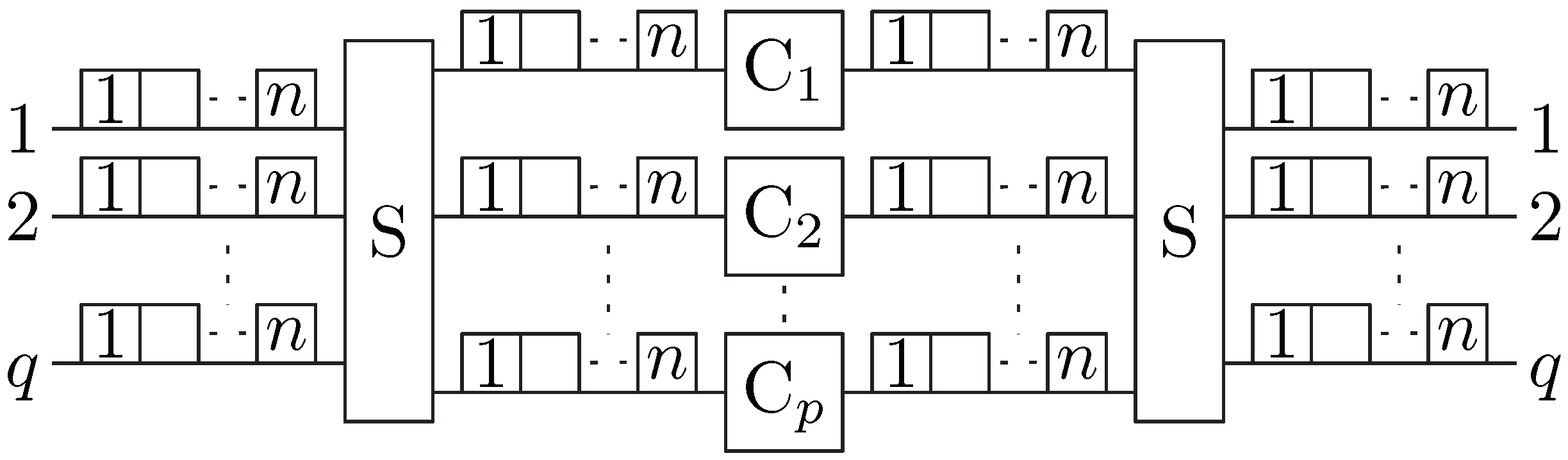
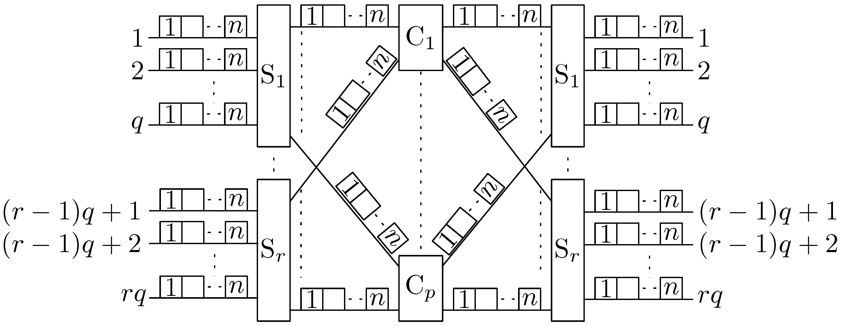
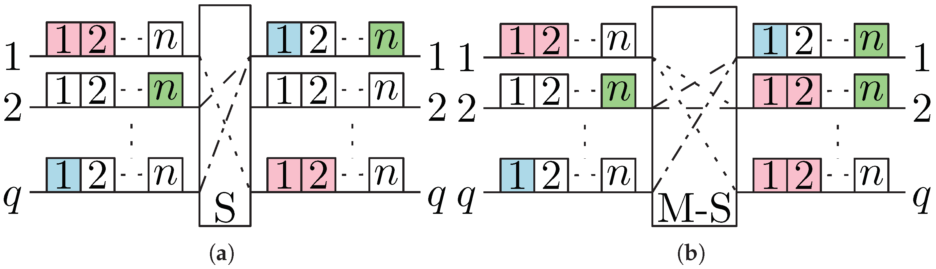
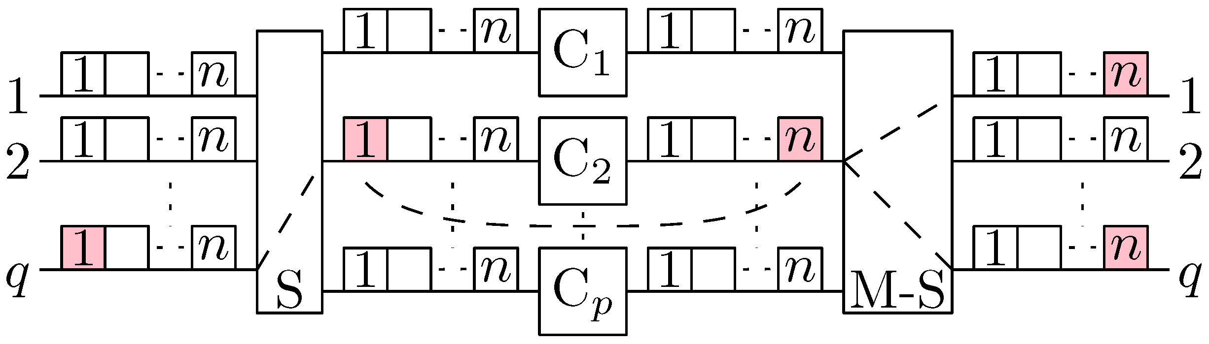
2. Multicast S-C-S Switching Fabrics

The SCS1 symmetrical three-stage switching fabric is presented in Figure 1, while in Figure 2 the SCS2 unicast switching fabric is shown. We will denote these structures using the common notation SCS q , p , r , n , where q 2 is the number of input links connected to the one input-stage space switch and, at the same time, the number of output links from one last-stage switch; p 1 is the number of middle-stage conversion switches; r 1 is the number of space switches in the outer stages; and n 2 is the number of DSUs in the input, output, and interstage links. The SCS1 switching fabric can be treated as a special case of an SCS2 switching fabric in which r = 1 , and therefore the common notation is possible (SCS1 ≡ SCS q , p , 1 , n ).
The input-stage space switches in SCS q , p , r , n are of capacity q × p links and each link has n DSUs; therefore, each switch is of capacity q n × p n DSUs. Similarly, the output-stage switches are of capacity p × q links and p n × q n DSUs. The switching fabric SCS q , p , r , n has a capacity of N × N where N = q n r ( N = q n for SCS1). In the middle stage, there are p switches with the conversion of a capacity r × r links and r n × r n DSUs. We assume that middle-stage switches have full-range conversion capability [40].
In this article, we propose a modification to SCS q , p , r , n involving the integration of multicast capability into each switch within the output stage. The contrast between the operations of unicast (S) and multicast (M-S) space switches in the third stage is depicted in Figure 3. Our proposition asserts that for each m-slot multicast connection, it is feasible to direct it from an input link to f s 3 output links without changing the DSU indices due to space switching. Here, the parameter f s 3 (or f in stage 3) signifies the desired number of output links within a single connection within the range of 1 f s 3 q . To illustrate, consider the M-S switch in Figure 3: a connection originating from input 1 can be routed to multiple outputs (such as links 2 and q in the provided example) while keeping the slot indices (1, 2) unaltered. In this particular multicast connection scenario, f s 3 is set to two.
Additionally, we introduce another parameter, f, which designates the maximum number of output links that any multicast connection within the switching fabric might require. It is evident that 1 f s 3 f q .
According to the proposition of [43], we will call this multicast switching fabric M-SCS and denote it as M-SCS q , p , r , n , f . M-SCS switching fabric architectures with r = 1 (M-SCS1) and r > 1 (M-SCS2) are shown in Figure 4 and Figure 5, respectively.
The combinatorial properties of the nonblocking SCS1 and SCS2 architectures have been investigated [40,41,42], but none have been studied for the M-SCS architectures. In this paper, the SSNB conditions for M-SCS1 and M-SCS2 with limited multicast are presented.

3. Problem Statement

The multicast nonblocking conditions will be described and derived using the means used in [40] for unicast S-C-S switching fabrics. Both S-C-S switching fabric architectures considered in this paper switch m-slot multicast connections. The number of DSUs occupied by one m-slot multicast connection is limited to m max , that is, 1 m m max n [40,41,42]. One connection occupies m adjacent DSUs. An m-slot connection can be set up, extending from the input link to the f s 3 output links. In particular, this connection assumes a point-to-point configuration when f s 3 is equal to one, while it transforms into a multicast configuration for f s 3 values greater than one. The newly established m-slot connection, which spans from the input link to the f s 3 output links, requires the identification of a middle-stage switch responsible for converting the DSUs in the designated domain. This switch must redirect the signal from the DSUs utilized on the input link to match those requested on the output link. Space switches located in the outermost stages are utilized to route an m-slot connection from the input link to the corresponding middle-stage switch and, subsequently, from the middle-stage switch to the group of f s 3 output links connected to an output-stage switch. The middle-stage switch selected to establish the new connection must have appropriate and available DSUs within its corresponding input and output links, ensuring that they are not already occupied by other connections [40,41,42].
For example, the 2-cast 1-slot connection in M-SCS1 switching fabric is shown in Figure 4. This connection is set up from input link q to output 2 in the input-stage space switch, then slot number 1 is converted to slot number n in the second middle-stage switch, and finally the output-stage switch connects its input link 2 to the output links number 1 and q. In turn, Figure 5 shows an example of a two-cast two-slot connection (marked in pink), which is established through the middle-stage switch C1. The same figure shows a single slot connection (in blue) at the input site that uses one of the slots with the same index as the multicast connection (so-called intersection). This means that both connections are mutually blocked in the links between the first and second stages and must be set up through two different links (and switches in the middle stage). We can also say that the establishment of one of the exemplary connections causes the blocking of the middle-stage switch for the other of these connections. These facts are used to determine the nonblocking conditions.
The goal of this paper is to derive the sufficient and necessary conditions for an f-cast SSNB M-SCS q , p , r , n , f architecture. Specifically, our problem can be stated as: how many middle-stage switches, namely, p, are sufficient and necessary for an M-SCS q , p , r , n , f architecture to be f-cast SSNB when parameters q, r, n, and f are provided.

4. SSNB Conditions

4.1. Potential Blocking and Nonblocking Connections

The proofs of nonblocking conditions are based on the methodology provided in [40,41,42]. This methodology is based on the construction of the worst-case scenario. We calculate the value of p, representing the middle-stage switches capable of establishing m-slot multicast connections, where 1 m m max n , with multicast functionality limited to the switches located in the third stage. In the worst-case scenario, we use sets of potential blocking and nonblocking connections. In fact, we use terms of potential blocking connections at the input site and at the output site, as well as potential nonblocking connections at the input site and at the output site. These terms are related to the new connection (interchangeably called a new request) [41,42]. Let us assume that a new f s 3 -cast connection has to be set up in the M-SCS1 switching fabric. Every connection that intersects with the new request (is set up from the same input-stage switch and has at least one DSU index in common) at the interstage links between the first- and second-stage switches will be called a potential blocking connection at the input site. Additionally, every connection that intersects with the new connection (is set up to the same output-stage switch and has at least one DSU index in common) at the interstage links between the middle-stage and the output-stage switches is called a potential blocking connection at the output site. When two different m-slot connections block each other, then they must be set up through different middle-stage switches (see Figure 5) [41,42].
Every connection that has no common slot index with the new request is called a potential nonblocking connection, wherein we differentiate between potential nonblocking connections at the input site (it has no common slot index with the new request in the interstage links between the first- and second-stage switches) and potential nonblocking connections at the output site (it has no common slot index with the new request in the interstage links between the second- and third-stage switches) [41,42].
All potential blocking connections from the input site are called a set of such connections, while all potential blocking connections from the output site are called a set of potential blocking connections from the output site. The sets of potential blocking connections for the new request are denoted by B i n and B o u t at the input and output sites, respectively. A similar taxonomy is used for nonblocking connections, for which we define the sets of nonblocking connections from the input and the output site. The sets of potential nonblocking connections for the new request are denoted by N i n and N o u t at the input and output sites, respectively [41,42].
An example of sets of potential blocking and nonblocking connections in the M-SCS1 switching fabric is presented in Figure 6. As already mentioned, the nonblocking conditions are determined by constructing the worst-case scenario. In such a scenario, connections from set B i n are set up to set N o u t through a set of p 1 middle-stage switches (all these elements are marked in orange in the figure), while connections from set N i n are set up to set B o u t through a set of p 2 middle-stage switches (all these elements are marked in yellow in the figure). The worst-case scenario arises when the sets of the p 1 and p 2 middle-stage switches are disjointed [40].
For example, from Figure 6, connection c is set up from set B i n to set N o u t and can block the new connection m only at the input site (one index is in common and these connections cannot be set up through the same interstage link). In turn, connection a is set up from set N i n to set B o u t and can block the new request only at the output site (DSU number 2 is in common and these connections cannot be set up through the same interstage link). In the worst-case scenario, these two blocking connections do not block each other but are set up through different middle-stage switches. It should be mentioned that the maximum number of blocking connections can be obtained when each blocking connection uses as few slots as possible (that is, one according to assumption 1 m m max n ) and is a unicast connection [40].
In SSNB conditions, the maximum number of blocking connections that can be set up in the switching fabric must be discovered. This number is used to compute the necessary and sufficient count of middle-stage switches for which establishing each m-slot multicast connection is feasible, regardless of the selected search algorithm for the connecting path. The size of the B i n , B o u t , N i n , and N o u t sets must be known to determine the maximum number of blocking connections [41,42].
Similar considerations can be applied to M-SCS2 switching fabrics. In this scenario, there are r input- and output-stage switches. However, all possible blocking connections are established solely from a single input-stage switch (the same one from which the new connection originates) and/or directed toward just one output-stage switch (containing all necessary output links). All other connections are incapable of blocking the new connection within the M-SCS2 switching fabrics (refer to Figure 5) [40,41,42]. The sets of potential blocking and nonblocking connections in the M-SCS2 switching fabric are depicted in Figure 7 using a simplified schematic representation.

4.2. Number of Potential Blocking and Nonblocking Connections in M-SCS1

The number of potential blocking connections at the input site for the new f s 3 -cast connection is the maximum number of one-slot connections in input links that have one slot in common with the new request (see Figure 6). These connections are established from input links other than the one from which the new connection originates. We have q 1 such links, and in each of them m one-slot connections that intersect with the new connection can be set up. Therefore,
B i n = m ( q 1 ) .
The number of potential nonblocking connections at the input site is calculated as the maximum number of one-slot connections that can be set up from all input links in the input-stage switch and have no one slot in common with the new request (see again Figure 6). Therefore,
N i n = q ( n m ) .
The new connection is directed to the set of f s 3 outputs. Therefore, the potential blocking connections at the output site can be directed only to q f s 3 output links. In each of these links, the maximum number of one-slot connections that intersect with the new m-slot connection is equal to m. Therefore,
B o u t = m ( q f s 3 ) .
The multicast opportunity at the output-stage switch does not change the method of counting the maximum number of potential nonblocking connections at the output site. Therefore, the cardinality of set N o u t is equal to:
N o u t = q ( n m ) .

4.3. Number of Potential Blocking and Nonblocking Connections in M-SCS2

Taking into account the remarks in Section 4.1, we can conclude that the size of sets B i n and B o u t in M-SCS2 switching fabrics is the same as those in M-SCS1 (compare Figure 6 and Figure 7). In turn, sets N i n and N o u t contain more potential nonblocking connections than the corresponding sets in the M-SCS1 switching fabrics. This is because we must consider input and output links from the remaining switches in the outer stages. Therefore,
N i n = q ( n m ) + q n ( r 1 ) ,
and
N o u t = q ( n m ) + q n ( r 1 ) .

4.4. Number of Middle-Stage Switches Blocked in M-SCS1

In order to construct the worst-case scenario in the switching fabric, DSUs for potentially blocking connections are used to establish connections. These are connections that block the links for the new connection. Since every link carries the signal to a specific middle-stage switch, it can be said that the blocking connection blocks a specific middle-stage switch and the new connection cannot be established through this switch. Finding the nonblocking conditions means counting all connections that will block as many middle-stage switches as possible and adding another switch for the new connection.
We must consider four cases to determine the maximum number of middle-stage switches occupied by blocking connections. All these cases are schematically represented in Figure 8. In every case, potentially blocking DSUs are used to set up blocking connections. In the worst-case scenario, each blocking connection is set up through a separate interstage link and, as a consequence, through a separate middle-stage switch. All possible blocking connections from the input site are set through the maximum number of p 1 middle-stage switches, while all possible blocking connections from the output site are set through the maximum number of p 2 switches. In one case, an additional number of p 3 middle-stage switches is needed. These switches are inaccessible for the new m-slot multicast connection.
Case 1.
B i n N o u t and B o u t N i n .
This case is presented in Figure 8a. In this case, all blocking connections from the input site can be directed to outputs in N o u t through, at most, p 1 = B i n separate middle-stage switches. Additionally, all blocking connections at the output site can be set up from inputs in N i n through, at most, p 2 = B o u t different middle-stage switches. In the worst-case scenario, the set containing p 1 middle-stage switches and the set containing p 2 middle-stage switches are disjointed. That is, in this case, the maximum number of blocked middle-stage switches is equal to:
p b = p 1 + p 2 = B i n + B o u t .
We have to check when this case occurs. The implication of condition B i n N o u t in M-SCS1 switching fabrics as shown in (1) and (4) is that:
m ( q 1 ) q ( n m ) ,
and then:
m n q 2 q 1 .
Furthermore, deducing from (2) and (3), the condition B o u t N i n in M-SCS1 switching fabrics means:
m ( q f s 3 ) q ( n m ) ,
and, as a consequence,
m n q 2 q f s 3 .
It can be easily shown that n q 2 q 1 n q 2 q f s 3 for each 1 f s 3 f q . Therefore, conditions (9) and (11) can be reduced to one condition (9). The number of blocked middle-stage switches for the new f s 3 -cast m-slot connection in the M-SCS1 switching fabric is calculated for this case from (7) as:
p b = m ( q 1 ) + m ( q f s 3 ) = m ( 2 q f s 3 1 ) when 1 f s 3 f q and m n q 2 q 1 .
Example 1.
An example of the number of middle-stage switches blocked for Case 1 is presented in Figure 9. We have the following parameters for the switching fabric: q = 3 , n = 4 , m = 2 , and f s 3 = 2 . Conditions 1 f s 3 q and (9) are fulfilled for this set of parameters, and this means that it is Case 1. In the worst-case scenario, all B i n = m ( q 1 ) = 4 blocking connections from the input site can be established. These are connections that use DSUs marked as c, d, e, and g in Figure 9. They are established through p 1 = 4 middle-stage switches (in the worst-case scenario, every blocking connection is set through a separate switch). At the same time, blocking connections at the output site use DSUs marked as a and b. They are established through additional p 2 = B o u t = 2 middle-stage switches. It is evident that all these switches are unsuitable for establishing the new m-slot multicast connection. The total number of middle-stage switches that are blocked for the new multicast connection is equal to six, calculated from (12).
Case 2.
B i n N o u t and B o u t > N i n .
This case is presented in Figure 8b. Conditions B i n N o u t and B o u t > N i n drive to conditions (9) and
m > n q 2 q f s 3 .
Conditions (9) and (13) can be combined into a single condition:
n q 2 q f s 3 < m n q 2 q 1 .
However, it can be seen that condition (14) will never be met for 1 f s 3 . Therefore, the case where B i n N o u t and B o u t > N i n will never be fulfilled and it does not need to be considered further.
Case 3.
B i n > N o u t and B o u t N i n .
This case is presented in Figure 8c. Connections to slots in set N o u t are set up through, at most, p 1 = N o u t = q ( n m ) middle-stage switches. Moreover, connections to slots from set B o u t are set up through, at most, p 2 = B o u t = m ( q f s 3 ) middle-stage switches. The sets of p 1 and p 2 middle-stage switches are disjointed in the worst-case scenario. That is, in this case, the maximum number of blocked middle-stage switches is equal to:
p b = p 1 + p 2 = q ( n m ) + m ( q f s 3 ) = n q m f s 3 .
In this case, conditions (11) and
m > n q 2 q 1
must be fulfilled. Conditions (11) and (16) can be combined into a single condition:
n q 2 q 1 < m n q 2 q f s 3 .
This condition is satisfied for all 1 < f s 3 . Finally, we can conclude that the number of middle-stage switches blocked in this case is as follows:
p b = n q m f s 3 when 1 < f s 3 f q and n q 2 q 1 < m n q 2 q f s 3 .
Example 2.
An example of the number of middle-stage switches blocked for Case 3 is presented in Figure 10. We have the following parameters for the switching fabric: q = 3 , n = 3 , m = 2 , and f s 3 = 2 . Conditions 1 f s 3 q and (17) are fulfilled for this set of parameters, and this means that it is Case 3. In the worst-case scenario, only N o u t = q ( n m ) = 3 blocking connections from the input site can be set up. These are connections that use DSUs marked as c, d, and e in Figure 10. They are established through p 1 = 3 middle-stage switches. At the same time, blocking connections at the output site use DSUs marked as a and b. They are established through additional p 2 = B o u t = 2 middle-stage switches. It is evident that all these switches are not suitable for establishing the new m-slot multicast connection. The total number of middle-stage switches that are blocked for the new multicast connection is equal to five, calculated from (18).
Case 4.
B i n > N o u t and B o u t > N i n .
This case is presented in Figure 8d. In this situation, blocking connections from set B i n to all slots in N o u t can be achieved using a maximum of p 1 = N o u t switches. Only some of the input slots from B i n can be used. Similarly, from all slots from set N i n , it is possible to set up blocking connections to slots from set B o u t through, at most, p 2 = N i n middle-stage switches. However, only a part of the output slots from B o u t can be used.
We still have B i n N o u t DSUs that are possible to set up connections at the input site. Connections can also be established at the output site to B o u t N i n DSUs. The new connection is blocked by all these connections at the input and output sites simultaneously. This means that we can set up, at most, min B i n N o u t ; B o u t N i n additional blocking connections. These connections are set up from input set B i n to set B o u t . This also means that we need p 3 = min B i n N o u t ; B o u t N i n additional middle-stage switches in the worst-case scenario.
The minimum value can be determined from the two considered quantities: B i n N o u t and B o u t N i n . From (1) and (4), we have B i n N o u t = m ( 2 q 1 ) n q . Similarly, from (2) and (3) we have B o u t N i n = m ( 2 q f s 3 ) n q . Therefore, for each 1 f s 3 f q ,
min m ( 2 q 1 ) n q ; m ( 2 q f s 3 ) n q = m ( 2 q f s 3 ) n q ,
and
p 3 = m ( 2 q f s 3 ) n q = B o u t N i n .
Finally, the number of middle-stage switches blocked for the new connection is as follows.
p b = p 1 + p 2 + p 3 = N o u t + N i n + B o u t N i n = N o u t + B o u t .
Conditions B i n > N o u t and B o u t > N i n are satisfied for (13) and (16). However, we can see that for all 1 f s 3
n q 2 q f s 3 n q 2 q 1 .
Therefore, conditions (13) and (16) can be reduced to only one (13) for 1 f s 3 f q . Finally, from (21) we have, in this case,
p b = n q m f s 3 when 1 f s 3 f q and n q 2 q f s 3 < m .
Example 3.
An example of the number of middle-stage switches blocked for Case 4 is presented in Figure 11. We have the following parameters for the switching fabric: q = 3 , n = 5 , m = 4 , and f s 3 = 2 . Conditions 1 f s 3 q and (13) are fulfilled for this set of parameters, and this means that it is Case 4. In the worst-case scenario, it is feasible to set up only N o u t = q ( n m ) = 3 blocking connections from the input site. These are connections that use DSUs marked as d, e, and g in Figure 11. They are established through p 1 = 3 middle-stage switches. At the same time, blocking connections at the output site use DSUs marked as a, b, and c. They are established through additional p 2 = N i n = 3 middle-stage switches. We still have five unused DSUs in B i n and one unused DSU in B o u t . These DSUs can be used to establish one more blocking connection ( min 5 ; 1 ) that blocks the new multicast connection at the input and output sites simultaneously. This connection is marked as h in Figure 11 and uses one more middle-stage switch ( p 3 = B o u t N i n = 1 ). It can be seen that all these switches cannot be used to set up the new m-slot multicast connection. The total number of middle-stage switches that are blocked for the new multicast connection is equal to seven, calculated from (23).
The number of middle-stage switches blocked for the new connection for Cases 3 and 4 are calculated from (18) and (23), respectively, but they can easily be combined into one single case. Therefore, we transform (18) and (23) into
p b = n q m f s 3 when 1 f s 3 f q and n q 2 q 1 < m .
Concluding the discussion, the number of middle-stage switches blocked for the new f s 3 -cast m-slot connection ( 1 f s 3 f q ) in the M-SCS1 switching fabric is calculated as follows:
p b M - SCS 1 = m ( 2 q f s 3 1 ) for m n q 2 q 1 n q m f s 3 for n q 2 q 1 < m n .

4.5. Number of Middle-Stage Switches Blocked in M-SCS2

In the case of M-SCS2 switching fabrics, we can observe that the cardinalities of sets N i n and N o u t are greater than those for sets B i n and B o u t , respectively. However, we can formally confirm this observation. Let us check when B i n N o u t and B o u t N i n in the M-SCS2 switching fabrics. From (1) and (6) we have m ( q 1 ) q ( n m ) + q n ( r 1 ) and, therefore,
m n r q 2 q 1 .
At the same time, the general condition m n must be satisfied. Let us check if r q 2 q 1 > 1 . This condition is true for every q > 1 and r > 1 . This means that conditions n r q 2 q 1 > n and (26) are always true. This conclusion confirms that B i n N o u t is always satisfied in M-SCS2 switching fabrics.
Similar considerations can be conducted for the condition B o u t N i n . In this case,
m n r q 2 q f s 3 .
This condition is satisfied for every q > 1 , r > 1 , and 1 f s 3 f q , and therefore condition B o u t N i n is always true. This means that only this one case with B i n N o u t and B o u t N i n must be considered for M-SCS2 switching fabrics.
Therefore, the number of middle-stage switches blocked for the new f s 3 -cast m-slot connection ( 1 f s 3 f q ) in the M-SCS2 switching fabrics is calculated similarly to (12) and is as follows:
p b M - SCS 2 = m ( 2 q f s 3 1 ) for 1 m n .

4.6. The Maximum Number of Blocked Middle-Stage Switches

The number of middle-stage switches blocked for the new connection is calculated from (25) and (28) in the worst-case scenario for the M-SCS1 and M-SCS2 switching fabrics, respectively. To set the nonblocking conditions, we have to find absolutely the highest number of blocked middle-stage switches for all possible new f-cast m-slot connections. This means
p b max M - SCS 1 = max 1 f q max 1 f s 3 f p b M - SCS 1 ,
for M-SCS1, where p b M - SCS 1 is calculated from (25) and
p b max M - SCS 2 = max 1 f q max 1 f s 3 f p b M - SCS 2 ,
for M-SCS2, where p b M - SCS 2 is calculated from (28).
Lemma 1.
The maximum number of middle-stage switches that are blocked in the M-SCS1 switching fabrics for the new f s 3 -cast ( 1 f s 3 f q ), m-slot connection, ( 1 m m max n ) is as follows:
p b max M - SCS 1 = 2 m ( q 1 ) for m n q 2 q 1 n q m for n q 2 q 1 < m n .
Lemma 2.
The maximum number of middle-stage switches that are blocked in the M-SCS2 switching fabrics for the new f s 3 -cast ( 1 f s 3 f q ), m-slot connection, ( 1 m m max n ) is as follows:
p b max M - SCS 2 = 2 m ( q 1 ) for 1 m n .
Proof. 
For M-SCS1 switching fabrics, it is easy to show from (25) that the number of blocked middle-stage switches depends linearly and inversely on f s 3 . Therefore, the maximum number for each 1 m n is obtained for f s 3 = 1 . The same is true for M-SCS2 switching fabrics (see (28)). □

4.7. Nonblocking Conditions

The maximum number of middle-stage switches blocked for the new request for the switching fabrics M-SCS1 and M-SCS2 is calculated from Lemma 1 and 2, respectively. This maximum number is obtained for f s 3 = 1 for both switching fabric architectures. This means that the worst-case scenario for multicast switching fabrics is exactly the same as that for SCS1 and SCS2 unicast switching fabrics. Therefore, we can summarize the discussion in Section 4.1, Section 4.2, Section 4.3, Section 4.4, Section 4.5 and Section 4.6 in the following conclusion.
Multicast switching fabrics M-SCS1 and M-SCS2 with limited multicast opportunity in the last-stage space switches are strict-sense nonblocking under exactly the same conditions as unicast SCS1 and SCS2 switching fabrics. Therefore, the SSNB conditions for the unicast SCS1 and SCS2 switching fabrics presented in [40] are also valid for the M-SCS1 and M-SCS2 switching fabrics, respectively. The proofs of Theorems 1 and 2 presented in [40] are also true, but the construction of the worst-case scenario for multicast connections is presented in this paper in Section 4.1, Section 4.2, Section 4.3, Section 4.4, Section 4.5 and Section 4.6 and in Lemmas 1 and 2.
In the proofs of the theorems from [40], the necessary and sufficient conditions are presented. The number of middle-stage switches must be greater than or equal to the maximum number of middle-stage switches blocked for the new request ( p b max M - SCS 1 for M-SCS1 and p b max M - SCS 2 for M-SCS2) plus one additional switch for the new m-slot connection. Furthermore, to ensure that every m-slot connection for each possible value of m can be established in the switching fabric, the absolute maximum of the number of middle-stage switches must be searched in the whole range of 1 m m max n . The proofs in [40] consider all these aspects, and therefore we present here the theorems for the multicast switching fabrics M-SCS1 and M-SCS2 without repeating proofs.
Theorem 1.
The three-stage M-SCS1 switching fabric with limited multicast opportunity in the last-stage space switch, presented in Figure 6, is strict-sense nonblocking for f s 3 -cast, 1 f s 3 f q , m-slot, and 1 m m max n connections, if and only if
p 2 m max ( q 1 ) + 1 for m max n q 2 q 1 n q n q 2 q 1 + 1 for m max n q 2 q 1 + 1 .
Theorem 2.
The three-stage M-SCS2 switching fabric with limited multicast opportunity in the last-stage space switches, presented in Figure 7, is strict-sense nonblocking for f s 3 -cast, 1 f s 3 f q , m-slot, and 1 m m max n connections, if and only if
p 2 m max ( q 1 ) + 1 .
It is clear that the numerical results and the relationship of the parameters p, n, m, q, and r presented in [40] are also valid for multicast switching fabrics with the opportunity to multicast only on switches in the last stage. This is because the nonblocking conditions do not depend on the value of f.

4.8. Numerical Results

4.8.1. M-SCS1 Switching Fabrics

In this particular scenario, the number of switches with conversion is determined using the formula outlined in Theorem 1. In a strict-sense nonblocking fabric, the count of switches exhibits a linear dependence on m max (with q held constant) when m max is less than or equal to n q / 2 q 1 . Within this range, p remains unaffected by variations in the number of DSUs within the links (n). Only when the value of m max surpasses n q / 2 q 1 does the number of switches in the middle stage become dependent on the parameters n and q, while m max no longer plays a role in its determination.
These points are easy to see on the chart in Figure 12. It shows how the number of conversion switches, p, changes with different values of m max , 1 m max n , for various combinations of n and q. When q is kept constant, the number of switches increases linearly until m max exceeds the value n q / 2 q 1 , at which point it levels off. For example, when n takes any value and q is set to five, the corresponding number of switches in the middle stage is as follows: p equals 9, 17, 41, 81, and 161 for m max values of 1, 2, 5, 10, and 20, respectively.
The graph in Figure 13 illustrates the relationship between the number of switches (p) and the number of DSUs on the links (n) in fabrics with a fixed capacity of N = n q = 400 . This constant capacity can be achieved by adjusting either n or q, with one increasing as the other decreases. In particular, as implied by the formula derived from Theorem 1, reducing the value of q leads to a reduction in p. For example, when N = 400 and m max = 20 , one has the option to select between two structures: one with n = 80 and q = 5 , resulting in a required p of 161; and the other with n = 100 and q = 4 , where this number decreases to p = 121 .
The slight variation in the line shape for the case of m max = 50 is due to the fact that, for the values of n = 50 and 80, m max exceeds the threshold n q / 2 q 1 . Consequently, the calculation of the number of switches p is determined using the second part of Formula (33) in these instances.

4.8.2. M-SCS2 Switching Fabrics

In the case of M-SCS2 switching fabrics, the number of middle-stage switches is determined via Theorem 2. In this scenario, the number of switches p is independent of both n and r. Furthermore, the smaller the value of q, the fewer switches are required in the central stage. In a network with fixed capacity N = n q r , it is possible to adjust the value of q by manipulating the other two parameters. Figure 14 illustrates the results for various M-SCS2 network configurations with a constant capacity of N = 400 . When q remains constant, the number of switches exhibits a linear relationship with m max . As q increases, the number of switches p also increases.
However, when designing a nonblocking M-SCS2 switching fabric, it is important to consider the specific objectives we want to achieve. For example, reducing the value of q will result in corresponding decreases or increases in the values of the other two parameters. In contrast, increasing the value of r leads to a decrease in n, which affects the maximum number of DSUs that can be used in a single connection ( m max ). Moreover, increasing the number of switches r in the outer stages enlarges the size of the conversion switches ( r × r ), which may not always be advantageous due to the associated construction costs.
Table 1 presents a comparison of various configurations between switching fabrics M-SCS1 and M-SCS2. In this table, we compile data on the smallest number of middle-stage switches for different combinations of n and m max . Specifically, we consider three different values for the number of DSUs in links (n) 50, 100, and 200, together with three different values for m max (2, 5, and 10). This comparison is made in three distinct switching fabric capacities: 400, 800, and 1000 DSUs, respectively.
The findings reveal that M-SCS2 fabrics achieve the lowest number of middle-stage switches when q is set to its smallest possible value of two.
In the context of M-SCS2 fabrics, when n equals 200 and N equals 400, the number of switches in the outer stages must be limited to 1 (according to the requirement that q 2 ). This effectively results in the structure of an M-SCS1 fabric.
Furthermore, for M-SCS2 switching fabrics, when n is set to 200 and the intended capacity is N equal to 1000, achieving the minimum number of switches p with q set to two requires that r be equal to N / n q .
The results presented in Table 1 indicate that the number of middle-stage switches in M-SCS2 switching fabrics is significantly lower than that in M-SCS1. However, it should be noted that conversion switches in M-SCS1 fabrics have only one input link and one output link, each with n DSUs. In M-SCS2 fabrics, the switches have r input and output links, each also equipped with n DSUs. Therefore, regardless of the signal multiplexing technique on the link, the conversion switches in the M-SCS2 fabrics will have a more complex structure. Consequently, when selecting the appropriate multicast S-C-S switching fabric structure, consideration should be given to both the number of switches and their cost.

5. Conclusions

The paper introduces two designs for switching fabrics that handle multicast connections. These fabrics are used to set up connections that span multiple slots that are placed one after another. This kind of setup is commonly used in elastic optical networks. However, it is important to note that this research is more theoretical and general in nature. It assumes that the transmission medium is divided into slots, whereby the slot realization domain can be arbitrary.
Both of the examined structures for multicast switching fabrics are derived from the concepts of fabrics designed for point-to-point connections, which were previously discussed [40]. The configurations of the mentioned fabrics involve the utilization of space switches in the outer stages of a three-stage fabric, along with switches equipped with conversion functionality in the middle stage. Such switching fabrics are called S-C-S fabrics, and the two considered architectures are named SCS1 and SCS2 [41,42].
This paper posits that the space switches in the third stage possess the capability to establish connections between a single input and multiple (even all) outputs of the switch. This enables the implementation of multicast connections across the entire switching fabric. Two multicast switching fabrics are derived from the SCS1 and SCS2 fabric concepts. The one based on SCS1 is referred to as the M-SCS1 switching fabric, while the multicast switching fabric employing the SCS2 structure is known as M-SCS2. Additionally, the assumption is made that the conversion switches can interchange the slot numbers used at the input and output of the switching fabric for a given connection [41,42].
This paper introduces a method to create the worst-case scenario within the M-SCS1 and M-SCS2 fabrics. This scenario serves as the foundation for establishing the strict-sense nonblocking conditions of multicast S-C-S switching fabrics. In this paper, strict-sense nonblocking conditions are derived, specifically the necessary and sufficient value of p, which represents the middle-stage conversion switches, for symmetrical multicast Space-Conversion-Space switching fabrics with continuous multislot connections.
This study demonstrates that the architectures of the multicast switching fabrics are identical to those of the unicast fabrics. The only difference lies in the capability to establish multicast connections within the third-stage switches. This finding is significant because of the greater complexity of conversion switches compared with space switches [40]. The fact that both unicast and multicast fabrics demand an equal number of conversion switches implies that implementing multicast switching fabrics can be achieved without significant additional costs.
The research findings outlined in this paper lead to the conclusion that the proofs of Theorems 1 and 2, as well as the numerical results presented in [40] for unicast fabrics, remain applicable to the multicast fabrics introduced in this article. However, these conclusions were drawn during the process of analyzing the generation of the worst-case scenario in the M-SCS1 and M-SCS2 switching fabrics, as detailed in Section 4.4 and Section 4.5.
Although the article has a theoretical nature, it can serve as a guiding reference for individuals seeking to construct multicast switching fabrics for multislot connections within continuous time slots, frequency slots, or other selected domains. In particular, there are no requirement to re-evaluate the types and quantities of switches, with or without conversion capabilities, necessary for multicast fabrics. The required number of switches can be determined from the theorems outlined in this paper.
The research findings presented here serve as a foundational stepping stone for future investigations of switching fabrics designed for continuous multislot connections. In subsequent studies, fabrics with the potential for multicast functionality in additional stages will also be explored.

Funding

This research was funded by the Ministry of Science and Higher Education (Poland), grant number 0313/SBAD/1310.

Data Availability Statement

Data sharing not applicable.

Conflicts of Interest

The author declares no conflict of interest.

References

  1. Stare, E.; Munier, F.; Pham Van, D. 5G Multicast-Broadcast for Group Communication: Why It Matters and How It Works. Available online: https://www.ericsson.com/en/blog/2022/12/multicast-broadcast-group-communication (accessed on 12 September 2023).
  2. Stasiak, M.; Sobieraj, M.; Zwierzykowski, P. Modeling of Multi-Service Switching Networks with Multicast Connections. IEEE Access 2022, 10, 5359–5377. [Google Scholar] [CrossRef]
  3. Zhao, L.; Shi, P.; Zhang, H. Bi-Directional Benes With Large Port-Counts and Low Waveguide Crossings for Optical Network-on-Chip. IEEE Access 2021, 9, 115788–115800. [Google Scholar] [CrossRef]
  4. Khattak, M.K.; Tang, Y.; Fahim, H.; Rehman, E.; Majeed, M.F. Effective Routing Technique: Augmenting Data Center Switch Fabric Performance. IEEE Access 2020, 8, 37372–37382. [Google Scholar] [CrossRef]
  5. Wu, C.C.; Qiao, L.; Chen, Q. Design of a 640-Gbps Two-Stage Switch Fabric for Satellite On-Board Switches. IEEE Access 2020, 8, 68725–68735. [Google Scholar] [CrossRef]
  6. Lin, J.; Li, Y.; Shen, G. Clos-based All-optical Switching Architecture Supporting Mixed Unicast & Multicast Datacenter Services. In Proceedings of the 2023 Opto-Electronics and Communications Conference (OECC), Shanghai, China, 14 August 2023; pp. 1–3. [Google Scholar] [CrossRef]
  7. Listanti, M.; Roveri, A. Switching structures for ATM. Comput. Commun. 1989, 12, 349–358. [Google Scholar] [CrossRef]
  8. Lee, T.T. Non-blocking copy networks for multicast packet switching. In Proceedings of the 1988 International Zurich Seminar on Digital Communications—Mapping New Applications onto New Technologies, Zurich, Switzerland, 8–10 March 1988; pp. 221–229. [Google Scholar]
  9. Hui, J.Y. Switching and Traffic Theory for Integrated Broadband Networks; Springer: New York, NY, USA, 1990. [Google Scholar] [CrossRef]
  10. Clos, C. A study of non-blocking switching networks. Bell Syst. Tech. J. 1953, 32, 406–424. [Google Scholar] [CrossRef]
  11. Beneš, V.E. On rearrangeable three-stage connecting networks. Bell Syst. Tech. J. 1962, 41, 1481–1492. [Google Scholar] [CrossRef]
  12. Cantor, D.G. On non-blocking switching networks. Networks 1971, 1, 367–377. [Google Scholar] [CrossRef]
  13. Pattavina, A. Switching Theory: Architecture and Performance in Broadband ATM Networks; John Wiley & Sons, Ltd.: Chichester, UK, 1998. [Google Scholar] [CrossRef]
  14. Hwang, F.K. The Mathematical Theory of Nonblocking Switching Networks, 2nd ed.; World Scientific Publishing Company: Singapore, 2004. [Google Scholar]
  15. Kabaciński, W. Nonblocking Electronic and Photonic Switching Fabrics; Springer: Boston, MA, USA, 2005. [Google Scholar]
  16. Jajszczyk, A.; Jekel, G. A new concept-repackable networks. IEEE Trans. Commun. 1993, 41, 1232–1237. [Google Scholar] [CrossRef]
  17. Kabaciński, W.; Danilewicz, G. Wide-sense and strict-sense nonblocking operation of multicast multi-log2N switching networks. IEEE Trans. Commun. 2002, 50, 1025–1036. [Google Scholar] [CrossRef]
  18. Yu, C.; Jiang, X.; Horiguchi, S.; Guo, M. Overall Blocking Behavior Analysis of General Banyan-Based Optical Switching Networks. IEEE Trans. Parallel Distrib. Syst. 2006, 17, 1037–1047. [Google Scholar] [CrossRef]
  19. Yang, Y.; Wang, J. On blocking probability of multicast networks. IEEE Trans. Commun. 1998, 46, 957–968. [Google Scholar] [CrossRef]
  20. Stasiak, M.; Zwierzykowski, P.; Głąbowski, M. Blocking probability in the multi-service switching networks with multicast traffic. In Proceedings of the 2000 10th Mediterranean Electrotechnical Conference. Information Technology and Electrotechnology for the Mediterranean Countries, MeleCon 2000 (Cat. No.00CH37099), Lemesos, Cyprus, 29–31 May 2000; Volume 2, pp. 868–871. [Google Scholar] [CrossRef]
  21. Yang, Y.; Masson, G. Nonblocking broadcast switching networks. IEEE Trans. Comput. 1991, 40, 1005–1015. [Google Scholar] [CrossRef]
  22. Lea, C.T. Multi-log2N networks and their applications in high-speed electronic and photonic switching systems. IEEE Trans. Commun. 1990, 38, 1740–1749. [Google Scholar] [CrossRef]
  23. Shyy, D.J.; Lea, C.T. Log2(N,m,p) strictly nonblocking networks. IEEE Trans. Commun. 1991, 39, 1502–1510. [Google Scholar] [CrossRef]
  24. Danilewicz, G.; Kabaciński, W.; Rajewski, R. The New Banyan-Based Switching Fabric Architecture Composed of Asymmetrical Optical Switching Elements. In Proceedings of the GLOBECOM 2009—2009 IEEE Global Telecommunications Conference, Honolulu, HI, USA, 4 March 2009; pp. 1–6. [Google Scholar] [CrossRef]
  25. Hwang, F. Choosing the best logk(N,m,P) strictly nonblocking networks. IEEE Trans. Commun. 1998, 46, 454–455. [Google Scholar] [CrossRef]
  26. Hwang, F.; Jajszczyk, A. On Nonblocking Multiconnection Networks. IEEE Trans. Commun. 1986, 34, 1038–1041. [Google Scholar] [CrossRef]
  27. Tscha, Y.; Lee, K.H. Nonblocking conditions for multi-log2N multiconnection networks. In Proceedings of the [Conference Record] GLOBECOM ’92-Communications for Global Users, Orlando, FL, USA, 6–9 December 1992; Volume 3, pp. 1600–1604. [Google Scholar] [CrossRef]
  28. Das, S.; Parulkar, G.; McKeown, N. Rethinking IP core networks. IEEE/OSA J. Opt. Commun. Netw. 2013, 5, 1431–1442. [Google Scholar] [CrossRef]
  29. Cisco Annual Internet Report (2018–2023) White Paper. Available online: https://www.cisco.com/c/en/us/solutions/collateral/executive-perspectives/annual-internet-report/white-paper-c11-741490.html (accessed on 20 May 2022).
  30. Jinno, M.; Takara, H.; Kozicki, B.; Tsukishima, Y.; Sone, Y.; Matsuoka, S. Spectrum-efficient and scalable elastic optical path network: Architecture, benefits, and enabling technologies. IEEE Commun. Mag. 2009, 47, 66–73. [Google Scholar] [CrossRef]
  31. Gerstel, O.; Jinno, M.; Lord, A.; Yoo, S.J.B. Elastic optical networking: A new dawn for the optical layer? IEEE Commun. Mag. 2012, 50, S12–S20. [Google Scholar] [CrossRef]
  32. Tomkos, I.; Azodolmolky, S.; Sole-Pareta, J.; Careglio, D.; Palkopoulou, E. A tutorial on the flexible optical networking paradigm: State of the art, trends, and research challenges. Proc. IEEE 2014, 102, 1317–1337. [Google Scholar] [CrossRef]
  33. Liew, S.C.; Lee, T.T. Principles of Broadband Switching and Networking; Wiley Series in Telecommunications and Signal Processing; Wiley: Hoboken, NJ, USA, 2010. [Google Scholar]
  34. Iniewski, K.; Mccorsky, C.; Minoli, D. Network Infrastructure and Architecture: Designing High-Availability Networks; Wiley: Hoboken, NJ, USA, 2008. [Google Scholar]
  35. Recommendation G.694.1. In Spectral Grids for WDM Applications: DWDM Frequency Grid; International Telecommunication Union (ITU-T): Geneva, Switzerland, 2020; Available online: https://www.itu.int/rec/T-REC-G.694.1/en (accessed on 11 October 2023).
  36. Niestegge, G. Nonblocking multirate switching networks. In Proceedings of the 5th ITC Seminar, Lake Como, Italy, 4–8 May 1987; pp. 449–458. [Google Scholar]
  37. Kabaciński, W. On nonblocking switching networks for multichannel connections. IEEE Trans. Commun. 1995, 43, 222–224. [Google Scholar] [CrossRef]
  38. Liew, S.C.; Ng, M.H.; Chan, C.W. Blocking and nonblocking multirate Clos switching networks. IEEE/ACM Trans. Netw. 1998, 6, 307–318. [Google Scholar] [CrossRef]
  39. Turner, J.S.; Melen, R. Multirate Clos networks. IEEE Commun. Mag. 2003, 41, 38–44. [Google Scholar] [CrossRef]
  40. Danilewicz, G.; Kabaciński, W.; Rajewski, R. Strict-sense nonblocking space-wavelength-space switching fabrics for elastic optical network nodes. IEEE J. Opt. Commun. Netw. 2016, 8, 745–756. [Google Scholar] [CrossRef]
  41. Danilewicz, G. Asymmetrical Space-Conversion-Space SCS1 Strict-Sense and Wide-Sense Nonblocking Switching Fabrics for Continuous Multislot Connections. IEEE Access 2019, 7, 107058–107072. [Google Scholar] [CrossRef]
  42. Danilewicz, G. Supplement to “Asymmetrical Space-Conversion Space SCS1 Strict-Sense and Wide-Sense Nonblocking Switching Fabrics for Continuous Multislot Connections”—The SCS2 Switching Fabrics Case. IEEE Access 2019, 7, 167577–167583. [Google Scholar] [CrossRef]
  43. Lin, B.C. Nonblocking conditions for a multicast WSW architecture based on subtree scheme for elastic optical networks. Opt. Switch. Netw. 2022, 44, 100660. [Google Scholar] [CrossRef]
  44. Lin, B.C. Rearrangeability and repackability of a multicast wavelength-space-wavelength elastic optical network. Opt. Switch. Netw. 2023, 50, 100741. [Google Scholar] [CrossRef]
  45. Zhang, P.; Li, J.; Guo, B.; He, Y.; Chen, Z.; Wu, H. Comparison of node architectures for elastic optical networks with waveband conversion. China Commun. 2013, 10, 77–87. [Google Scholar]
  46. Chen, Y.; Li, J.; Zhu, P.; Niu, L.; Xu, Y.; Xie, X.; He, Y.; Chen, Z. Demonstration of Petabit scalable optical switching with subband-accessibility for elastic optical networks. In Proceedings of the OptoElectronics and Communication Conference and Australian Conference on Optical Fibre Technology, Melbourne, VIC, Australia, 6–10 July 2014. [Google Scholar]
  47. Kabaciński, W.; Michalski, M.; Rajewski, R. Strict-sense nonblocking W-S-W node architectures for elastic optical networks. J. Light. Technol. 2016, 34, 3155–3162. [Google Scholar] [CrossRef]
  48. Kabaciński, W.; Michalski, M.; Rajewski, R.; Żal, M. Optical datacenter networks with elastic optical switches. In Proceedings of the IEEE ICC 2017, Paris, France, 21–25 May 2017. [Google Scholar]
  49. Wang, Q.; Chen, L.K. Performance analysis of multicast traffic over spectrum elastic optical networks. In Proceedings of the Optical Fiber Communication Conference, Los Angeles, CA, USA, 4–8 March 2012. [Google Scholar]
  50. Lin, R.; Zuckerman, M.; Shen, G.; Zhong, W.-D. Design of light-tree based optical inter-datacenter networks. J. Opt. Commun. Netw. 2013, 5, 1443–1455. [Google Scholar] [CrossRef]
  51. Gong, L.; Zhou, X.; Liu, X.; Zhao, W.; Lu, W.; Zhu, Z. Efficient resource allocation for all-optical multicasting over spectrum-sliced elastic optical networks. J. Opt. Commun. Netw. 2013, 5, 836–847. [Google Scholar] [CrossRef]
  52. Kmiecik, W.; Goścień, R.; Walkowiak, K.; Klinkowski, M. Two-layer optimization of survivable overlay multicasting in elastic optical networks. Opt. Switch. Netw. 2014, 14, 164–178. [Google Scholar] [CrossRef]
  53. Ruiz, M.; Velasco, L. Performance evaluation of light-tree schemes in flexgrid optical networks. IEEE Commun. Lett. 2014, 18, 1731–1734. [Google Scholar] [CrossRef]
  54. Yang, L.; Gong, L.; Zhou, F.; Cousin, B.; Molnár, M.; Zhu, Z. Leveraging light forest with rateless network coding to design efficient all-optical multicast schemes for elastic optical networks. J. Light. Technol. 2015, 33, 3945–3955. [Google Scholar] [CrossRef]
  55. Fan, Z.; Li, Y.; Shen, G.; Chan, C.C.-K. Dynamic resource allocation for all-optical multicast based on sub-tree scheme in elastic optical networks. In Proceedings of the Optical Fiber Communication Conference, Anaheim, CA, USA, 20–24 March 2016. [Google Scholar]
  56. Fan, Z.; Li, Y.; Shen, G.; Chan, C.C.-K. Distance-adaptive spectrum resource allocation using subtree scheme for all optical multicasting in elastic optical networks. J. Light. Technol. 2017, 35, 1460–1468. [Google Scholar] [CrossRef]
  57. Cai, A.; Xu, K.; Zukerman, M. Comparison of different multicast approaches in elastic optical networks. In Proceedings of the ICTON 2018, Bucharest, Romania, 1–5 July 2018. [Google Scholar]
  58. Kabaciński, W.; Michalski, M.; Abdulsahib, M. Wide-sense nonblocking elastic optical switch. Opt. Switch. Netw. 2017, 25, 71–79. [Google Scholar] [CrossRef]
Figure 1. Symmetrical SCS1 switching fabric.
Electronics 12 04265 g001
Figure 2. Symmetrical SCS2 switching fabric.
Electronics 12 04265 g002
Figure 3. An example of (a) unicast and (b) multicast output-stage space switch operation; DSUs belonging to the same connection are marked with the same color.
Electronics 12 04265 g003
Figure 4. M-SCS1, a multicast switching fabric based on the SCS1 architecture with multicast capability in the third-stage switch and an example of a two-cast one-slot connection; DSUs belonging to the same connection are marked with the same color.
Electronics 12 04265 g004
Figure 5. An illustration of the M-SCS2 switching fabric architecture, denoted M-SCS ( q = 2 , p = 2 , r = 2 , n = 4 , f = 2 ), along with an example showcasing two mutually blocking connections; DSUs belonging to the same connection are marked with the same color.
Electronics 12 04265 g005
Figure 6. An example of sets of potential blocking and nonblocking connections in the M-SCS1 switching fabric for the new multicast connection; DSUs belonging to the same connection are marked with the same color.
Electronics 12 04265 g006
Figure 7. A scheme of sets of potential blocking and nonblocking connections in the M-SCS2 switching fabric (only important DSUs in interstage links are marked); DSUs belonging to the same connection are marked with the same color.
Electronics 12 04265 g007
Figure 8. Four cases to determine the maximum number of blocked middle-stage switches; all cases are described later in the paper.
Electronics 12 04265 g008
Figure 9. An example for Case 1 is a switching fabric with q = 3 , n = 4 , m = 2 , and f s 3 = 2 ; DSUs belonging to the same connection are marked with the same color.
Electronics 12 04265 g009
Figure 10. An example for Case 3 is a switching fabric with q = 3 , n = 3 , m = 2 , and f s 3 = 2 ; DSUs belonging to the same connection are marked with the same color.
Electronics 12 04265 g010
Figure 11. An example for Case 4 is a switching fabric with q = 3 , n = 5 , m = 4 , and f s 3 = 2 ; DSUs belonging to the same connection are marked with the same color.
Electronics 12 04265 g011
Figure 12. Number of switches with conversion in the middle stage of M-SCS1 switching fabrics with different values of q and n.
Electronics 12 04265 g012
Figure 13. Number of switches with conversion in the middle stage of M-SCS1 switching fabrics with N = n q = 400 and different values of m max and q = 400 / n .
Electronics 12 04265 g013
Figure 14. Number of switches with conversion in the middle stage versus m max in M-SCS2 switching fabrics with N = n q r = 400 and different values of r, q, and n.
Electronics 12 04265 g014
Table 1. Characteristics of M-SCS1 and M-SCS2 switching fabrics achieving the minimum conversion switch count p for specific values of N, n, and m max .
M-SCS1, r = 1 M-SCS2
n m max N = rnq q p r q p
502400829425
8001661825
100020771025
54008714211
800161518211
10002019110211
1040081414221
800163018221
10002038110221
1002400413225
800829425
10001037525
54004312211
8008714211
100010915211
104004612221
80081414221
1000101815221
2002400251 25
800413225
10005173 * 25
54002111 211
8004312211
10005413 * 211
104002211 221
8004612221
10005813 * 221
Note: : When r = 1, it corresponds to M-SCS1. *: In these cases, N = nqr is equal to 1200.
Disclaimer/Publisher’s Note: The statements, opinions and data contained in all publications are solely those of the individual author(s) and contributor(s) and not of MDPI and/or the editor(s). MDPI and/or the editor(s) disclaim responsibility for any injury to people or property resulting from any ideas, methods, instructions or products referred to in the content.

