Article

An Efficient Path Planning Method for the Unmanned Aerial Vehicle in Highway Inspection Scenarios

1
Certification Management Office of the Ministry of Information and Cybersecurity, National Information Center, Beijing 100045, China
2
Beijing Institute of Electronic Science and Technology (BESTI), Beijing 100070, China
*
Author to whom correspondence should be addressed.
Electronics 2023, 12(20), 4200; https://doi.org/10.3390/electronics12204200
Submission received: 29 August 2023 / Revised: 22 September 2023 / Accepted: 4 October 2023 / Published: 10 October 2023
(This article belongs to the Special Issue New Advances in Distributed Computing and Its Applications)

Abstract

:
Unmanned aerial vehicles (UAVs) have received widespread attention due to their flexible deployment characteristics. Automated airports equipped with UAVs are expected to become important equipment for improving quality and reducing costs in many inspection scenarios. This paper focuses on the automated inspection business of UAVs dispatched by automated airports in highway scenarios. On the basis of considering the shape of highway curves, inspection targets, and the energy consumption characteristics of UAVs, planning the flight parameters of UAVs is of great significance for ensuring the effectiveness of the inspection process. This paper first sets the inspection path points for the UAV based on highway curves, and then proposes an efficient heuristic method for the nonlinear non-convex parameter optimization problem, through which the parameters of the UAV’s inspection altitude, hovering altitude, and flight speed are planned. Simulation and analysis show that the proposed method possesses good parameter planning efficiency. By combining several existing trajectory planning methods, e.g., the traversal method, the deep Q-network based method, and the genetic method, it can be concluded that the proposed method in this paper has better overall planning performance including planning efficiency and inspection effectiveness.

1. Introduction

In recent years, the development of information technology has greatly promoted the application of UAVs (also know as drones) in many fields [1,2], such as public safety, environmental monitoring, military strikes, etc. The application of UAV platforms can significantly improve the efficiency of traditional business operations, reduce business costs, or enhance the security capabilities of business operations [3,4]. The task planning and trajectory setting for integrating the main body of UAVs and their many characteristics is of great significance for the operational efficiency of UAV platforms [5,6].
Data collection through UAV systems generally requires the prediction of energy consumption, endurance, etc., based on environmental conditions and UAV performance parameters. By optimizing the flight altitude, speed, and route parameters of the UAV, the coverage or quality of inspections can be improved [7,8,9,10]. At present, there are difficulties in the inspection process of highways, such as low inspection efficiency, poor safety assurance, high economic costs, and many blind spots in inspection.
The intelligent inspection system based on UAVs is expected to provide key support for three-dimensional, flexible, and rapid response of highway management and services. Specifically, there are two issues with route planning in the UAV inspection process for highway scenarios: Firstly, the matching between the inspection path and the geographic curve of the highway is not perfect, and the density of inspection path points is sparse compared to the highway, which limits the detection opportunities and inspection effects of the inspection process; secondly, during the inspection process, the flight parameters of the drone were not optimized to match the scene, resulting in excessive energy consumption or limited inspection coverage radius.

1.1. Related Work

Targeting different application scenarios and business objectives, conducting path planning and task planning is of great significance for improving the coverage of UAVs, reducing energy consumption, or ensuring their own safety. Referring to the application of artificial intelligence (AI) technology, planning methods can be generally divided into two categories, namely non-AI methods and AI-based methods.
Non-AI programming methods mainly include biological evolution methods and mathematical programming. As a method of biological evolution, genetic algorithms (GA) are often used in complex and time rich planning scenarios due to their significantly better computational efficiency compared to traversal methods [11,12,13,14]. In order to minimize the energy consumption of the UAV for completing a task, a genetic algorithm was proposed in [11], and its simulation performance is significantly superior to the greedy method. For inventory counting scenarios, ref. [12] proposed a path planning model with a genetic algorithm to determine the access routes of a swarm of drones. To achieve 3D path planning for disaster rescue, the adaptive genetic algorithm and sine–cosine particle swarm optimization (PSO) were combined in [13], and the simulation showed that the method can sometimes achieve the global optimization. In [14], a hybrid algorithm integrating the genetic algorithm and the estimation of distribution algorithm was presented for cooperative path planning of UAVs and unmanned ground vehicles.
Mathematical programming is often used for the rapid setting of drone flight parameters to match the dynamics of the considered scene. A dynamic group reconstruction algorithm on the basis of a fourth-order motif was proposed in [15] for UAV swarm dynamic reconstruction. A planning framework of the drone swarm missions was proposed in [16], where the mixed integer linear programming methods were adopted. K. Kuru et al. [17] forged the Hungarian and cross-entropy Monte Carlo techniques together to assign tasks and plan 3D routes dynamically in logistics. In order to generate trajectories in real-time for multiple robots, a distributed model predictive control method on the basis of an on-demand collision avoidance algorithm was proposed in [18], which showed a high success rate in transition tasks with a high density of agents. For handling complex spatial, temporal and reactive requirements, a method that satisfies a given signal temporal logic requirement was presented in [19] to generate trajectories for multiple drones. To achieve efficient coverage path planning of the UAV, a rural postman problem was formulated and solved in [20] by two steps, i.e., optimization of the visiting order and optimization of the flight lines orientation. In [21], an edge computing D* lite algorithm with distributed characteristics was proposed to autonomously plan the flight path, fly in formation, and avoid obstacles for the UAV swarm.
Thanks to the rapid development of computing technology, AI technology can effectively empower drone trajectory and mission planning [22,23,24,25,26,27,28,29]. In [22], a half random Q-Learning-based task assignment method was raised for multi-UAV cooperation. A novel sequential deep model integrating proximal policy optimization and long short-term memory (LSTM) was proposed in [23] for assigning tasks and planning the route of UAVs to achieve good energy efficiency, data collection ratio, and geographic fairness. To save energy consumption of the UAV in sea-farming scenarios, a deep Q-network (DQN)-based path planning method was presented in [24], and the performance of the proposed method was verified through simulation in a virtual environment. A double deep Q-network was adopted in [25] for UAV path planning in wireless data harvesting process, and the method achieved good performance in flight efficiency and collision avoidance. A multi-task regression-based learning method, which is capable of defining flight commands in unstructured outdoor environments, was proposed in [26], and the simulation showed that the approach could perform sufficient exploration within the target search perimeter. In [27], a deep reinforcement learning (DRL) method that integrates three main components, i.e., optimization, learning, and prediction, for generating reliable and efficient routes for swarms of UAVs was presented. A. Loquercio et al. [28] explored a data-driven approach using convolutional neural network (CNN) for UAV swarm in highly dynamic scenarios to keep the navigating process as well as to avoid obstacles. In order to provide long-term coverage for the ground communication, the deep reinforcement learning technology was adopted in [29] to navigate a group of UAVs with the function of the base station.

1.2. Contributions of This Paper

Currently, there are few UAV mission or path planning methods that combine the characteristics of highway scenes, while transferring existing methods directly to the highway scenario is likely to greatly reduce the inspection effectiveness. In this case, to improve the inspection performance of UAV systems in highway scenes, this paper optimizes the flight parameters of the UAV, and the key contributions of this paper are threefold:
  • By analyzing the highway scene inspection business, this paper summarizes the UAV flight parameter planning problem with the goal of optimizing inspection quality. The problem is limited by practical requirements such as UAV available energy and data transmission quality.
  • By presenting an efficient approach, we supplement the patrol points of drones in order to improve the matching degree of UAV flight routes with highway curves.
  • We propose an effective heuristic method that combines the characteristics of the business scenario to address the nonlinear and non-convex optimization problem, and the method has low operational complexity.
  • Finally, we verify the performance of the proposed method and the comparative methods. The multi-dimensional simulation results indicate that the proposed method in this paper has significant advantages in terms of comprehensive planning effectiveness and operational efficiency.
This paper is organized as follows. The system model and problem formulation are introduced in Section 2. Section 3 covers the proposed operational planning method. Section 4 provides the experimental results and performance analysis, and Section 5 presents the conclusions.
Notation: In this paper, scalars are expressed by a non-boldface type, while matrices as well as vectors are expressed by a boldface type.  ( · ) T  and  E { · }  denote the matrix transpose and statistical expectation respectively. Finally,  ω i  represents the ith entry of the vector  ω .

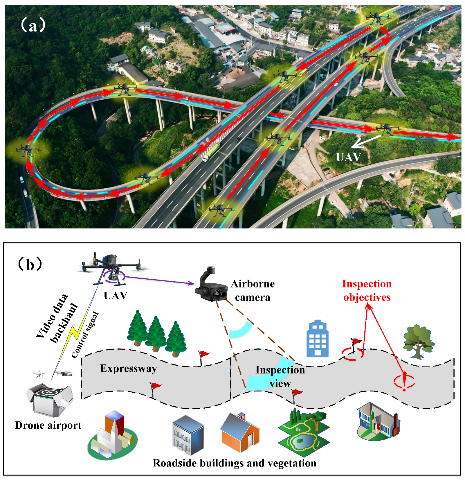
2. System Model and Problem Formulation

In this section, we first introduce the model of using UAV for highway inspection, and then summarize the drone inspection planning issues that need to be optimized.

2.1. System Model

Using UAVs based on automated airports to patrol the highway environment can greatly reduce the cost of manual inspection processes, and due to their broad field of vision (see Figure 1), their inspection effectiveness is more advantageous compared to the ground inspection. Thanks to the development of mobile communication systems, the visual content (the inspection data) of the drone’s flight process can be wirelessly transmitted back to the unmanned airport and the management platform behind it. Therefore, multiple inspection targets on highways must be covered during drone flight, and in order to ensure inspection quality, the signal transmission quality of the UAV needs to be guaranteed in order to meet the clarity requirements of returning video and other data. The field of view of UAV mounted camera should be able to cover the inspection targets and highway curves well, to ensure that the content of concern can be inspected.
The inspection process of the UAV is set from the starting point S to the destination point D, which includes N inspection targets. Considering the curve characteristics of highways themselves, this paper assumes that the inspection sequence of targets is determined. This setting is reasonable, as for safety reasons, the UAV needs to patrol on the periphery of both sides of the highway, and the order in which the UAV flies through inspection points can be ensured by dividing inspection targets (inspection points) onto both sides of the highway. The total number of inspection sections for the UAV is  N + 1 , and their corresponding interval lengths are represented as  L 0 , L 1 , , L N . For convenience, this paper sets the flight altitude of the UAV to be fixed within each inspection section. The flying heights corresponding to multiple inspection sections are represented as  h 0 , h 1 , , h N . Without loss of generality, this paper sets each patrol target in the expressway scene as a circle, and their space radii are expressed as  r 1 , r 2 , , r N . The UAV takes photos or records the inspection targets by hovering around them, and the hovering time for each inspection target is represented as  t 1 , t 2 , , t N . The hovering heights of the UAV for inspection of each target are  h 1 H , h 2 H , h N H .
To ensure the spatial integrity of the UAV’s onboard camera for the inspection section and inspection target, the minimum flight altitude of the UAV can be calculated as  h min = f × r R C C D , where f represents the focal length of the airborne camera,  R C C D  denotes the lens radius size of the airborne camera equivalent to the CCD camera, and r signifies the radius size of the inspection object [30,31].
In highway scenarios, the patrol process of the UAV may frequently encounter non-line of sight (NLOS) transmission of signals, and the probability of line of sight (LOS) transmission of the UAV is expressed as [32]
P L O S = 1 1 + a exp b θ a ,
where  θ = arctan h L , a and b represent parameters related to the transmission environment, h and L represent the flight altitude of the UAV and the distance interval between the UAV’s vertical projection on the ground and the ground signal transceiver, respectively. Correspondingly, the expected received power of the signal of the UAV at its current position is  P ¯ h = P L O S β δ L O S + 1 P L O S β δ N L O S , where  β δ L O S , and  δ N L O S , respectively, represent the transmission power of the signal, the corresponding path loss in LOS environment, and the corresponding path loss in NLOS environment.
Taking into account the starting and ending points, inspection sections, and inspection targets of the UAV, the inspection height of the UAV in the entire highway scene can be summarized as  h S , h 0 , h 1 H , h 1 , h 2 H , h 2 , h N H , h N , h D 2 N + 3 , where  h S  and  h D  denote the altitude of the starting and ending unmanned airports, respectively. And if the starting and ending points are the same unmanned airport, then  h S = h D . For the convenience of representation, this paper re-expresses the sequence as  τ 0 , τ 1 , τ 2 , τ M , with  M = 2 N + 2 .
For the rotorcraft drone, its power consumption during the hovering process can be expressed as [33,34]
P h = δ 8 ρ s A Ω 3 R 3 + ( 1 + χ ) W 3 / 2 2 ρ A ,
where  δ  denotes the profile drag coefficient,  ρ  represents air density, while A, s, R Ω χ  and W, respectively, signify rotor disc area, rotor solidity, rotor radius, blade angular velocity, incremental correction factor to induced power and aircraft weight. The power consumption of the UAV during flight is expressed as
P ( V ) = P 0 1 + 3 V 2 U tip 2 + P i 1 + V 4 4 v 0 4 V 2 2 v 0 2 1 / 2 + 1 2 d 0 ρ s A V 3 ,
in which  P 0  and  P i  correspond to the first and second terms in Equation (2), respectively. V represents the flight speed of the UAV,  U tip  represents the speed of the rotor blades,  v 0  represents the average rotor speed generated during hovering, and  d 0  represents the fuselage drag ratio. Furthermore, the power consumption of the UAV during ascent and descent can be written as
P ( V , κ ˜ ) = P 0 1 + 3 V 2 Ω 2 R 2 + P i κ ˜ κ ˜ 2 + V 4 4 v 0 4 V 2 2 v 0 2 1 / 2 + 1 2 d 0 ρ s A V 3 ,
where  κ ˜  represents the thrust to weight ratio, we have  κ ˜ > 1  when the UAV rises, otherwise  κ ˜ < 1  when the UAV descends. For simplicity, this paper sets the speed of the UAV’s ascent and descent processes to be constant at  V U D , and the thrust to weight ratio is fixed at  κ ˜ U  and  κ ˜ D , respectively. Therefore, the power consumption of the corresponding processes can be expressed as  P ( V U D , κ ˜ U )  and  P ( V U D , κ ˜ D ) .

2.2. Problem Formulation

The effectiveness of the UAV inspection process is crucial. By referring to the minimum flight altitude of the UAV, this pair sets the inspection effect coefficient as  e h min / h x 1  with e denoting the Euler number and  h x  representing the current flight altitude of the UAV.
Let  Ψ  represent the overall effect of the inspection process, which can be calculated using the following equation:
Ψ = i = 0 N e h min / h i 1 × L i + j = 1 N e h min / h j H 1 × M j ,
in which  M j , j = 1 , 2 , , N  represents the importance of the j-th inspection target.
Due to the relatively small communication power of UAVs compared to flight power consumption, this paper ignores the former and aims to optimize the inspection effect for highway scenarios. With the available energy of the UAV supporting the inspection process, inspection altitude and speed, as well as signal transmission quality as constraints, the optimization problem of UAV inspection process can be summarized as follows:
max h i , h j H , v i f , i = 0 , 1 , , N , j = 1 , 2 , , N Ψ s . t . k = 0 M 1 τ k + 1 τ k × P ( V U D , κ ˜ U ) o r P ( V U D , κ ˜ D ) × τ k + 1 τ k V U D +
i = 0 N P ( v i f ) × L i v i f + i = 1 N P h × t i E
1 2 N + 1 i = 0 N P ¯ h i + i = 0 N + 1 P ¯ h i H Φ
f × r w a y R C C D h i h max , i = 0 , 1 , N
f × r i R C C D h i H h max , i = 1 , 2 , N
0 v i f v max , i = 0 , 1 , N ,
where  r w a y  represents the equivalent radius of the highway,  h max  represents the upper limit of the UAV’s cruising altitude,  v max  represents the upper limit of the UAV’s cruising speed, and  Φ  represents the threshold requirement for the expected average received power of the UAV’s signal.
We can observe that problem (6) belongs to a mixed integer nonlinear programming problem. This paper will propose an effective heuristic method in the next section to improve the effectiveness of planning.

3. Proposed Path Planning Method

In this section, we first provide a method for supplementing the cruise points of the unmanned aerial vehicle, and then introduce the proposed drone inspection planning for highways (DIPH) method.

3.1. Selection of Supplementary Inspection Points

We have noticed that the density of patrol points can greatly affect the quality of drone inspections on highways, as (1) the highway management department does not recommend drones to fly directly over highways, but rather over both sides of the road to prevent drones from falling to the ground and posing risks to the operation of highways; (2) if the drone’s patrol points are too sparse, the drone’s straight-line flight between points will significantly affect the correlation between the camera mounted on it and the highway road surface. Therefore, we first briefly provide a method for selecting patrol points for highways before introducing the unmanned aerial vehicle path planning method proposed in this paper.
As a feasible method, we believe that the acquisition of patrol points can be briefly divided into four steps, i.e., data acquisition, center point selection, side delineation and patrol points selection. We now introduce these four steps separately.

3.1.1. Data Acquisition

In order to obtain the patrol points of the highway area, it is first necessary to obtain the longitude and latitude information of the area. Generally, this information can be obtained from geographic information system (GIS) data. Figure 2a illustrates the longitude and latitude value points of Guiyang section of the highway (Guizhou Province, China).

3.1.2. Center Point Selection

The goal of this method is to obtain dense points on both sides of the highway as patrol points for UAVs. Therefore, we divide the focus area into multiple sub-road sections based on the range of longitude and latitude values, and obtain the center of each sub-road section by averaging the longitude and latitude values (see Figure 2b). Note that the selected density of sub-road sections corresponds to the density of patrol points. By relying on these selected centers, we can further divide the edges and select inspection points.

3.1.3. Side Delineation

For the deployment of a single automatic airport on a highway, the drone’s patrol process needs to cover both sides of the highway, and this inspection perspective and content are more diverse compared to unilateral inspections on highways. On this condition, the selection of patrol points needs to be on both sides of the highway, and we then divide the sub-section into two parts based on the latitude of the points in the sub-section compared to the latitude of the center point (see Figure 2b).

3.1.4. Patrol Points Selection

In this step, we select one point on each side of each sub-section as the patrol point. Since each sub-section is divided into two parts, we only need to select one point located at the edge of the highway in each part. For simplicity, we select the point farthest from the center point in each part as the patrol point (see Figure 2c,d).
By performing the above four steps and finally sorting all selected patrol points by the highway side, we can obtain the drone’s patrol points, which are spatially fitted to the highway curve. It should be noted that the patrol points in this section are not completely equivalent to the patrol target points mentioned earlier. The patrol target points can be integrated into the drone’s patrol points, such as by replacing some close points in the patrol points or directly adding them to the set of patrol points. For the convenience of understanding, we use patrol points as a general term in the following text, which includes the target points to be inspected and the path points to improve the effectiveness of drone patrols, considering that patrol points can also be considered as inspection target points.

3.2. Summary of the Proposed DIPH Method

3.2.1. Method Preliminary

We notice that the solution to problem (6) includes three types of parameters, namely, the hovering heights of the drone facing the inspection targets, the patrol heights of the drone between the inspection targets, and the patrol speeds. Additionally, through observation, we can find that the goal of the problem is to maximize the effectiveness of cruising, while the cruising speed of drones is only a parameter of the energy consumption condition (i.e., (6b)). Therefore, by referring to Equation (3), the speed of cruising can be calculated from the perspective of minimizing energy consumption, and this speed has the least impact on the energy consumption condition.
Regarding the cruising altitude of the UAV between cruising points, this paper sets the flight altitude of the UAV to be consistent within each segment, considering that the selection of patrol points has already matched the highway curve and the distance between adjacent patrol points is short. The selection of UAV patrol altitude and the selection of UAV suspension altitude towards patrol targets have similarities in ideas. Both of which have the same relationship with patrol effectiveness, signal quality, and the energy consumption. By referring to Equation (1), it can be observed that the higher the flying (hovering) altitude of the UAV, the greater the probability of LOS in the communication link between the UAV and the airport. Specifically, as the flight altitude increases, the strength of the communication signal first increases and then decreases. However, the flight altitude of the drone used in this paper cannot reach the altitude corresponding to the maximum communication signal strength (see Figure 6 in [32]). In other words, we can assume that the higher the flight altitude of the drone, the stronger its communication signal strength, and we can obtain the flight altitude that matches the signal strength through one-dimensional search.
Considering that the UAV inspection process needs to meet the requirements of inspection field of view quality, and the higher the drone’s flight altitude, the greater the energy consumed during its ascent, the preliminary selected drone inspection (hovering) altitude in this paper corresponds to the higher values of the altitude corresponding to the inspection field of view quality and the signal strength threshold corresponding to the altitude. At this point, we can preliminarily obtain solutions for three types of parameters. Considering that the currently selected parameters may not meet condition (6b), this paper reduces the energy consumption of the UAV by smoothing out the differences between the cruising heights of the UAV on certain road sections and the hovering heights of adjacent cruising points.

3.2.2. Method Summary

We summarize the proposed DIPH method and its process in Algorithm 1 and Figure 3, respectively. In the method, we first calculate the hovering height of the corresponding drone for each inspection target, combined with the transmission requirements of signal quality. Meanwhile, considering the requirements for inspection quality, we obtain the suspension height of the drone by taking a larger value in Step 5. We then determine whether each obtained drone’s hovering height exceeds the drone’s ceiling, and if so, it is determined that a feasible solution to the parameters cannot be obtained.    
Algorithm 1: The drone inspection planning for highways (DIPH) method.
    1:
Input δ ρ , A, s, R Ω χ , W d 0 v 0 U tip V U D κ ˜ U κ ˜ D a , b R C C D , L 0 , L 1 , , L N , f ,
r 1 , r 2 , , r N , t 1 , t 2 , , t N β M j , j = 1 , 2 , , N .
    2:
Output h i , h j H , v i f , i = 0 , 1 , , N , j = 1 , 2 , , N .
    3:
Initialize r w a y h m a x v m a x Φ .
                                                           
    4:
Let  P ¯ h i H = Φ i = 1 , 2 , , N , and obtain  h i , 1 H  by using the dichotomy algorithm.
    5:
Calculate  h i , 2 H = max h i , 1 H , f × r i R C C D i = 1 , 2 , , N .
    6:
If  i h i , 2 H > h max i = 1 , 2 , , N  Do
    7:
      Break, there is no feasible solution.
    8:
Else
    9:
      Let  P ¯ h i = Φ i = 0 , 1 , , N , and obtain  h i , 1  by using the dichotomy algorithm.
  10:
      Calculate  h i , 2 = max h i , 1 , f × r w a y R C C D .
  11:
      If  i h i , 2 > h max i = 0 , 1 , , N  Do
  12:
              Break, there is no feasible solution.
  13:
      Else
  14:
              Combine (3) and use the dichotomy method to obtain  v = min P V , and
                  set  v i f = v , i = 0 , 1 , , N .
  15:
              If  v i f , h i , 2 H , h i , 2  satisfy (6b) Do
  16:
                     Output  v i f , h i , 2 H , h i , 2 .
  17:
              Else
  18:
                     Search for  max i h i , 2 h i 1 , 2 H  in the current results, and let
                          h i , 2 = h i 1 , 2 H = max h i , 2 , h i 1 , 2 H .
  19:
                     Perform Step 15.
  20:
              End If
  21:
      End If
  22:
End If
Next, we calculate the cruising altitude of the drone on each road section (corresponding to the road section between adjacent inspection points) through a process similar to the above, and make conditional judgments on the obtained altitudes. Considering that the cruising energy consumption of drones decreases first and then increases with their flight speed, this paper uses the dichotomy method to obtain the cruising speed corresponding to the minimum energy consumption during the drone cruising process.
Finally, based on obtaining three types of parameters to be solved, this paper evaluates the availability of the parameters in Step 15. If the parameters cannot meet condition (6b), we search to find the maximum difference in height between the adjacent patrol section and patrol point, and reduce the energy consumption of the drone by making the two heights equal (take the larger of the two). The height adjustment and condition judgment loop execution until the parameters meet condition (6b).

3.2.3. Complexity Analysis

We now analyze the complexity of the proposed DIPH method. We assume that the number of optional heights and speeds for the UAV is  Λ  and  Υ  discrete values, respectively. Then, the complexity of Steps 4, 9 and 14 is  O ( log 2 Λ ) O ( log 2 Λ ) , and  O ( log 2 Υ ) , respectively. Additionally, the complexity of Steps 5, 6, 10 and 11 is  O ( N ) . The complexity of the loop from Steps 18 to 19 is  O ( ϖ N )  with  ϖ  denoting the number of times the loop is executed. Therefore, the complexity of the DIPH method proposed in this paper can be expressed as  O ( 4 N + ϖ N + 2 log 2 Λ + log 2 Υ ) . Considering that  ϖ  is almost zero in the simulation and we have  N > Λ , N > Υ , the complexity can be further simplified as  O ( N ) .

4. Simulation and Performance Analysis

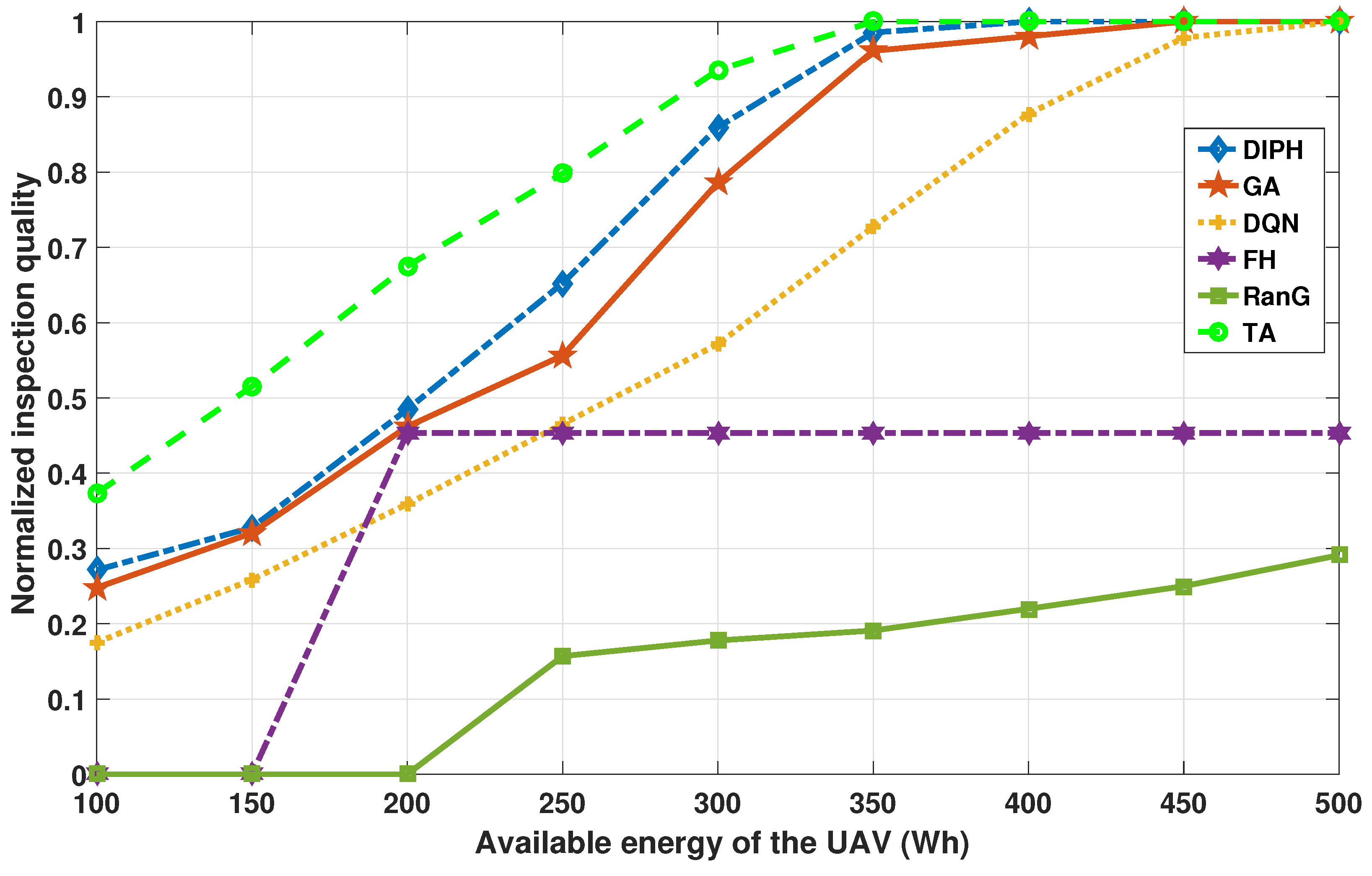
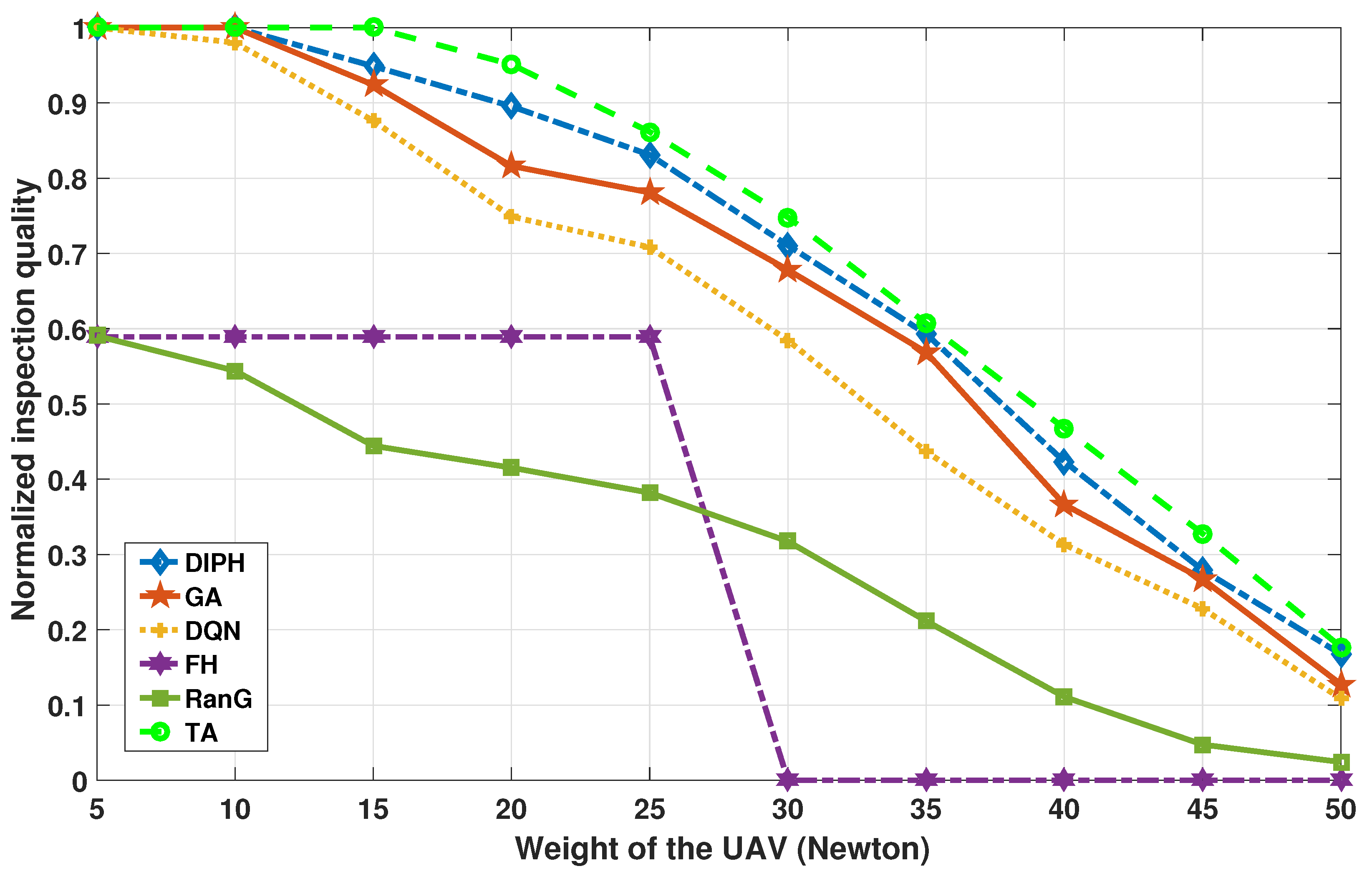
4.1. Simulation Settings

To verify the effectiveness of the method proposed in this paper, we generate a rectangle 5 km long and 30 m wide to simulate a highway, and generate 20 to 200 patrol points using the method in Section 3.1, where 20% of the patrol points are considered as inspection targets for the UAV. This paper sets the drone’s hovering observation time for patrol points to be randomly generated with equal probability between 0 and 30 s. The transmission bandwidth and power of the drone’s return data are set to 20 MHz and 20 dBm, respectively, while the threshold requirement for the expected average received power of the UAV’s signal  Φ  is set as −160 dBm/Hz. The fuselage drag ratio  d 0 , average rotor speed  v 0 , speed of the rotor blades  U tip , profile drag coefficient  δ , air density  ρ , rotor solidity s, rotor disc area A, rotor radius R, blade angular velocity  Ω , incremental correction factor to induced power  χ  are, respectively, set as 0.6, 1.44∼7.19, 48 m/s, 0.012, 1.225 kg/m 3 , 0.05, 0.79 m 2 , 0.12 m, 400 rads/s and 0.1. We randomly generate the importance coefficient of the inspection target (i.e.,  M j ) between 1 and 100.
To demonstrate the performance of the proposed method under parameter changes, we set the weight variation range of the as 5 to 50 Newton, while the available energy of the UAV is set to 100∼500 Wh. Parameters related to the transmission environment (i.e., a and b) are set as 0.5 and 1.2, respectively. Meanwhile, the focal length of the airborne camera f and the lens radius size of the airborne camera equivalent to the CCD camera  R C C D  are separately set as 105 mm and 25 mm. The simulation parameters are summarized in Table 1, and all simulations are carried out in Matlab R2016a on a PC with Windows 10 and an Intel i7-12700 CPU. The results shown in this paper are averaged over 200 trials.
To comprehensively demonstrate the path planning efficiency and planning effectiveness of the proposed DIPH method, the following five additional methods are adopted for performance comparison:
  • GA, the genetic algorithm [11], in the simulation, we set the three parameters of cruising altitude, cruising speed, and hovering altitude as gene sequences and solve them with objective (6a) as the optimization value.
  • DQN, method based on deep Q-network [25], this paper takes the parameters of the UAV and patrol points as the state inputs of the method, and takes the patrol altitude, patrol speed, and hovering altitude as the model’s actions step by step. The model is trained with the patrol quality as the reward.
  • FH, the DIPH method with fixed height, on the basis of using the DIPH method to obtain the various cruising heights and hovering heights of the UAV, this method directly takes the maximum value of all heights as the cruising and hovering heights.
  • RanG, method of randomly generating relevant parameters, this method randomly generates the three types of parameters for the UAV within the feasible range.
  • TA, the traversal method, this method determines all possible combination solutions through traversal, and selects the solution that can achieve target (6a) as the output of the method.

4.2. Performance and Analysis

We first verify the energy consumption of the drone and the quality of the patrol process under different patrol points using the method proposed in this paper. Figure 4 shows the results. We set  W =  10 Newton,  E =  400 Wh, and the number of inspection targets and corresponding inspection time are fixed in the current simulation. For ease of presentation, we have normalized the two performance values. As can be seen, the energy consumption and inspection effectiveness of the UAV gradually improve with the increase in inspection points. This is because the increase in the number of patrol points means that there are more adjustments to the cruising altitude of the drone, which requires additional energy consumption. However, this adjustment process is beneficial for improving the cruising quality of the drone, as the patrol route that matches the shape of the highway and the patrol height that matches the highway section can improve the inspection effect in terms of inspection field of view and return signal quality.
Secondly, the planning performance of each comparison method under different number of patrol points is shown in Figure 5. We set  W =  10 Newton and  E =  500 Wh, which ensures that the energy required for the drone inspection process is sufficient. The number of inspection targets and corresponding inspection time are fixed in the current simulation. We can observe that all six methods increase with the number of patrol points, which is attributed to the gradual improvement of shooting results achieved by drone mounted camera. GA and DQN methods have some interleaving in performance, but overall, GA performs better than DQN. The TA method performs best among all methods because it compares all possible solutions. Compared to the highly complex TA method, although there is a significant gap, the DIPH method proposed in this paper has better performance than the other four methods.
We then compare and verify the performance of six methods under the condition of changes in available energy of the UAV, and the results are shown in Figure 6. We set  W =  10 Newton, and the number of patrol points is set as 50. The number of inspection targets and corresponding inspection time are fixed in the current simulation. A value of 0 for inspection quality means that the current method cannot obtain a valid solution. It can be seen that when the available energy of the UAV is low, FH method and RanG method cannot obtain feasible solutions, this is because the flight altitude of the FH method is too high, making the required energy higher than the available energy of the drone, while the RanG method cannot obtain a feasible solution under harsh conditions due to the randomness of solution selection. An interesting phenomenon can be seen from Figure 6, which is that when the energy of the UAV exceeds 200 Wh, the FH method is feasible, and as the energy increases, the inspection effect of this method remains fixed. This is because the results of the FH method do not change with the energy of the UAV, and the output solution is a fixed value. Meanwhile, we can conclude from the figure that the overall ranking of the performance of the six methods is successively TA, DIPH, GA, DQN, FH and RanG.
Fourthly, we validate the performance of the methods in response to changes in drone weight, and the results are illustrated in Figure 7. We set  E =  400 Wh, and the number of patrol points is set as 60. The number of inspection targets and corresponding inspection time are fixed in the current simulation. It can be observed that except for the FH method with special characteristics, the inspection quality of other methods gradually decreases with the increase in UAV weight. Due to the fact that the fixed flight altitude selected by the FH method does not change with the weight of the drone, the inspection quality of this method remains constant during the initial increase in UAV weight, and in the later stages of increase, the planning becomes ineffective due to insufficient available energy. Among the remaining five methods, the DIPH method proposed in this paper is second only to the TA method in terms of performance, and sequentially superior to GA, DQN, and RanG methods.
We finally summarize the time consumption of each method in Table 2. It should be noted that the DQN method requires pre-training of the model, therefore it requires training time. Although the training process can be carried out before the DQN method is applied, compared to methods that do not require training, this time cannot be directly ignored. From the table, we can see that among the six methods, the TA method takes the longest time, surpassing the DIPH method by 5000 times, and this is unacceptable in certain situations (such as the need to dispatch the UAV for emergency patrols in a timely manner). The average time spent on DIPH, GA, FH, and RanG is 15.7 ms, 2168.2 ms, 10.5 ms, and 1.2 ms, respectively. It can be considered that the DIPH method does not have disadvantages compared to other methods in terms of computational efficiency.

4.3. Discussion

In order to clearly observe the performance of the methods, this paper sorts and summarizes the performance of the methods in Table 3. Due to the long training time required, the DQN method is not taken into account in the efficiency entry therein. It can be seen that the DIPH proposed in this paper ranks third in terms of operational efficiency, and its performance in other aspects is only second to the TA method which has very low operational efficiency and cannot be used in practical scenarios. Taking into account the overall performance (i.e., inspection quality and execution efficiency) of methods, we can conclude that the DIPH method proposed in this paper has better performance compared to other methods.

5. Conclusions

This paper considered the path planning problem of unmanned aerial vehicles for highway scenarios. In response to the mismatch between the drone patrol path and the shape of the highway, as well as the urgent need to improve the quality of drone inspection, this paper proposed an efficient path planning method for the unmanned aerial vehicle, aiming to improve the quality of the UAV inspection process by quickly setting parameters including the UAV’s inspection altitudes, suspension altitudes towards inspection targets, and inspection speeds. The simulation results with multiple feasible comparison methods indicate that the proposed method has advantages in terms of overall performance of operational efficiency and planning effectiveness.

Author Contributions

Conceptualization, Y.L. and P.Z.; investigation, S.G. and X.L.; methodology, P.Z. and X.L.; project administration, P.Z. and H.L.; validation, S.G., Y.L. and H.L.; writing—original draft, Y.L. and P.Z.; writing—review and editing, S.G. and X.L. All authors have read and agreed to the published version of the manuscript.

Funding

This work was supported in part by 2023 Guizhou Provincial Science and Technology Support Plan Project (No. 282), in part by the Fundamental Research Funds for the Central Universities (No. 328202206, No. 328202232 and No. 3282023034), the Beijing Natural Science Foundation (No. L192002), and in part by the “Advanced and sophisticated” discipline construction project of universities in Beijing (No. 20210013Z0401), the China National Key R&D Program (No. 2020YF-B1808000).

Data Availability Statement

Not applicable.

Conflicts of Interest

The authors declare no conflict of interest.

Abbreviations

The following abbreviations are used in this manuscript:
IoTInternet of Things
DRLdeep reinforcement learning
DQNdeep Q-Network
UAVunmanned aerial vehicle
AIartificial intelligence
LOSline of sight
NLOSnon line of sight
DIPHdrone inspection planning for highways
GISgeographic information system
PSOparticle swarm optimization
GAgenetic algorithm
LSTMlong short-term memory
CNNconvolutional neural networks

References

  1. McEnroe, P.; Wang, S.; Liyanage, M. A Survey on the Convergence of Edge Computing and AI for UAVs: Opportunities and Challenges. IEEE Internet Things J. 2022, 9, 15435–15459. [Google Scholar] [CrossRef]
  2. Lyu, M.; Zhao, Y.; Huang, C.; Huang, H. Unmanned Aerial Vehicles for Search and Rescue: A Survey. Remote Sens. 2023, 15, 3266. [Google Scholar] [CrossRef]
  3. Mugnai, M.; Teppati Losé, M.; Herrera-Alarcón, E.P.; Baris, G.; Satler, M.; Avizzano, C.A. An Efficient Framework for Autonomous UAV Missions in Partially-Unknown GNSS-Denied Environments. Drones 2023, 7, 471. [Google Scholar] [CrossRef]
  4. Zhou, Y.; Rao, B.; Wang, W. UAV Swarm Intelligence: Recent Advances and Future Trends. IEEE Access 2020, 8, 183856–183878. [Google Scholar] [CrossRef]
  5. Motlagh, N.H.; Bagaa, M.; Taleb, T. Energy and Delay Aware Task Assignment Mechanism for UAV-Based IoT Platform. IEEE Internet Things J. 2019, 6, 6523–6536. [Google Scholar] [CrossRef]
  6. Zhao, Y.; Yan, L.; Dai, J.; Hu, X.; Wei, P.; Xie, H. Robust Planning System for Fast Autonomous Flight in Complex Unknown Environment Using Sparse Directed Frontier Points. Drones 2023, 7, 219. [Google Scholar] [CrossRef]
  7. Baek, D.; Chen, Y.; Bocca, A.; Bottaccioli, L.; Di Cataldo, S.; Gatteschi, V.; Pagliari, D.J.; Patti, E.; Urgese, G.; Chang, N.; et al. Battery-Aware Operation Range Estimation for Terrestrial and Aerial Electric Vehicles. IEEE Trans. Veh. Technol. 2019, 68, 5471–5482. [Google Scholar] [CrossRef]
  8. Piao, S.; Ba, Z.; Su, L.; Koutsonikolas, D.; Li, S.; Ren, K. Automating CSI Measurement with UAVs: From Problem Formulation to Energy-Optimal Solution. In Proceedings of the IEEE INFOCOM 2019—IEEE Conference on Computer Communications, Paris, France, 29 April–2 May 2019; pp. 2404–2412. [Google Scholar] [CrossRef]
  9. Krajewski, R.; Moers, T.; Bock, J.; Vater, L.; Eckstein, L. The rounD Dataset: A Drone Dataset of Road User Trajectories at Roundabouts in Germany. In Proceedings of the 2020 IEEE 23rd International Conference on Intelligent Transportation Systems (ITSC), Rhodes, Greece, 20–23 September 2020; pp. 1–6. [Google Scholar] [CrossRef]
  10. Liu, H.; Chen, Q.; Pan, N.; Sun, Y.; An, Y.; Pan, D. UAV Stocktaking Task-Planning for Industrial Warehouses Based on the Improved Hybrid Differential Evolution Algorithm. IEEE Trans. Ind. Inform. 2022, 18, 582–591. [Google Scholar] [CrossRef]
  11. Shivgan, R.; Dong, Z. Energy-Efficient Drone Coverage Path Planning using Genetic Algorithm. In Proceedings of the 2020 IEEE 21st International Conference on High Performance Switching and Routing (HPSR), Newark, NJ, USA, 11–14 May 2020; pp. 1–6. [Google Scholar] [CrossRef]
  12. Gubán, M.; Udvaros, J. A Path Planning Model with a Genetic Algorithm for Stock Inventory Using a Swarm of Drones. Drones 2022, 6, 364. [Google Scholar] [CrossRef]
  13. Xiong, T.; Liu, F.; Liu, H.; Ge, J.; Li, H.; Ding, K.; Li, Q. Multi-Drone Optimal Mission Assignment and 3D Path Planning for Disaster Rescue. Drones 2023, 7, 394. [Google Scholar] [CrossRef]
  14. Wu, Y.; Wu, S.; Hu, X. Cooperative Path Planning of UAVs & UGVs for a Persistent Surveillance Task in Urban Environments. IEEE Internet Things J. 2021, 8, 4906–4919. [Google Scholar] [CrossRef]
  15. Duan, T.; Wang, W.; Wang, T.; Huang, M.; Zhou, X. A Task Planning Method for UAV Swarm Dynamic Reconstruction Based on a Fourth-Order Motif. Electronics 2023, 12, 692. [Google Scholar] [CrossRef]
  16. Siemiatkowska, B.; Stecz, W. A Framework for Planning and Execution of Drone Swarm Missions in a Hostile Environment. Sensors 2021, 21, 4150. [Google Scholar] [CrossRef] [PubMed]
  17. Kuru, K.; Ansell, D.; Khan, W.; Yetgin, H. Analysis and Optimization of Unmanned Aerial Vehicle Swarms in Logistics: An Intelligent Delivery Platform. IEEE Access 2019, 7, 15804–15831. [Google Scholar] [CrossRef]
  18. Luis, C.E.; Vukosavljev, M.; Schoellig, A.P. Online Trajectory Generation with Distributed Model Predictive Control for Multi-Robot Motion Planning. IEEE Robot. Autom. Lett. 2020, 5, 604–611. [Google Scholar] [CrossRef]
  19. Pant, Y.V.; Abbas, H.; Quaye, R.A.; Mangharam, R. Fly-by-Logic: Control of Multi-Drone Fleets with Temporal Logic Objectives. In Proceedings of the 2018 ACM/IEEE 9th International Conference on Cyber-Physical Systems (ICCPS), Porto, Portugal, 11–13 April 2018; pp. 186–197. [Google Scholar] [CrossRef]
  20. Vasquez-Gomez, J.I.; Herrera-Lozada, J.-C.; Olguin-Carbajal, M. Coverage Path Planning for Surveying Disjoint Areas. In Proceedings of the 2018 International Conference on Unmanned Aircraft Systems (ICUAS), Dallas, TX, USA, 12–15 June 2018; pp. 899–904. [Google Scholar] [CrossRef]
  21. Lee, M.-T.; Chuang, M.-L.; Kuo, S.-T.; Chen, Y.-R. UAV Swarm Real-Time Rerouting by Edge Computing D* Lite Algorithm. Appl. Sci. 2022, 12, 1056. [Google Scholar] [CrossRef]
  22. Zhu, P.; Fang, X. Multi-UAV Cooperative Task Assignment Based on Half Random Q-Learning. Symmetry 2021, 13, 2417. [Google Scholar] [CrossRef]
  23. Piao, C.; Liu, C.H. Energy-Efficient Mobile Crowdsensing by Unmanned Vehicles: A Sequential Deep Reinforcement Learning Approach. IEEE Internet Things J. 2020, 7, 6312–6324. [Google Scholar] [CrossRef]
  24. Tu, G.-T.; Juang, J.-G. UAV Path Planning and Obstacle Avoidance Based on Reinforcement Learning in 3D Environments. Actuators 2023, 12, 57. [Google Scholar] [CrossRef]
  25. Bayerlein, H.; Theile, M.; Caccamo, M.; Gesbert, D. UAV Path Planning for Wireless Data Harvesting: A Deep Reinforcement Learning Approach. In Proceedings of the GLOBECOM 2020—2020 IEEE Global Communications Conference, Taipei, Taiwan, 7–11 December 2020; pp. 1–6. [Google Scholar] [CrossRef]
  26. Maciel-Pearson, B.G.; Akçay, S.; Atapour-Abarghouei, A.; Holder, C.; Breckon, T.P. Multi-Task Regression-Based Learning for Autonomous Unmanned Aerial Vehicle Flight Control Within Unstructured Outdoor Environments. IEEE Robot. Autom. Lett. 2019, 4, 4116–4123. [Google Scholar] [CrossRef]
  27. Majd, A.; Ashraf, A.; Troubitsyna, E.; Daneshtalab, M. Integrating Learning, Optimization, and Prediction for Efficient Navigation of Swarms of Drones. In Proceedings of the 2018 26th Euromicro International Conference on Parallel, Distributed and Network-based Processing (PDP), Cambridge, UK, 21–23 March 2018; pp. 101–108. [Google Scholar] [CrossRef]
  28. Loquercio, A.; Maqueda, A.I.; del-Blanco, C.R.; Scaramuzza, D. DroNet: Learning to Fly by Driving. IEEE Robot. Autom. Lett. 2018, 3, 1088–1095. [Google Scholar] [CrossRef]
  29. Liu, C.H.; Ma, X.; Gao, X.; Tang, J. Distributed Energy-Efficient Multi-UAV Navigation for Long-Term Communication Coverage by Deep Reinforcement Learning. IEEE Trans. Mob. Comput. 2020, 19, 1274–1285. [Google Scholar] [CrossRef]
  30. Benkhoui, Y.; Korchi, T.E.; Reinhold, L. UAS-Based Crack Detection Using Stereo Cameras: A Comparative Study. In Proceedings of the 2019 International Conference on Unmanned Aircraft Systems (ICUAS), Atlanta, GA, USA, 11–14 June 2019; pp. 1031–1035. [Google Scholar] [CrossRef]
  31. Yang, L.; Li, B.; Li, W.; Brand, H.; Jiang, B.; Xiao, J. Concrete defects inspection and 3D mapping using CityFlyer quadrotor robot. IEEE/CAA J. Autom. Sin. 2020, 7, 991–1002. [Google Scholar] [CrossRef]
  32. Al-Hourani, A.; Kandeepan, S.; Lardner, S. Optimal LAP Altitude for Maximum Coverage. IEEE Wirel. Commun. Lett. 2014, 3, 569–572. [Google Scholar] [CrossRef]
  33. Zeng, Y.; Zhang, R. Energy-Efficient UAV Communication With Trajectory Optimization. IEEE Trans. Wirel. Commun. 2017, 16, 3747–3760. [Google Scholar] [CrossRef]
  34. Yang, D.; Wu, Q.; Zeng, Y.; Zhang, R. Energy Tradeoff in Ground-to-UAV Communication via Trajectory Design. IEEE Trans. Veh. Technol. 2018, 67, 6721–6726. [Google Scholar] [CrossRef]
Figure 1. Schematic diagram of UAV inspection process for highway scenes. (a) Patrol trajectory of UAV in highway scenes. (b) System model for UAV inspection on the highway.
Electronics 12 04200 g001
Figure 2. Schematic diagram of the selection process of patrol points for highways. (a) The longitude and latitude value points corresponding to the highway area of concern, this paper takes the Guiyang section of the highway (Guizhou Province, China) as an example. (b) Divide the area into several sub-segments, select the center of each sub-segment, and divide each sub-segment into two sub-regions. (c) Select one point in each sub-segment’s two sub-regions as the patrol point. (d) An enlarged display of part areas of (c).
Electronics 12 04200 g002
Figure 3. Flowchart of the proposed DIPH method.
Electronics 12 04200 g003
Figure 4. Energy consumption and inspection effectiveness of the proposed DIPH method under changes in inspection points.
Electronics 12 04200 g004
Figure 5. Planning performance of various comparison methods under different number of patrol points.
Electronics 12 04200 g005
Figure 6. Performance of the method under the condition of changes in available energy of the UAV.
Electronics 12 04200 g006
Figure 7. The inspection quality of methods under changes in drone weight.
Electronics 12 04200 g007
Table 1. Simulation parameters.
ParameterValue
The width and length of the highway30 m, 5 km
Number of patrol points20∼200
Transmit power of the signal  β 20 dBm (i.e., 100 mW)
The fuselage drag ratio  d 0 0.6
The average rotor speed  v 0 1.44∼7.19
The speed of the rotor blades  U tip 48 m/s
Profile drag coefficient  δ 0.012
Air density  ρ , Rotor solidity s1.225 kg/m 3 , 0.05
Rotor disc area A, Rotor radius R0.79 m 2 , 0.12 m
Blade angular velocity  Ω 400 rads/s
Incremental correction factor to induced power  χ 0.1
Weight of UAV W5∼50 Newton
Available energy of UAV E100∼500 Wh
Φ , Noise power  σ 2 −160 dBm/Hz, −174 dBm/Hz
V U D κ ˜ U κ ˜ D 1 m/s, 1.2, 0.8
a, b,  R C C D , f 0.5, 1.2, 25 mm, 105 mm
r w a y h m a x v m a x 20 m, 1000 m, 30 m/s
  t i , i = 1 , 2 , , N 0∼30 s
  M j , j = 1 , 2 , , N 1∼100
Table 2. Time consumed by methods.
MethodAverage Execution Time
DIPH15.7 ms
GA2168.2 ms
DQN3.6 ms (Average training time: 52,815.1 ms)
FH10.5 ms
RanG1.2 ms
TA89,436.7 ms
Table 3. Summary of methods’ performance.
Performance CategoryPerformance Sorting
Inspection quality vs. Number of inspection pointsTA > DIPH > GA > DQN > FH > RanG
Inspection quality vs. Available energy of the UAVTA > DIPH > GA > DQN > FH > RanG
Inspection quality vs. Weight of the UAVTA > DIPH > GA > DQN > FH ≈ RanG
Operational efficiencyRanG > FH > DIPH ≫ GA ≫ TA
Disclaimer/Publisher’s Note: The statements, opinions and data contained in all publications are solely those of the individual author(s) and contributor(s) and not of MDPI and/or the editor(s). MDPI and/or the editor(s) disclaim responsibility for any injury to people or property resulting from any ideas, methods, instructions or products referred to in the content.

