
Design and Performance Evaluation of a Compact Frequency-Reconfigurable Coplanar-Waveguide-Fed Slotted Patch Antenna for Multi-Band Wireless Communication


Abstract
:1. Introduction
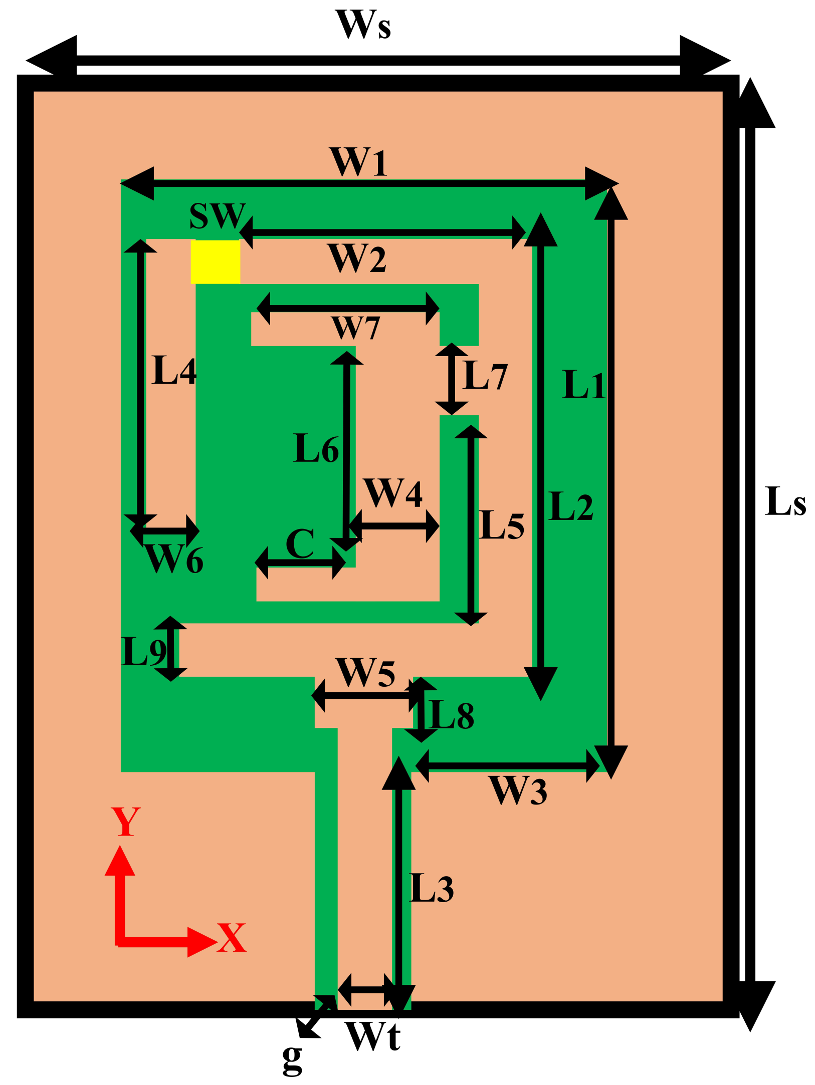
2. Antenna Configuration
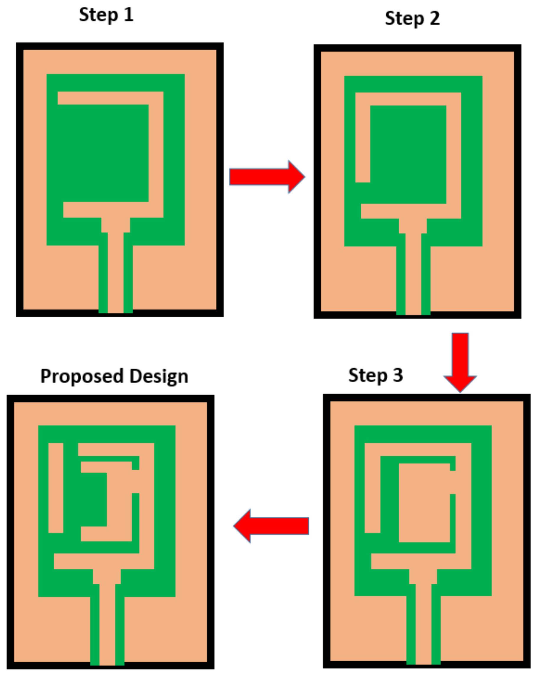
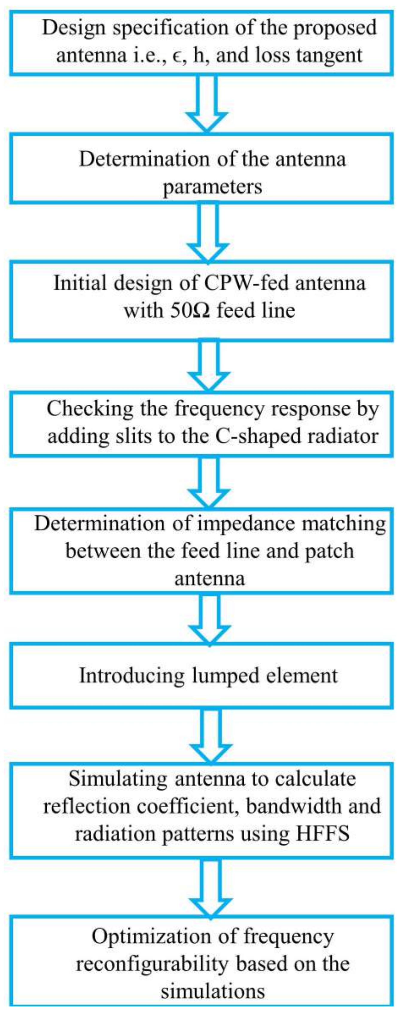
2.1. Design Methodology
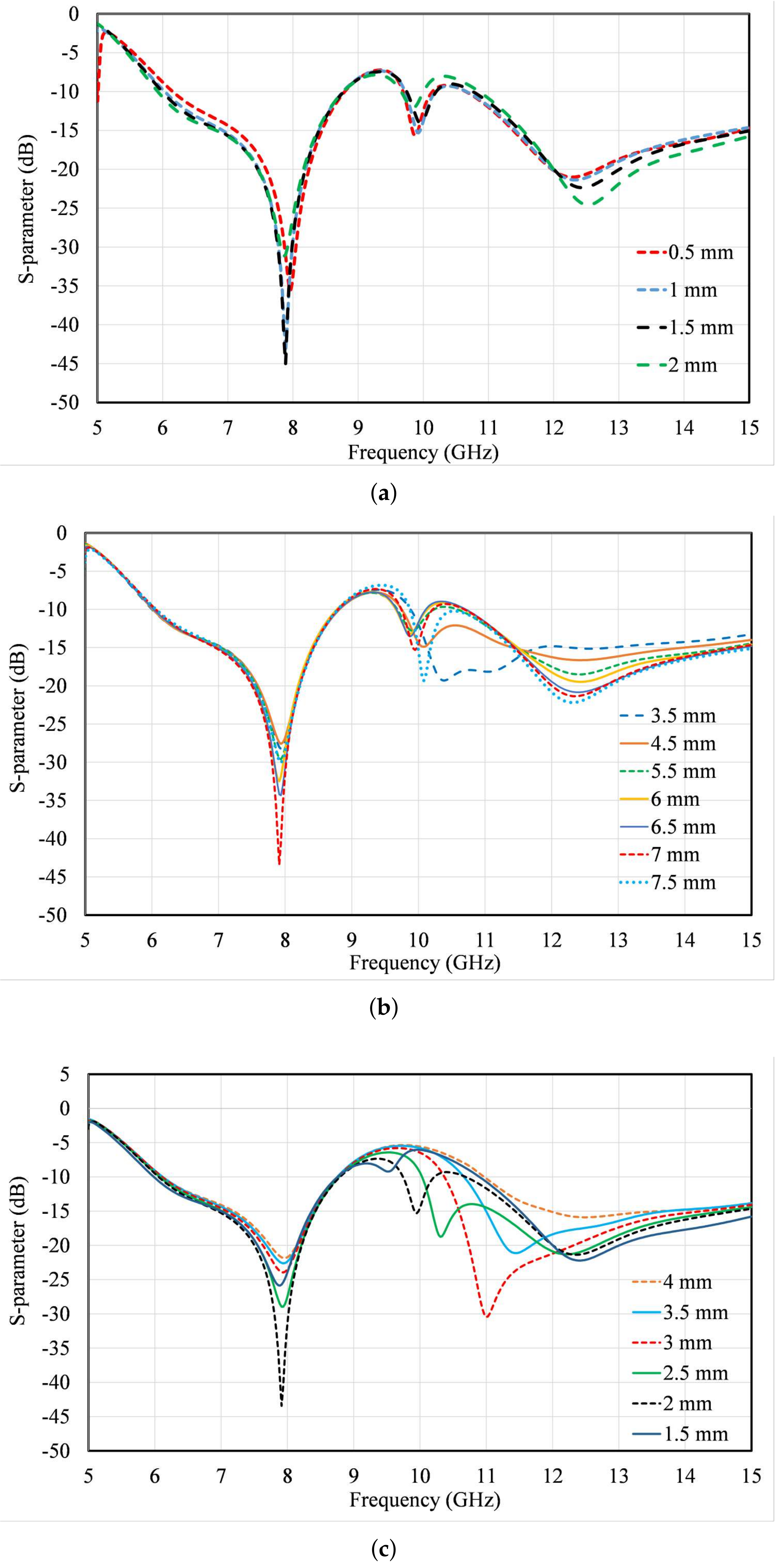
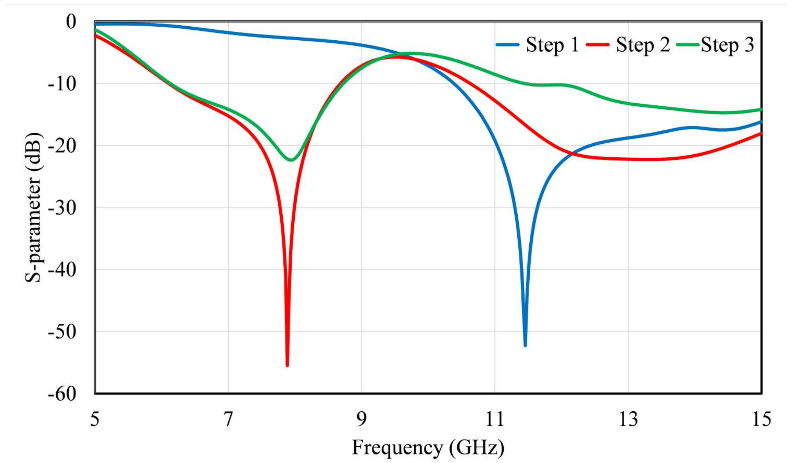
2.2. Parametric Analysis
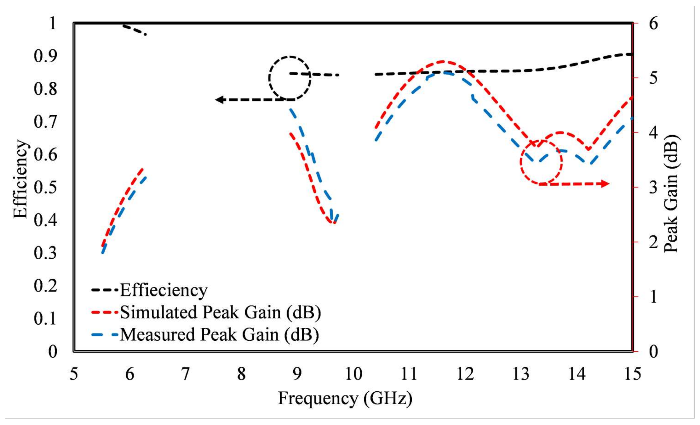
3. Results and Discussion
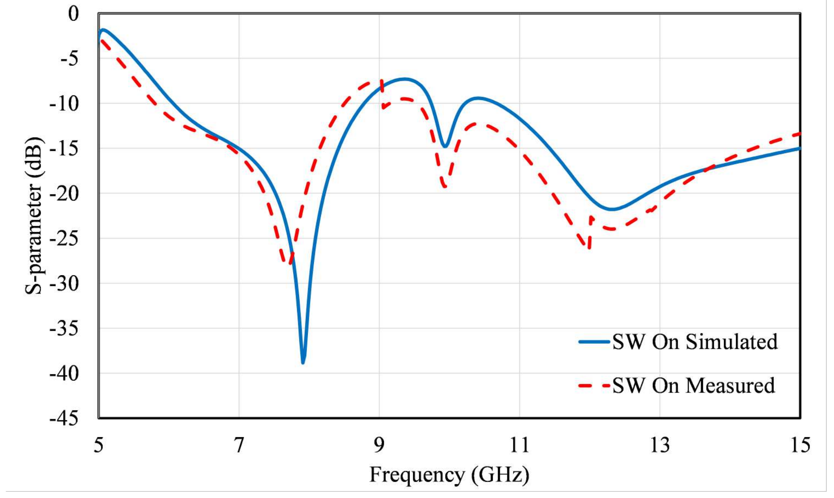
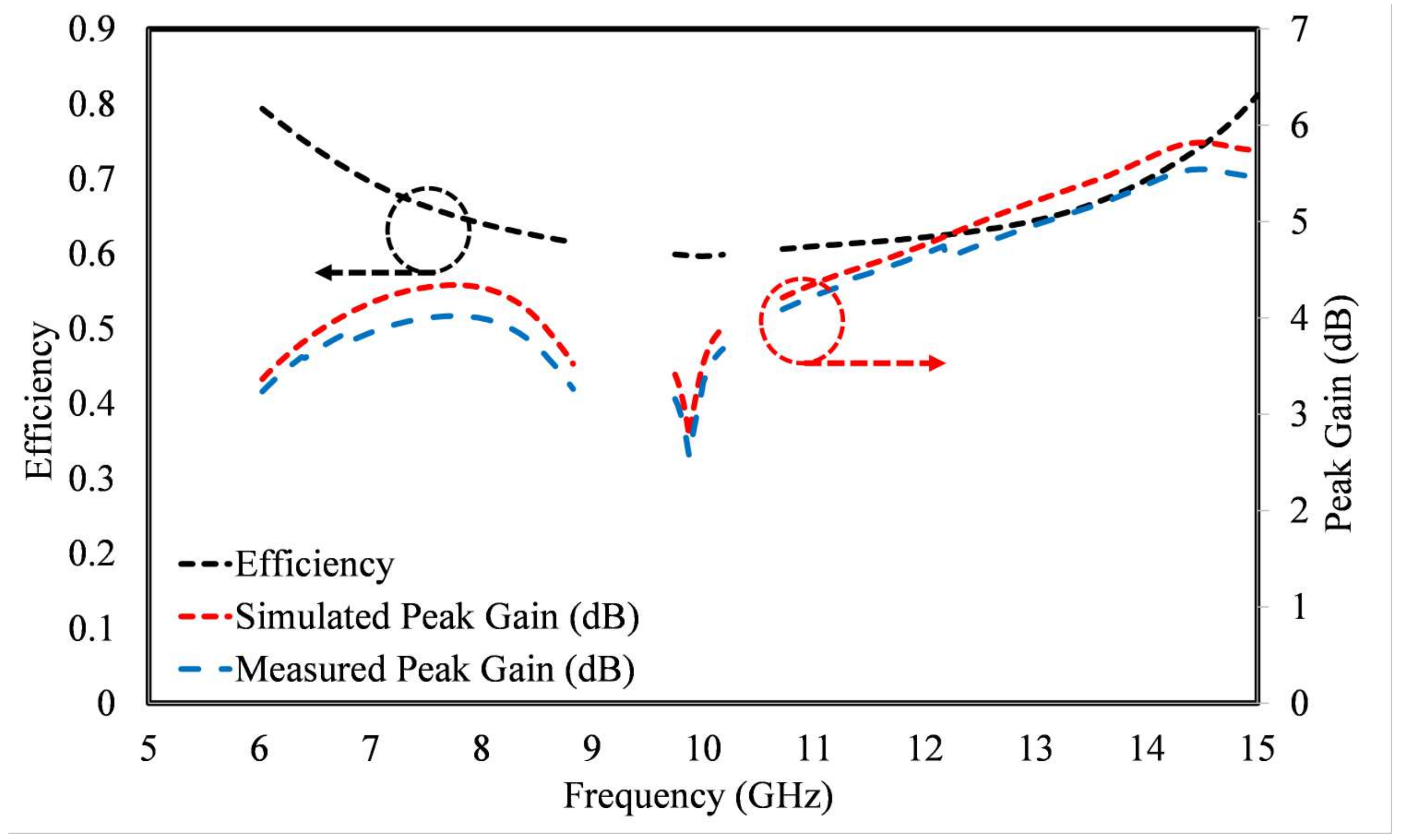
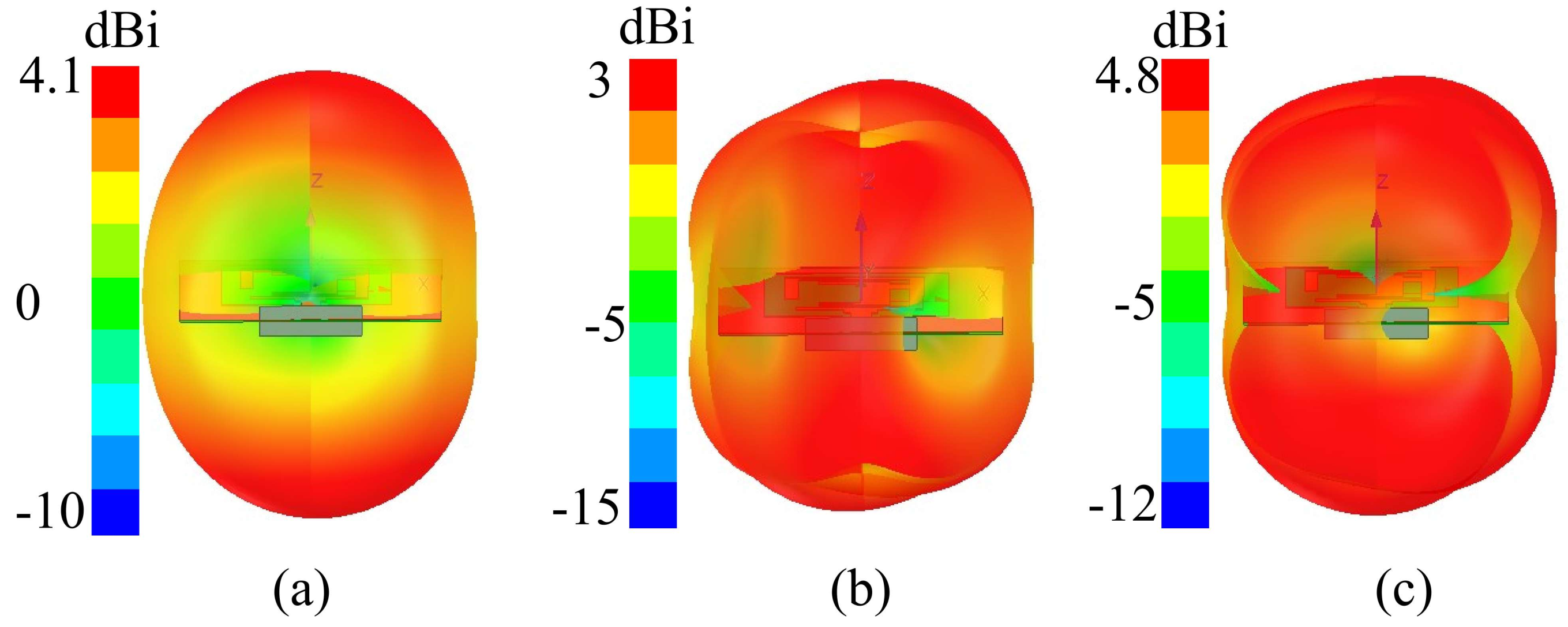
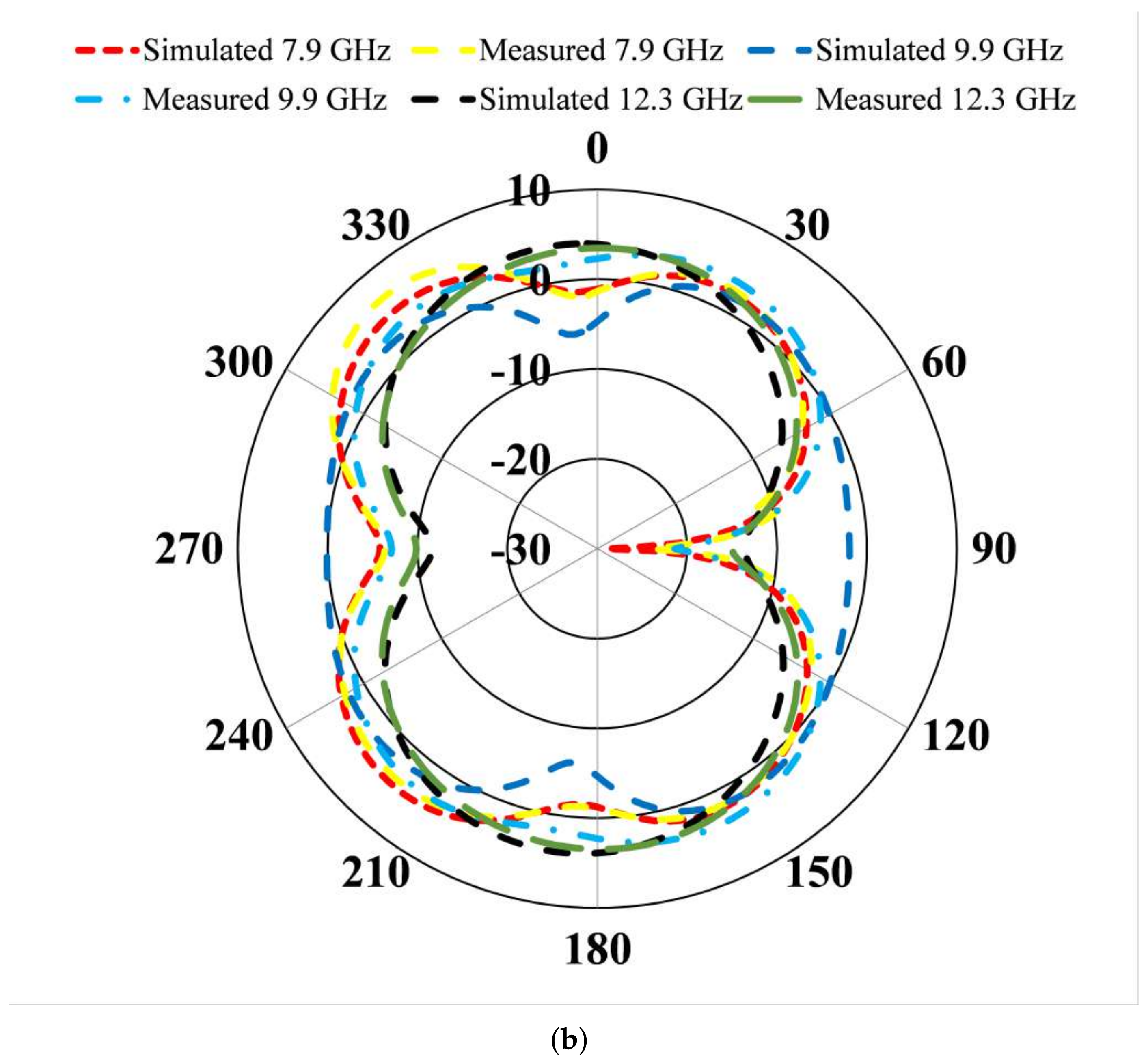
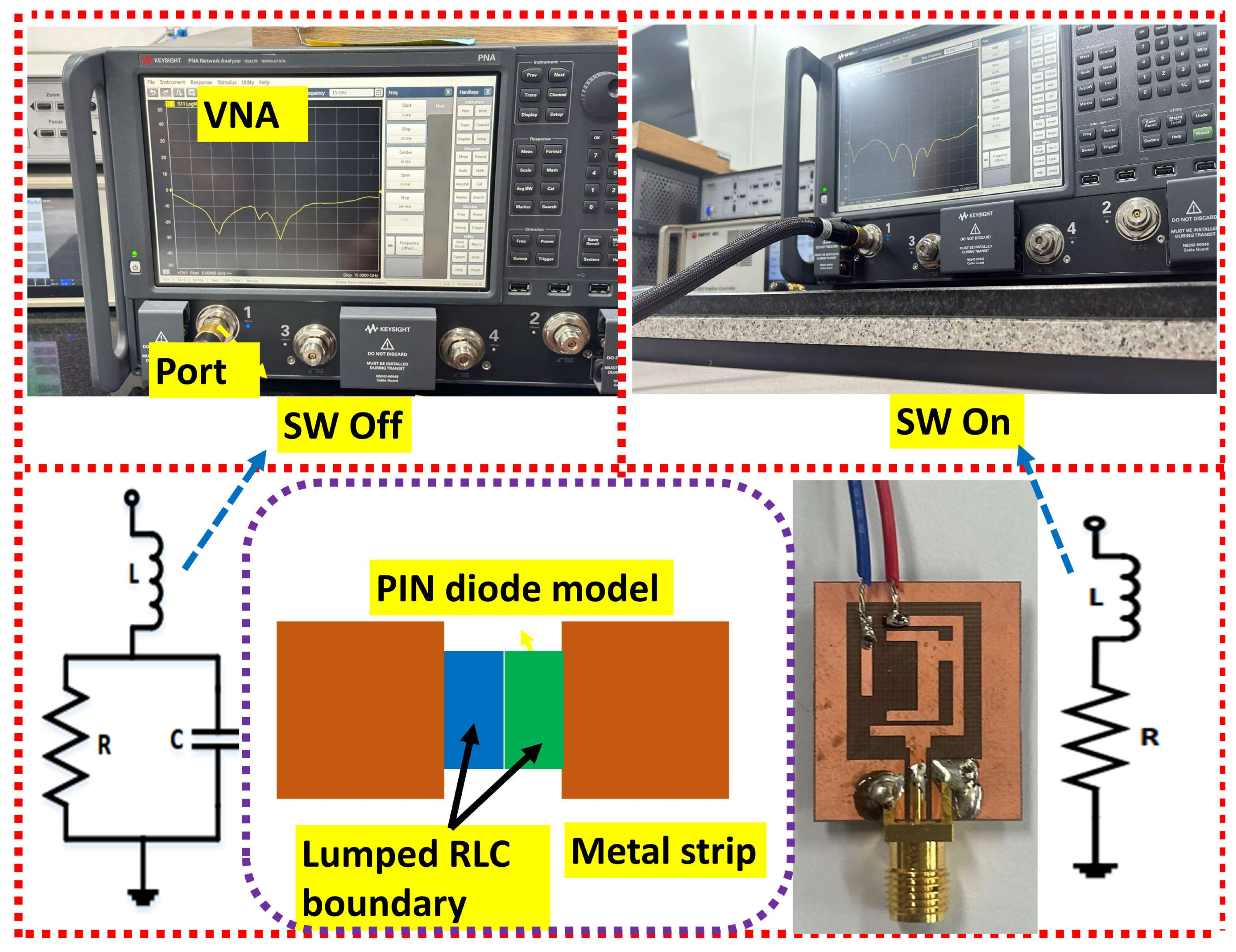
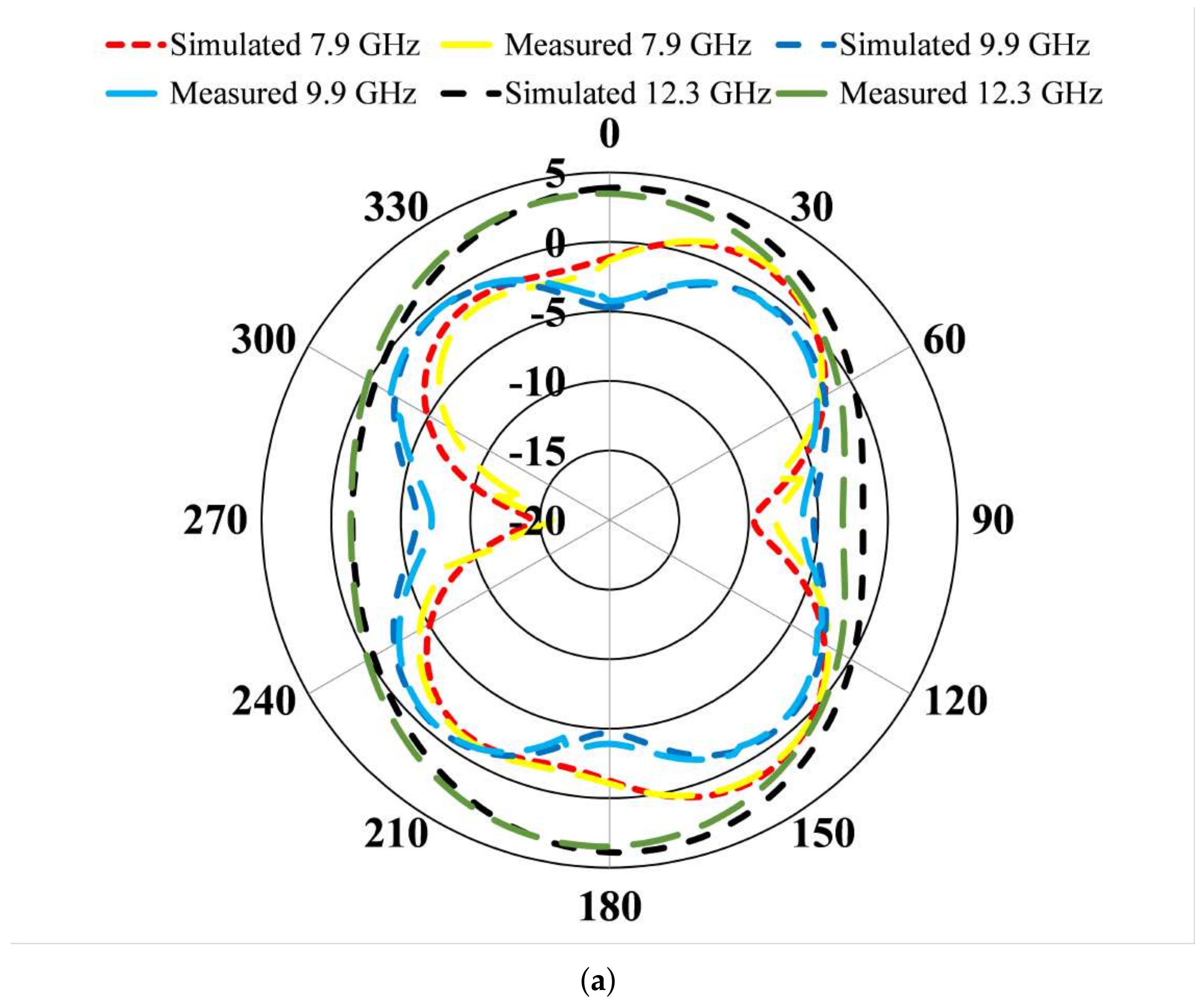
3.1. Switch On
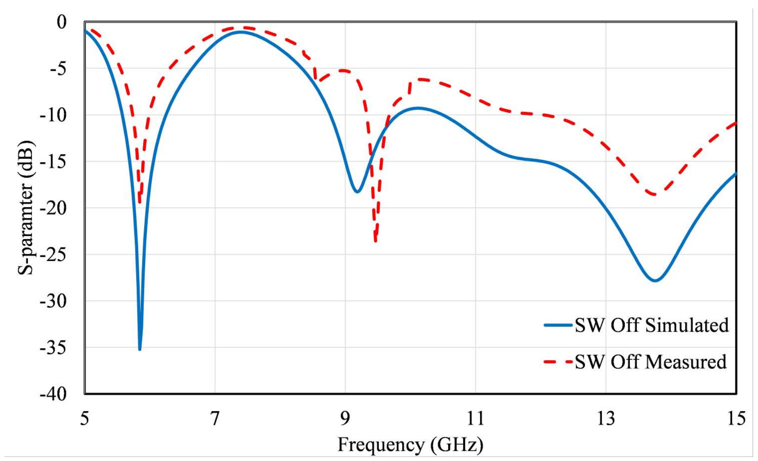
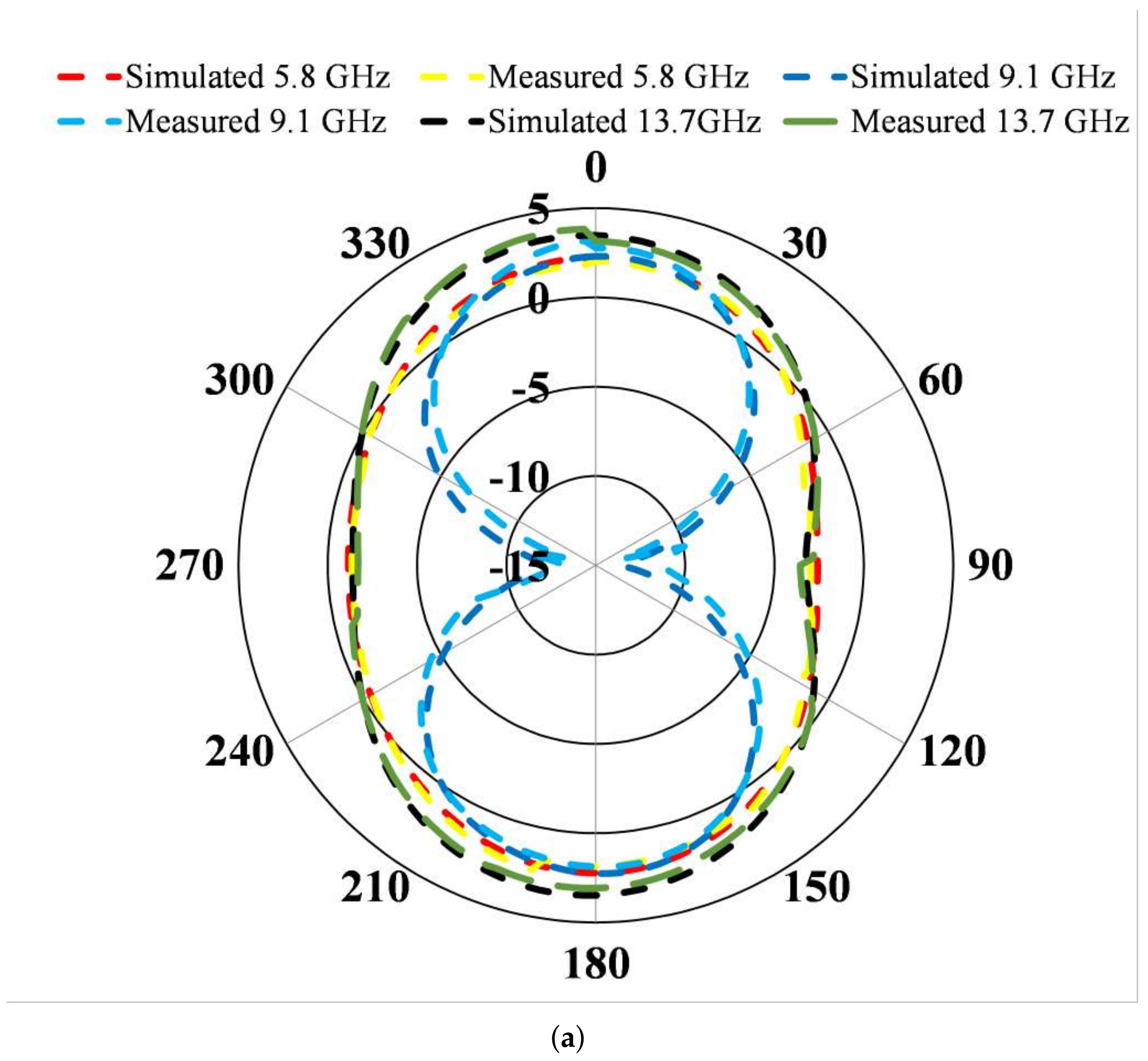
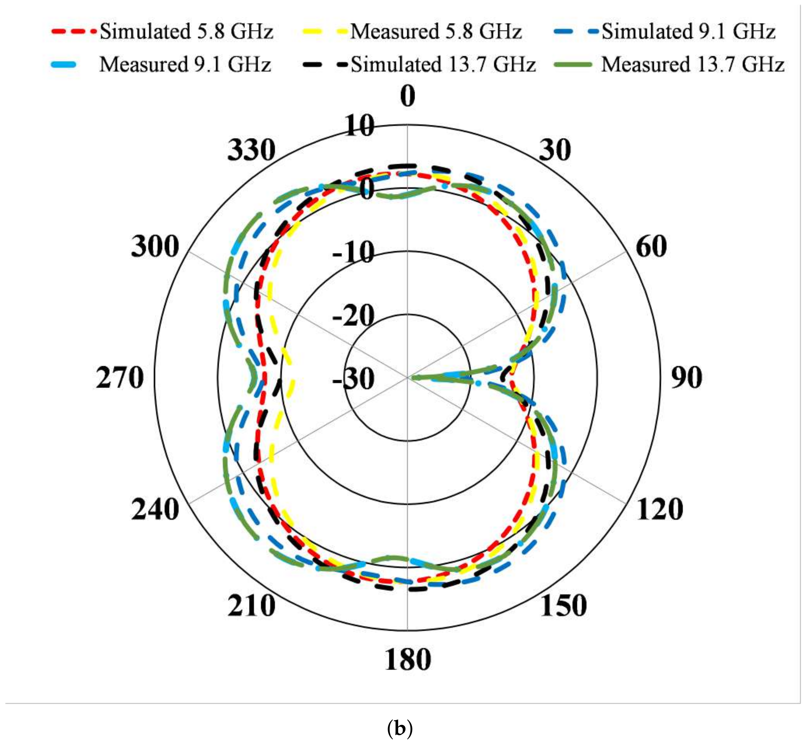
3.2. Switch Off
4. Comparison with State-of-the-Art Designs
5. Conclusions
Author Contributions
Funding
Data Availability Statement
Conflicts of Interest
References
- Abutarboush, H.F. Silver nanoparticle inkjet-printed multiband antenna on synthetic paper material for flexible devices. Alex. Eng. J. 2022, 61, 6349–6355. [Google Scholar] [CrossRef]
- Ahmad, A.; Arshad, F.; Naqvi, S.I.; Amin, Y.; Tenhunen, H.; Loo, J. Flexible and compact spiral-shaped frequency reconfigurable antenna for wireless applications. IETE J. Res. 2020, 66, 22–29. [Google Scholar] [CrossRef]
- Khan, T.; Rahman, M.; Akram, A.; Amin, Y.; Tenhunen, H. A low-cost CPW-fed multiband frequency reconfigurable antenna for wireless applications. Electronics 2019, 8, 900. [Google Scholar] [CrossRef]
- Alam, M.M.; Azim, R.; Sobahi, N.M.; Khan, A.I.; Islam, M.T. A dual-band CPW-fed miniature planar antenna for S-, C-, WiMAX, WLAN, UWB, and X-band applications. Sci. Rep. 2022, 12, 7584. [Google Scholar] [CrossRef]
- Ullah, R.; Ullah, S.; Faisal, F.; Ullah, R.; Choi, D.y.; Ahmad, A.; Kamal, B. High-gain vivaldi antenna with wide bandwidth characteristics for 5G mobile and Ku-Band radar applications. Electronics 2021, 10, 667. [Google Scholar] [CrossRef]
- Boursianis, A.D.; Papadopoulou, M.S.; Pierezan, J.; Mariani, V.C.; Coelho, L.S.; Sarigiannidis, P.; Koulouridis, S.; Goudos, S.K. Multiband patch antenna design using nature-inspired optimization method. IEEE Open J. Antennas Propag. 2020, 2, 151–162. [Google Scholar] [CrossRef]
- Awan, W.A.; Hussain, N.; Ghaffar, A.; Zaidi, A.; Naqvi, S.I.; Li, X.J. Compact flexible frequency reconfigurable antenna for heterogeneous applications. In Proceedings of the 9th IEEE Asia-Pacific Conference on Antennas and Propagation (APCAP), Xiamen, China, 4–7 August 2020; pp. 1–2. [Google Scholar]
- Shah, I.; Hayat, S.; Basir, A.; Zada, M.; Shah, S.; Ullah, S. Design and analysis of a hexa-band frequency reconfigurable antenna for wireless communication. AEU-Int. J. Electron. Commun. 2019, 98, 80–88. [Google Scholar] [CrossRef]
- Ullah, S.; Faisal, F.; Ahmad, A.; Ali, U.; Tahir, F.A.; Flint, J.A. Design and analysis of a novel tri-band flower-shaped planar antenna for GPS and WiMAX applications. J. Electromagn. Waves Appl. 2017, 31, 927–940. [Google Scholar] [CrossRef]
- Iqbal, A.; Smida, A.; Mallat, N.K.; Ghayoula, R.; Elfergani, I.; Rodriguez, J.; Kim, S. Frequency and pattern reconfigurable antenna for emerging wireless communication systems. Electronics 2019, 8, 407. [Google Scholar] [CrossRef]
- Arshad, F.; Ahmad, A.; Amin, Y.; Abbasi, M.A.B.; Choi, D.y. MIMO antenna array with the capability of dual polarization reconfiguration for 5G mm-wave communication. Sci. Rep. 2022, 12, 18298. [Google Scholar] [CrossRef]
- Uddin, M.N.; Tarek, M.N.A.; Islam, M.K.; Alwan, E.A. A Reconfigurable Beamsteering Antenna Array at 28 GHz Using a Corporate-fed 3-Bit Phase Shifter. IEEE Open J. Antennas Propag. 2023, 4, 126–140. [Google Scholar] [CrossRef]
- Desai, A.; Kulkarni, J.; Kamruzzaman, M.; Hubálovskỳ, Š.; Hsu, H.T.; Ibrahim, A.A. Interconnected CPW fed flexible 4-port MIMO antenna for UWB, X, and Ku band applications. IEEE Access 2022, 10, 57641–57654. [Google Scholar] [CrossRef]
- Yang, H.; Xi, X.; Wang, L.; Zhao, Y.; Shi, X.; Yuan, Y. Design of reconfigurable filtering ultra-wideband antenna with switchable band-notched functions. Int. J. Microw. Wirel. Technol. 2019, 11, 368–375. [Google Scholar] [CrossRef]
- Hajlaoui, E.A. New triple band electromagnetic band gap microstrip patch antenna with two shaped parasitic elements. J. Comput. Electron. 2018, 17, 452–457. [Google Scholar] [CrossRef]
- Saraswat, K.; Harish, A.R. Flexible dual-band dual-polarised CPW-fed monopole antenna with discrete-frequency reconfigurability. IET Microw. Antennas Propag. 2019, 13, 2053–2060. [Google Scholar] [CrossRef]
- Zhang, X.; Ur Rahman, S.; Cao, Q.; Gil, I.; Khan, M.I. A novel SWB antenna with triple band-notches based on elliptical slot and rectangular split ring resonators. Electronics 2019, 8, 202. [Google Scholar] [CrossRef]
- Desai, A.; Upadhyaya, T.; Patel, J.; Patel, R.; Palandoken, M. Flexible CPW fed transparent antenna for WLAN and sub-6 GHz 5G applications. Microw. Opt. Technol. Lett. 2020, 62, 2090–2103. [Google Scholar] [CrossRef]
- Kantharia, M.; Desai, A.; Upadhyaya, T.K.; Patel, R.; Mankodi, P.; Kantharia, M. High gain flexible cpw fed fractal antenna for Bluetooth/WLAN/WPAN/WiMAX applications. Prog. Electromagn. Res. Lett. 2018, 79, 87–93. [Google Scholar] [CrossRef]
- Madi, M.A.; Al-Husseini, M.; Mervat, M. Frequency tunable cedar-shaped antenna for wifi and wimax. Prog. Electromagn. Res. Lett. 2018, 72, 135–143. [Google Scholar] [CrossRef]
- Han, L.; Wang, C.; Chen, X.; Zhang, W. Compact frequency-reconfigurable slot antenna for wireless applications. IEEE Antennas Wirel. Propag. Lett. 2016, 15, 1795–1798. [Google Scholar] [CrossRef]
- Simons, R.N. Coplanar Waveguide Circuits, Components, and Systems; John Wiley & Sons: Hoboken, NJ, USA, 2004. [Google Scholar]
- Yeom, I.; Choi, J.; Kwoun, S.s.; Lee, B.; Jung, C. Analysis of RF front-end performance of reconfigurable antennas with RF switches in the far field. Int. J. Antennas Propag. 2014, 2014, 385730. [Google Scholar] [CrossRef]
- Kulkarni, J.; Sim, C.; Poddar, A.; Rohde, U.; Alharbi, A. A compact circularly polarized rotated L-Shaped antenna with J-shaped defected ground strucutre for WLAN and V2X applications. Prog. Electromagn. Res. Lett. 2022, 102, 135–143. [Google Scholar] [CrossRef]
- Yahya, M.S.; Soeung, S.; Singh, N.S.S.; Yunusa, Z.; Chinda, F.E.; Rahim, S.K.A.; Musa, U.; Nor, N.B.; Sovuthy, C.; Abro, G.E.M. Triple-Band Reconfigurable Monopole Antenna for Long-Range IoT Applications. Sensors 2023, 23, 5359. [Google Scholar] [CrossRef] [PubMed]
- Kulkarni, N.; Linus, R.M.; Bahadure, N.B. A small wideband inverted l-shaped flexible antenna for sub-6 GHz 5G applications. AEU-Int. J. Electron. Commun. 2023, 159, 154479. [Google Scholar] [CrossRef]
- Hussain, N.; Ghaffar, A.; Naqvi, S.I.; Iftikhar, A.; Anagnostou, D.E.; Tran, H.H. A conformal frequency reconfigurable antenna with multiband and wideband characteristics. Sensors 2022, 22, 2601. [Google Scholar] [CrossRef] [PubMed]
- Bharadwaj, S.S.; Sipal, D.; Yadav, D.; Koul, S.K. A compact tri-band frequency reconfigurable antenna for LTE/Wi-Fi/ITS applications. Prog. Electromagn. Res. M 2020, 91, 59–67. [Google Scholar] [CrossRef]
- Gençoğlan, D.N.; Çolak, Ş.; Palandöken, M. Spiral-Resonator-Based Frequency Reconfigurable Antenna Design for Sub-6 GHz Applications. Appl. Sci. 2023, 13, 8719. [Google Scholar] [CrossRef]
- Thenkumari, K.; Sankaran, K.S.; Mathana, J. Design and Implementation of Frequency Reconfigurable Antenna for Wi-Fi Applications. Eng. Sci. 2023, 23, 876. [Google Scholar] [CrossRef]


| Parameter | Size (mm) | Parameter | Size (mm) | Parameter | Size (mm) |
|---|---|---|---|---|---|
| Ls | 24 | L7 | 2 | W4 | 2 |
| L1 | 15.8 | L8 | 1.2 | W5 | 2.4 |
| L2 | 12 | L9 | 1 | W6 | 1 |
| L3 | 7.3 | Ws | 20 | W7 | 5 |
| L4 | 8 | W1 | 13 | Wt | 1.52 |
| L5 | 6.5 | W2 | 7.8 | g | 0.55 |
| L6 | 7 | W3 | 4.84 | C | 3 |
| Frequency (GHz) | 7.9 | 9.9 | 12.3 |
| Return loss (dB) | −38 | −15 | −21 |
| Bandwidth (GHz) | 2.76 | 0.48 | 5.3 |
| Gain (dBi) | 4.1 | 3 | 4.8 |
| Efficiency (%age) | 64.4 | 59.7 | 62.5 |
| Frequency (GHz) | 5.85 | 9.18 | 13.75 |
| Return loss (dB) | −35 | −18 | −27 |
| Bandwidth (GHz) | 0.67 | 0.9 | 5.6 |
| Gain (dBi) | 2.4 | 3.5 | 3.8 |
| Efficiency (%age) | 99 | 84 | 86 |
| Ref. | [20] | [24] | [25] | [26] | [27] | [28] | [29] | [30] | Proposed Work |
|---|---|---|---|---|---|---|---|---|---|
| Dimensions (mm) | 3900 | 900 | 4000 | 600 | 875 | 900 | 352 | 1225 | 480 |
| Material used | FR4 | FR4 | FR4 | Polyimide | Roger 5880 | Neltec | FR4 | FR4 | Roger 5880 |
| Height (mm) | 1.55 | 0.8 | 0.6 | 0.2 | 0.254 | 0.762 | 1.6 | 1.6 | 0.127 |
| No. of resonance | 6 | 1 | 3 | 3 | 3 | 4 | 2 | 5 | 5 |
| No. of switch | 6 | N/A | 2 | N/A | 1 | 2 | 2 | 3 | 1 |
| Bandwidth (MHz) | 1400 to 4600 | 1210 | N/A | 690 | 980; 2170; 1200 | 790; 100 330; 620 | N/A | 0.3 to 3.06 | 2760; 480; 5300; 670; 900 |
Disclaimer/Publisher’s Note: The statements, opinions and data contained in all publications are solely those of the individual author(s) and contributor(s) and not of MDPI and/or the editor(s). MDPI and/or the editor(s) disclaim responsibility for any injury to people or property resulting from any ideas, methods, instructions or products referred to in the content. |
© 2023 by the authors. Licensee MDPI, Basel, Switzerland. This article is an open access article distributed under the terms and conditions of the Creative Commons Attribution (CC BY) license (https://creativecommons.org/licenses/by/4.0/).
Share and Cite
Ahmad, A.; Lee, G.O.; Choi, D.-y. Design and Performance Evaluation of a Compact Frequency-Reconfigurable Coplanar-Waveguide-Fed Slotted Patch Antenna for Multi-Band Wireless Communication. Electronics 2023, 12, 3889. https://doi.org/10.3390/electronics12183889
Ahmad A, Lee GO, Choi D-y. Design and Performance Evaluation of a Compact Frequency-Reconfigurable Coplanar-Waveguide-Fed Slotted Patch Antenna for Multi-Band Wireless Communication. Electronics. 2023; 12(18):3889. https://doi.org/10.3390/electronics12183889
Chicago/Turabian StyleAhmad, Ashfaq, Geun Ok Lee, and Dong-you Choi. 2023. "Design and Performance Evaluation of a Compact Frequency-Reconfigurable Coplanar-Waveguide-Fed Slotted Patch Antenna for Multi-Band Wireless Communication" Electronics 12, no. 18: 3889. https://doi.org/10.3390/electronics12183889
APA StyleAhmad, A., Lee, G. O., & Choi, D.-y. (2023). Design and Performance Evaluation of a Compact Frequency-Reconfigurable Coplanar-Waveguide-Fed Slotted Patch Antenna for Multi-Band Wireless Communication. Electronics, 12(18), 3889. https://doi.org/10.3390/electronics12183889