Abstract
This paper presents a novel periodic grounded coplanar waveguide (GCPW) leaky-wave antenna implemented in an Indium Phosphide (InP) process. The antenna is designed to operate in the 220 GHz–325 GHz frequency range, with the goal of integrating it with an InP uni-traveling-carrier photodiode to realize a wireless transmitter module. Future wireless communication systems must deliver a high data rate to multiple users in different locations. Therefore, wireless transmitters need to have a broadband nature, high gain, and beam-steering capability. Leaky-wave antennas offer a simple and cost-effective way to achieve beam-steering by sweeping frequency in the THz range. In this paper, the first periodic GCPW leaky-wave antenna in the 220 GHz–325 GHz frequency range is demonstrated. The antenna design is based on a novel GCPW leaky-wave unit cell (UC) that incorporates mirrored L-slots in the lateral ground planes. These mirrored L-slots effectively mitigate the open stopband phenomenon of a periodic leaky-wave antenna. The leakage rate, phase constant, and Bloch impedance of the novel GCPW leaky-wave UC are analyzed using Floquet’s theory. After optimizing the UC, a periodic GCPW leaky-wave antenna is constructed by cascading 16 UCs. Electromagnetic simulation results of the leaky-wave antenna are compared with an ideal model derived from a single UC. The two design approaches show excellent agreement in terms of their reflection coefficient and beam-steering range. Therefore, the ideal model presented in this paper demonstrates, for the first time, a rapid method for developing periodic leaky-wave antennas. To validate the simulation results, probe-based antenna measurements are conducted, showing close agreement in terms of the reflection coefficient, peak antenna gain, beam-steering angle, and far-field radiation patterns. The periodic GCPW leaky-wave antenna presented in this paper exhibits a high gain of up to 13.5 dBi and a wide beam-steering range from to over the 220 GHz–325 GHz frequency range.
1. Introduction
The International Mobile Telecommunications (IMT) systems envisioned for the year 2030 and beyond place great emphasis on serving multiple users with high data rate pencil beams [1]. A key enabling factor in achieving this high data rate is the availability of a large absolute bandwidth in the THz frequency range above 100 GHz. However, one significant challenge in this frequency range is the propagation loss, which includes free space path loss and atmospheric absorption caused by water molecules [1,2]. Moreover, the saturated output power of power amplifiers implemented in various semiconductor technologies in the 100 GHz–300 GHz range is limited [3]. This limitation results in restricted transmitter output power, significantly impacting the range of THz communication. To overcome these losses, the development of high-gain on-chip antennas is seen as a key enabler for future THz communication [1,2]. Implementing high-gain antennas directly on a chip allows for integration with active devices without using any interconnects such as wirebond or flip chip [4]. The utilization of high antenna gain and the avoidance of interconnect losses enhances the effective isotropic radiated power (EIRP), which, in turn, helps mitigate propagation losses and improve the budget of a THz wireless communication link.
Another critical requirement for future IMT systems is the ability to serve multiple users with pencil beams, which provides high spatial resolution and thus avoids mutual interference. To meet this requirement, beamforming techniques are essential. Two well-known beamforming techniques are analog and digital beamforming. Analog beamforming utilizes phase shifters to steer the beam of an antenna array in a desired direction and is commonly deployed in commercial systems at millimeter-wave frequencies. However, in the THz frequency range above 100 GHz, the implementation of a phase shifter leads to a relatively high insertion loss. For example, a 120 GHz SiGe HBT phase shifter and a 250 GHz GaAs mHEMT phase shifter exhibit a mean insertion loss of 14 dB [5] and 12 dB [6], respectively. On the other hand, digital beamforming is often not deployed in the millimeter-wave frequency range due to the associated challenges of high circuit complexity, energy consumption, and operational costs [1]. Moreover, these challenges become even more pronounced in the THz frequency range. In contrast, a THz leaky-wave antenna provides a simple and cost-effective solution to steering a pencil beam in a desired direction by sweeping the frequency in the THz range.
Several THz beam-steering antennas have been experimentally demonstrated to date. For example, ref. [7] shows a microstrip leaky-wave antenna with a beam-steering range of to and a measured average gain of 11 dBi in the 230 GHz–330 GHz range. A modified version of this antenna with suppressed open stopband phenomena is demonstrated in [8]. In [9], a meandered rectangular waveguide-based traveling-wave antenna fabricated using a silicon micromachining process achieves a beam-steering range of to and a measured gain of around 29 dBi in the 230 GHz–245 GHz range. Ref. [10] presents a silicon micromachining-based THz leaky-wave antenna operating in the 288 GHz–306 GHz range, utilizing a slotted waveguide with an array of 8 slots and a simulated gain of 15 dBi. However, the beam-steering range is not demonstrated. Additionally, ref. [11] demonstrates a width trapezoidal slot in a parallel-plate waveguide achieving a measured beam-steering range of around to in the frequency range of 150 GHz–300 GHz, while [12] presents a conformal leaky-wave antenna based on a parallel-plate waveguide with a beam-steering range of more than . Furthermore, THz leaky-wave antennas based on fishnet type homogenized metasurfaces are theoretically analyzed in [13]. However, to the best of the authors’ knowledge, a coplanar waveguide (CPW)-based leaky-wave antenna operating in the THz frequency range has not yet been demonstrated. In fact, even at low frequencies well below 100 GHz, CPW-based leaky-wave antennas have been very rarely explored. At these low frequencies, two works on CPW leaky-wave antennas can be found in the literature. Ref. [14] shows a quasi-uniform leaky CPW-based slot antenna array in which the CPW signal line is loaded with radiative, transverse, series slots. The antenna operates at a center frequency of 30 GHz with a beam angle of from the broadside direction and a gain of 9.2 dBi. Ref. [15] presents a periodic CPW leaky-wave antenna, in which the CPW unit cell (UC) consists of two symmetric transversal slots and a pair of matching slots are loaded on the ground planes. The antenna operates in the frequency range of 6 GHz to 9.5 GHz, with a beam-steering range of to and a maximum gain of 15.1 dBi.
There are two key advantages of using a CPW-based leaky-wave antenna. Firstly, it can be easily connected to a THz integrated circuit (IC). The high-frequency output pads of a THz active component IC, such as a THz photodiode, are commonly designed in a CPW configuration. As a result, a CPW leaky-wave antenna can be directly connected to a THz photodiode without using a signal transition. Unlike previously demonstrated THz leaky-wave antennas, which are based on microstrip, rectangular, or parallel-plate waveguides, a CPW-based THz leaky-wave antenna does not require any signal transition (e.g., microstrip-to-CPW, rectangular waveguide-to-CPW). Consequently, a CPW-based leaky-wave antenna eliminates the insertion loss associated with a signal transition and also saves the costly chip area required in implementing a signal transition. Secondly, the measurement of a THz antenna is typically carried out using a CPW-configuration probe to make electrical contact with the antenna under test. This implies that a CPW-based leaky-wave antenna can be directly contacted by a probe without requiring an intermediate test structure. This simplifies the probe-based antenna measurement process, as there is no need to de-embed the influence of an intermediate test structure from the antenna measurement results.
The novelty of the work shown in this paper is summarized as follows. First, a periodic grounded CPW (GCPW) leaky-wave antenna achieving beam-steering in the THz frequency range of 220 GHz to 325 GHz is demonstrated for the first time. Second, the periodic GCPW leaky-wave antenna is designed based on a novel GCPW leaky-wave UC that consists of mirrored L-slots. These mirrored L-slots effectively mitigate the open stopband phenomenon and thus improve the impedance matching and realized gain of the antenna at the broadside radiation frequency. Third, a rapid method for developing periodic leaky-wave antennas is demonstrated for the first time. This method is based on an ideal model derived from a single leaky-wave UC. The ideal model requires nearly 20 times fewer hexahedral mesh cells than a full electromagnetic (EM) simulation model of the periodic GCPW leaky-wave antenna, reducing the computation time and expediting the design procedure of a periodic leaky-wave antenna. Fourth, the antenna is implemented in an Indium Phosphide (InP) process, with the goal of integrating it with an InP uni-traveling-carrier (UTC) photodiode to realize a 220 GHz–325 GHz wireless transmitter module. The photodiode has CPW configuration pads and its output power is of the order of in the THz frequency range [16,17]. The utilization of the InP process for implementing the antenna offers a key advantage, namely the leaky-wave antenna can be directly connected to an InP photodiode without using a wirebond or flip-chip interconnect. Such an interconnect results in increased manufacturing complexity, bandwidth limitation due to impedance matching, and a high insertion loss in the THz frequency range [18]. All of these drawbacks are circumvented by implementing the leaky-wave antenna using the InP process. This paper is organized as follows. Section 2 presents the antenna design procedure, including the analysis and optimization of the novel GCPW leaky-wave UC based on Floquet theory. Following this, the EM simulation results of the periodic GCPW leaky-wave antenna are compared with an ideal model derived from a single GCPW leaky-wave UC. The two design approaches are compared in terms of their reflection coefficient and beam-steering range. Section 3 presents the measurement results of a prototype of the periodic GCPW leaky-wave antenna, comparing them with the EM simulation results in terms of the reflection coefficient, beam-steering range, realized antenna gain, and far-field radiation patterns. In Section 4, the measured performance of the periodic GCPW leaky-wave antenna is compared with the state-of-the-art THz beam-steering antennas demonstrated so far. This paper is concluded in Section 5.
2. Antenna Design
2.1. GCPW Leaky-Wave UC Analysis
The antenna design begins with a GCPW that has a characteristic impedance of . A characteristic impedance of is selected for the GCPW, since it is a standard value that facilitates antenna measurement. The GCPW is implemented on an InP substrate with a dielectric constant () of and a loss tangent () of at 300 GHz [19,20]. Gold (Au) metal layers are provided on both sides of the InP substrate. The thickness of the InP substrate and the Au metal layers are 50 μm and 1 μm, respectively. To determine the signal line width (w) and slot width (s) required for achieving a GCPW, the design parameters are calculated using Advanced Design System (ADS) LineCalc software Version 2023. The calculated values are subsequently optimized based on an EM simulation performed using CST Microwave Studio software Version 2022. The optimized dimensions for an InP-based GCPW are found to be 70 μm and 71 μm for the signal line and slot width, respectively. The GCPW is modified to become leaky by incorporating a waveguide discontinuity in the lateral ground planes of the GCPW. The waveguide discontinuity is designed in the form of an L-slot on each of the lateral ground planes of the GCPW. These L-slots are mirrored with respect to both the longitudinal and transverse axes of the GCPW. The mirroring of L-slots is carried out to mitigate the open stopband phenomena of a periodic leaky-wave antenna, which is explained later in this section. This structure represents a single UC of the periodic GCPW leaky-wave antenna demonstrated in this paper, as illustrated in Figure 1a. The dimensions of the GCPW leaky-wave UC are shown in Table 1. The length of the UC and hence the periodicity of the leaky-wave antenna is calculated as one guided wavelength () at the desired center frequency, of 272.5 GHz, using Equation (1).
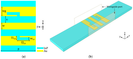
Figure 1.
A schematic of the GCPW leaky-wave UC. (a) Top view showing dimensions of the UC. (b) EM simulation model of the UC.

Table 1.
Dimensions of the GCPW leaky-wave UC.
In Equation (1), the parameters and denote the speed of light and the effective dielectric constant, respectively. The of an InP-based GCPW is calculated as using the ADS LineCalc software. Consequently, the length of the UC, and hence the periodicity (p) of the leaky-wave antenna, is calculated as 384 μm using Equation (1). The value of p is subsequently optimized based on an EM simulation performed using CST Microwave Studio software. The optimized value of p is found to be 366 μm.
The UC has a leaky nature due to the introduction of L-slots in its lateral ground planes. As a result, a complex propagation constant () is associated with the UC, which is composed of a non-zero attenuation constant () and a non-zero phase constant () as shown by Equation (2).
The attenuation constant () signifies the leakage rate of the periodic leaky-wave antenna, while the phase constant () is useful in determining the beam-steering angle of the periodic leaky-wave antenna. Therefore, in order to design a periodic leaky-wave antenna, the values of and should be known in the desired frequency range of 220 GHz–325 GHz. For this purpose, the S-parameters of the GCPW leaky-wave UC are simulated using CST Microwave Studio software Version 2022. The simulation model of the UC is shown in Figure 1b, indicating the position of waveguide ports configured at both ends of the GCPW. The boundary conditions used for this simulation consist of open boundaries along the x and y axes, an electric boundary along the negative z axis (i.e., at the bottom ground plane of the UC), and an open add space boundary along the positive z axis (i.e., at the top of the UC). The simulated S-parameters are converted to the A, B, C, and D parameters of the UC. The A, B, C, and D parameters of the GCPW leaky-wave UC are used to calculate the values of and by using Equation (3). Note that the Equation (3) assumes an infinite periodic structure, i.e., an infinitely long GCPW composed of a one-dimensional (1D) cascade of the leaky-wave UCs repeated at periodic intervals of p. According to the Floquet’s theory of periodic structures, Bloch waves propagate on the periodically-loaded GCPW and the Bloch impedance () is calculated using the A, B, and D parameters of the GCPW leaky-wave UC as shown in Equation (4) [21].
The obtained from Equation (3) corresponds to the phase constant of the fundamental GCPW mode, which is a guided mode with a phase velocity () less than . This implies that 1, where denotes the free space wavenumber (Note, and ). A 1D periodic array of the leaky-wave UCs leads to the generation of an infinite number of space harmonics, whose phase constants are given by Equation (5) [22].
In Equation (5), denotes the phase constant of the nth space harmonic. A space harmonic with (i.e., 1) is a leaky wave that is capable of radiating into free space. We already know that 1 for a guided GCPW mode; therefore, in order to make 1, n should be a negative integer. The value of n is selected as in order to design a beam-steering antenna with a single main lobe. Consequently, the phase constant of the first leaky wave () that causes radiation into free space is calculated by using Equation (6) [22].
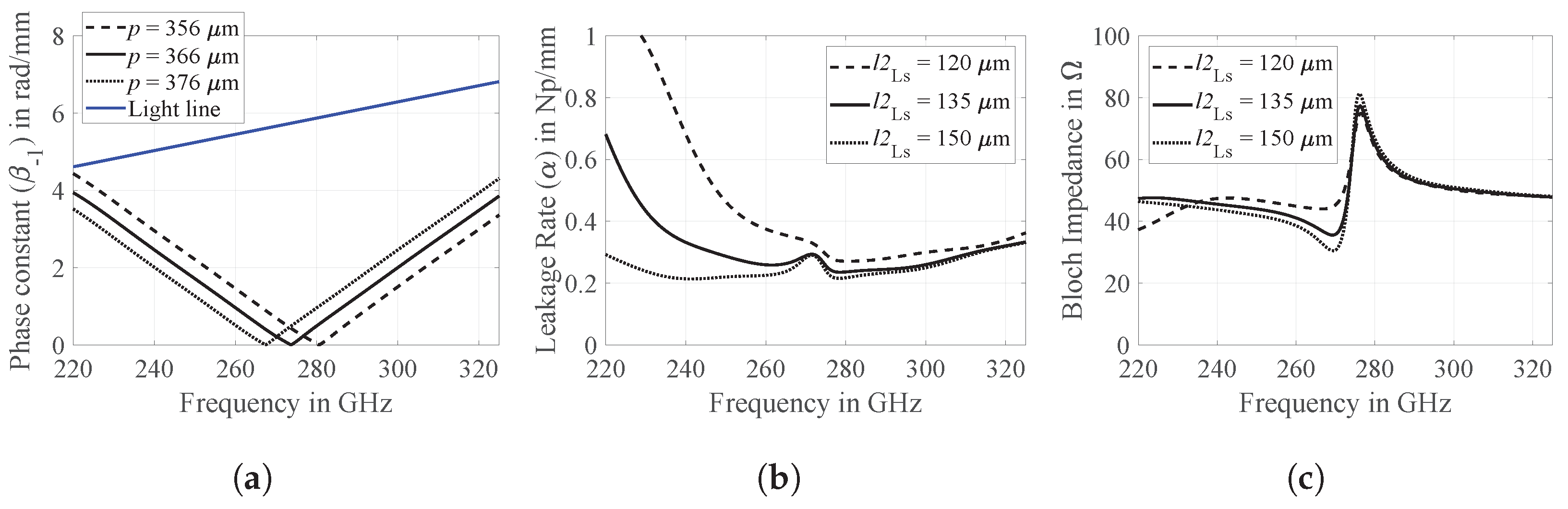
In Equation (6), the value of the leaky-wave UC period, p, is varied in three steps namely, 356 μm, 366 μm, and 376 μm (note that these values are close to the initially calculated value of 384 μm using Equation (1)). An EM simulation of the GCPW leaky-wave UC is carried out corresponding to all three values of p. The simulated S-parameters are converted to the A, B, C, and D parameters, which are used to calculate the first leaky-wave phase constant, , by using Equations (3) and (6). The resultant phase constant curves over the target frequency range of 220 GHz–325 GHz are shown in Figure 2a. In each of these three cases, the phase constant curve remains below the light line (i.e., ) and, hence, in all three cases, the first space harmonic or the first leaky wave radiates into free space in the 220 GHz–325 GHz range. The frequency at which the phase constant becomes null corresponds to a broadside radiation. The frequency of broadside radiation decreases with an increase in the value of p and a broadside radiation at the desired center frequency of 272.5 GHz is obtained for a periodicity of 366 μm. The range of frequencies on the left and right sides of the null point signifies radiation in backward and forward quadrants, respectively. The total length of the L-slot (i.e., ) should be approximately half of the guided wavelength (i.e., , where p is equal to the optimized at the desired center frequency). As a result, the L-slot functions as a waveguide discontinuity that leads to leaky-wave radiation. Between these two values, the longitudinal length of the L-slot () is kept relatively longer than the transverse length (). This choice results in a smaller width of the lateral ground-plane of the GCPW structure. As a result, the overall width of the leaky-wave antenna is reduced, allowing the potential formation of a 1D array of such leaky-wave antennas in the future. This array can be created while still maintaining an antenna spacing of less than half of the free-space wavelength. Consequently, the problem of grating lobes could be avoided when configuring a 1D array of these leaky-wave antennas. Taking this rationale into account, and considering the manufacturing constraints of the InP process used in this work, is set to 41 μm and the initial value of is calculated as . Starting with this initial value, the value of is optimized based on electromagnetic simulations of the GCPW leaky-wave UC. In this case, the derived A, B, C, and D parameters are used to calculate the leakage rate, , and the Bloch impedance, , using Equation (3) and Equation (4), respectively. The value of is varied in steps of 120 μm, 135 μm, and 150 μm (these values are close to the initially calculated value of 142 μm) and the resultant curves of and over the target frequency range of 220 GHz–325 GHz are shown in Figure 2b,c, respectively. For of 120 μm, a high leakage rate, , is observed at the starting frequency of 220 GHz, which implies a small effective aperture and, hence, a poor radiation efficiency for a periodic leaky-wave antenna. On the other hand, for of 150 μm, the leakage rate is quite low; however, the corresponding Bloch impedance, , shows a larger deviation from the desired value. Consequently, the optimum value of is 135 μm, which provides a good trade-off between a sufficiently low leakage rate and a Bloch impedance that stays close to for most of the target frequency range.
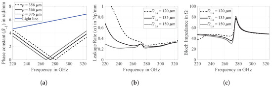
Figure 2.
Simulative analysis of GCPW leaky-wave UC over target frequency range. (a) Phase constant of first space harmonic. (b) Leakage rate. (c) Bloch impedance.
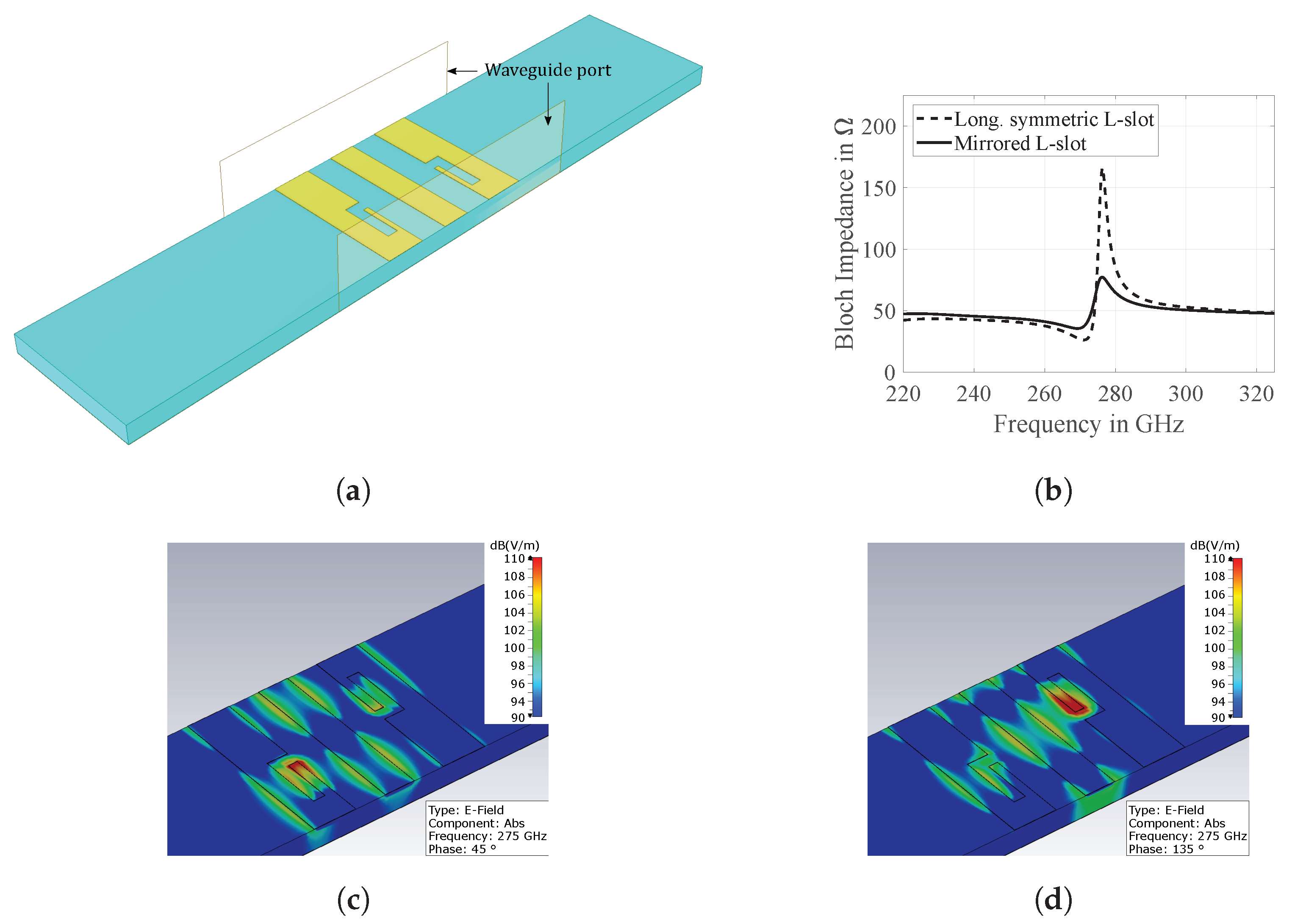
In a periodic leaky-wave antenna, a mismatch between the Bloch wave impedance, , and the load impedance, (), of a periodically-loaded waveguide occurs around the broadside radiation frequency, which results in a somewhat reduced efficiency of the broadside radiation, also known as the open stopband phenomenon [22]. The GCPW leaky-wave UC shown in Figure 1a uses mirrored L-slots, which help to mitigate the impedance mismatch between and and hence mitigate the open stopband phenomenon to a large extent. In order to prove this, a GCPW leaky-wave UC with longitudinally symmetric L-slots is simulated using waveguide ports on either end, as shown in Figure 3a. The dimensions of this UC are the same as those shown in Table 1.

Figure 3.
(a) GCPW leaky-wave UC with longitudinally symmetric L-slots. (b) Simulated Bloch impedance of GCPW leaky-wave UCs with longitudinally symmetric L-slots and mirrored L-slots. (c) Simulated E-field of the GCPW leaky-wave UC at center frequency 275 GHz and phase angle. (d) Simulated E-field of the GCPW leaky-wave UC at center frequency 275 GHz and phase angle.
The extracted for both the GCPW leaky-wave UCs, i.e., with the longitudinally symmetric L-slots and the mirrored L-slots, are shown in Figure 3b. It is observed that the longitudinally symmetric L-slots result in a of at the broadside radiation frequency, which will lead to a maximum reflection coefficient () of using a of in Equation (7) [22]. On the other hand, the mirrored L-slots result in a , which stays close to for most of the target frequency range. At the broadside radiation frequency, shows a maximum jump of at the broadside radiation frequency. This leads to an improvement of .
Finally, the distribution of the electric field (E-field) is analyzed to validate the design procedure of the GCPW leaky-wave UC outlined in this section. The simulated E-field of the GCPW leaky-wave UC at the center frequency of 275 GHz and at phase angles of and is depicted in Figure 3c,d, respectively. The location of the waveguide ports used in this simulation is the same as that depicted in Figure 1b, and the boundary conditions employed are consistent with those detailed in Figure 1b. It is evident that a GCPW mode propagates along the host signal line, with the maximum absolute value of the E-field observed around the first L-slot at a phase angle in Figure 3c, and around the mirrored L-slot at a phase angle in Figure 3d. This E-field analysis confirms that the mirrored L-slots function as waveguide discontinuities within the host GCPW structure, leading to leaky-wave radiation. Secondly, the maximum intensity of the E-field observed within the two L-slots aligns with a phase difference of approximately . In other words, the phase centers of the mirrored L-slot radiators are spaced a quarter of a guided wavelength apart. As mentioned in the design procedure, the total length of the GCPW leaky-wave UC is chosen to match one guided wavelength at the center frequency, and the total length of each of these mirrored L-slots is set to half of the guided wavelength at the center frequency. Consequently, the phase centers of the mirrored L-slots should be a quarter of the guided wavelength apart at the center frequency, confirming that the observed E-field maxima align with the fundamental design concept of this GCPW leaky-wave UC. The H-field analysis of the GCPW leaky-wave UC reaffirms these findings.
2.2. GCPW Leaky-Wave Antenna: Full EM Simulation vs. Ideal Model
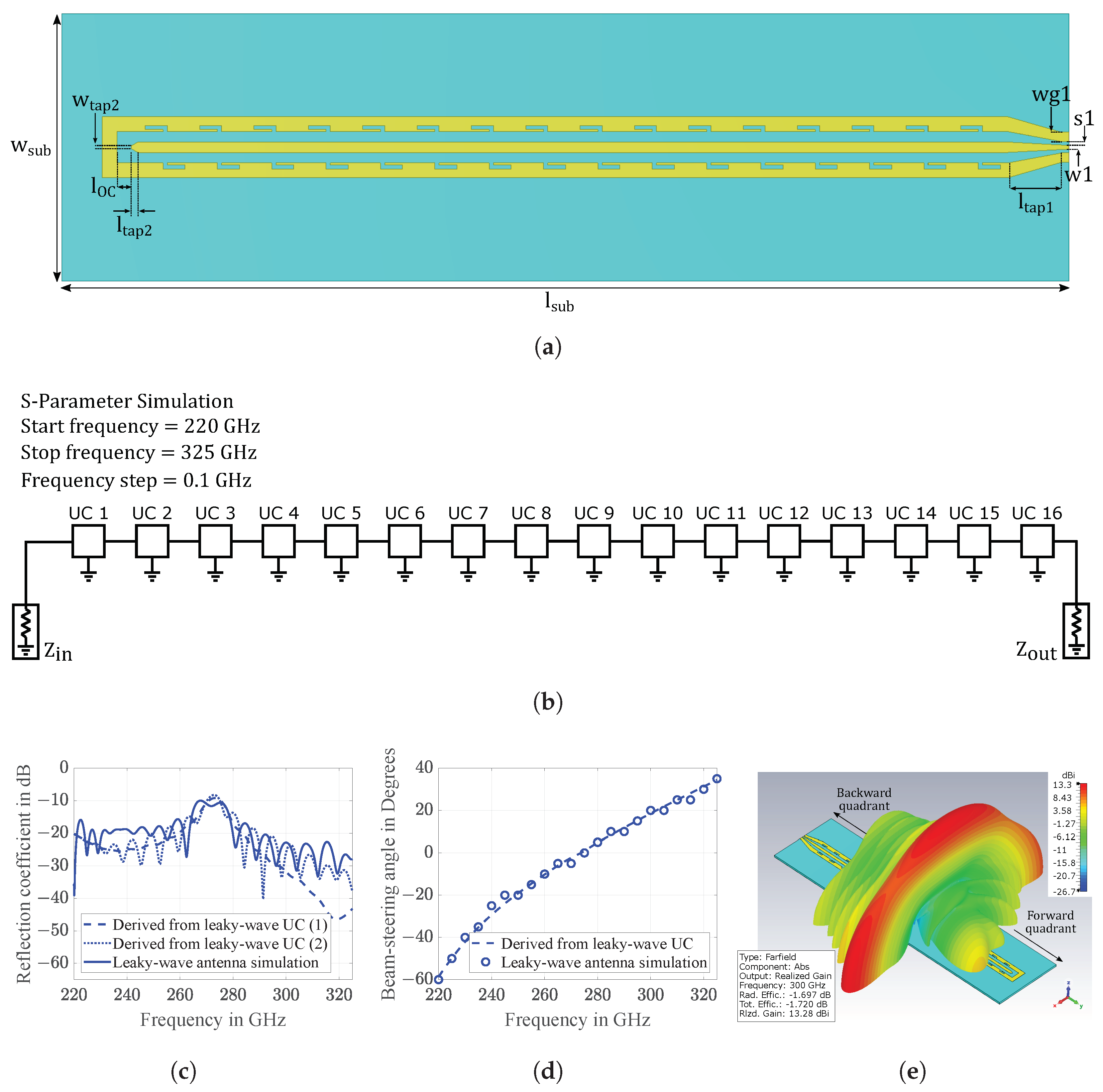
After optimizing the GCPW leaky-wave UC design, a total of 16 UCs are cascaded to build the periodic GCPW leaky-wave antenna. A high number of UCs, combined with a low leakage rate (), ensures that, as the first space harmonic (with phase constant ) propagates along the periodically-loaded GCPW, most of the energy is leaked and radiated into free space by the time the wave reaches the last UC of a 1D cascaded structure. A schematic of the periodic GCPW leaky-wave antenna is shown in Figure 4a.
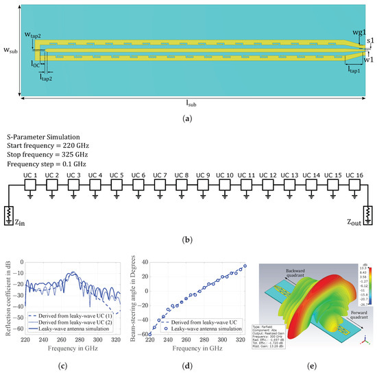
Figure 4.
(a) A schematic of the periodic GCPW leaky-wave antenna. (b) Ideal model derived from a single GCPW leaky-wave UC in ADS. (c) Comparison of reflection coefficient derived from leaky-wave UC and full-wave EM simulation of periodic GCPW leaky-wave antenna. (d) Comparison of beam-steering range derived from leaky-wave UC and full-wave EM simulation of periodic GCPW leaky-wave antenna. (e) Simulated 3D far-field radiation pattern at 300 GHz.
In this schematic, besides the GCPW leaky-wave UCs, a GCPW feed structure and a GCPW open circuit termination are added to realize the periodic leaky-wave antenna. The feed structure is designed to enable antenna measurement using a ground signal ground (GSG) probe. The GSG probe used for measurement has a pitch of 100 μm, according to which the signal line width and the slot width of the GCPW feed (, ) are adjusted to achieve a characteristic impedance of . This feed is connected to the 1D periodic array of leaky-wave UCs using a tapered transition. The antenna is terminated with a GCPW open circuit. Note that the beam-steering antennas realized at low frequencies, which are measured using coaxial connectors, are terminated with a matched load, whereas the antenna shown here operates at a high frequency of 220 GHz–325 GHz, which is measured with a probe. Moreover, a matched load cannot be realized due to the manufacturing process and the probe-based antenna measurement setup used in this work. In the GCPW open circuit termination of the antenna, the GCPW signal line is tapered to mitigate the parasitic fringing capacitance that exists at the open end of the signal line. This tapering leads to an improvement in the impedance matching at the broadside radiation frequency. The dimensions of the periodic GCPW leaky-wave antenna are shown in Table 2.
Table 2.
Dimensions of the periodic GCPW leaky-wave antenna.
An EM simulation of the antenna is performed using CST Microwave Studio software. The simulated reflection coefficient and beam-steering angle of the antenna are compared with those of an ideal model derived from a single GCPW leaky-wave UC shown in Figure 1. The ideal model shown in Figure 4b is built using ADS software. In this model, the simulated S-parameters of a single GCPW leaky-wave UC are imported into ADS software. To replicate the complete radiating structure of the antenna, the S-parameters of a single UC are cascaded 16 times. The cascade of 16 UCs is terminated on either end using an input impedance () and an output impedance (). The ADS simulation is performed using a start frequency of 220 GHz and a stop frequency of 325 GHz. The S-parameter simulations in ADS are performed in steps of 0.1 GHz. Two different simulations are performed using this model. In the first case, matched terminations are used at the input as well as the output (i.e., and ). In the second case, a matched termination is used at the input, whereas a very high impedance is used at the output in order to mimic an open circuit termination (i.e., and ). The reflection coefficients of the full-wave EM simulation and two different cases of the ideal ADS model derived from the leaky-wave UC are compared in Figure 4c. In Figure 4c, the dashed curve (marked as ‘(1)’) shows the simulated reflection coefficient of the ideal ADS model using and the dotted curve (marked as ‘(2)’) shows the simulated reflection coefficient of the ideal ADS model using and . In the former case, the reflection coefficient forms a smooth curve, whereas, in the latter case, the reflection coefficient shows ripples along with some degradation. Furthermore, the reflection coefficient curves of the second case and the full EM simulation model of the leaky-wave antenna exhibit a similar progression over the frequency range of 220 GHz to 325 GHz. The slight discrepancy between the dotted and solid curves in Figure 4c, specifically the frequency offset in their peaks, can be attributed to the distinct methods of implementing open-circuit termination in the two models. The ADS model shown in Figure 4b employs a very high output impedance value () to mimic an open-circuit termination, whereas the full EM simulation model in CST (see Figure 4a) employs a modified GCPW open-circuit termination along with a tapered feed structure. Therefore, a minor deviation between these two curves is to be expected.
The beam-steering angle is also compared between the two models. For the EM simulation model, the far-field radiation pattern of the antenna is simulated in the 220 GHz–325 GHz range at 5 GHz intervals. The main lobe direction of each simulated far-field radiation pattern provides the beam-steering angle over the target frequency range shown in Figure 4d. In the ideal model, the beam-steering angle is calculated using the phase constant of the first space harmonic, causing radiation into free space, as shown in Equation (8). Furthermore, the procedure of obtaining the value of from a single leaky-wave UC has already been explained in Section 2.1.
The beam-steering angle over the target frequency range obtained from the EM simulation of the periodic GCPW leaky-wave antenna and the ideal model derived from a single GCPW leaky-wave UC show a very good match. It is worth noting that the simulation model of the periodic GCPW leaky-wave antenna employs a hexahedral mesh with approximately million mesh cells, whereas the simulation model of a single leaky-wave UC used to construct the ideal model in ADS software uses a hexahedral mesh with only million mesh cells. As a result, the significant reduction in mesh cells by nearly 20 times leads to a substantial reduction in computation time. The excellent agreement observed in the results obtained from both approaches shows that the analysis of leaky-wave UCs combined with an ideal simulation in ADS software can expedite the design process of a periodic leaky-wave antenna. The simulated far-field radiation pattern at 300 GHz (see Figure 4e) shows a realized gain of 13.3 dBi and a total antenna efficiency of ≈. The radiation pattern has a fan-shaped beam with a narrow half power beam width of ≈ in the beam-steering plane. The fan-shaped beam tilts in the forward and backward quadrant with increasing and decreasing frequency, respectively.
3. Probe-Based Antenna Measurement Results
A prototype of the periodic GCPW leaky-wave antenna is depicted in Figure 5a. The antenna is measured using a GSG probe operating in the WR3 (220 GHz–325 GHz) band with a 100 μm pitch. The measurements of the reflection coefficient and radiation characteristics of the antenna are conducted using the probe-based antenna measurement setup shown in Figure 5b.
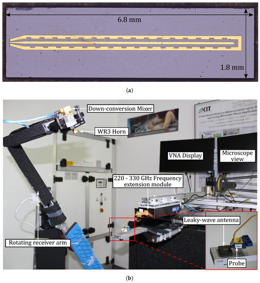
Figure 5.
(a) Microscope photo of the antenna prototype. (b) Probe-based antenna measurement setup with the rotating receiver arm aligned in the beam-steering plane of the leaky-wave antenna.
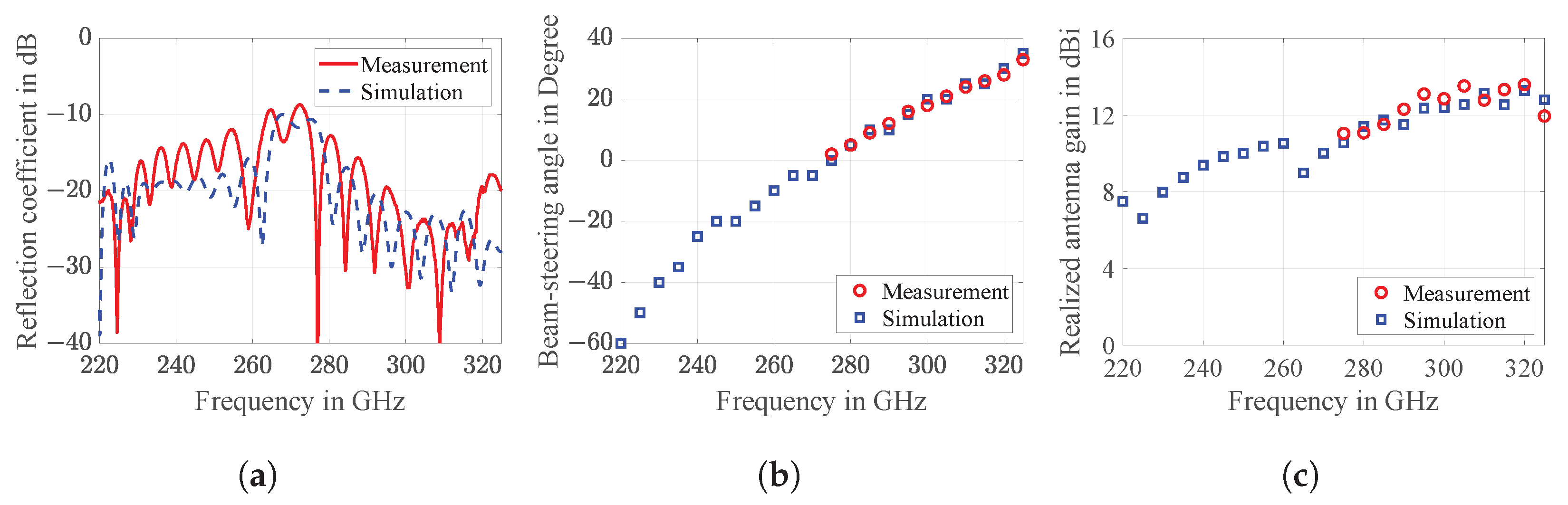
The operational principle of this setup is described in detail in [23,24]. Prior to the antenna measurement, three calibrations are performed. Firstly, a one-port waveguide calibration is conducted at the output of the VDI frequency extension module, which operates in the 220 GHz–325 GHz band. Secondly, a gain calibration is carried out using two standard gain horn antennas—one at the output of the frequency extension module and the other on the rotating receiver arm. Thirdly, following the gain calibration, the WR3 GSG probe is connected to the output of the frequency extension module, and a one-port open-short-load calibration is performed using an impedance standard substrate. As a result, the reference plane for the antenna measurement is set up at the tip of the probe and the measurement errors caused by a probe contacting the antenna are calibrated out. The details of this procedure are given in [23]. Once the reference plane is established at the probe tip, the reflection coefficient and radiation characteristics of the antenna are measured. The measurement results are compared with the EM simulation results of the periodic GCPW leaky-wave antenna and are presented in Figure 6. It should be noted that the probe is expected to have a certain influence on the antenna measurement at such high frequencies [25,26]. Incorporating a probe into the EM simulation of a 220 GHz to 325 GHz range requires replicating the constructional details of the probe model used in the measurement, with a very high degree of accuracy. Moreover, this leads to a significant increase in the EM simulation time. While this is an ongoing research topic and not the main focus of this work, it could potentially serve as a subject for future research endeavors. The measured and simulated reflection coefficients, as depicted in Figure 6a, exhibit a very good match with a minor frequency shift. The measured reflection coefficient remains below −10 dB for the majority of the target frequency range. The slight portion where the measured reflection coefficient surpasses −10 dB corresponds to the frequency of broadside radiation, which is also observed in the simulation results. This behavior is expected based on the findings of the Bloch impedance analysis conducted in Section 2. The measured and simulated beam-steering angles and the achieved peak antenna gain over the target frequency range of 220 GHz–325 GHz are illustrated in Figure 6b,c, respectively. The measured and simulated curves in Figure 6b,c exhibit a strong agreement. The measured beam-steering angle ranges from near broadside radiation (≈) at 275 GHz to an angle of ≈ in the forward quadrant at 325 GHz. Consequently, the beam-steering rate of the periodic GCPW leaky-wave antenna is measured to be ≈. Additionally, Figure 6c demonstrates that the measured peak antenna gain varies between 11 dBi and 13.5 dBi in the 275 GHz–325 GHz range.
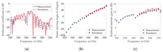
Figure 6.
Measurement and simulation results of periodic GCPW leaky-wave antenna (a) Reflection coefficient. (b) beam-steering range. (c) Realized antenna gain.
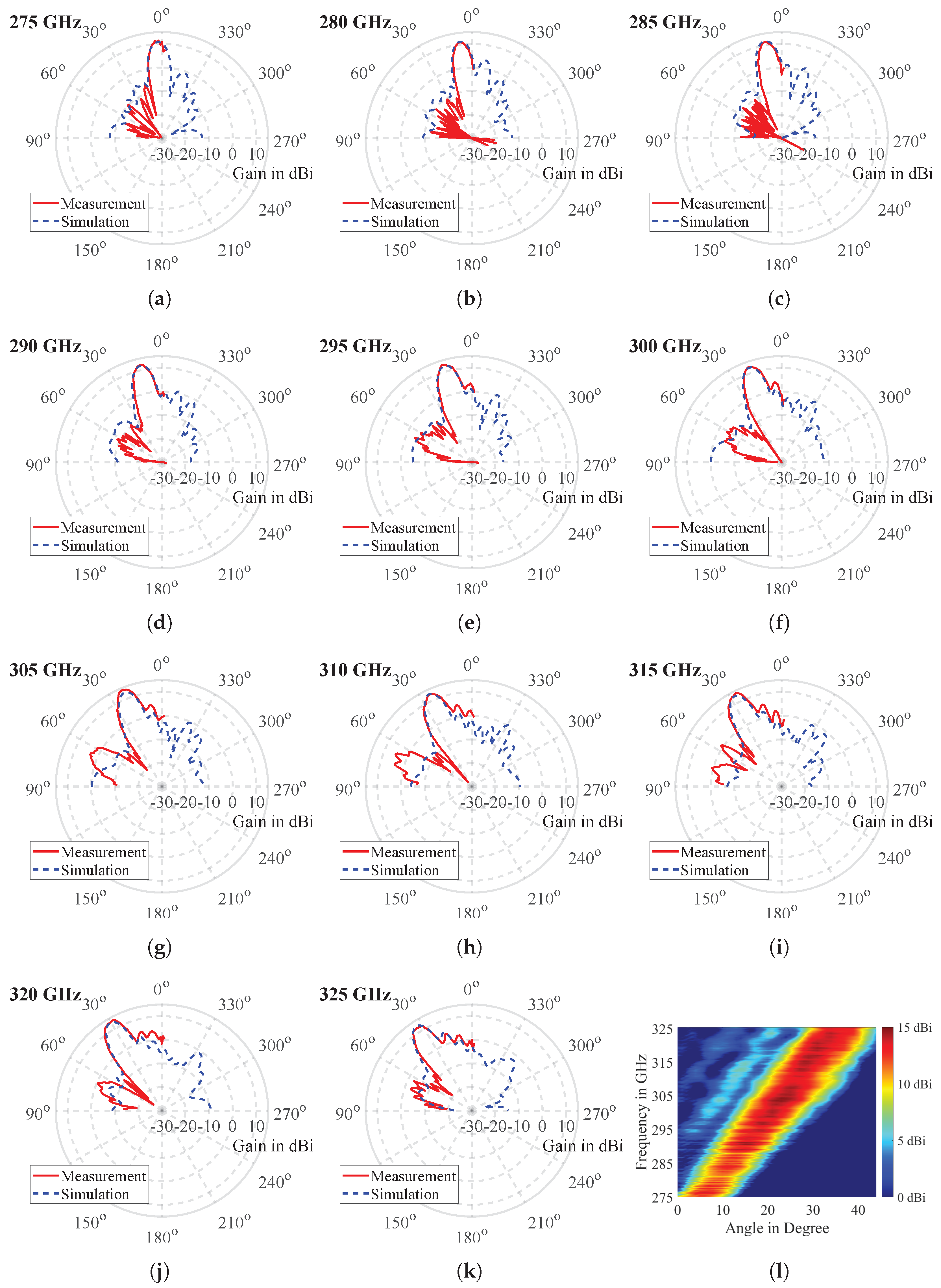
The far-field radiation pattern of the antenna is measured starting at a frequency of 275 GHz up to a maximum frequency of 325 GHz, with intervals of 5 GHz. The corresponding measured and simulated far-field radiation patterns for these frequencies are depicted in Figure 7a–k. Figure 7l shows a 2D plot of the measured far-field radiation pattern in the upper frequency range of the leaky-wave antenna. This plot shows how the leaky-wave antenna beam continuously steers in the forward quadrant as the frequency is swept across the target THz range. As observed previously, the antenna beam gradually steers in the forward quadrant as the frequency increases, transitioning from near broadside radiation at 275 GHz to an angle of approximately at 325 GHz. There is a remarkable agreement between the measured and simulated main lobes. However, some discrepancy is noticed in the side lobe levels between the measured and simulated patterns. The measured half power beam width for each of the far-field radiation pattern is ≈. It is important to emphasize that the radiation characteristics of the leaky-wave antenna in the beam-steering plane, encompassing its beam-steering angle and peak antenna gain, shown in Figure 6b,c, respectively, can only be measured within the forward quadrant. This forward quadrant encompasses a sector originating from the antenna’s boresight direction and extending towards the open end of the leaky-wave antenna. This measurement scope pertains to the upper frequency range of the leaky-wave antenna, spanning from 275 GHz to 325 GHz. Contrastingly, within the backward quadrant, which comprises the remaining sector extending toward the feed end of the antenna and corresponding to the antenna’s lower frequency range (specifically, from 220 GHz up to roughly 275 GHz), certain antenna characteristics—namely its radiation pattern in the beam-steering plane, beam-steering angle, and peak antenna gain—cannot be measured due to the following reason. When the rotating receiver arm, as illustrated in Figure 5b, is positioned within the backward quadrant to measure the antenna’s radiation characteristics, it is shadowed by the probe that contacts the antenna and the subsequent frequency extension module. Therefore, the measurement constraint is caused by the mechanical limitations imposed by the antenna measurement setup used in this work.

Figure 7.
Farfield radiation patterns measured in the beam-steering plane at: (a) 275 GHz, (b) 280 GHz, (c) 285 GHz, (d) 290 GHz, (e) 295 GHz, (f) 300 GHz, (g) 305 GHz, (h) 310 GHz, (i) 315 GHz, (j) 320 GHz and (k) 325 GHz. (l) 2D plot of measured beam-steering range from 275 GHz to 325 GHz.
4. Comparison with State-of-the-Art THz Beam-Steering Antennas and Future Outlook
The measured performance of the novel periodic GCPW leaky-wave antenna shown in this paper is compared with the state-of-the-art THz beam-steering antennas demonstrated so far in Table 3. The antenna demonstrated in this paper is the only GCPW-based THz beam-steering antenna demonstrated to date. Due to its GCPW feed, it can be measured using a GSG probe and it can be integrated with an InP UTC photodiode without requiring any signal transition or an interconnect, respectively. Hence, no additional area is required for the implementation of a signal transition, which saves design effort, chip area, and cost. In addition, the insertion loss associated with a signal transition is avoided.
Table 3.
Comparison with state-of-the-art THz beam-steering antennas.
On comparing the periodic GCPW leaky-wave antenna shown in this paper with other state-of-the-art THz beam-steering antennas in terms of relative bandwidth, realized gain, beam-steering range, and electrical length at the center frequency of operation, the antenna shown in this paper offers a very good trade-off of these parameters. Furthermore, the width of the periodic GCPW leaky-wave antenna, i.e., the edge-to-edge distance of its lateral ground planes containing the mirrored L-slots, is less than half of the free-space wavelength at its highest frequency of operation. Therefore, in the future, an array of these leaky-wave antennas can be formed, with each antenna being connected to a phase shifter. As a result, a pencil beam, which can be steered in two dimensions by scanning the frequency in THz range, can be achieved.
5. Conclusions
This paper presents a novel periodic GCPW leaky-wave beam-steering antenna designed to operate across a broad frequency range of 220 GHz–325 GHz, encompassing an absolute bandwidth of 105 GHz and a relative bandwidth of %. The antenna is constructed using a GCPW leaky-wave UC with two mirrored L-slots. A comprehensive analysis is conducted on the leakage rate, phase constant, and Bloch impedance of this leaky-wave UC. A comparison is made between the Bloch impedance of the mirrored L-slots and longitudinally symmetric L-slots, demonstrating the effective mitigation of the open stopband phenomenon, which is a common issue encountered in periodic leaky-wave antennas. The EM simulation results of the periodic GCPW leaky-wave antenna are compared with the outcomes obtained from an ideal model derived from a single leaky-wave UC. Remarkably, a good agreement is observed between the results obtained using these two approaches. Moreover, the ideal model significantly reduces the required number of hexahedral mesh cells by nearly 20 times compared to a full EM simulation model, thus providing a novel and efficient method for expediting the development process of periodic leaky-wave antennas. To validate the simulation results, probe-based antenna measurements are conducted, demonstrating close agreement in terms of reflection coefficient, peak antenna gain, beam-steering angle, and far-field radiation patterns. The measured reflection coefficient of the antenna remains below −10 dB for the majority of the 220 GHz–325 GHz frequency range. Additionally, the antenna achieves a peak gain of up to 13.5 dBi at 305 GHz. The antenna exhibits beam-steering capability with a measured scan rate of ≈, enabling a wide beam-steering range from to in the 220 GHz–325 GHz frequency range. The measured half power beam width of the antenna is ≈ in the beam-steering plane of the target frequency range.
Author Contributions
Conceptualization, A.B.; methodology, A.B.; software, A.B.; validation, A.B. and M.K.; formal analysis, A.B., M.K. and J.D.; investigation, A.B.; original draft preparation and writing, A.B.; review and editing, A.B., M.K., J.D. and T.Z.; manufacturing, P.L. and A.S.; project administration, T.Z.; funding acquisition, A.B., A.S. and T.Z. All authors have read and agreed to the published version of the manuscript.
Funding
The authors acknowledge the financial support by the Federal Ministry of Education and Research of Germany in the project “Open6GHub” (grant number: 16KISK010).
Acknowledgments
The authors express their gratitude to Reza Akbarzadeh Naseri for dicing the Indium Phosphide wafer and to Andreas Lipp for preparing the prototypes for measurements.
Conflicts of Interest
The authors declare no conflict of interest.
Abbreviations
The following abbreviations are used in this manuscript:
| CPW | Coplanar waveguide |
| EM | Electromagnetic |
| GCPW | Grounded coplanar waveguide |
| GSG | Ground Signal Ground |
| IMT | International mobile telecommunication |
| InP | Indium Phosphide |
| THz | Terahertz |
| UC | Unit cell |
| UTC | Uni traveling carrier |
References
- Future Technology Trends of Terrestrial International Mobile Telecommunications Systems towards 2030 and Beyond. Available online: https://www.itu.int/dms_pub/itu-r/opb/rep/R-REP-M.2516-2022-PDF-E.pdf (accessed on 14 July 2023).
- Rappaport, T.S.; Xing, Y.; Kanhere, O.; Ju, S.; Madanayake, A.; Mandal, S.; Alkhateeb, A.; Trichopoulos, G.C. Wireless Communications and Applications Above 100 GHz: Opportunities and Challenges for 6G and Beyond. IEEE Access 2019, 7, 78729–78757. [Google Scholar] [CrossRef]
- Buckwalter, J.F.; Rodwell, M.J.W.; Ning, K.; Ahmed, A.; Arias-Purdue, A.; Chien, J.; O’Malley, E.; Lam, E. Fundamental Limits of High-Efficiency Silicon and Compound Semiconductor Power Amplifiers in 100—300 GHz Bands. ITU J. Future Evol. Technol. 2021, 2. Available online: https://www.itu.int/dms_pub/itu-s/opb/jnl/S-JNL-VOL2.ISSUE7-2021-A04-PDF-E.pdf (accessed on 14 July 2023).
- Zhang, Y.P.; Liu, D. Antenna-on-Chip and Antenna-in-Package Solutions to Highly Integrated Millimeter-Wave Devices for Wireless Communications. IEEE Trans. Antennas Propag. 2009, 57, 2830–2841. [Google Scholar] [CrossRef]
- Sarkas, I.; Laskin, E.; Hasch, J.; Chevalier, P.; Voinigescu, S.P. Second generation transceivers for D-band radar and data communication applications. In Proceedings of the 2010 IEEE MTT-S International Microwave Symposium, Anaheim, CA, USA, 23–28 May 2010; pp. 1328–1331. [Google Scholar] [CrossRef]
- Müller, D.; Reiss, S.; Massler, H.; Tessmann, A.; Leuther, A.; Zwick, T.; Kallfass, I. A H-band reflective-type phase shifter MMIC for ISM-Band applications. In Proceedings of the 2014 IEEE MTT-S International Microwave Symposium (IMS2014), Tampa, FL, USA, 1–6 June 2014; pp. 1–4. [Google Scholar] [CrossRef]
- Lu, P.; Haddad, T.; Sievert, B.; Khani, B.; Makhlouf, S.; Dülme, S.; Estévez, J.F.; Rennings, A.; Erni, D.; Pfeiffer, U.; et al. InP-Based THz beam-steering Leaky-Wave Antenna. IEEE Trans. Terahertz Sci. Technol. 2021, 11, 218–230. [Google Scholar] [CrossRef]
- Haddad, T.; Biurrun-Quel, C.; Lu, P.; Kaya, H.; Mohammad, I.; Stöhr, A. Suppressing Open Stopband for Terahertz Periodic Microstrip Leaky-wave Antennas. In Proceedings of the 2023 17th European Conference on Antennas and Propagation (EuCAP), Florence, Italy, 26–31 March 2023; pp. 1–5. [Google Scholar] [CrossRef]
- Sarabandi, K.; Jam, A.; Vahidpour, M.; East, J. A Novel Frequency Beam-Steering Antenna Array for Submillimeter-Wave Applications. IEEE Trans. Terahertz Sci. Technol. 2018, 8, 654–665. [Google Scholar] [CrossRef]
- Dancila, D.; Beuerle, B.; Shah, U.; Oberhammer, J.; Rydberg, A. Leaky Wave Antenna at 300 GHz in Silicon Micromachined Waveguide Technology. In Proceedings of the 2019 44th International Conference on Infrared, Millimeter, and Terahertz Waves (IRMMW-THz), Paris, France, 1–6 September 2019; pp. 1–2. [Google Scholar] [CrossRef]
- Guerboukha, H.; Shrestha, R.; Neronha, J.; Ryan, O.; Hornbuckle, M.; Fang, Z.; Mittleman, D.M. Efficient leaky-wave antennas at terahertz frequencies generating highly directional beams. Appl. Phys. Lett. 2020, 117, 261103. [Google Scholar] [CrossRef]
- Guerboukha, H.; Shrestha, R.; Neronha, J.; Fang, Z.; Mittleman, D.M. Conformal leaky-wave antennas for wireless terahertz communications. Commun. Eng. 2023, 2, 17. [Google Scholar] [CrossRef]
- Fuscaldo, W.; Tofani, S.; Zografopoulos, D.C.; Baccarelli, P.; Burghignoli, P.; Beccherelli, R.; Galli, A. Systematic Design of THz Leaky-Wave Antennas Based on Homogenized Metasurfaces. IEEE Trans. Antennas Propag. 2018, 66, 1169–1178. [Google Scholar] [CrossRef]
- Grbic, A.; Eleftheriades, G.V. Leaky CPW-based slot antenna arrays for millimeter-wave applications. IEEE Trans. Antennas Propag. 2002, 50, 1494–1504. [Google Scholar] [CrossRef]
- Wang, H.; Sun, S.; Xue, X. A Periodic CPW Leaky-Wave Antenna With Enhanced Gain and Broadside Radiation. IEEE Antennas Wirel. Propag. Lett. 2022, 21, 676–680. [Google Scholar] [CrossRef]
- Rouvalis, E.; Renaud, C.C.; Moodie, D.G.; Robertson, M.J.; Seeds, A.J. Continuous Wave Terahertz Generation From Ultra-Fast InP-Based Photodiodes. IEEE Trans. Microw. Theory Tech. 2012, 60, 509–517. [Google Scholar] [CrossRef]
- Makhlouf, S.; Dülme, S.; Grzeslo, M.; Estévez, J.L.F.; Rymanov, V.; Lackmann, J.; Stöhr, A. Monolithically Integrated THz Photodiodes With CPW-to-WR3 E-Plane Transitions for Photodiodes Packages With WR3-Outputs. J. Light. Technol. 2021, 39, 7804–7812. [Google Scholar] [CrossRef]
- Dyck, A.; Rösch, M.; Tessmann, A.; Leuther, A.; Kuri, M.; Wagner, S.; Gashi, B.; Schäfer, J.; Ambacher, O. A Transmitter System-in-Package at 300 GHz With an Off-Chip Antenna and GaAs-Based MMICs. IEEE Trans. Terahertz Sci. Technol. 2019, 9, 335–344. [Google Scholar] [CrossRef]
- Hejase, J.A.; Paladhi, P.R.; Chahal, P.P. Terahertz Characterization of Dielectric Substrates for Component Design and Nondestructive Evaluation of Packages. IEEE Trans. Components Packag. Manuf. Technol. 2011, 1, 1685–1694. [Google Scholar] [CrossRef]
- Indium Phosphide, Michigan State University, Terahertz Systems Laboratory. Available online: https://www.egr.msu.edu/~tesla-web/tesla/TESLA/Indium_Phosphide_table.html (accessed on 14 July 2023).
- Pozar, D.M. Microwave Engineering, 4th ed.; John Wiley & Sons, Inc.: Hoboken, NJ, USA, 2012; pp. 381–386. [Google Scholar]
- Oliner, A.A. Leaky-Wave Antennas. Antenna Engineering Handbook, 3rd ed.; McGraw Hill, Inc.: New York, NY, USA, 1993; pp. 292–294. [Google Scholar]
- Beer, S.; Zwick, T. Probe based radiation pattern measurements for highly integrated millimeter-wave antennas. In Proceedings of the Fourth European Conference on Antennas and Propagation, Barcelona, Spain, 12–16 April 2010; pp. 1–5. [Google Scholar]
- Gulan, H.; Beer, S.; Diebold, S.; Rusch, C.; Leuther, A.; Kallfass, I.; Zwick, T. Probe based antenna measurements up to 325 GHz for upcoming millimeter-wave applications. In Proceedings of the 2013 International Workshop on Antenna Technology (iWAT), Karlsruhe, Germany, 4–6 March 2013; pp. 228–231. [Google Scholar] [CrossRef]
- Reniers, A.C.F.; van Dommele, A.R.; Smolders, A.B.; Herben, M.H.A.J. The Influence of the Probe Connection on mm-Wave Antenna Measurements. IEEE Trans. Antennas Propag. 2015, 63, 3819–3825. [Google Scholar] [CrossRef]
- Boehm, L.; Hitzler, M.; Roos, F.; Waldschmidt, C. Probe influence on integrated antenna measurements at frequencies above 100 GHz. In Proceedings of the 2016 46th European Microwave Conference (EuMC), London, UK, 4–6 October 2016; pp. 552–555. [Google Scholar] [CrossRef]


Disclaimer/Publisher’s Note: The statements, opinions and data contained in all publications are solely those of the individual author(s) and contributor(s) and not of MDPI and/or the editor(s). MDPI and/or the editor(s) disclaim responsibility for any injury to people or property resulting from any ideas, methods, instructions or products referred to in the content. |
© 2023 by the authors. Licensee MDPI, Basel, Switzerland. This article is an open access article distributed under the terms and conditions of the Creative Commons Attribution (CC BY) license (https://creativecommons.org/licenses/by/4.0/).