1. Introduction
The total installed capacity of renewable energy in China had reached 190.87 million kilowatts by the end of 2020, an increase of 85.87 million kilowatts compared with the previous year and a year-on-year growth rate of 81.8%. The newly added capacity of grid-connected wind and solar power generation units was 119.87 million kilowatts, exceeding the total scale of newly added units in the previous year. However, the newly added capacity of thermal power units, including coal-fired power and biomass power generation, accounted for 29.53% of the total newly added capacity, a decrease of 21 percentage points compared with 2015 [
1,
2,
3]. By the end of the 14th Five-Year Plan, it is expected that the installed capacity of renewable energy generators will account for more than 50% of the total installed capacity of China’s electricity [
4]. At that time, the role of renewable energy in China’s development will shift from being a supplementary alternative energy source (as it has been in the past) to being the main energy source for market consumption. According to the statistics of the Global Wind Energy Council, China ‘s wind power penetration is expected to reach about 15 % in 2035.
Due to the volatility and randomness of wind power itself, large-scale wind power integration will reduce the grid inertia and make the stability become worse [
5]; therefore, the phenomenon of wind abandonment is serious. Considering the rapid development of power electronics and batteries in China and the wide application of battery energy storage, it has become an important development direction in the field of new energy to build large-capacity energy storage systems for wind farms to achieve free and flexible control of wind farms and establish a wind storage system with strong controllability and a flexible operation mode.
At present, the research on doubly fed wind turbines at home and abroad mainly focuses on reactive power regulation technology, active frequency modulation technology and wind power prediction technology. On the reactive power regulation area, the literature [
6] proposed presents a dynamic coordination control strategy to enhance the reactive power capability of wind power plants (WPPs) that deploy doubly fed induction generator-based wind turbines (DFIG-WTs). The proposed control architecture seeks to maximize the reactive power availability during grid faults without violating the stable and thermal operational limits of the generator. Reference [
7] describes a mixed integer dynamic optimization-based method for optimal dynamic reactive power allocation in large-scale wind integrated power systems. One of the important aspects of the proposed methodology is that unlike static optimal power flow-based approaches, the proposed method considers detailed system dynamics and the wind turbine grid code compliance while optimizing the allocation of dynamic reactive power sources. To satisfy the reactive power demand of the system under wind speed variations, coordinating the reactive power capability and active power output of wind farm is the key solution. Based on this, a novel active control idea is proposed by [
8]. The reactive power capability of wind farms and the reactive power demand of the system are both studied; additionally, the controllable conditions of access point voltage are analyzed. Active voltage control strategies, including active adjustment of reactive power reference, active speed control and active pitch angle intervention according to wind speed ranges, are proposed.
In terms of the active frequency modulation area, reference [
9] proposes the introduction of droop control in the rotor side control mode of the doubly fed wind turbine, so that the wind turbine can support the voltage and frequency in the process of a black start. It is verified by experiments that the new control technology can effectively stabilize the voltage and frequency of the grid-connected point when the wind turbine is off the grid. By analyzing the internal power change of the doubly fed wind turbine during grid-connected operation, a method of using the computer to simulate the upper and lower limits of reactive power is proposed. The study in [
10] describes the modeling of power smoothing and frequency controlling in wind plants and assesses different control strategies as well as the grid frequency performance gains achievable over hydropower islanding systems and over islanding systems incorporating both hydropower and conventional wind plants. The results showed that wind plant power output could be smoothed in a short time frame and that the support frequency in both the primary and secondary frequency control timescales included droop functionality. The authors of [
11] proposed an active power hierarchical control method based on different unit capacity ratios. Additionally, a frequency regulation strategy for wind power based on limited overspeed de-loading curve partitioning was proposed. On the basis of the rotor kinetic energy control, the relationship between the de-loading capacity of the overspeed control and wind speed was studied. Combined with the data fitting, the limited overspeed de-loading level curve of the WT was obtained to partition overspeed de-loading and pitch de-loading; this approach maximizes the use of overspeed de-loading and enhances the frequency regulation capacity of the WT [
12]. In addition, some studies have also applied frequency control to practical engineering; the experimental results of a secondary frequency regulation test carried out on a 10 MW wind farm with type-V wind turbines is shown in [
13]. This was a 5 h test of the wind farm’s ability to follow an external, historical, automatic generation control signal. A total of 1 MW of power was offered on the regulation market with upregulation provided via a fixed curtailment value. The performance of the farm was evaluated using the performance score method developed by the Pennsylvania–New Jersey–Maryland (PJM) system operator. The performance scores were used to perform an economic analysis using 2017 hourly PJM price data.
For wind power prediction technology, different time-scale predictions are studied, such as the short-term wind power prediction based on the particle swarm optimization–extreme learning machine model combined with the AdaBoost algorithm [
14], the ultra-short-term wind power prediction considering source relevance [
15] and so on.
For wind–storage combined systems, the focus at home and abroad is on the use of energy storage systems to suppress the power fluctuations of wind farms and energy storage systems participating in system frequency adjustment and capacity optimization. In reference [
16], the most recent advances in LFC techniques for wind-based power systems are examined. Moreover, the use of classical, artificial intelligence, model predictive control, a sliding mode control, cascade controllers and other newly designed and adopted controllers in the LFC area is thoroughly examined. In [
17], a capacity configuration scheme for an energy storage system based on the cross ion swarm optimization algorithm is proposed, and the wavelet packet decomposition method is used to collect the operating parameters of the wind farm and establish the optimal mathematical model. Some researchers have also proposed a capacity configuration method for the energy storage system to stabilize the active output of the wind farm. This method established a two-way optimization model of frequency and capacity and found the optimal capacity configuration parameters to meet the requirements of stabilization by low-pass filtering [
18]. Reference [
19] proposes real-time optimized dispatch strategies for automatic generation control (AGC) to utilize wind power and the storage capacity of electric vehicles for the active power balancing services of the grid. The proposed dispatch strategies enable the AGC to appropriately allocate the regulating reserves from wind power plants and electric vehicles, considering their operational constraints. In [
20], a power control method based on model prediction technology is proposed. The output power of a wind farm can be dispatched according to the real-time demand of power grid. By combining FACTS devices with an energy storage system, the influence of wind farm fluctuation is reduced and the power quality improved. In addition, some research related to the aging mechanism of batteries has also been conducted, such as the accelerated aging mechanisms of the Li (NiCoMn) O2 (NCM) battery, which were analyzed by the nondestructive quantitative diagnostic method [
21]. Additionally, ref. [
22] proposes an integrated battery life loss modeling and anti-aging energy management (IBLEM) method for improving the total economy of BESS in EVs. In the above literature, the wind farm is used as the constant power source of the system. The main function of the energy storage system is to suppress the fluctuation of the wind farm and then optimize the output power under the fluctuation of the wind turbine.
It can be found that the above studies usually consider wind power and battery storage in the traditional style. In particular, these studies pay much more attention to wind power and the battery storage’s characteristic is usually ignored. However, it is known that the battery has its own state-of-charge (SOC) index, which is one key index for its output ability assessment. Even if some studies have considered the SOC of a single energy storage system, the unified control structure is not established. To solve such problem, this paper proposes the frequency control strategy of a wind–storage combined system considering the different battery storage system’s SOCs, such that the wind–storage combined system can use the frequency support ability of the wind power and high-SOC batteries efficiently. Specifically, virtual synchronous control is used to make the wind turbine generate more active power when system is in disturbance and the wide-area SOC concept of the energy storage system is considered to make the batteries be used more reasonably. According to the simulations, the frequency drop can be suppressed through the help of the virtual synchronous control and the stored energy. Additionally, the instability can also be eliminated when wide-area SOC is considered.
The structure of the paper is as follows.
Section 2 introduces the basic structure of energy storage and wind power system.
Section 3 then proposes the coordinated control scheme considering battery SOC. In
Section 4, the simulations are implemented to prove the proposed schemes, and
Section 5 concludes the paper.
2. The Basic Structure of the Energy Storage and Wind Power System
2.1. The Structure of the Energy Storage System
The model of the energy storage system is divided into two parts: the battery system and the power conversion system. The battery system model is mainly divided into a chemical model and a circuit model, whereas the power conversion system is divided into a DC/AC direct connection type and a DC/AC-DC/DC mixed connection type based on different types of intermediate inverters.
At present, mainstream battery energy storage systems usually use lithium iron phosphate batteries with higher energy density and better safety; this type of battery is not easy to decompose. The battery energy storage system achieves power exchange with the external power grid by absorbing and storing energy. Due to the low voltage and limited energy density of a single battery, multiple battery cells are usually connected in series to form a battery system [
14]. The power conversion system serves as a carrier for the power exchange, connecting the battery system and the external power grid and achieving bidirectional energy transfer.
The research focus of this article is on the electrical process of the battery system participating in a black start. Therefore, the equivalent circuit models are used for modeling. Currently, the main types of models include the Thevenin equivalent model and the fourth-order dynamic model [
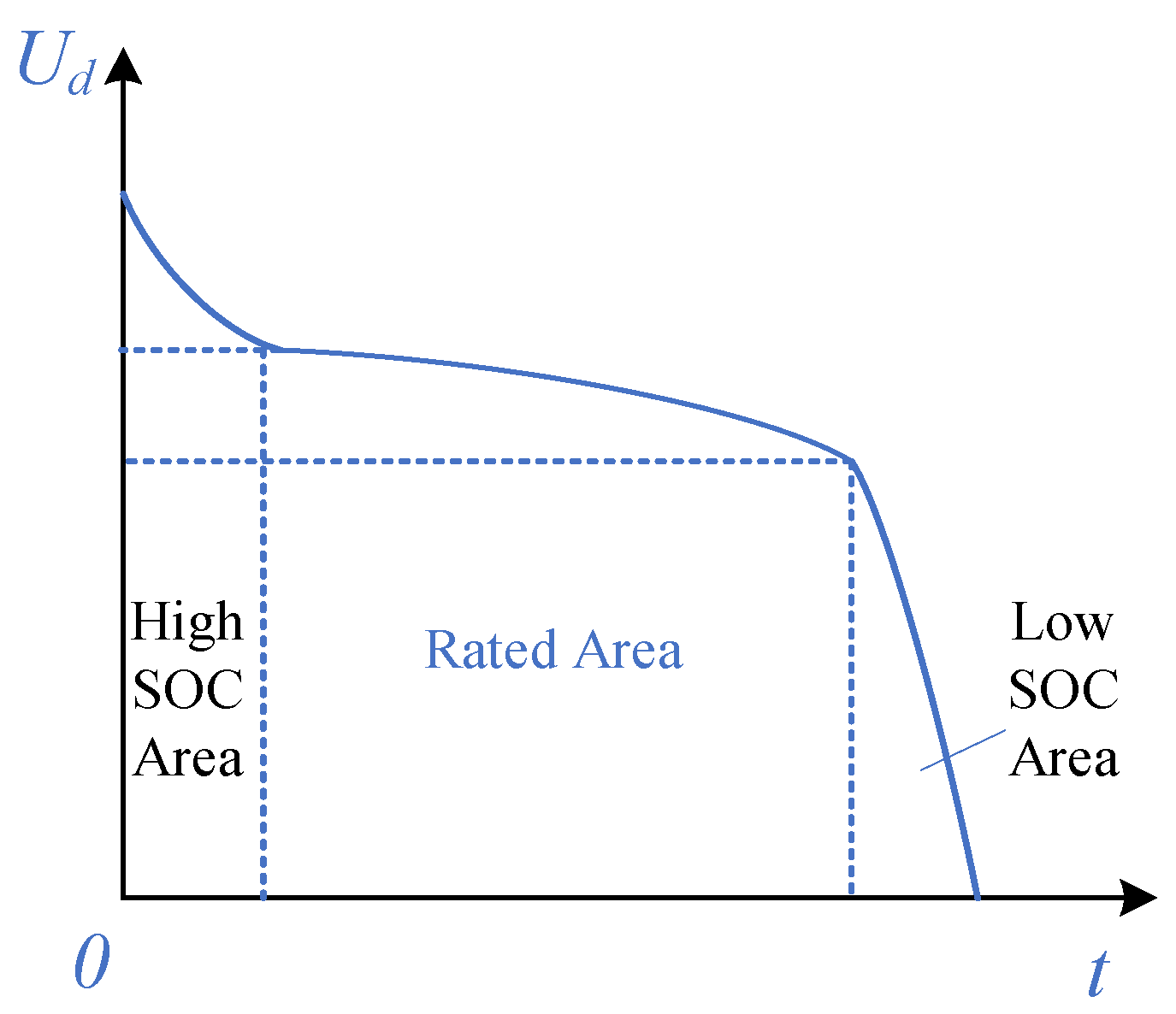
15]. The Thevenin model is mainly used for dynamic analysis of simple battery systems. The fourth-order model has a deeper physical meaning and is more complex, making it suitable for practical simulation analysis of larger battery systems. Based on the actual requirements of this article, we establish a simpler and more easily obtainable model and fit the actual equivalent circuit model based on the constant current discharge characteristic curve of the battery pack. The constant current discharge characteristic curve of the battery pack is shown in
Figure 1.
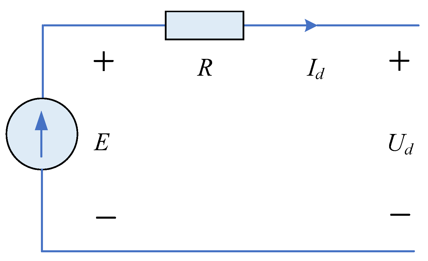
According to the above figure, the initial voltage rapidly decreases in the high-SOC area and enters the rated operating zone in a short period of time. A longer rated characteristic zone can ensure that the battery maintains a longer lifespan during use. As the discharge period approaches, the terminal voltage of the battery rapidly decreases in a short period of time. By fitting the constant current discharge characteristic curve of the battery, an equivalent circuit model can be obtained, as shown in
Figure 2.
From the above figure, it can be seen that the circuit model of the battery can be represented as a series structure of voltage source
E and equivalent internal resistance
R. The equivalent internal resistance
R is determined by the manufacturer at the time of production and remains unchanged during operation. The controlled voltage source
E can be represented as:
In the formula, E0 represents the potential within the battery system, A, K and B respectively represent fitting parameters, Aexp(−BQc) represents the initial discharge characteristics of the battery, Qc represents the discharge capacity and Cmax represents the maximum battery capacity.
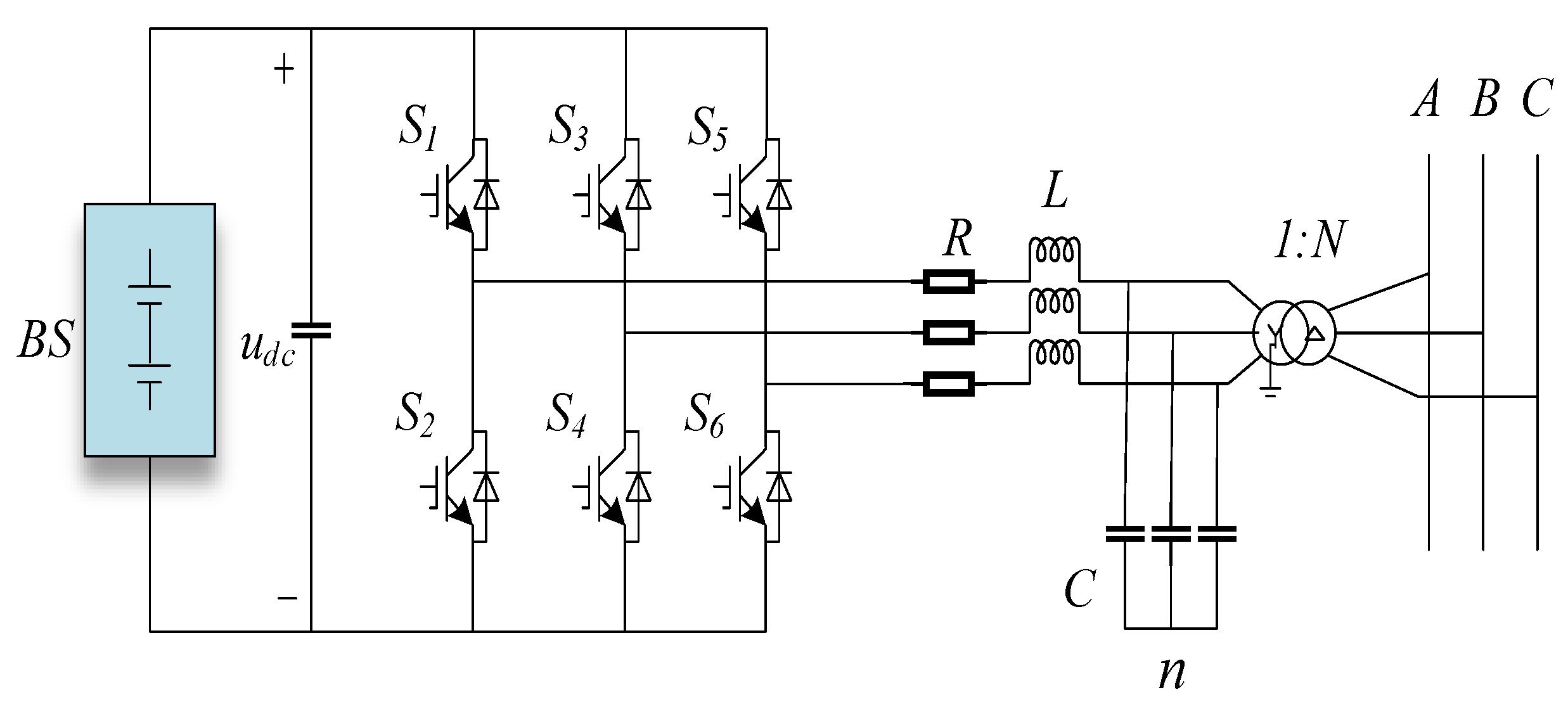
At present, the main power conversion system models include DC/AC–DC/DC hybrid connections or DC/AC direct connections. This paper uses the DC/AC direct connection type for study.
The structure diagram of the DC/AC direct connection type is shown in
Figure 3. This structure connects the battery system to the PWM converter and directly connects to the power grid through a step-up transformer, which plays a role in matching the voltage and isolation. This type of power conversion system has a simple structure and is suitable for various distributed independent system grid connection processes as it has lower energy consumption during charging and discharging processes.
2.2. The Structure of Wind Power System
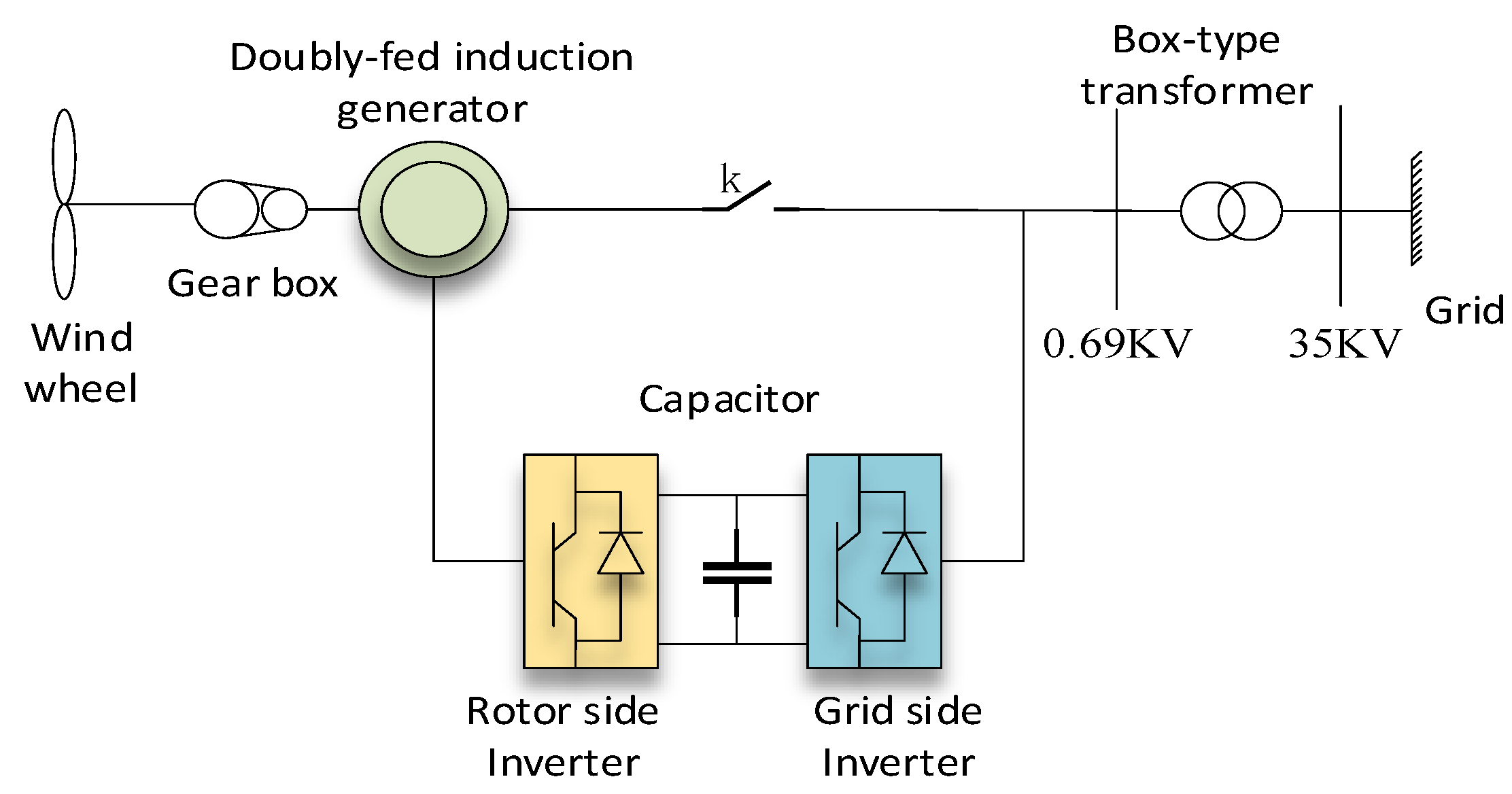
Wind power generation is achieved by converting wind energy into mechanical energy to drive the motor to rotate and output alternating current. Doubly fed induction generators (DFIGs) are currently the most widely used wind turbines in the world, with electrical structures including stator and rotor windings, as well as back-to-back PWM converters on the rotor windings. Its mechanical structure includes wind turbines, generators, directional controllers and other internal functional modules, such as a yaw system, electronic controller, hydraulic system and pitch system [
16].
The DFIG mainly consists of wind turbine blades, a gearbox, a doubly fed generator, a back-to-back PWM converter, etc., as shown in
Figure 4. The doubly fed fan maintains voltage stability at the fan outlet through the control system on the stator and rotor sides. When the parameters at the fan outlet match the system parameters, the switch k is closed and the fan is smoothly integrated into the system.
As for the type of the turbine for wind power, this paper uses horizontal axis wind turbines with variable pitch ability. The use of variable pitch technology in wind turbines can greatly improve the stress conditions of the blades and the entire machine, which is very beneficial for large wind turbines.
The three-phase stator winding voltage equations, three-phase rotor winding voltage equations and the flux linkage equations of the DFIG are as follows.
In the above equations, Us and Ur represent the stator and rotor voltages, respectively; Rs and Rr represent the stator and rotor resistance, respectively; Is and Ir represent the stator and rotor currents, respectively; Ψs and Ψr represent the stator and rotor flux linkages, respectively; Ls, Lr and Lm represent the self-inductance of stator and rotor and the mutual inductance between stator and rotor, respectively; and ωN and ωslip represent the rated speed and speed difference, respectively.
4. Case Study
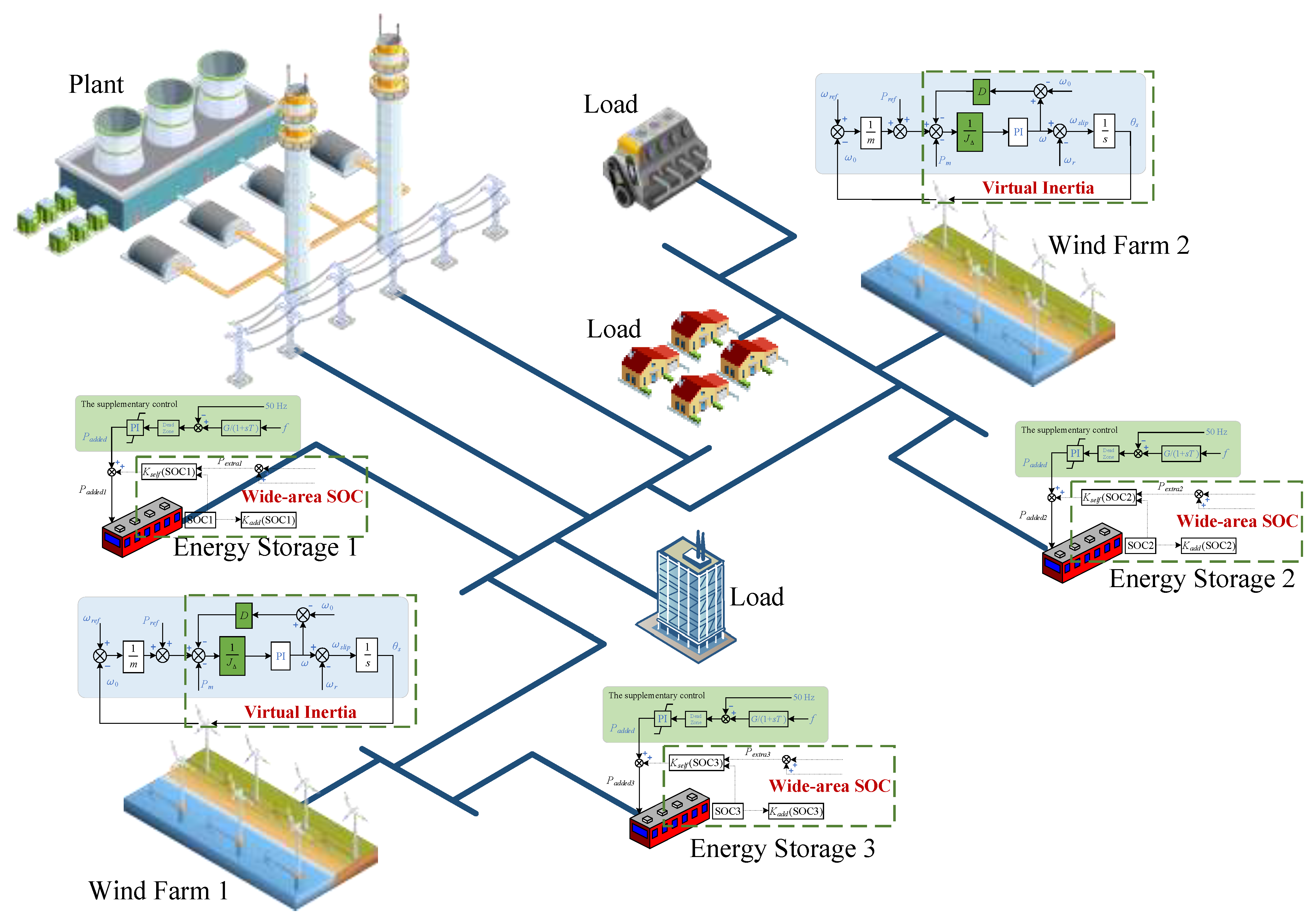
To verify the previously proposed coordination scheme, case studies are implemented in this section. The topology of the test model is presented in
Figure 9. It can be seen that there are three battery energy storage systems, two wind farms, one equivalent generator and some loads. The parameters of the system can be found in
Table 1.
The simulations are implemented in three different conditions. In the first condition, a 2100 MW load is put in at 4 s and no supplementary control is added. In the second condition, when the 2100 MW load is put in at 4 s, the virtual synchronous control of the wind farm and the traditional supplementary control of energy storage systems are added, which is named as the traditional control. In the third condition, when the 2100 MW load is put in at 4 s, the virtual synchronous control of the wind farm and the supplementary control considering wide-area SOCs of energy storage systems are added, which is named as the proposed control. All the loads mentioned above are fixed-type loads, and the load variation is achieved by increasing the load parameters when simulations are implemented.
Figure 10,
Figure 11,
Figure 12,
Figure 13,
Figure 14,
Figure 15,
Figure 16,
Figure 17 and
Figure 18 show the simulation results of different signals, which will be analyzed and compared in the next sections.
4.1. The Energy Storage System Simulation Results with No Additional Control
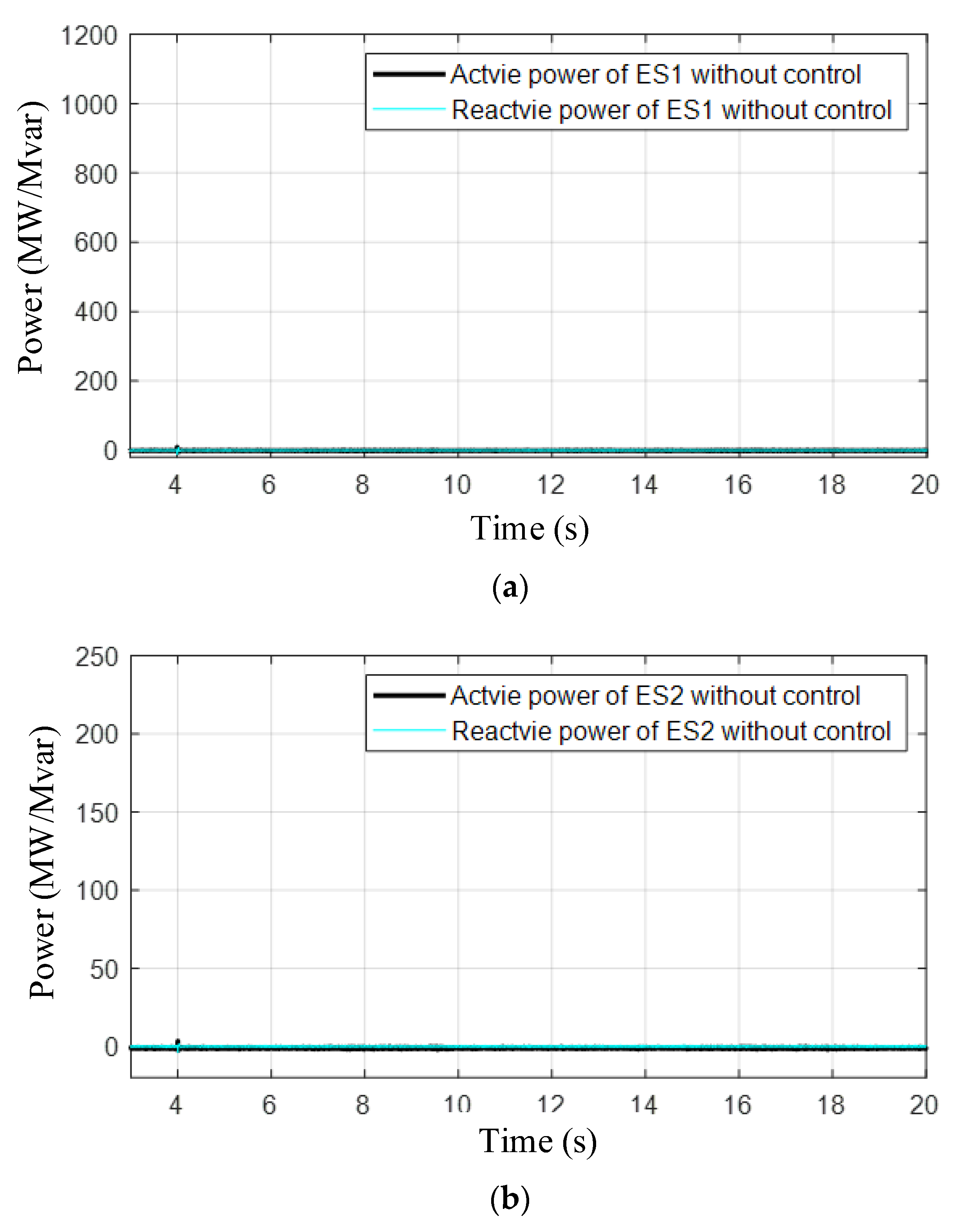
In
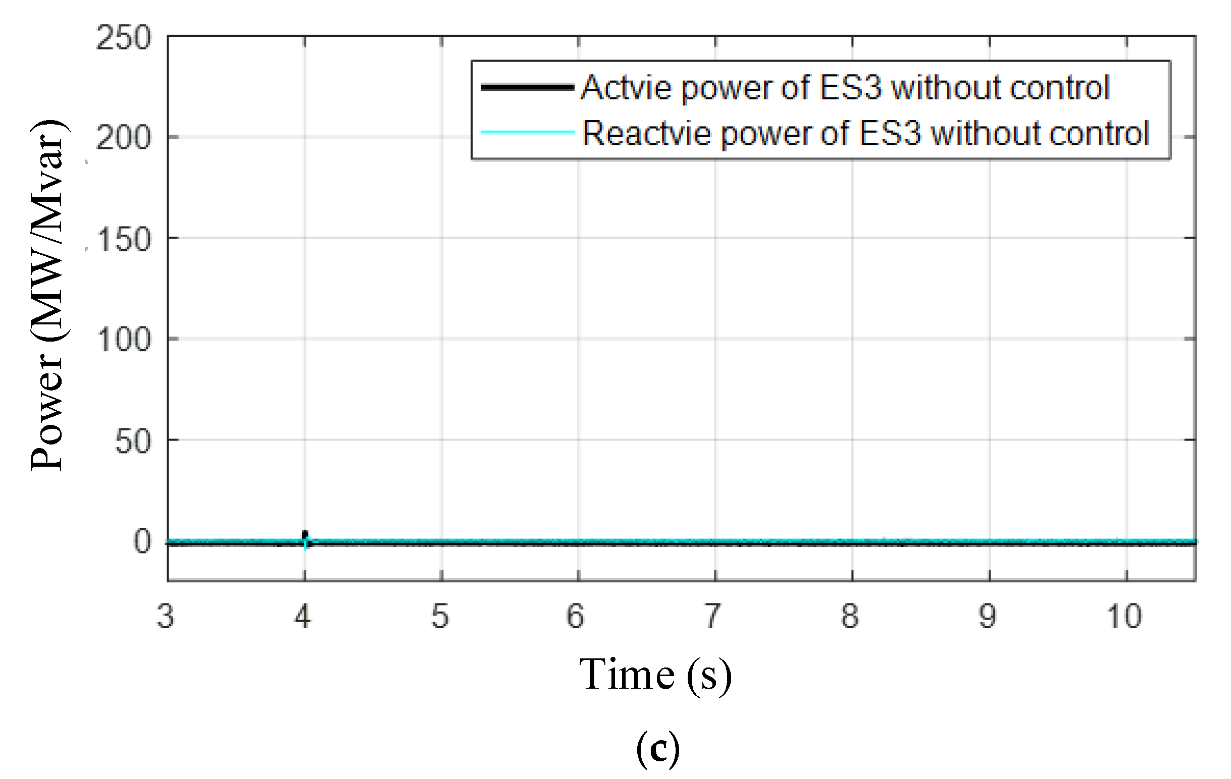
Figure 10, the output active and reactive power of energy storage system 1 (ES1), energy storage system 2 (ES2) and energy storage system 3 (ES3) are presented.
Figure 10 shows the results with no additional control, and it can be seen that the output of each energy storage remains zero. In addition, the equivalent SOC of each energy storage system does not change as no output is generated, which can be seen in
Figure 11. The equivalent SOC here is used because the real SOC varies in hours, which cannot be simulated in electromagnetic transient software. The discharging characteristics of the batteries are modified to ensure that the SOC can change in seconds. This modification is acceptable and convenient for analysis.
Figure 10.
The output active and reactive power of different energy storage systems when no additional control is added. (a) The output of ES1 without control. (b) The output of ES2 without control. (c) The output of ES3 without control.
Figure 10.
The output active and reactive power of different energy storage systems when no additional control is added. (a) The output of ES1 without control. (b) The output of ES2 without control. (c) The output of ES3 without control.
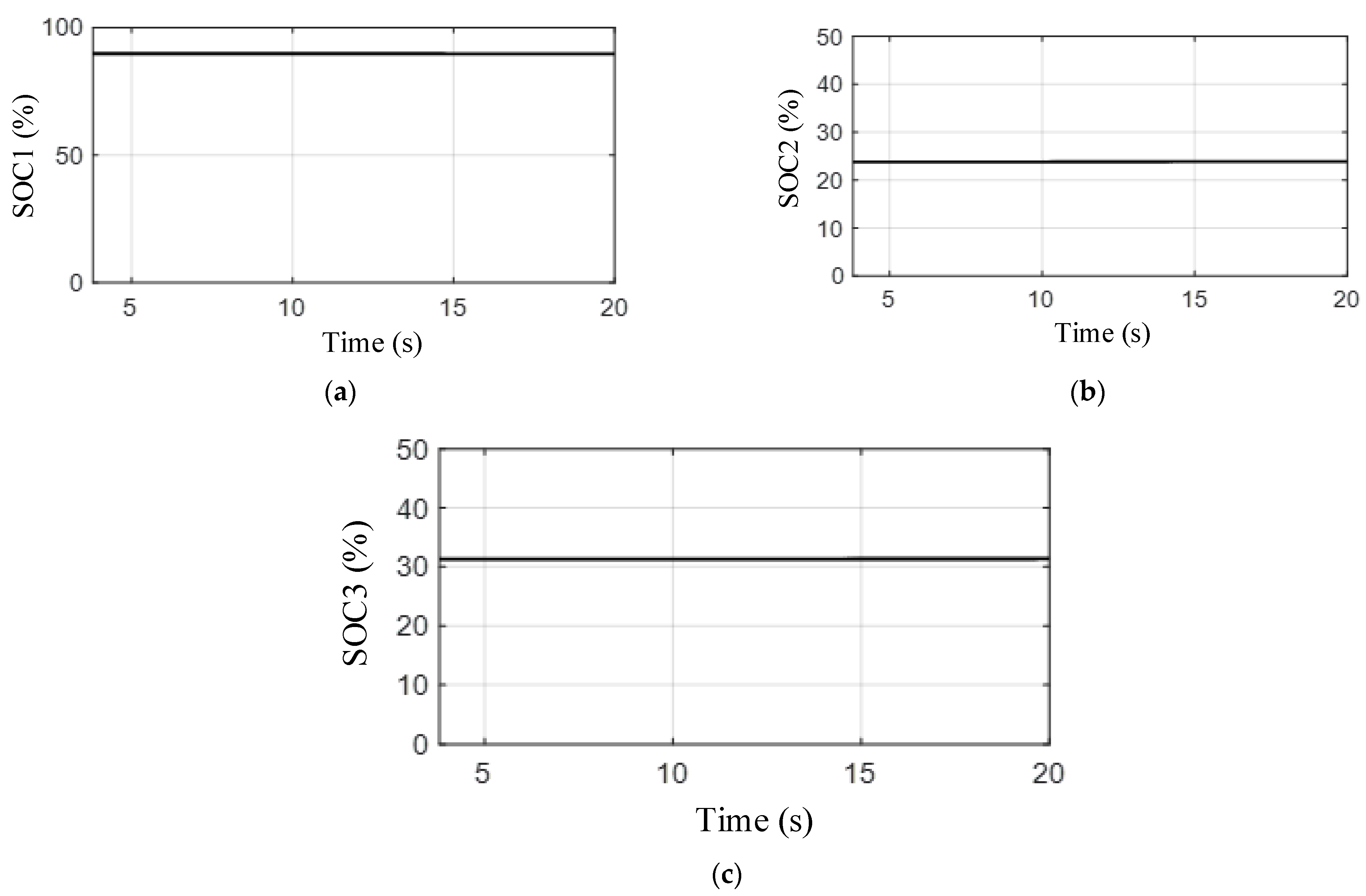
Figure 11.
The equivalent SOCs of different energy storage systems when no additional control is added. (a) The equivalent SOC of ES1 without control. (b) The equivalent SOC of ES2 without control. (c) The equivalent SOC of ES3 without control.
Figure 11.
The equivalent SOCs of different energy storage systems when no additional control is added. (a) The equivalent SOC of ES1 without control. (b) The equivalent SOC of ES2 without control. (c) The equivalent SOC of ES3 without control.
4.2. The Energy Storage System Simulation Results with Traditional Control
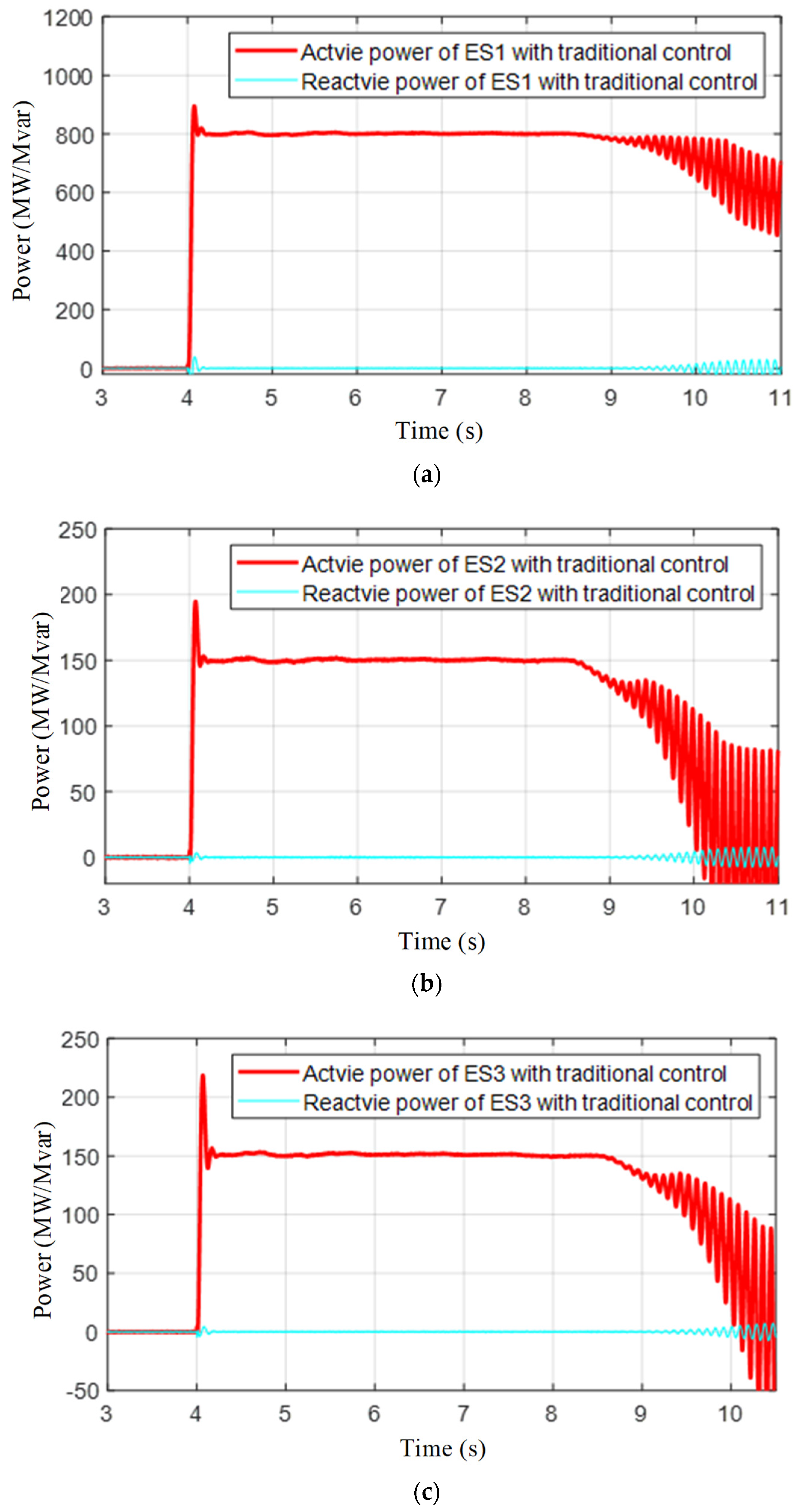
In
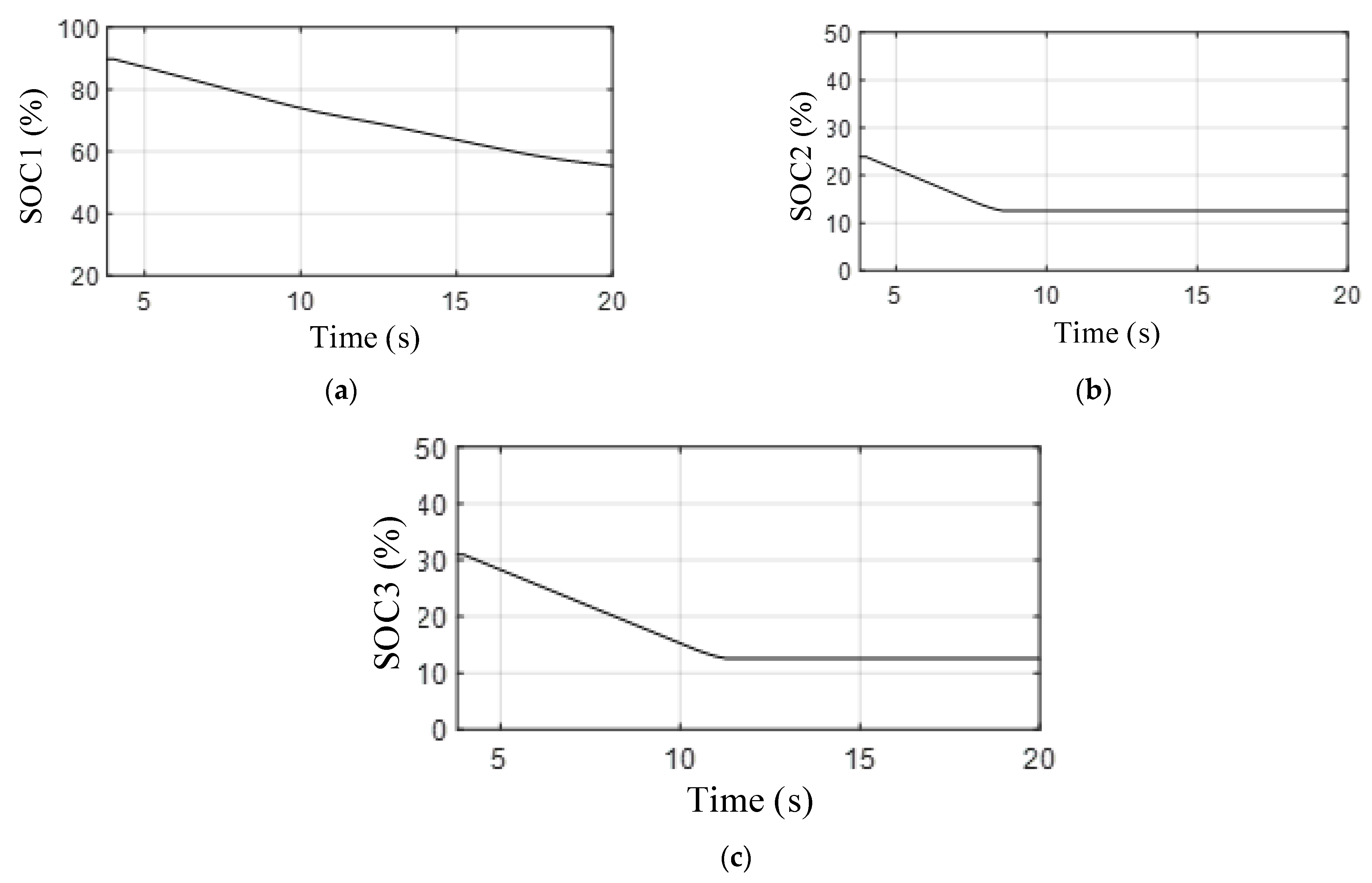
Figure 12, the output active and reactive power of energy storage system 1 (ES1), energy storage system 2 (ES2) and energy storage system 3 (ES3) are presented when traditional supplementary control is added. It can be seen that the outputs begin to oscillate after a while. This is because the traditional control does not consider the SOCs of the other battery storage systems. According to
Figure 13, ES2 and ES3 decrease to a relative low value (12%), the output of the battery becomes less and the system has no other support, meaning that oscillation occurs.
Figure 12.
The output active and reactive power of different energy storage systems when only traditional control is added. (a) The output of ES1 with traditional control. (b) The output of ES2 with traditional control. (c) The output of ES3 with traditional control.
Figure 12.
The output active and reactive power of different energy storage systems when only traditional control is added. (a) The output of ES1 with traditional control. (b) The output of ES2 with traditional control. (c) The output of ES3 with traditional control.
Figure 13.
The equivalent SOCs of different energy storage systems when only traditional control is added. (a) The equivalent SOC of ES1 with traditional control. (b) The equivalent SOC of ES2 with traditional control. (c) The equivalent SOC of ES3 with traditional control.
Figure 13.
The equivalent SOCs of different energy storage systems when only traditional control is added. (a) The equivalent SOC of ES1 with traditional control. (b) The equivalent SOC of ES2 with traditional control. (c) The equivalent SOC of ES3 with traditional control.
4.3. The Energy Storage System Simulation Results with the Proposed Control
In
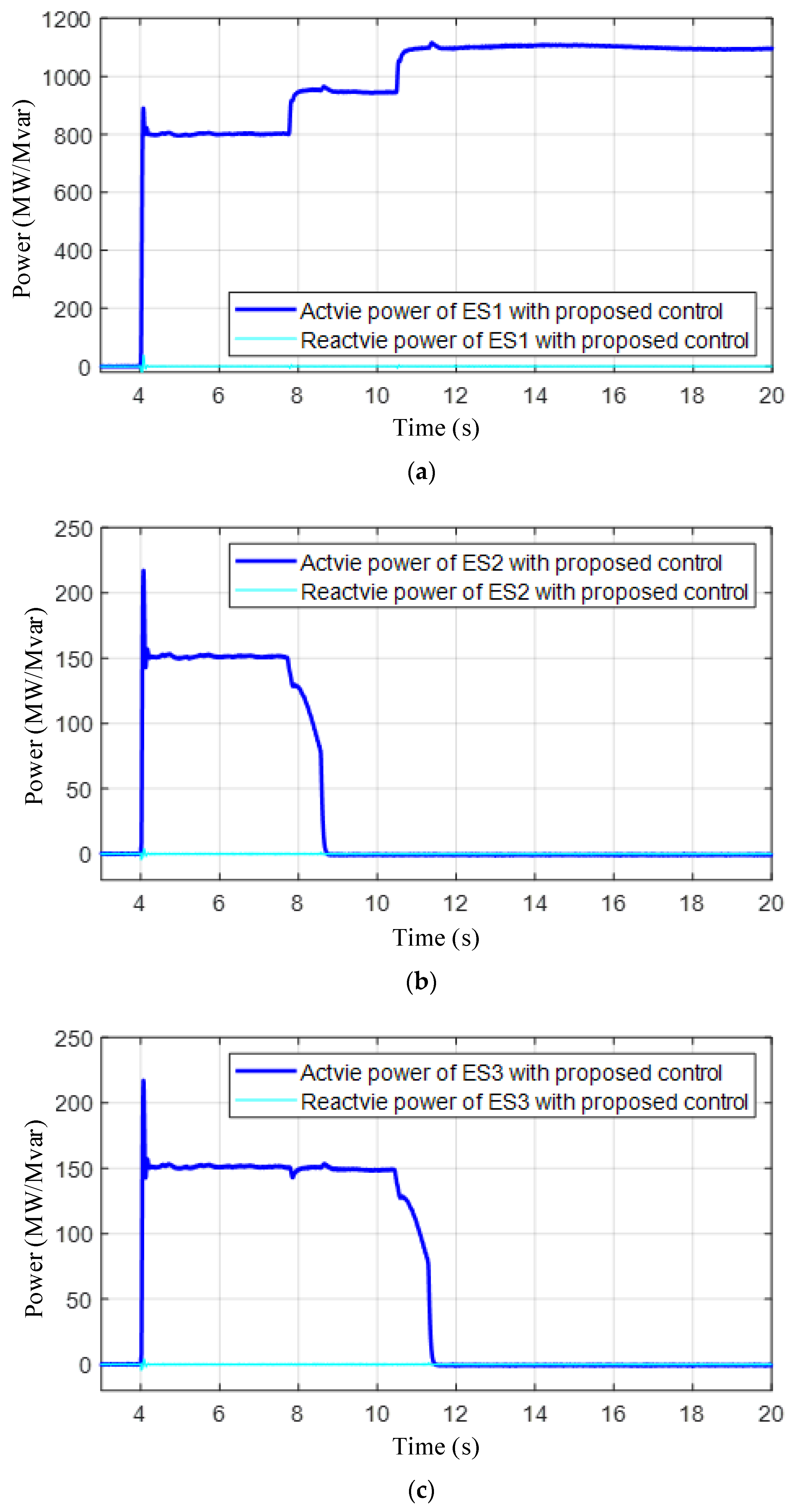
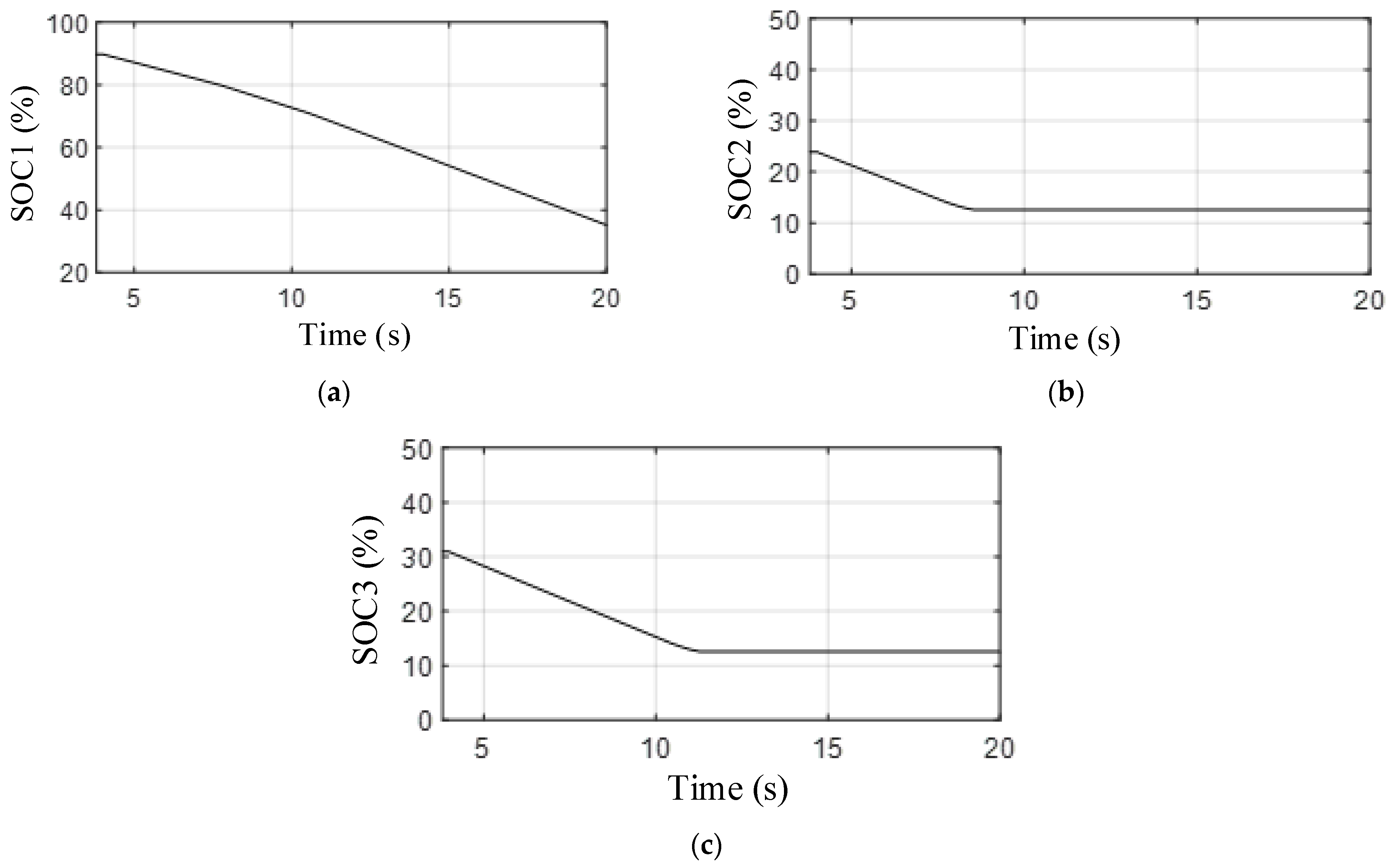
Figure 14, the output active and reactive power of energy storage system 1 (ES1), energy storage system 2 (ES2) and energy storage system 3 (ES3) are presented when the proposed control is added. It can be seen that the outputs of ES1 increase accordingly when the other battery’s SOC reaches low value. Additionally, the system can remain stable as the active power can be compensated.
Figure 15 shows the SOCs of each energy storage system.
Figure 14.
The output active and reactive power of different energy storage systems when the proposed control is added. (a) The output of ES1 with the proposed control. (b) The output of ES2 with the proposed control. (c) The output of ES3 with the proposed control.
Figure 14.
The output active and reactive power of different energy storage systems when the proposed control is added. (a) The output of ES1 with the proposed control. (b) The output of ES2 with the proposed control. (c) The output of ES3 with the proposed control.
Figure 15.
The equivalent SOCs of different energy storage systems with the proposed control. (a) The equivalent SOC of ES1 with the proposed control. (b) The equivalent SOC of ES2 with the proposed control. (c) The equivalent SOC of ES3 with the proposed control.
Figure 15.
The equivalent SOCs of different energy storage systems with the proposed control. (a) The equivalent SOC of ES1 with the proposed control. (b) The equivalent SOC of ES2 with the proposed control. (c) The equivalent SOC of ES3 with the proposed control.
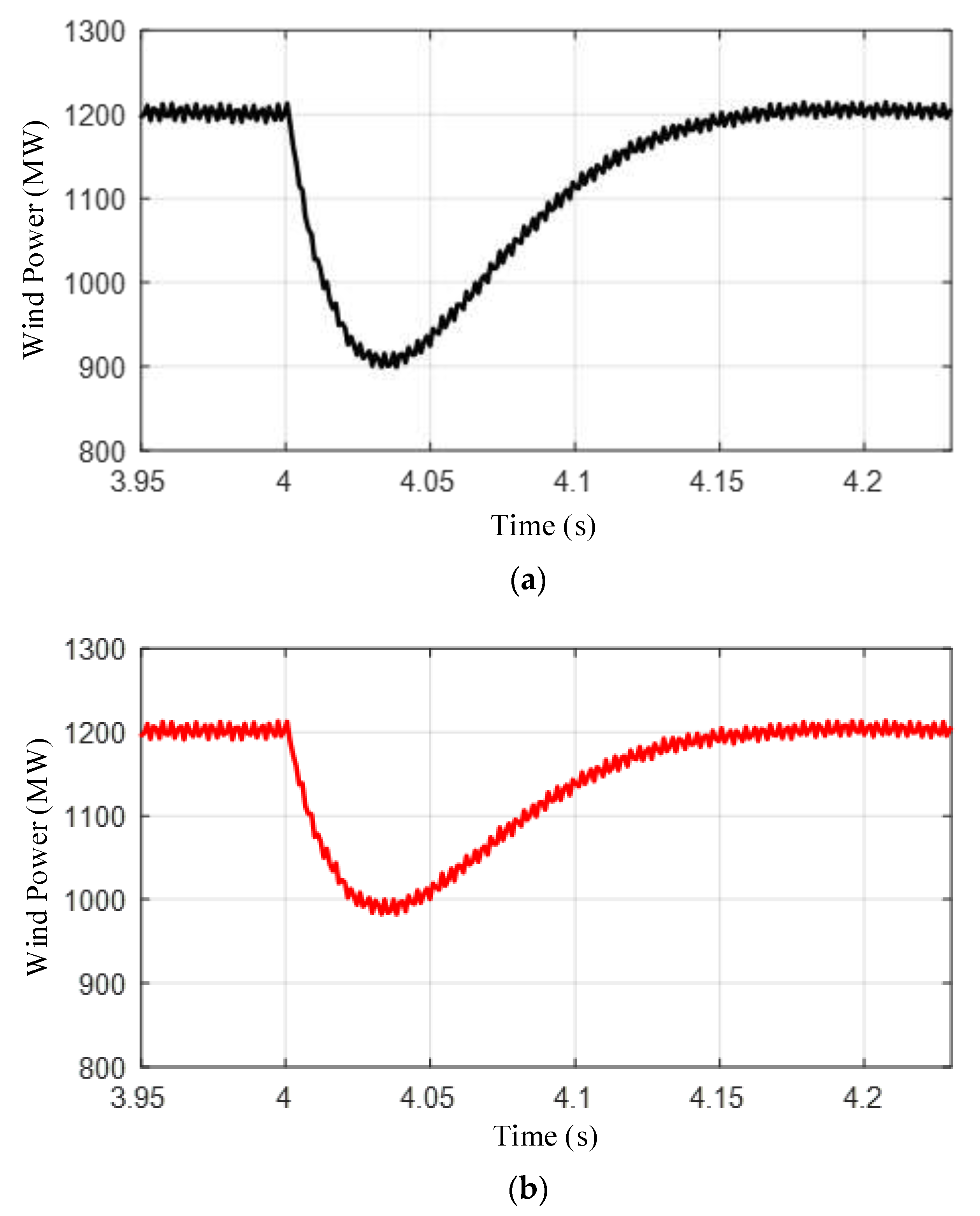
Figure 16 presents the output of the wind power with and without virtual synchronous control. It can also be seen that the virtual synchronous control can make the wind power output a more active power so that the system can be more stable.
Figure 16.
The output of the wind power with different controls. (a) The wind power without virtual synchronous control. (b) The wind power with virtual synchronous control.
Figure 16.
The output of the wind power with different controls. (a) The wind power without virtual synchronous control. (b) The wind power with virtual synchronous control.
4.4. The AC Frequency Comparison in Different Control Conditions
From the above simulation results, it can be seen that the proposed method can generate more active power. This next section compares the AC side frequency with different control modes, which also proves the effectiveness and correctness of the proposed strategy.
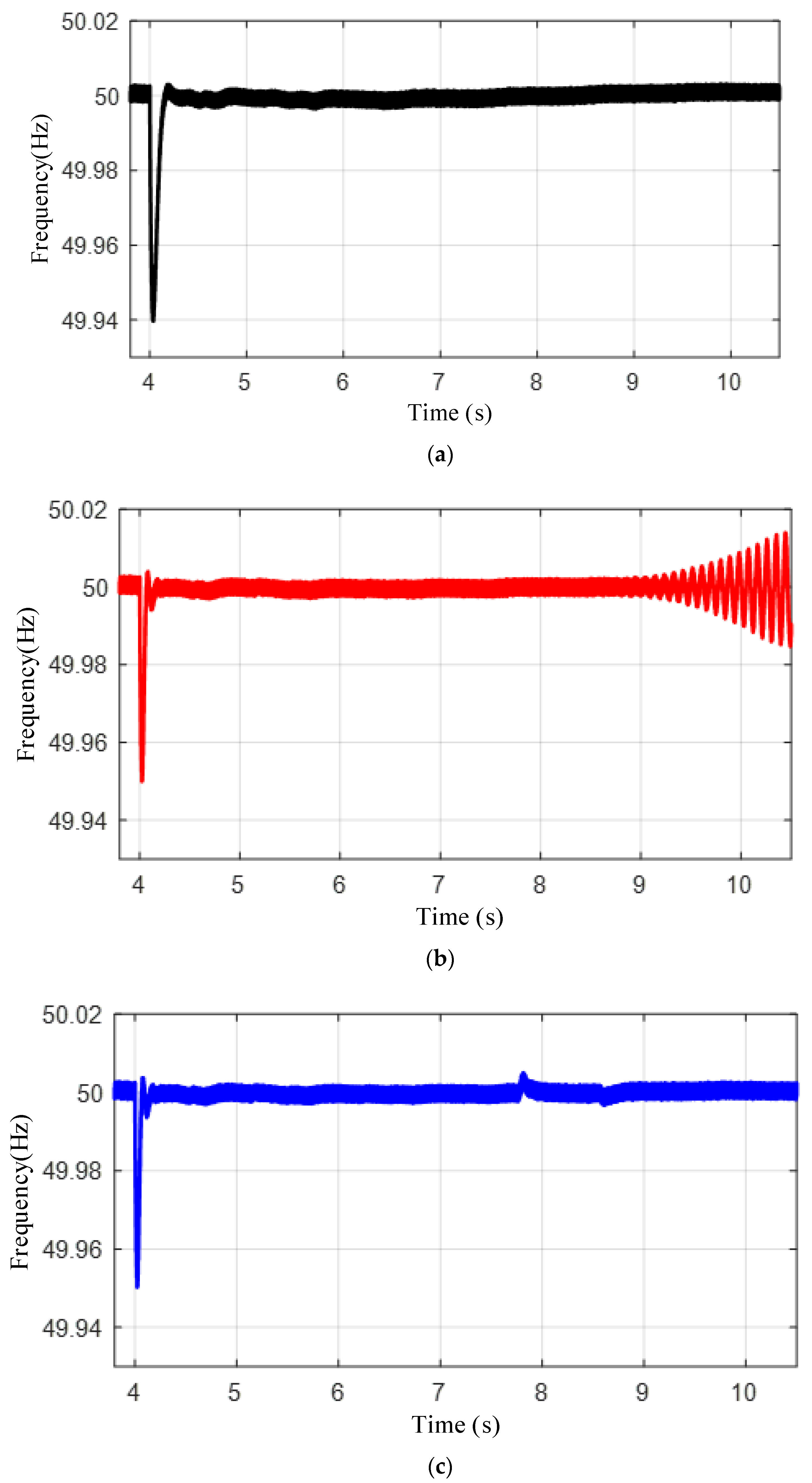
In
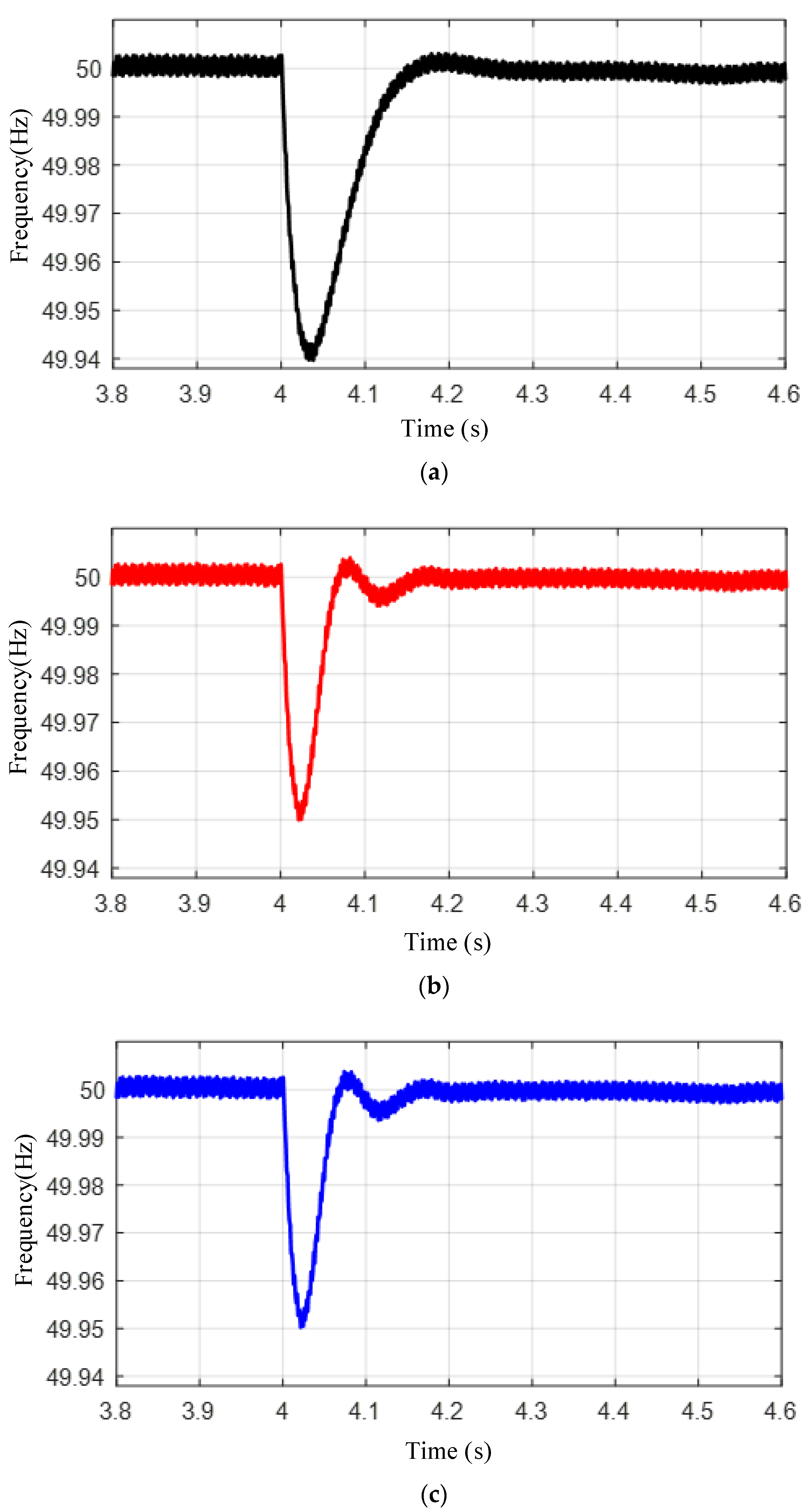
Figure 17, it can be seen that in the transient 3.8 s and 4.6 s, the frequency disturbance can be decreased when additional controls are added, where about 0.01 Hz of fluctuation can be avoided. Moreover, the frequency can also recover faster. However, according to
Figure 17, there is no difference between the proposed control and the traditional control in the transient period. Such a problem is addressed in
Figure 18.
Figure 17.
The AC system frequency disturbance in case 1 simulation between 3.8 s and 4.6 s. (a) The frequency disturbance without control. (b) The frequency disturbance with traditional control. (c) The frequency disturbance with the proposed control.
Figure 17.
The AC system frequency disturbance in case 1 simulation between 3.8 s and 4.6 s. (a) The frequency disturbance without control. (b) The frequency disturbance with traditional control. (c) The frequency disturbance with the proposed control.
In
Figure 18, the frequencies in different conditions are shown in a relatively long period, namely 20 s. It can be observed that with traditional control the system finally becomes unstable, whereas the proposed strategy can keep the frequency maintained at the rated value.
The oscillations occur because the AC system with converters is actually not so strong and the active power and the reactive power impact each other extensively. Once the disturbance occurs, the traditional control cannot generate more active power, making the AC side and the DC side both suffer from the power imbalance, which finally makes the storage oscillate and then causes the AC system to also become unstable. Compared with the no additional control and traditional control methods, the proposed strategy cannot only enhance the transient stability but also ensure the steady-state stability.
Figure 18.
The AC system frequency disturbance in case 1 simulation between 3.8 s and 20 s. (a) The frequency disturbance without control. (b) The frequency disturbance with traditional control. (c) The frequency disturbance with the proposed control.
Figure 18.
The AC system frequency disturbance in case 1 simulation between 3.8 s and 20 s. (a) The frequency disturbance without control. (b) The frequency disturbance with traditional control. (c) The frequency disturbance with the proposed control.


