Article

Coordinated Voltage-Power Control for DC Distribution Networks Based on an Uncertainty and Disturbance Estimator

1
Xuefeng Mountain Energy Equipment Safety National Observation and Research Station, Chongqing University, Shapingba District, Chongqing 400044, China
2
State Grid Sichuan Economic Research Institute, Chengdu 610041, China
*
Author to whom correspondence should be addressed.
Electronics 2023, 12(14), 3137; https://doi.org/10.3390/electronics12143137
Submission received: 24 June 2023 / Revised: 16 July 2023 / Accepted: 18 July 2023 / Published: 19 July 2023

Abstract

:
DC distribution networks are low-inertia systems with a range of uncertainties and disturbances. The traditional droop control widely used in DC distribution networks has a contradiction between the accurate power sharing of power units and voltage deviation due to the presence of line impedance. To overcome this contradiction and enhance the immunity and tracking performance of voltage-source converter (VSC) current inner loop PI control, this paper proposes a coordinated voltage-power control strategy based on an uncertainty and disturbance estimator (UDE) for DC distribution networks. Firstly, the improved droop control strategy based on the UDE is proposed, which not only avoids the influence of line impedance on the load current sharing, but also achieves voltage stabilization at the set value. Secondly, an improved VSC current inner loop controller based on the UDE is designed to improve the VSC’s tracking performance for the droop output reference value. The UDE control theory is applied to estimate and compensate for the uncertainties and disturbances of the VSC current inner loop control, in order to improve the tracking and immunity of the VSC current inner loop and enhance the DC voltage robustness. Finally, a three-terminal DC distribution network is taken as an example to verify the effectiveness of the proposed strategy.

1. Introduction

In recent years, with the shortage of traditional energy and the booming development of power electronics technology, DC distribution networks have attracted wide attention because of their high efficiency in accessing distributed energy sources and ability to connect with AC distribution networks via a voltage-source converter (VSC) to form a multi-terminal distribution system. The most basic requirement for developing a DC distribution network is to ensure the power balance in the system, which can be reflected by the stability of the DC voltage. However, the system parameters’ uncertainties, external disturbances, and converter station switching will affect the stability of this DC voltage [1,2]. Therefore, considering the multiple uncertainties and disturbances to which the system is subjected, designing a practical control strategy to reasonably share the current of each power unit while ensuring the DC voltage stability is the key to the safe and stable operation of the DC distribution network [3].
Compared to AC distribution networks, DC distribution networks do not involve frequency control and instead focus solely on voltage control. There are three primary voltage control methods for DC distribution networks: droop control, distributed control, and concentrated control [4]. Among these, droop control adjusts the relationship between the DC voltage and current through negative slope characteristics to realize the real-time control of the system power balance, which is a differential regulation. It has been widely used in DC distribution networks [5,6,7]. However, the line impedance impacts the droop coefficient, which will affect the output voltage of each converter station and the reasonable sharing of the system’s load current among them [8]. This is a core problem to be solved in the study of the coordinated control of DC distribution networks. In [9], an adaptive PI controller was used to adjust the droop resistance to eliminate the current sharing error of each power unit in the DC distribution network, but it did not provide voltage restoration. The authors in [10] proposed a secondary control strategy suitable for the DC microgrid to solve the contradiction between the voltage deviation and current sharing accuracy. The authors in [11] put forward two methods: variable droop coefficient and voltage restoration, which achieved the DC bus’s voltage stability and accurate power sharing. In [12], an adaptive compensation strategy based on fuzzy control was proposed to precisely distribute the power while achieving voltage compensation. The authors in [13] proposed a dynamic droop coefficient correction control strategy to achieve precise current sharing. The improved droop control methods mentioned above have achieved specific control effects by improving these droop coefficients, but they have not reduced the uncertainties and disturbances of the DC distribution network, which is still a small inertia system with modeling and parameter errors, system faults, and other uncertainties and disturbances. Therefore, the study of coordinated control to achieve accurate power sharing and voltage stability while enhancing the immunity of the system’s voltage is an important direction for droop control improvement.
In the DC distribution network, the quality of the voltage operation is not only related to the droop control strategy between the converter stations, but also to each source converter’s operating performance. Because the output voltage of the droop control is used as the input reference value of each source converter, the precise load current sharing is finally realized through the voltage current dual-loop control of the VSC. The VSC generally adopts voltage and current dual-loop Proportional Integral (PI) control, which can theoretically achieve a zero steady-state error tracking effect [14]. However, the PI control is sensitive to the uncertainty of the system parameters and external disturbances, and its tuning process is tedious [15], which will affect the stability of the DC bus voltage. To effectively regulate the DC bus voltage, the current inner loop robust control in dual-loop control has been studied in many kinds of literature. In [16], a current loop based on adaptive PI was proposed to eliminate the influence of system parameter disturbance on the DC bus voltage and improve the system’s adaptability. In [17], a time-delay compensation method based on a second-order generalized integrator was applied to the current inner loop to reduce the system’s sensitivity to parameter variations, thus improving the system’s immunity. The authors in [18] applied a proportional resonant regulator to achieve a good tracking performance of the current inner loop control. However, the above methods still have problems, such as complicated algorithms and tedious parameter tuning.
In [19], a UDE-based controller was proposed. This UDE-based controller was based on the assumption that an unknown continuous band-limited signal can be estimated and used to synthesize a practical robust controller by using appropriate filters, which has two degrees of freedom characteristics between the anti-disturbance and tracking performance. The UDE-based control method can quickly estimate and compensate for system uncertainty dynamics and external disturbances and have an excellent robust control performance, which has been successfully applied to many systems, such as uncertain systems, nonlinear systems, and time-varying systems [20,21]. The literature [22,23] applied the UDE control method to the current control of a paralleled inverter and a permanent-magnet synchronous motor, respectively, which achieved power sharing independent of the output impedance and improved the current tracking and immunity of the controller. In [24], a UDE-based controller was designed to improve the immunity of the inverter according to its characteristics. Meanwhile, the controller parameters were simplified to filter parameters and had decoupling characteristics.
Driven by the previously mentioned motivations and advantages offered by the UDE control method, it is feasible to apply the UDE control theory to improve the stability of the DC distribution network. This paper proposes a voltage-power coordinated control strategy based on a UDE for the DC distribution network to enhance its voltage stability and current sharing accuracy, as well as the immunity and tracking performance of the VSC current inner loop PI control. The controller structure contains the improved droop control strategy and improved VSC current inner loop controller, which is depicted in Figure 1. Figure 1 illustrates the DC distribution network, divided into three regions: the first region connects the AC grid to the DC system through VSC1, VSC2, and VSC3. These converters rectify the AC power and form the interface between the AC and DC systems. In this region, the traditional droop control or the proposed voltage-power coordinated control is used to share the converter’s output current to maintain the DC bus’s voltage stability. The second region is the photovoltaic (PV) module connected to the DC bus through the boost converter, which adopts the traditional PI control. The third region is the passive load.
The main contributions of this paper are summarized as follows.
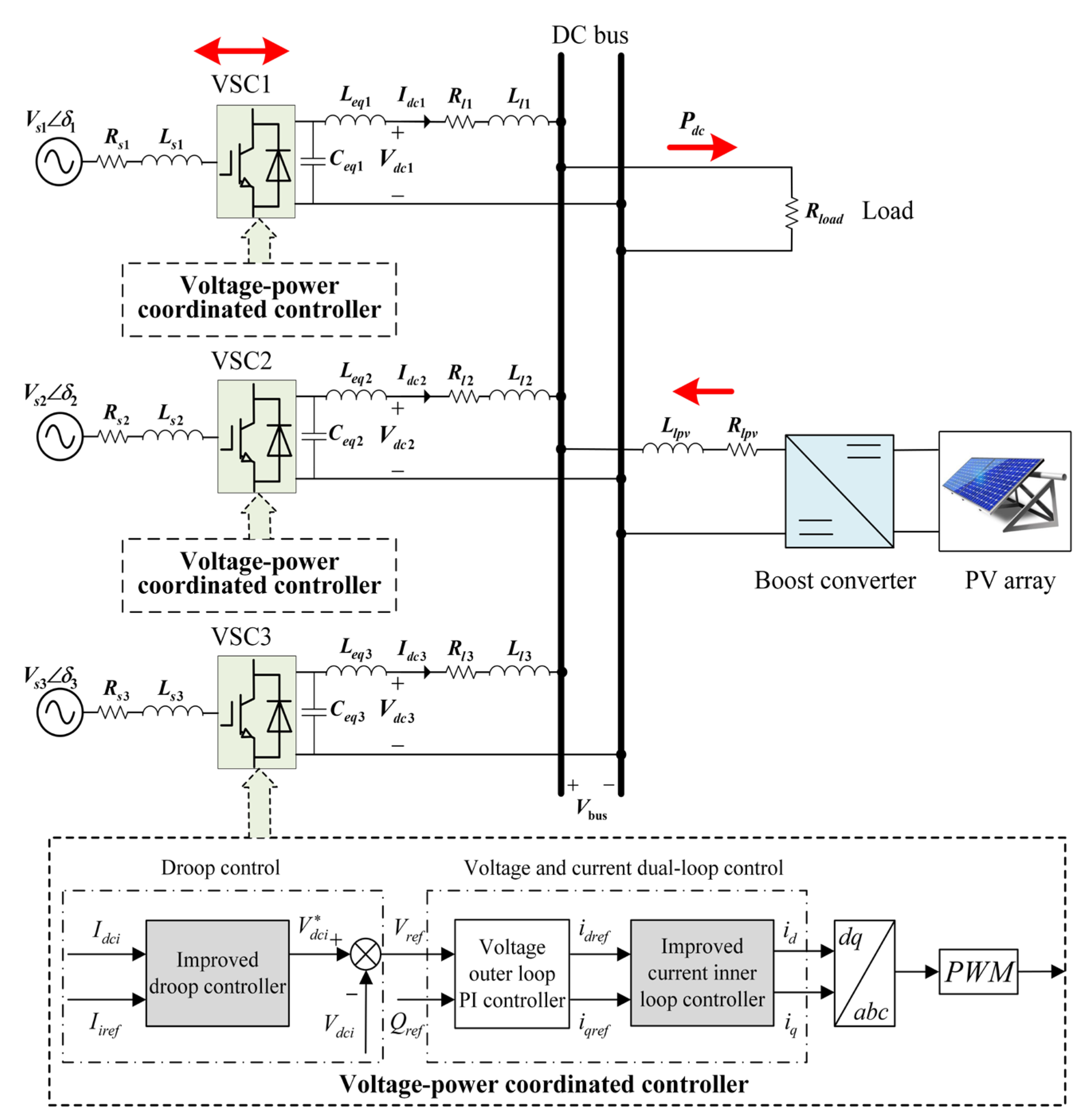
  • Aiming at the contradiction between the DC voltage and the load current sharing of the converter stations under the traditional droop control due to the influence of line impedance, an improved droop control strategy based on the UDE control theory for the DC distribution network is proposed. Firstly, to realize the reasonable load current sharing of the converter stations, a load current reference model is designed by introducing the capacity ratio of the source converters. Secondly, to realize the voltage stability control of the DC distribution network, the output voltage characteristic of the droop control is designed with the control objective that the output current of the source converter can better track the reference current.
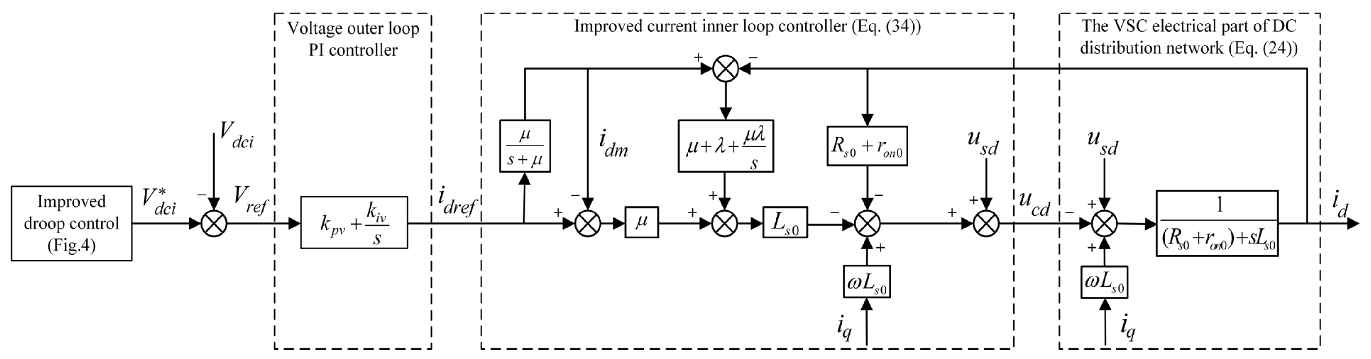
  • In order to improve the tracking performance of the VSC current inner loop and the robustness of the DC voltage, the VSC current inner loop controller based on a UDE is designed. Firstly, the state space model with disturbances and the desired reference model in the DC distribution network are established. Furthermore, the controller input variable is designed from the perspective that the model error tends to be zero to estimate and compensate for the effects of various disturbances on the controller. The final structure of the improved VSC current inner loop controller is obtained.
The remainder of this paper is organized as follows. Section 2 analyzes the contradiction of traditional droop control and proposes the UDE-based droop control method. In Section 3, the design process of the VSC current inner loop based on a UDE is presented. In Section 4, a simulation model of the three-source DC system shown in Figure 1 is built to verify the effectiveness of the proposed control strategy by simulating the operating conditions of the DC distribution network. Finally, the paper’s conclusion is provided in Section 5.

2. Design of the Improved Droop Control in the DC Distribution Network

Droop control is often used to realize the current sharing and voltage stability control among multiple source converters in the DC distribution network. This section first analyzes the contradiction between the voltage deviation and current sharing accuracy of traditional droop control. Secondly, to ensure that the DC bus voltage is stable under the set value and that the load current of each source converter can be accurately shared, the UDE control law is used to improve the droop control characteristics.

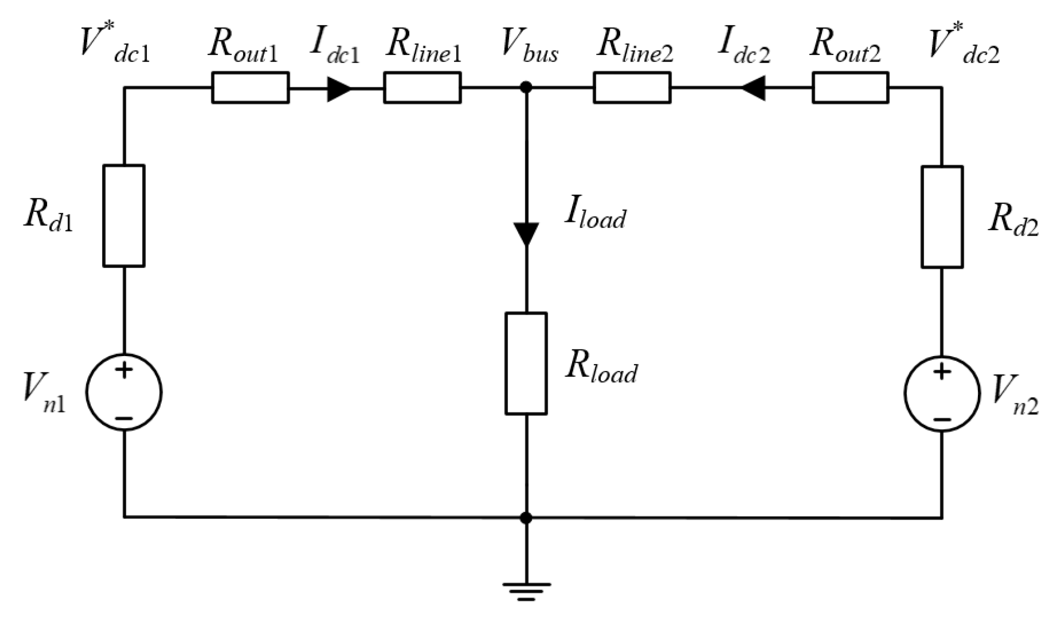
2.1. Analysis of Traditional Droop Characteristics of the DC Distribution Network

The dual-source single-load DC system shown in Figure 2 is used to analyze the influence of line impedance on the droop characteristics, where only the DC resistance is considered in the steady-state case. Moreover, the subscript i in the variables corresponds to 1 or 2, V n i is the output voltage setting value of the VSC when it is unloaded, V d c i * is the output voltage reference of the i-th VSC, I d c i is the output current of the VSC, and R d i means the droop coefficient. R o u t i is the equivalent output resistance of the VSC, R l i n e i is the DC line resistance, V b u s is the DC bus voltage, and I l o a d is the current flowing through the load.
From Figure 2, the typical droop control expression in the DC distribution network is:
V d c i * = V n i R d i I d c i
After considering the VSC output resistance and the DC line resistance, the equivalent droop coefficient becomes: R d i = R o u t i + R l i n e i + R d i . According to Kirchhoff’s law, the DC bus voltage is:
V b u s = V n i R d i I d c i = V n 1 R d 2 R d 1 + R d 2 ( I d c 1 + I d c 2 )
To make the converter station reasonably share the power of the DC system according to its rated capacity, the droop coefficient of the converters should satisfy [25]:
R d 1 R d 2 = P 2 P 1 = I d c 2 I d c 1 ,
where P 1 and P 2 are the rated output power of VSC1 and VSC2, respectively.
When the rated power of both converter stations is the same, there is: I d c 1 = I d c 2 , R d 1 = R d 2 . After considering R o u t i , R l i n e i , and R o u t 1 + R l i n e 1 R o u t 2 + R l i n e 2 , the load current sharing should satisfy:
I d c 1 I d c 2 = R d 2 R d 1 = R o u t 2 + R l i n e 2 + R d 2 R o u t 1 + R l i n e 1 + R d 1 1
From Equation (4), it can be seen that R o u t i and R l i n e i will lead to an error in the output power sharing of each converter station. According to Equations (2) and (4), the droop characteristic curves with different droop coefficients are shown in Figure 3 when V n i is unchanged. Curves ① and ③ correspond to VSC1, and curves ② and ④ correspond to VSC2.
In Figure 3, when the droop coefficient is small, the voltage deviation between the DC bus voltage and the set value is Δ V . Due to the different line resistances, VSC1 and VSC2 operate at two points, A and B, respectively, and the current sharing deviation between them is Δ I . When the droop coefficient increases, the DC bus’s voltage deviation is Δ V . VSC1 and VSC2 operate at two points, C and D, respectively, and their current sharing deviation is Δ I . It can be easily known from Figure 3 that Δ V > Δ V , Δ I < Δ I , so the voltage deviation will be larger and the current sharing deviation will be smaller as the droop coefficient increases.
Therefore, traditional droop control has contradictions between the voltage deviation and current sharing accuracy due to the DC line impedance. In addition, parameter variations, model mismatches, and system faults in the DC distribution network during its operation will impact the droop control. Next, this paper will improve the operational characteristics and immunity of the traditional droop control in DC distribution networks.

2.2. Design of the Improved Droop Control

2.2.1. Setting of Load Current Reference Value Considering the Capacity Ratio

In order to weaken the influence of the line impedance and improve the power-sharing accuracy and voltage quality of the DC distribution network, the capacity ratio of each source converter is introduced so that the load current reference value required for the UDE-based droop control is determined and expressed as follows:
I i r e f = I l o a d n s i V b u s V d c i * n d i ,
where I i r e f is the load current reference value of the i-th source converter and n d i is the droop coefficient of the i-th source converter, which is set in proportion to n s i . 1 / n s i is the capacity ratio of the i-th source converter, expressed as 1 / n s i = S i / k = 1 l S k , where S i is the capacity of the i-th source converter and k = 1 l S k is the sum of the capacities of all the source converters involved in the operation.
When the DC distribution network is operating under ideal conditions, it is hoped that V b u s = V d c i * . From Equation (5), the load current reference value of each branch is:
I i r e f = I l o a d / n s i
This implies that each branch’s load current reference value shares the actual total load current according to the capacity ratio.
When considering the influence of the VSC output impedance and line impedance, it is clear that there is V b u s V d c i * , implying that the DC system has voltage deviation. By introducing ( V b u s V d c i * ) to regulate I i r e f , this will eventually achieve V b u s approximating V d c i * through the subsequent control, which allows each branch’s load current reference value to share the actual total load current according to the capacity ratio.

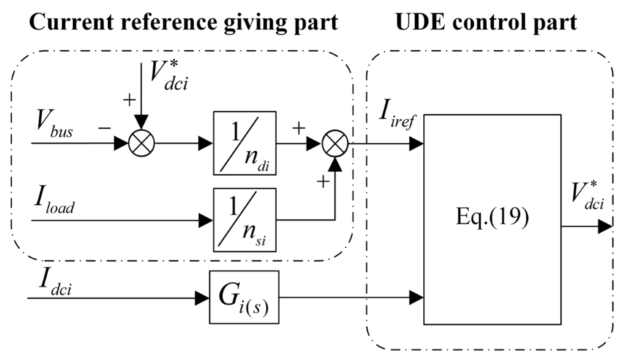
2.2.2. Design of the UDE-Based Droop Control

During the operation of DC distribution systems, the system is often affected by uncertainties and unpredictable disturbances. In order to improve the immunity of the droop control in DC distribution networks, a nonlinear single input and output system state model [21] with uncertainties and disturbances is defined as:
x ˙ ( t ) = a x ( t ) + b u ( t ) + d 0 ( t ) + σ ( t ) ,
where x ( t ) is the system state variable, u ( t ) is the control input variable, and a , b represent the state and control coefficients, respectively, which are non-zero constants. d 0 ( t ) is the known external disturbance variable and σ ( t ) is all the uncertainties and disturbances of the system, expressed as:
σ ( t ) = Δ a ( t ) x ˙ ( t ) + Δ b ( t ) x ( t ) + Δ c ( t ) u ( t ) + Δ r ( t ) d 0 ( t ) + f ( t ) ,
where Δ a ( t ) and Δ b ( t ) are the unknown state coefficients, Δ c ( t ) and Δ r ( t ) are the control coefficient and the external disturbance coefficient, respectively, and f ( t ) is the unknown disturbance variable.
The general expression for the load current of each source converter branch in the DC distribution network can be written as:
I d c i = V d c i V b u s Z o ,
where Z o is the total branch impedance, including the converter output impedance and line impedance, that is Z o = Z o u t + Z l i n e .
For the DC distribution network, the state variable is set to x ( t ) = I d c i and the control input variable is set to u ( t ) = V d c i . The known external disturbance variable is taken as d 0 ( t ) = V b u s Z o , and the system reference command is chosen as u m ( t ) = I i r e f . The corresponding uncertainties and disturbances of the parameters and models are described as:
f i = Δ Z o i Z o V d c i Δ Z o i Z o V b u s + d i ,
where Δ Z o i is the uncertainty and dynamic variation of the i-th converter branch’s impedance and d i is the known and unknown system disturbances.
I d c i is filtered by a low-pass filter to remove high-frequency uncertainty and interference when entering the UDE-based droop control part. The filter is defined as:
G i ( s ) = 1 1 + τ i s ,
where τ i is the time constant. After considering Equations (10) and (11), Equation (9) can be rewritten as:
I d c i = L 1 1 1 + τ i s 1 Z o V d c i 1 Z o V b u s + f i ,
where is the convolution symbol and L 1 is the Laplace inversion symbol.
Firstly, deriving Equation (12), and then according to Equation (7), the uncertain dynamic spatial state model of the load current of each source converter branch of the DC distribution network can be obtained as:
I ˙ d c i = 1 τ i Z o V b u s 1 τ i Z o V d c i + σ i ,
where σ i is the total uncertainty and disturbance of the DC distribution network, expressed as: σ i = f i I d c i τ i . Then, Equation (13) is further rewritten as:
σ i = I ˙ d c i 1 τ i Z o V b u s + 1 τ i Z o V d c i
Selecting a filter g f i ( t ) with the appropriate bandwidth to allow for the frequency components corresponding to the uncertain and disturbed signals to pass, the predicted value of σ i is:
σ ^ i = L 1 G f i ( s ) σ i = L 1 G f i ( s ) I ˙ d c i 1 τ i Z o V b u s + 1 τ i Z o V d c i
To make the state variable I d c i in the UDE-based droop control track the load current reference I i r e f asymptotically, the tracking error of the load current of each source converter branch is defined as:
e i = I i r e f I d c i
Then, the dynamic equation required to satisfy the UDE theory [21] is:
e ˙ i = K i e i ,
where K i > 0 is the error feedback gain coefficient.
Combining Equations (13), (16) and (17), the input variable u ( t ) = V d c i of the UDE-based droop control needs to satisfy:
V d c i = τ i Z o I ˙ d c i + 1 τ i Z o V b u s + σ i = τ i Z o I ˙ i r e f + 1 τ i Z o V b u s K i e i + σ i
Substituting the predicted value σ ^ i of Equation (15) for σ i of Equation (18), it yields:
V d c i = V b u s + τ i Z o L 1 1 1 G f i ( s ) I ˙ i r e f + K i e i + L 1 s G f i ( s ) 1 G f i ( s ) I ˙ d c i
Equation (19) is the UDE-based droop control characteristics in the DC distribution network.
Combining Equations (5) and (19), the improved droop controller’s structure in the DC distribution network can be obtained, as shown in Figure 4. The controller consists of two parts: the converter’s load current reference part and the UDE-based droop control part. The provision of the system reference commands I i r e f and the load current I d c i of each source converter branch are the necessary conditions for the UDE-based droop control to work properly.

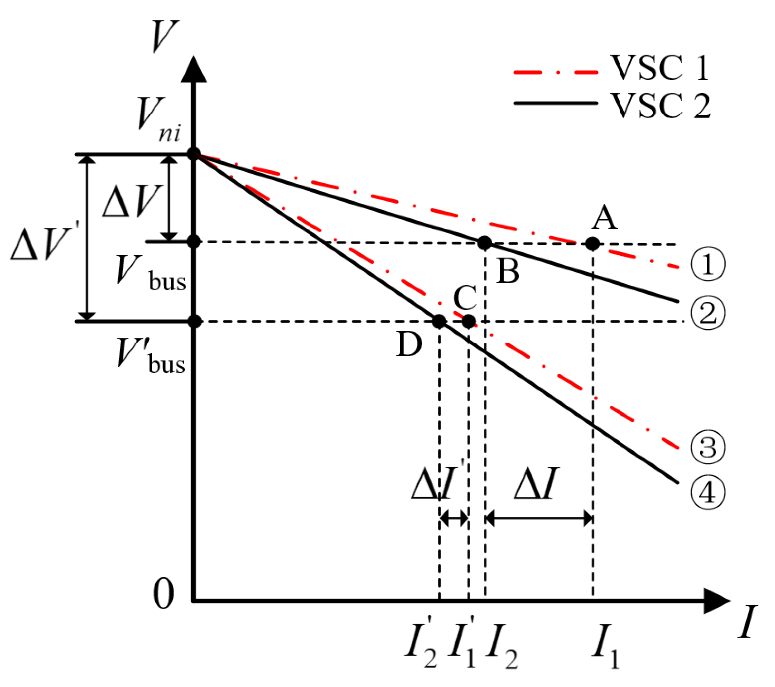
2.3. Analysis of the Improved Droop Control Characteristics

Since uncertainty and disturbance estimation terms are introduced into the droop control design of Section 2.2, combining Equations (15), (17) and (19), the error dynamics of the i-th source converter can be obtained as:
e ˙ i = K i e i σ i σ ^ i = K i e i L 1 1 G f i ( s ) σ i
Since σ i is bounded and the chosen filter strictly complies with the specifications, implying G f i ( 0 ) = 1 after Laplace transformation can obtain:
lim t e i = lim s 0 s E i ( s ) = lim s 0 s σ i ( s ) 1 G f i ( s ) s + K i = 0
From Equation (21), the steady-state tracking error of the load current of the VSC in the DC distribution network is e i = 0 , then corresponding to Figure 4 and Equation (5), there is:
I d c i = I i r e f = I l o a d n s i + V d c * V b u s n d i
As described in Section 2.2.1, the n d i and n s i of each converter are proportional. That is, there must exist a droop coefficient d satisfying: n d i = n s i d . Thus,
n s i I d c i = I l o a d + 1 d V d c * V b u s
All terms ( I l o a d , V d c * , V b u s , and d ) to the right of the medium sign of Equation (23) are the same for all the parallel source converters in the DC distribution network. It shows that the output current of each source converter is not affected by its output impedance and line impedance and can be reasonably shared according to its capacity. Compared to traditional droop control, this improved droop control can enhance the disturbance immunity and dynamic performance.

3. Improvement of VSC Current Inner Loop for Tracking Performance in the DC Distribution Network

In the DC distribution network, the quality of the voltage operation is not only related to the control strategy between the converter stations, but also to each converter’s operating performance. The VSC current inner loop PI control can theoretically achieve a zero steady-state error tracking effect. However, when there are uncertainties in the structural parameters and operational disturbances in the DC distribution network, these will affect the tracking effect of the current inner loop PI control and then affect the voltage operation quality of the DC system. Based on the UDE control method, a system-state model with disturbances and a desired reference model will be developed in this section to improve the tracking performance and immunity of the VSC current inner loop control in DC distribution networks. Furthermore, the control input variables are derived with the control objective that the system state model tracks the reference model, achieving an improved control of the VSC current inner loop.

3.1. The Disturbance Model of the VSC d-Axis Current

In this paper, a three-phase, two-level VSC is used. Considering the AC-DC system power balance, the mathematical model of the VSC in Figure 1 in the dq-axis coordinate system [26] is written as:
L s d i d d t = R s i d + ω L s i q + u s d u c d L s d i q d t = R s i q ω L s i d + u s q u c q ,
where L s is the AC side equivalent inductance and leakage inductance, R s is the AC side equivalent resistance, u s d , u s q , i d , and i q are the dq-axis components of the grid voltage and current, respectively, u c d and u c q are the dq-axis control signals of the VSC, respectively, and ω is the AC system angular frequency.
Due to the symmetry of the dq-axis of the VSC current inner loop, the VSC current inner loop control system will be reconstructed in the following with the d-axis as an example. Based on the UDE control theory, the state variable is chosen as x ( t ) = i d , the control input variable is taken as u ( t ) = u c d , and the disturbance variable, determined by Equation (24), is d 0 ( t ) = u s d L s 0 + ω i q . Thus, the disturbance model of the d-axis current can be established as follows:
i ˙ d = R s 0 + r o n 0 L s 0 i d 1 L s 0 u c d + ω i q + u s d L s 0 + σ d ( t ) ,
where the subscript “0” indicates the parameter’s nominal value and σ d ( t ) is the total uncertainties and disturbances of the d-axis, which can be expressed as:
σ d ( t ) = Δ L s L s 0 d i d ( t ) d t + Δ R s + Δ r o n L s 0 i d ( t ) + Δ L s ω L s 0 i q ( t ) + Δ L s L s 0 ( u s d ( t ) u c d ( t ) ) + f d ( t )
Here, Δ L s = L s L s 0 , Δ R s = R s R s 0 , and Δ r o n = r o n r o n 0 and f d ( t ) is the unknown disturbance in the d-axis, including unpredictable disturbances such as common DC bus voltage disturbances and data measurement errors in the DC distribution network.

3.2. The Desired Reference Model for the VSC d-Axis Current

In establishing the desired reference model of the VSC d-axis current, the reference state variable is chosen as x m ( t ) = i d m and the system reference command is taken as u m ( t ) = i d r e f , where i d r e f is the current reference value generated by the voltage outer loop.
The voltage outer loop generates the current reference for the VSC current inner loop control. In order to avoid the interference of the high-frequency component of the current reference to the current inner loop, the low-pass filter is designed as follows:
i d m = μ s + μ i d r e f ,
where μ is the filter bandwidth.
Rewriting Equation (27) in the form of state-space equations, the desired reference model of the d-axis current can be obtained as:
i ˙ d m = μ i d m + μ i d r e f

3.3. Implementation of the VSC d-Axis Current’s Trackability

To improve the trackability of the VSC current inner loop control in DC distribution networks, the idea of improving the current inner loop control is to generate a control input variable u ( t ) = u c d , so that the system model can asymptotically track the desired reference model. That is, the state variable i d converges to the reference state variable i d m .
The tracking error is defined as:
e ( t ) = i d m i d
The expected tracking error converges asymptotically to 0, which needs to satisfy:
e ˙ ( t ) = ( μ + K ) e ( t ) ,
where K is the error feedback gain, usually letting K 0 . Since μ + K > 0 , Equation (30) is asymptotically stable. Combining Equations (25) and (28)–(30), it is known that the control input variable u c d needs to satisfy:
u c d L s 0 = μ i d r e f + ( R s 0 + r o n 0 L s 0 μ ) i d + K e ( t ) ω i q u s d L s 0 σ d ( t )
Let all the uncertainties and disturbances of the d-axis current during the VSC operation control be σ d ( t ) . Then, a filter G f ( s ) is designed to estimate and eliminate the disturbances σ d ( t ) . That is, G f ( s ) can be made to pass all the frequency components corresponding to σ d ( t ) , and G f ( s ) = λ s + λ . Letting g f ( t ) be the impulse response of G f ( s ) , σ d ( t ) can be predicted as:
σ ^ d ( t ) = σ d ( t ) g f ( t )
Substituting Equation (32) into Equation (31) and letting K = 0 yields:
u c d = L s 0 μ i d r e f + ( μ R s 0 + r o n 0 L s 0 ) i d + ω i q + σ d ( t ) g f ( t )
After Laplace transform, the frequency-domain control model of the VSC d-axis current inner loop can be obtained by solving Equation (33) as:
u c d ( s ) = L s 0 ( μ i d m ( s ) μ i d r e f ( s ) ) ( μ + λ + μ λ s ) e s + ( R s 0 + r o n 0 L s 0 i d ( s ) + ω i q ( s ) + u s d ( s ) L s 0 )
Equation (34) consists of three terms: the first term is a feedforward differentiation to generate a desired reference for the system-state variables; the second term is a PI-like control to drive the system-state variables to track the reference model; and the third term is the model inverse form to compensate for and eliminate the known dynamic part of the model.
In summary, the structure of the voltage-power coordinated control system based on a UDE in the DC distribution network is shown in Figure 5. The system includes the improved droop control part, the VSC voltage outer loop PI control part, the improved VSC current inner loop control part, and the VSC electrical part of the DC distribution network.

4. Simulation Verification and Analysis

To verify the accuracy of the proposed control strategy, the simulation model of a typical three-source 780 V DC system, as shown in Figure 1, is built in PSCAD/EMTDC software. Table 1, Table 2 and Table 3 list the system parameters and controller parameters.

4.1. Parameter Tuning Simulation of the Improved Current Inner Loop Controller

According to the UDE control theory, the parameter tuning of the UDE controller has two degrees of freedom characteristics between its anti-disturbance and tracking performance [23]. In order to obtain the general tuning law and determine the optimal control parameter values, this part simulates and analyzes the effects of μ and λ on the VSC’s stability, trackability, and transient characteristics.
The total simulation time for simulation condition 1 is 1 s . All the controls of the DC system are active at 0.2 s. After the system resumes its normal operation, the single-phase grounding fault occurs in the AC grid at 0.5 s, and the fault is eliminated at 0.55 s. In the parameter tuning, the values of μ and λ are kept unchanged, respectively, and another value is gradually increased to obtain the simulation results, as shown in Figure 6 and Figure 7. Figure 6 shows the simulated waveforms of the VSC output voltage V dc and d-axis current i d after adjusting λ when μ = 800   rad / s . Figure 7 shows the simulated waveforms of V dc and i d after adjusting μ when λ = 800   rad / s . Since the tracking effect of the d-axis current and the q-axis current in the simulation is consistent, the d-axis current simulation waveform is adopted.
Comparing Figure 6(a1–a4) for μ = 800   rad / s , when the fault occurs in the AC system at 0.5 s, when λ = 800   rad / s and λ = 1500   rad / s , the V dc does not reach the steady-state setting value before the fault disappears at 0.55 s. After increasing λ to 3000 rad/s and 5000 rad/s, the V dc can reach the set value by 0.55 s, even if the AC system still has a fault. This indicates that, under the condition of μ = 800   rad / s , increasing λ is beneficial to enhancing the VSC regulation speed during the disturbance and to improving the transient performance.
When the system resumes steady-state operation after the fault disappears at 0.55 s, the V dc are stabilized at 781.29 V, 780.81 V, 780.13 V, and 780.13 V under λ = 800   rad / s , λ = 1500   rad / s , λ = 3000   rad / s , and λ = 5000   rad / s , respectively. The recovery times are 0.0335 s, 0.0330 s, 0.0275 s, and 0.0275 s, respectively, which indicates that increasing λ can make the VSC obtain a more satisfactory voltage tracking control effect faster for a certain μ . However, this tracking effect tends to be saturated when λ increases to 3000 rad/s. Then, comparing the d-axis current waveforms, the steady-state tracking errors of i d shown in Figure 6(b1–b4) are 0.01162 kA, 0.00898 kA, 0.00178 kA, and 0.00178 kA, and the recovery times for the steady-state values are 0.0639 s, 0.0635 s, 0.05775 s, and 0.05775 s, respectively. This shows that the tracking performance of the current is also enhanced, but gradually converges to an extreme value with an increase in λ . Therefore, increasing λ is beneficial to improving the control performance of the VSC current, but when λ increases to 3000 rad/s, the improvement in the control performance is not obvious.
Similarly, according to Figure 7(a1–a4), when λ = 800   rad / s , increasing μ can obtain a more satisfactory DC voltage control effect, but the voltage transient process tends to be consistent after increasing μ to 3000 Ω/s. Taking the d-axis current waveform as an example, after the disturbance of the AC system is eliminated at 0.55 s, the recovery times of i d , as shown in Figure 7(b1–b4), are 0.0639 s, 0.0536 s, 0.0478 s, and 0.0478 s, respectively, indicating that increasing the μ value is conducive to the recovery of the d-axis current and improving the transient performance. For the tracking performance, the steady-state tracking errors of i d are 0.01162 kA, 0.00749 kA, 0.00336 kA, and 0.00336 kA, respectively, and the V dc are stabilized at 781.29 V, 780.53 V, 780.38 V, and 780.38 V, respectively, indicating that the tracking performance is excellent and tends to be saturated with an increasing μ .
Comparing the simulation results of Figure 6 and Figure 7, it can be seen that, for the two control parameters μ and λ , keeping one constant and adjusting the other value can positively improve the control performance. In other words, when the system is disturbed, the VSC current loop exhibits a reliable tracking performance and swiftly adjusts the voltage to restore the stability. However, when it increases to 3000 rad/s, the control performance tends to stabilize and the improvement effect is not obvious, so the optimal control parameters are μ = 3000   rad / s ,   λ = 3000   rad / s .

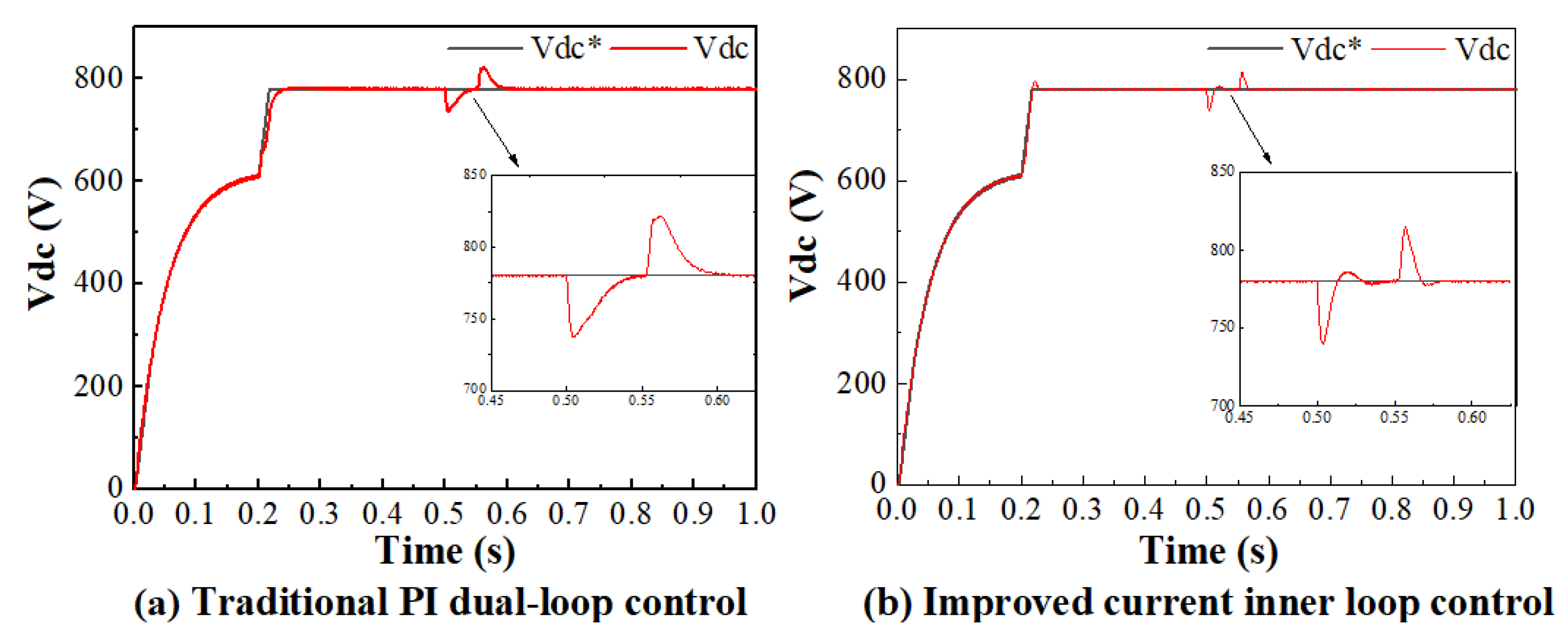
4.2. Simulation Verification of VSC Current Inner Loop Tracking Improvement in the DC Distribution Network

For the VSC current inner loop controller, the control effect is directly reflected in the trackability and immunity of the current inner loop output, i d and i q , which is beneficial to improving the robustness of the DC bus voltage control. In this section, the VSC in the three-source DC system shown in Figure 1 is taken as the research object to simulate and compare the control effect of the improved VSC current inner loop control strategy and traditional PI control strategy.
The PI controller outer loop parameters are shown in Table 3, and the improved VSC current inner loop controller parameters are μ = 3000   rad / s and λ = 3000   rad / s . The simulation results under simulation condition 1 are shown in Figure 8, as well as Figure 9. Figure 8a,b show the d-axis and q-axis currents of the VSC under the traditional PI dual-loop control, and Figure 8c,d show the d-axis and q-axis currents under the improved current inner loop control.
From Figure 8b,d, it can be seen that the trackability of the q-axis current components of both control methods in the steady-state case is within the ideal range, because the q-axis current reference value is set to 0 A in the VSC dual-loop control. At the moments of 0.5 s and 0.55 s, when the AC system fault occurs and disappears, the peak q-axis currents are 0.0148 kA and −0.013 kA for the traditional PI control and 0.013 kA and −0.002 kA for the improved current inner loop control, respectively. The fluctuation range of the actual q-axis current is significantly smaller than the former, indicating that the anti-interference ability of the improved current inner loop control is significantly better than that of the traditional PI control.
From Figure 8a,c, it can be seen that, for the d-axis current, both controllers have a good trackability in the steady-state case. At 0.2 s control access, the traditional PI control does not track as well as the improved current inner loop control. The moments of adjustment to the steady-state value for both are 0.31 s and 0.25 s, respectively, indicating that the proposed control strategy has a better transient response and tracking performance.
The VSC output voltage curves under the traditional PI dual-loop control and the improved current inner loop control are shown in Figure 9.
Figure 9 shows that the current inner loop has a small steady-state error under both control strategies. The voltage restoration stabilization times under the two control strategies are 0.050 s and 0.039 s at the moment of 0.5 s, when the single-phase ground fault occurs at the AC power end, and at the moment of 0.55 s, when the fault is removed, indicating that the improved inner loop current control has a faster regulation speed. After the fault, the voltage peaks corresponding to the two moments of 0.5 s and 0.55 s are 736.7 V and 821.6 V under the traditional PI control and 739.3 V and 814.5 V under the improved current inner loop control, indicating a better voltage robustness under the improved current inner loop control.
The comparison of the three waveforms from Figure 8 and Figure 9 illustrates that the effect of system disturbances on the VSC i d and i q is weakened after applying the improved current inner loop control, which is beneficial to improving the voltage transient performance of the DC distribution network.

4.3. Performance Verification of the Voltage-Power Coordinated Control Strategy for the Three-Source DC Distribution Network

The proposed coordinated controller is applied to the three-source DC distribution network in Figure 1 to verify the control effectiveness in both DC bus voltage regulation and load current sharing. The comparison control strategies are the traditional droop control and the VSC current inner loop PI control.
Under simulation condition 2, the total simulation time is 6 s. All the controls of the DC system are active at 0.2 s, and the DC side capacitance C e q of VSC2 varies from 7.8 mF to 15.6 mF at 1 s. VSC2 is withdrawn from the system operation due to the fault at 1.5 s, and a resistive load of 0.28 MW is connected to the DC bus at 3 s. The photovoltaic module is connected to the DC bus at 4 s. The simulation results under the two control strategies are shown in Figure 10a,b, which are the DC voltage V b u s and VSC current I d c under the traditional control. Figure 10c,d show the V b u s and the I d c under the coordinated control.
From Figure 10a,c, it can be seen that, when the DC system is started up with consecutive disturbances, such as parameter changes, the VSC2 withdrawal, load increase, and PV unit access, the voltages V b u s under the traditional control corresponding to the five periods are 760.1 V, 775.6 V, 740.6 V, 708.8 V, and 746.7 V, respectively, which show large variations compared to the rated voltage of 780 V. In contrast, the voltages V b u s for the five periods under the coordinated control are 780.07 V, 780.03 V, 780.06 V, 778.50 V, and 780.07 V, respectively, and all of them can recover to near 780 V in a shorter time.
Meanwhile, comparing Figure 10b,d, the regulation ability of the two control strategies for each VSC current sharing can be analyzed. In the simulation, the control objective of each VSC load current is to share the load current in equal proportion to its capacity. Taking the VSC2 out of operation at 1.5 s, for example, the load currents of the VSC1 and VSC3 with the same capacity are stabilized at 0.1246 kA and 0.1693 kA, respectively, in Figure 10b, without equalizing the currents until the next disturbance at 3 s. Under the coordinated control proposed in this paper, as shown in Figure 10d, the currents of the VSC1 and VSC3 are adjusted from 0.1813 kA and 0.2110 kA at 1.5 s to the same current value of 0.194 kA at 2.3 s when the VSC2 is withdrawn.
Obviously, the comparative analysis reveals that the improved droop control effectively distributes the load current to each power source based on its capacity when disturbances occur during operation. As a result, each power source is fully utilized. Additionally, the enhanced tracking and disturbance immunity of the VSC current inner loop enables the rapid restoration of the DC system voltage to its rated value after disturbances. This contributes significantly to improving the voltage quality and operational stability of the DC system.

5. Conclusions

The voltage stability control of the DC distribution network is not only related to the control strategy between the converter stations, but is also closely related to the VSC control strategy. In this paper, a voltage-power coordinated control strategy of the DC distribution network based on a UDE is proposed, with the control objective of improving its voltage stability while achieving reasonable load current sharing, which includes an improved droop control strategy and improved VSC current inner loop control strategy.
The main findings of this study can be summarized as follows:
(i) To achieve a reasonable sharing of load power among power sources and enhance the operational quality of a DC system’s voltage, an improved droop control strategy based on a UDE is proposed. Firstly, the capacity ratio of each source converter is introduced into the droop control. Subsequently, the traditional droop control commonly used in DC distribution networks is improved based on the UDE control theory. Through simulation verification, the proposed droop control method in this study demonstrates a superior load current sharing performance and DC system voltage stability compared to traditional droop control, even under disturbances such as power source variations and changes in the system parameters.
(ii) To enhance the tracking performance and anti-disturbance ability of the VSC current inner loop control, as well as to enhance the voltage stability of the DC system, the VSC current inner loop control is improved based on a UDE. The simulation results indicate that the proposed VSC current inner loop controller exhibits excellent tracking and immunity to disturbances during AC system faults, with minimal transient processes. These advancements contribute to strengthening the robustness and stability of the DC system’s voltage.
This paper focused on the stability of the DC bus voltage and reasonable power sharing of DC distribution networks. It primarily involved a theoretical analysis level, combined with engineering applications that still have limitations, such as a lack of consideration for the communication between the converter stations’ coordinated control, as well as the absence of considerations for operational variable collection and the implementation of hardware and software for the controllers. These aspects warrant further research and attention in future studies.

Author Contributions

Conceptualization, L.L. and H.T.; methodology, L.L. and H.T.; software, H.T.; validation, L.L.; writing—original draft preparation, H.T.; writing—review and editing, X.K. and Y.C.; supervision, L.L. and Z.Z.; modification, H.L. and Y.L. All authors have read and agreed to the published version of the manuscript.

Funding

This research received no external funding.

Data Availability Statement

No applicable.

Acknowledgments

The authors would like to express special thanks for the constructive comments from the editor and reviewers, leading to significant improvements to the manuscript.

Conflicts of Interest

The authors declare no conflict of interest.

References

  1. Ahmed, M.; Meegahapola, L.; Vahidnia, A.; Datta, M. Stability and Control Aspects of Microgrid Architectures-A Comprehensive Review. IEEE Access 2020, 8, 144730–144766. [Google Scholar] [CrossRef]
  2. Li, Y.; He, L.; Liu, F.; Li, C.B.; Cao, Y.J.; Shahidehpour, M. Flexible Voltage Control Strategy Considering Distributed Energy Storages for DC Distribution Network. IEEE Trans. Smart Grid. 2019, 10, 163–172. [Google Scholar] [CrossRef]
  3. Davari, M.; Mohamed, Y. Robust Droop and DC-Bus Voltage Control for Effective Stabilization and Power Sharing in VSC Multiterminal DC Grids. IEEE Trans. Power Electron. 2018, 33, 4373–4395. [Google Scholar] [CrossRef]
  4. Hu, J.; Shan, Y.; Cheng, K.W.; Islam, S. Overview of Power Converter Control in Microgrids—Challenges, Advances, and Future Trends. IEEE Trans. Power Electron. 2022, 37, 9907–9922. [Google Scholar] [CrossRef]
  5. Li, G.; Du, Z.; Shen, C.; Yuan, Z.; Wu, G. Coordinated Design of Droop Control in MTDC Grid Based on Model Predictive Control. IEEE Trans. Power Syst. 2018, 33, 2816–2828. [Google Scholar] [CrossRef]
  6. Pokharel, K.; Li, W.L.; Sapkota, S.; Zhang, Y.S.; Zhao, H.W.; Saleem, U. Autonomous transient power management strategy based on improved droop control for DC microgrid. Electr. Eng. 2022, 104, 4321–4334. [Google Scholar] [CrossRef]
  7. Saeidinia, Y.; Arabshahi, M.R.; Mousavi, S.Y.M.; Biglari, M. Autonomous control of DC microgrid based on a hybrid droop control scheme for total generation cost and transmission power loss reduction. Electr. Eng. 2023, 105, 267–283. [Google Scholar] [CrossRef]
  8. Che, Y.; Zhou, J.; Li, W.; Zhu, J.; Hong, C. Advanced Droop Control Scheme in Multi-terminal DC Transmission Systems. J. Electr. Eng. Technol. 2018, 13, 1060–1068. [Google Scholar]
  9. Mokhtar, M.; Marei, M.I.; El-Sattar, A.A. An Adaptive Droop Control Scheme for DC Microgrids Integrating Sliding Mode Voltage and Current Controlled Boost Converters. IEEE Trans. Smart Grid. 2019, 10, 1685–1693. [Google Scholar] [CrossRef]
  10. Da Silva, W.; Oliveira, T.R.; Donoso-Garcia, P.F. Hybrid Distributed and Decentralized Secondary Control Strategy to Attain Accurate Power Sharing and Improved Voltage Restoration in DC Microgrids. IEEE Trans. Power Electron. 2020, 35, 6458–6469. [Google Scholar] [CrossRef]
  11. Liu, S.; Miao, H.; Li, J.; Yang, L. Voltage control and power sharing in DC Microgrids based on voltage-shifting and droop slope-adjusting strategy. Electr. Power Syst. Res. 2023, 214, 108814. [Google Scholar] [CrossRef]
  12. Ding, X.Y.; Yao, R.Y.; Zhai, X.H.; Li, C.; Dong, H.N. An adaptive compensation droop control strategy for reactive power sharing in islanded microgrid. Electr. Eng. 2020, 102, 267–278. [Google Scholar] [CrossRef]
  13. Han, Y.; Ning, X.; Li, L.; Yang, P.; Blaabjerg, F. Droop coefficient correction control for power sharing and voltage restoration in hierarchical controlled DC microgrids. Int. J. Electr. Power Energy Syst. 2021, 133, 107277. [Google Scholar] [CrossRef]
  14. Feng, X.; Tao, Y.; Cui, X.; Shao, K.; Wang, Y. Sliding mode and predictive current control strategy of the three-phase Vienna rectifier. J. Power Electron. 2020, 20, 743–753. [Google Scholar] [CrossRef]
  15. Zhao, Z.H.; Han, Z.P.; Liu, X.D.; Yao, J.; Ji, B.J.; Wang, S.Z.; Zhao, J.F. Optimal Tuning of the Current Loop for Dual-Loop Controlled Grid-Forming Converters Based on Active Damping Optimization. IEEE Access 2021, 9, 35801–35813. [Google Scholar] [CrossRef]
  16. Wu, B.N.; Gao, Z.Q.; Zhou, X.S.; Ma, Y.J.; Wang, C.L. Research and Simulation of DC Microgrid Three-Phase AC-DC Converter Control Strategy Based on Double Loop. IEEE Access 2020, 8, 186448–186461. [Google Scholar] [CrossRef]
  17. Xin, Z.; Wang, X.F.; Loh, P.C.; Blaabjerg, F. Grid-Current-Feedback Control for LCL-Filtered Grid Converters with Enhanced Stability. IEEE Trans. Power Electron. 2017, 32, 3216–3228. [Google Scholar] [CrossRef]
  18. Xia, C.; Wang, Z.; Shi, T.; He, X. An Improved Control Strategy of Triple Line-Voltage Cascaded Voltage Source Converter Based on Proportional-Resonant Controller. IEEE Trans. Ind. Electron. 2013, 60, 2894–2908. [Google Scholar] [CrossRef]
  19. Aharon, I.; Shmilovitz, D.; Kuperman, A. Uncertainty and Disturbance Estimator-Based Controllers Design Under Finite Control Bandwidth Constraint. IEEE Trans. Ind. Electron. 2018, 65, 1439–1449. [Google Scholar] [CrossRef]
  20. Sakthivel, R.; Harshavarthini, S.; Tatar, N.E. Disturbance estimation based tracking control for periodic piecewise time-varying delay systems. IET Control Theory Appl. 2021, 15, 459–471. [Google Scholar] [CrossRef]
  21. Tian, Z.; Zhong, Q.C.; Ren, B.B.; Yuan, J.Q. Stabilisability analysis and design of UDE-based robust control. IET Control Theory Appl. 2019, 13, 1445–1453. [Google Scholar] [CrossRef]
  22. Zhong, Q.C.; Wang, Y.Q.; Ren, B.B. UDE-Based Robust Droop Control of Inverters in Parallel Operation. IEEE Trans. Ind. Electron. 2017, 64, 7552–7562. [Google Scholar] [CrossRef]
  23. Ren, J.J.; Ye, Y.Q.; Xu, G.F.; Zhao, Q.S.; Zhu, M.Z. Uncertainty-and-Disturbance-Estimator-Based Current Control Scheme for PMSM Drives with a Simple Parameter Tuning Algorithm. IEEE Trans. Power Electron. 2017, 32, 5712–5722. [Google Scholar] [CrossRef]
  24. Ye, Y.Q.; Xiong, Y.K. UDE-Based Current Control Strategy for LCCL-Type Grid-Tied Inverters. IEEE Trans. Ind. Electron. 2018, 65, 4061–4069. [Google Scholar] [CrossRef]
  25. Zhong, Q.C. Robust Droop Controller for Accurate Proportional Load Sharing Among Inverters Operated in Parallel. IEEE Trans. Ind. Electron. 2013, 60, 1281–1290. [Google Scholar] [CrossRef]
  26. Deng, W.; Pei, W.; Wu, Q.; Zhuang, Y. Analysis of Interactive Behavior and Stability of Low-Voltage Multiterminal DC System Under Droop Control Modes. IEEE Trans. Ind. Electron. 2022, 69, 6948–6959. [Google Scholar] [CrossRef]
Figure 1. Structure of the DC distribution network and its voltage-power control system.
Electronics 12 03137 g001
Figure 2. Steady-state equivalent circuit for double-terminal DC distribution system.
Electronics 12 03137 g002
Figure 3. Droop characteristic curves with different droop coefficients.
Electronics 12 03137 g003
Figure 4. The improved droop controller structure in the DC distribution network.
Electronics 12 03137 g004
Figure 5. The voltage-power coordinated control system in the DC distribution network (d-axis).
Electronics 12 03137 g005
Figure 6. The VSC control characteristics with μ = 800   rad / s when λ is adjusted: (a1a4) output voltage of VSC; (b1b4) d-axis current of VSC.
Electronics 12 03137 g006
Figure 7. The VSC control characteristics with λ = 800   rad / s when μ is adjusted: (a1a4) output voltage of VSC; (b1b4) d-axis current of VSC.
Electronics 12 03137 g007
Figure 8. Output current of d/q axis of VSC: (a,b) with traditional PI dual-loop control; (c,d) with improved current inner loop control.
Electronics 12 03137 g008
Figure 9. Output voltage of VSC: (a) with traditional PI dual-loop control; (b) with improved current inner loop control.
Electronics 12 03137 g009
Figure 10. The droop characteristic verification in the DC distribution network: (a,b) with traditional droop control; (c,d) with coordinated control.
Electronics 12 03137 g010
Table 1. System parameters.
System ParameterThe VSC1The VSC2The VSC3
Grid-side voltage amplitude V s / V 380380380
Grid-side voltage phase angle δ / degree 000
AC-side resistance R s / Ω 0.030.030.03
AC-side inductance L s / mH 0.250.250.25
DC-side capacitance C e q / μ F 780078007800
DC-side inductance L e q / mH 0.10.10.1
Converter losses P l o s s / kW 555
Grid-connected line resistance R l / Ω 0.30.20.2
Grid-connected line inductance L l / mH 0.060.020.02
Converter transmitted active power rating P / MW 5
Converter transmitted reactive power rating Q / MVar 0
Grid-side frequency f / Hz 50
Switching frequency f s 1 / Hz 8000
Table 2. Parameters of PV system.
PV ParameterPV Parameter Values
Temperature   T / ° C 20
Radiation   intensity   G ( W / m 2 ) 600
Maximum   transmitted   active   power   P p v max / MW 0.5
Filter   inductance   L p / mH 0.1
Filter   capacitance   C p / μ F 3000
Grid - connected   line   resistance   R l p v / Ω 0.2
Grid - connected   line   inductance   L l p v / mH 0.01
Switching   frequency   f s 2 / Hz 3600
Table 3. Parameters of the controller.
Controller LoopsController ParameterController Parameter Values
The VSC inner loop (d-axis) k pi ( Ω ) 0.5
k ii ( Ω / s ) 1/0.08
The VSC outer loop (d-axis) k pv ( Ω ) 3.5
k iv ( Ω / s ) 1/0.0035
The VSC inner loop (q-axis) k pi ( Ω ) 0.5
k ii ( Ω / s ) 1/0.08
The VSC outer loop (q-axis) k pq ( Ω ) 0.3
k iq ( Ω / s ) 1/0.02
Droop control coefficient R d i ( kV / kA ) 3
Boost transformer coefficient k p b o o s t ( Ω ) 1
k i b o o s t ( Ω / s ) 0.5
Disclaimer/Publisher’s Note: The statements, opinions and data contained in all publications are solely those of the individual author(s) and contributor(s) and not of MDPI and/or the editor(s). MDPI and/or the editor(s) disclaim responsibility for any injury to people or property resulting from any ideas, methods, instructions or products referred to in the content.

