Abstract
A diffractive imaging system consisting of two satellites is analyzed in view of dynamics. The mathematical model of rigid and flexion couples is studied to describe the relative motion of diffractive satellites and imaging satellites. Based on an integrated dynamics model with dual quaternion, a fixed-time non-singular terminal sliding mode controller is designed to meet the requirements of Earth observation. Finally, introducing the non-singular terminal sliding mode as the control group, a comparative simulation of relative motion and control is implemented to verify the controller and dynamics model.
1. Introduction
Mega constellations make the implementation of 6G mobile networks possible; furthermore, earth observation satellites are important for the construction of space-based Internet of Things. High resolution is an important development direction for the Earth observing system (EOS). To meet the requirements of the rocket launch envelope and realize the giant aperture optical imaging, the thin film diffraction imaging technique has been studied by many scholars as a new imaging technique. Diffractive films have the advantages of being lightweight, having changeable face shapes, having smaller face densities, being low cost, and being easy to fold and unfold compared to conventional optical imaging loads. Thin film diffraction imaging is one of the most promising and effective methods and technical implementations used to solve the problem of very large aperture and ultra-light load imaging systems in space [1,2].
In the area of diffraction imaging, research institutions have conducted a lot of exploration and experiments. In 1998, the Lawrence Livermore National Laboratory (LLNL) proposed the Eyeglass program, which used two satellites, an objective, and an eyepiece to form a telescope system [3,4]. Ground prototypes proved the feasibility of diffraction imaging technology. In 2010, the Defense Advanced Research Projects Agency (DARPA) of the US Department of Defense announced the MORIE (Membrane Optical Imager Real-time Exploration) satellite research program, which made significant improvements based on the Eyeglass program [5,6]. The Royal Observatory of the UK has proposed a 30 m diameter diffractive space telescope scheme similar to the Eyeglass project; it is named GISMO and is based on relevant research from LLNL [7,8]. The French Space Research Center has proposed the Fresnel Diffractive Array Imager (FDAI) with a 20 m Fresnel diffractive array as its primary mirror aperture, which is expected to be launched in 2025 to verify the feasibility of Fresnel diffractive array imaging [9,10]. In 2019, the Falcon Satellite 7 developed by the US Air Force Academy for imaging the sun was successfully launched into orbit. The rigid arm structure of the Falcon Satellite 7 supports the 0.2 m diameter “photon sieve” carried to maintain its correct position. Falcon 7, as a pathfinder for future low-mass, high-resolution surveillance application missions, has verified in orbit the effectiveness of deployable photon sieve telescopes and successfully demonstrated space-based deployable diffractive film telescope technology; this has provided a basis for the next expansion to larger-scale spacecrafts and larger aperture diffractive film applications [11,12]. Sliding mode control is widely used in the field of spacecraft attitude and orbit control due to its fast response and insensitivity to system uncertain parameters, such as distributed attitude control [13], event-driven sliding mode robust control [14], and fixed-time active disturbance rejection high-order sliding mode control [15].
Many scholars have studied the modeling and control of the attitude orbit integration of rigid spacecrafts and the dynamic modeling of the attitude vibration coupling of rigid–flexible coupled spacecrafts; however, there are fewer studies considering the attitude orbit integration modeling and control of rigid–flexible coupled systems. Daero Lee used the exponential coordinates in SE (3) to represent the relative configuration of spacecrafts relative to the virtual leader for spacecraft formation flying (SFF) and established a coupled dynamics model of relative translation and rotation for rigid spacecraft formation [16,17]. Jun Sun et al. derived dynamic equations for the cross-coupling of the translation, rotation, and vibration of flexible rigid systems using dual quaternions within the same mathematical framework for high-precision, ultra-close range formation missions of spacecrafts carrying large-scale antenna arrays [18]. Henry D considered the coupling effects of large-scale solar cell array flexible attachments, propellant sloshing, and spatial disturbances for autonomous rendezvous in orbit. Based on dual quaternions, a single equation has been established to describe the rotation and motion dynamics of spacecrafts and an attitude–orbit integrated fault-tolerant controller has been designed [19]. Zhang Xianliang et al. considered the complex coupling effects between structural module deformation and vibration during transportation, as well as the translational and rotational maneuvers of the assembly robot; they designed an attitude orbit-integrated PD controller based on the relative dynamics model of the rigid torsion system derived from dual quaternions for the problem of the large-scale antenna in-orbit assembly [20]. Sun L et al. aimed at addressing the problem of short-range maneuvers of on-orbit service spacecrafts; a dynamics model based on dual quaternion was established and they further designed a fixed-time-tracking adjustment and drive allocation scheme for redundant driven spacecrafts [21].
In this paper, we propose a double-satellite formation diffractive thin-film imaging system in the context of high-resolution Earth observation. Aiming at the characteristics of “rigid flexure” coupled large aperture diffractive film satellites, an attitude orbit integration dynamics model based on dual quaternion is established. Considering the bounded interference in the complex space environment, a fixed-time non-singular terminal sliding mode controller for attitude orbit integration is derived. In Section 2, a brief introduction is given regarding basic knowledge of dual quaternions and fixed time theory. In Section 3, the relative dynamics model of the rigid–flexible coupled system is proposed; in Section 4, a fixed-time non-singular terminal sliding mode controller is designed to realize the position–attitude integrated control of the rigid–flexible coupled system. Finally, the simulation results are presented in Section 5 and the conclusions are given in Section 6.
2. Preliminaries
Compared with other methods that can represent spiral motion in space, dual quaternions have a concise and compact form with high computational efficiency. Roonye’s research has shown that dual quaternions are the most effective and concise form of spatial line transformation [22,23].
A dual quaternion is a pair of even numbers with elements of quaternion, as follows:
where and are ordinary quaternions, is a pair of even numbers, and is a pair of even vectors. According to Bottega’s conclusion, the unit dual quaternion is defined as [24]:
The Euler theorem states that the motion of any rigid body can be achieved by rotating around an axis and moving parallel to that axis [25]. The six degrees of freedom (6-DOF) transformation consisting of the rotated quaternion and the translated can be expressed as:
The vector rotates around axis n by an angle to obtain the vector , it is also possible to fix the vector rotation coordinate system, and the projection of the vector after rotation is derived from the projection before rotation.
Compared to quaternions that can only describe rotational motion, dual quaternions can describe helical motion, avoiding decomposing motion into two processes: rotation and translation.
As shown in Figure 1, spiral motion can be described as rotating the angle around the n-axis and then translating d along the n-axis. The coordinate system rotates the angle around the n-axis and then shifts d to obtain the coordinate system .
where, is the helical axis, and is the dual angle. The projection point of the origin of the coordinate system on the spiral n-axis is p. For a more detailed derivation, please refer to reference [24].
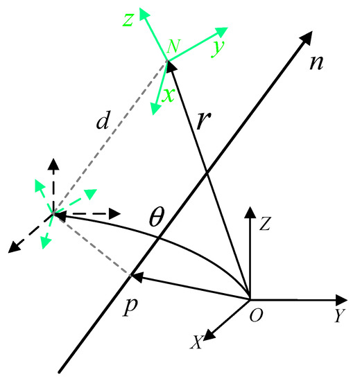
Figure 1.
Schematic diagram of coordinate transformation.
By analogy with Equation (5), the Plücker linear transformation can be expressed as . Where and are Plücker lines in the coordinate system and the coordinate system , respectively, specifically:
where , equivalent formulas can be derived:
Dual quaternions can be represented as:
The formula for a unit dual quaternion can be derived as follows:
3. Model Establishment
3.1. Mathematical Model of a Single Rigid–Flexion Coupled Spacecraft
As shown in Figure 2, the system consists of an imaging satellite and a diffraction thin film satellite, where the diffraction thin film satellite is mainly composed of a central rigid body and diffraction thin film. To derive the comprehensive dynamics model of the system, the following four basic assumptions are made in this article:
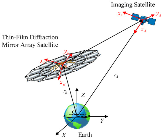
Figure 2.
Schematic diagram of dual star orbit position.
- (1)
- The main body of the spacecraft is rigid, and it can freely engage in unrestricted translational and rotational motion relative to inertial space.
- (2)
- The attachment is modeled as a flexible body that can be discretization by the finite element method, and its translational and rotational motions relative to the platform are limited.
- (3)
- Assuming that the elastic displacement of the satellite’s flexible attachment is very small, it follows the theory of linear elasticity.
- (4)
- The centroid of the entire system coincides with the geometric center, and the displacement of the system centroid caused by the vibration of flexible attachments is a negligibly small amount.
As shown in Figure 3, the thin film diffraction mirror array satellite (diffraction satellite) consists of a central rigid body , a flexible body , and a girder. The diffraction satellite can be simplified into rigid modules and flexible modules, which are marked with dashed and solid lines briefly indicating the state before and after deformation.
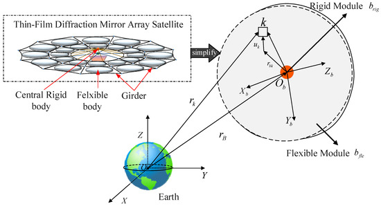
Figure 3.
Simplified flexible attachment model of the diffractive thin-film satellite.
The following reference coordinate system is introduced:
- (1)
- Earth-Centered Inertial (ECI) : Taking the center of the Earth as the origin, the x-axis points towards the vernal equinox along the intersection of the equatorial and ecliptic planes, the z-axis points towards the North Pole, and the y-axis is determined by the right-hand rule.
- (2)
- Satellite system: With the center of mass of the spacecraft as the origin, the x-axis, y-axis, and z-axis are the three inertia axes of the spacecraft.
- (3)
- Floating coordinate system : The floating coordinate system is the follow-up coordinate system for the flexible module to move relative to the attitude of the main spacecraft. When the origin of the coordinate system is attached to the material point of the flexible attachment space structure, the direction of the three-axis is determined by the attachment direction of the coordinate system; When the origin of the coordinate system is not attached to the material point of the flexible attachment structure, the position of the origin of the coordinate system and the direction of the three-axis is determined by the defined constraint conditions.
The motion of rigid–flexible coupling spacecraft B can be described as three translations and three rotations of its system relative to the inertial frame . Represent the angular velocity vector and velocity vector of this system relative to the inertial frame as and , respectively. As shown in Figure 2, is selected as the nominal point of flexible attachment. In addition, and are the position vector and elastic displacement vector of the point relative to the system, respectively. Wherein the elastic displacement vector is measured relative to this system.
The position vector of any point on the spatial structure of a flexible attachment in the earth-centered fixed coordinate system can be expressed as
where is the position vector of the origin in the floating coordinate system in the coordinate system, and is the position vector of the nominal point in the coordinate system . The elastic displacement vector is measured relative to the coordinate system and is the coordinate transformation matrix from the coordinate system to the coordinate system .
The component of the velocity vector of the nominal point relative to the centroid in the coordinate system can be expressed as:
where is the angular velocity vector of the nominal point relative to the center of mass in the coordinate system . Is always equal to , and represents the elastic velocity of the nominal point . Obviously, is always equal to , and represents the elastic velocity at the nominal point .
Brodsky and Shoham treat objects as a set of discrete mass elements, each of which corresponds to a unique velocity spinor [26,27]. The dual mass of the mass element is described as , The linear momentum of each mass element is the product of the dual mass and the velocity spin. Further, linear momentum and angular momentum can be combined to form dual momentum.
In addition, the dual operator and have complementary definitions:
The component of the dual velocity vector of the nominal point relative to the center of mass in the coordinate system can be expressed as a dual quaternion:
where , is the nominal point angular velocity vector and velocity vector described by the quaternion.
The dual momentum of the point relative to the center of mass in the coordinate system can be expressed as:
is the Hermitian matrix of points, where and are four-dimensional vectors related to and , respectively. is the dual mass of the point , and represents the dual momentum of the point .
Substituting Equation (13) into Equation (14), the dual momentum of the point can be expressed as:
Based on the finite element principle, the dual momentum components of the flexible attachment relative to the centroid along the system were obtained, as follows:
Substitute Equations (11) and (14) into Equation (13) to obtain the dual momentum of the flexible attachment :
where, is an extended four-dimensional vector of . is the cross-product extension matrix of and .
Because the elastic displacement modulus is much smaller than the attachment size, the elastic displacement can be ignored in the above calculation. Subsequently, Equation (17) can be transformed into
Bringing Equation (19) into Equation (18) yields
where
is the inertia matrix of the flexible attachment relative to the coordinate system. The component of the dual momentum of the flexible attachment in the coordinate system relative to the geocentric fixed inertial system is
where is the extension vector of the velocity vector component relative to the geocentric fixed coordinate system of the flexible spacecraft in its system.
The dual quaternion form expression for the displacement response of each node obtained by combining the flexible attachment modal superposition method is
where is the modal coordinate matrix, is the modal order, and is the eigenvector matrix of the point based on dual quaternion representation. Using is a convenient method to represent the dual displacement response of attachments; relates to the displacement response and has no physical meaning.
Define the stiffness torsion translational coupling matrix and the rotational coupling matrix as follows [20]:
Substitute Equations (23) and (24) into Equation (22) to obtain the dual momentum of the flexible attachment in the mixed coordinate system .
Convert to matrix form
where, and 0 are the identity matrix and zero matrix, respectively.
represents the dual inertia of the flexible attachment, represents the dual velocity vector of the system relative to the inertial frame, and represent the coupling matrix and modal coordinate matrix in the dual quaternion form. Equation (26) can be simplified as
3.2. An Integrated Relative Motion Model for Attitude Orbit of a Rigid–Flexion Coupled Spacecraft
3.2.1. Relative Kinematics Model
The relative motion between Spacecraft B and Spacecraft A can be regarded as the spiral motion of Spacecraft B relative to Spacecraft A, that is, the spiral motion from to , that is, the relative kinematics equation can be expressed as
where, and , and represents the relative attitude quaternion between spacecraft B and spacecraft A. , are the extended matrices of ,, and is the relative dual velocity spinor of the two spacecraft in the coordinate system.
Extended matrix with as , and are the angular velocity and centroid relative position vectors of spacecraft B relative to spacecraft A in the coordinate system, respectively. and , respectively, represent the dual velocity spinors of two spacecraft in their respective body coordinate systems, and can be expressed as
where , . and are the extended matrices of and , respectively, and is the conjugate of .
3.2.2. Relative Dynamics Model
The expression for the relative dual velocity spinor of two spacecraft in the coordinate system has been derived in the previous text. Further derivation of Equation (30) yields
Substituting the dynamics equation of a single spacecraft’s rigid torsion coupling system under dual quaternion description can obtain:
Equation (32) is the relative dynamics equation established based on dual quaternions. is the dual inertia matrix of spacecraft B which . is the dual forces acting on spacecraft B.
We expand the coupling terms and in Equation (32) into matrix form as follows:
Equation (33) consists of two parts, one of which represents the real part of the rotational relative dynamics coupling interaction, including the rotational coupling term , the translational coupling term , and the vibration coupling term . It illustrates the influence of the relative orbital translational and rigid–flexible coupling spacecraft vibration on the relative attitude operation of two spacecraft; the other part is the dual part that represents the coupling interaction between relative orbital motion, where , , and these terms describe the coupling interaction between vibration and rotation acting on the orbital motion. The dual part in Equation (34) has a term, indicating the impact of the relative attitude motion of two spacecraft on the orbital motion. In summary, these coupling terms describe the coupling effects between the relative posture and structural vibration of spacecraft.
In addition, the vibration equation of the flexible attachment in the coordinate system can be written as
3.3. A Dynamics Model for Relative Error Motion of Rigid–Flexion Coupled Spacecraft
Based on Equations (28) and (32), the relative error kinematics equation and relative error dynamics equation of rigid–flexible coupling spacecraft can be expressed as
where the relative error of dual quaternions can be expressed as , where and are error quaternions and error position vectors, respectively. is the dual force acting on the center of mass of the spacecraft, while is composed of gravitational force , control force , and interference force .
consists of gravity gradient torque , control torque , and interference torque . The velocity spin error can be expressed as , where is the expected velocity spin.
4. Fixed Time Non-Singular Terminal Sliding Mode Design
The convergence time of the traditional terminal sliding mode controller depends on the initial state. When the initial value is large, the time is long, which is unacceptable in practical engineering applications. This article is based on the fixed time theory and introduces a piecewise switching function to propose a globally fixed time convergent non-singular terminal sliding surface. Thus, the transition from finite time convergence to fixed time convergence is achieved, which improves the control response speed and accuracy [28,29].
Theorem 1.
Nonlinear system ,
where , , , , . The system converges to 0 within a fixed time, and the upper bound of its convergence time is
Proof of Theorem 1.
Select the Lyapunov function and differential the function to obtain
when , it can be equivalent to , where . When , it can be equivalent to , where .
In both cases, Equation (39) can be derived as , , Equation holds. Solve the time upper bound when the system converges to .
when , it can be equivalent to , where .
Equation (39) can be derived as , , and equation holds. The time upper bound for the system to converge to the origin can be solved as
According to References [30,31], the nonlinear system is a fixed-time stable system, and the origin is the equilibrium point of the system. The upper bound of the convergence time is
Theorem 2.
Nonlinear system, where , , , , , . The system converges to 0 within a fixed time, and the upper bound of its convergence time is
Proof of Theorem 2.
Select the Lyapunov function and differential the function to obtain
when , it can be equivalent to , where , . When , it can be equivalent to , where .
In the above two cases, Equation (44) can be derived as
Integrating both sides of Equation (46) simultaneously yields
According to [21,32], in the case of , the following equation holds
when , it can be equivalent to , where . Equation (44) can be derived as
Substituting into Equation (50) yields
The nonlinear system is a fixed-time stable system, and the origin is the equilibrium point of the system. The upper bound of the convergence time of the system is represented as follows:
For the integrated relative error model of the attitude orbit of a rigid–flexible coupling spacecraft described in Equations (36) and (37), this paper designs a fixed-time non-singular terminal sliding surface as follows:
where
Equation (52) , , , , and that is a constant with very small values.
Differentiate Equation (54) and further obtain from reference [33]:
The fixed-time nonsingular terminal sliding mode controller is as follows:
where , , , and are both positive definite diagonal matrices. Equation (54) is a continuous piecewise function. When converges to the region, the sliding surface shown in Equation (53) switches to a linear sliding surface form to avoid singular problems.
The proof will be divided into two steps:
Step 1
Prove that the system state converges to within a fixed time.
- Select Lyapunov function
Equation (57) is derived as:
Assuming that the interference received by the spacecraft is bounded, the of Equation (56) is substituted into Equation (58) for calculation.
According to Theorem 2, during the approaching stage of the sliding mode surface, the system state can reach within a fixed time.
Step 2
Prove that in the case of , the system state variables and converge to 0 in finite time.
When ,
when the Lyapunov function is selected as
Derive to obtain Equation (63):
According to Theorem 1, and converge within a fixed time after reaching the sliding surface.
when the equation holds and exponentially converges.
Proof completed.
5. Simulation and Results
To verify the feasibility and effectiveness of the control algorithm proposed in the previous section, mathematical simulations were conducted based on mathematical simulation software. The target orbit parameters of the spacecraft and the initial state error parameters of the tracking spacecraft relative to the target spacecraft are detailed in Table 1 and Table 2.

Table 1.
Six elements of spacecraft target orbit.

Table 2.
Initial state error parameters of spacecraft.
Set the target spacecraft to be oriented toward the ground with an angular velocity of .
Assuming that the rigid platform mass of the rigid–flexible coupling spacecraft is 80 kg, the mass of the flexible attachment is 20 kg, and the rotational inertia of the rigid platform and the flexible attachment are
For the convenience of calculation, the flexible mode of a rigid–flexible coupled spacecraft is simplified and equivalent to the flexible cantilever mode. Its initial mode is , and the specific parameter information is shown in Table 3.

Table 3.
Parameters of rigid–flexion coupled spacecraft.
Assuming that the spacecraft is subjected to the following environmental dual interference forces
Considering the actual control execution mechanism, in the simulation process of the following three sets of controller models, the control force and torque are limited to the range of and , respectively.
The fixed-time nonsingular terminal sliding mode controller is selected as follows:
To better compare the effect of fixed time convergence speed, the nonsingular terminal sliding mode controller is introduced as the control group. Its sliding mode surface and approach law (switching control term) are as follows:
where , . is a dual constant and . The parameters of the nonsingular sliding mode controller are selected as follows:
In order to present the simulation results more clearly and intuitively, this article calculates the relative dual quaternion into the form of relative attitude quaternion and relative position and also converts the attitude quaternion into Euler angle form, which is more conducive to visually observing and comparing the changes in attitude angle errors. The simulation results are shown in Figure 4, Figure 5, Figure 6, Figure 7, Figure 8, Figure 9, Figure 10, Figure 11, Figure 12 and Figure 13. The left side of the image is the fixed-time nonsingular sliding mode controller designed in this paper, and the right side of the image is the nonsingular terminal sliding mode control group.
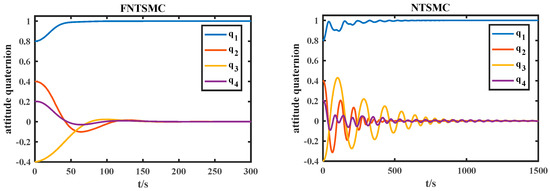
Figure 4.
Quaternion error curve of relative attitude.
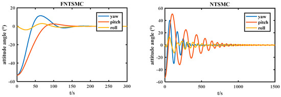
Figure 5.
Attitude angle error.
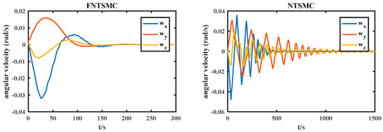
Figure 6.
Relative angular velocity error.
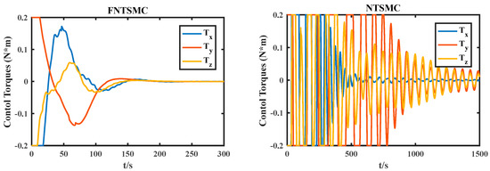
Figure 7.
Control torques.
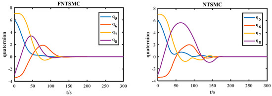
Figure 8.
Dual quaternion dual part.
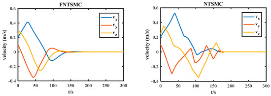
Figure 9.
Relative velocity error.
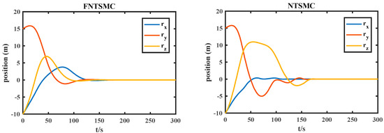
Figure 10.
Relative position error.
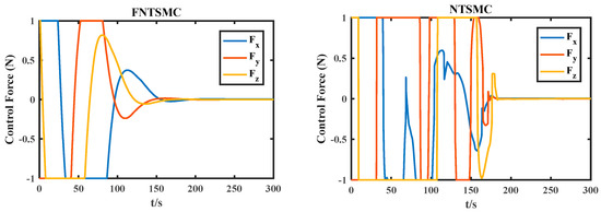
Figure 11.
Control force.
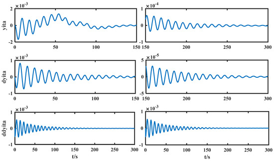
Figure 12.
Modal parameters of flexible attachments for FNTSMC.
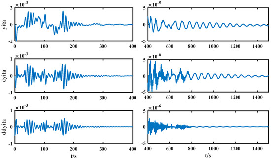
Figure 13.
Modal parameters of flexible attachments for NTSMC.
From Figure 4, Figure 5 and Figure 6, it can be seen that the relative attitude quaternion error, relative Euler angle error, and relative angular velocity error decrease over time. The fixed time nonsingular terminal sliding mode attitude quaternion and attitude angle converge to zero within 200 s, and the steady-state error accuracy can reach 10−4 within 300 s. The relative angular velocity error converges within 200 s. The attitude quaternion, attitude angle, and relative angular velocity errors of nonsingular terminal sliding mode converge within 1500 s due to the influence of the initial state of the system. The actual control torque output under conditions is shown in Figure 7.
Figure 8, Figure 9 and Figure 10 show the variation of the relative orbital motion parameters of the rigid–flexion coupling system, as shown in Figure 8. The dual part variation curve of the dual quaternion of the fixed time non-singular terminal sliding mode, that is, the orbital motion and attitude orbit coupling part converge to 0 within 150 s; the dual part of the nonsingular terminal sliding mode dual quaternion converges to 0 within 180 s.
As shown in Figure 9 and Figure 10, the relative position and relative velocity errors of the fixed time nonsingular terminal sliding mode converge to zero within 150 s, and the steady-state error can reach 10−3 after 300 s. The relative position and relative velocity errors of the nonsingular terminal sliding mode converge to zero within 180 s. Figure 11 shows the actual control force output under conditions.
Figure 12 and Figure 13, respectively, show the modal vibration curves of the fixed time nonsingular terminal sliding mode and the flexible attachment of the nonsingular terminal sliding mode controller in relative attitude orbit motion. The fixed time nonsingular terminal sliding mode flexible mode converges to the steady state within 150 s; the mode of the flexible attachment of the nonsingular terminal sliding mode controller tends to be stable within 400 s.
Through simulation and comparison, it can be concluded that under the same initial state and controller parameters of the same magnitude, the convergence time of nonsingular terminal sliding mode is relatively long, which is unacceptable in practical engineering applications. Fixed time control has stronger robustness, faster convergence speed, and higher convergence accuracy. The most important thing is that its convergence time is independent of the initial conditions and only depends on the control parameters. Therefore, it is more suitable for practical task applications, even if the task environment is different, there is no need to adjust the parameters accordingly. The simulation results show that the designed controller can improve the convergence speed, achieve a transition from finite time convergence to fixed time convergence, have good robustness, and improve the control performance of the system.
6. Conclusions
To better describe the dual star thin film diffraction imaging system, an integrated dynamics model and relative error motion and dynamics equations for the relative motion, attitude, and orbit of a rigid–flexible coupling spacecraft were established based on dual quaternions. Considering external interference, a fixed time convergent nonsingular terminal sliding mode surface is constructed by switching the power terminal of the system state variable to address the problem of integrated attitude and orbit control of rigid–flexible coupled spacecraft based on dual quaternion. Theoretical analysis and verification show that the controller proposed in this chapter can achieve state error convergence to zero, achieving a transition from finite time related to the initial state of the system to fixed time independent of the initial state of the system. Numerical simulation verifies the effectiveness of the proposed controller and introduces a nonsingular terminal sliding mode controller to compare and analyze the application advantages of the fixed-time nonsingular terminal sliding mode controller designed in this paper through numerical simulation.
Author Contributions
Y.Z.; validation, J.P.; formal analysis, J.P. and X.S.; resources, X.S.; writing—original draft, S.M.; writing—review and editing, Y.Z. and C.M.; supervision, B.L. and M.S. All authors have read and agreed to the published version of the manuscript.
Funding
This research was funded by Fundamental Research Funds for the Central Universities, grant number 3072022JC0202.
Data Availability Statement
The data presented in this study are available on request from the corresponding author.
Conflicts of Interest
The authors declare no conflict of interest.
References
- Ma, S.; Song, X.; Li, J.; Sun, Y.; Wang, Y. Adaptive tracking control for diffractive film based on nonlinear sliding mode. Trans. Nanjing Univ. Aeronaut. Astronaut. 2022, 39, 696–706. [Google Scholar]
- Enrique, J.F.; Pablo, A. Membrane deformable mirror for adaptive optics: Performance limits in visual optics. Opt. Express 2003, 11, 1056–1069. [Google Scholar]
- Hyde, R.A. Eyeglass-1 Very large aperture diffractive telescopes. Appl. Opt. 1999, 38, 4198–4212. [Google Scholar] [CrossRef]
- Daniel, C.; David, J. Technology for the next generation space telescope. In UV, Optical, and IR Space Telescopes and Instruments, Proceedings of the Astronomical Telescopes and Instrumentation, Munich, Germany, 27 March–1 April 2000; SPIE: Bellingham, DC, USA, 2000; Volume 4013, pp. 784–794. [Google Scholar]
- Qu, W.D.; Gu, H.R.; Tan, Q.F. Design of refractive/diffractive hybrid optical elements for beam shaping with large diffraction pattern. Chin. Opt. Lett. 2016, 14, 031404. [Google Scholar]
- Tandy, W.; Atcheson, P.; Domber, J.; Seltzer, A. MOIRE gossamer space telescope—Structural challenges and solutions. In Proceedings of the 53rd AIAA/ASME/ASCE/AHS/ASC Structures, Structural Dynamics and Materials Conference <BR> 20th AI, Honolulu, HI, USA, 23–26 April 2012. [Google Scholar]
- Hawarden, T.G.; Johnstone, C.; Johnstone, G. GISMO, an ELT in space: A giant (30-m) far-infrared and sub-millimeter space observatory. In Second Backaskog Workshop on Extremely Large Telescopes, Proceedings of the 2nd Backaslog Workshop on Extremely Large Telescopes, Backaskog, Sweden, 9–11 September 2003; SPIE: Bellingham, DC, USA, 2004. [Google Scholar]
- Staguhn, J.; Allen, C.; Benford, D.; Sharp, E.; Ames, T.; Arendt, R.; Chuss, D.; Dwek, E.; Kovacs, A.; Maher, S.; et al. GISMO, a 2mm bolometer camera optimized for the study of high redshift galaxies. J. Low Temp. Phys. 2008, 151, 709–714. [Google Scholar] [CrossRef]
- Berdeu, L. New progress on the Fresnel imager for UV space astronomy. Astrophys. Space Sci. 2014, 354, 147–153. [Google Scholar]
- Raksasataya, T.; de Castro, A.-I.G.; Koechlin, L.; Rivet, J.P. A space Fresnel imager for ultra-violet astrophysics: Example on accretion disks. Exp. Astron. 2011, 30, 183–194. [Google Scholar] [CrossRef]
- Machi, V. Air Force’s June R&D Launch to Test SpaceX’s Falcon Heavy Reusability in ‘Most Challenging’ Mission Yet. Defense Daily, 10 June 2019. Available online: https://www.defensedaily.com/air-forces-june-rd-launch-test-space-xs-falcon-heavy-reusability-challenging-mission-yet/space/ (accessed on 17 June 2023).
- Garrett-Glaser, B. SpaceX’s historic falcon heavy arabsat-6a launch is a success. Defense Daily, 12 April 2019. Available online: https://www.defensedaily.com/spacexs-historic-falcon-heavy-arabsat-6a-launch-success/uncategorized/ (accessed on 17 June 2023).
- Feng, Z.Y.; Wang, J.W.; Wan, N.; Li, H.Y. Distributed Adaptive NN-Based Attitude Synchronous Tracking Control with Input Saturation. Electronics 2023, 11, 4093. [Google Scholar] [CrossRef]
- Amrr, S.M.; Alturki, A.; Kumar, A.; Nabi, M. Prescribed Performance-Based Event-Driven Fault-Tolerant Robust Attitude Control of Spacecraft under Restricted Communication. Electronics 2021, 10, 1709. [Google Scholar] [CrossRef]
- Song, C.; Wei, C.; Yang, F.; Cui, N. High-Order Sliding Mode-Based Fixed-Time Active Disturbance Rejection Control for Quadrotor Attitude System. Electronics 2018, 7, 357. [Google Scholar] [CrossRef]
- Lee, D. Spacecraft coupled tracking maneuver using sliding mode control with input saturation. J. Aerosp. Eng. 2015, 28, 04014136.1–04014136.11. [Google Scholar] [CrossRef]
- Lee, D.; Sanyal, A.K.; Butcher, E.A. Asymptotic tracking control for spacecraft formation flying with decentralized collision avoidance. J. Guid. Control. Dyn. 2015, 38, 587–600. [Google Scholar] [CrossRef]
- Sun, J.; Zhang, X.; Wu, X.; Song, T. Dual-quaternion-based translation-rotation-vibration integrated dynamics modeling for flexible spacecraft. J. Aerosp. Eng. 2019, 32, 04018135.1–04018135.11. [Google Scholar] [CrossRef]
- Henry, D.; Zenteno-Torres, J.; Cieslak, J.; De Loza, A.F.; Dávila, J. A 6-DOF sliding mode fault tolerant control solution for in-orbit autonomous rendezvous. Aerosp. Sci. Technol. 2021, 118, 107050. [Google Scholar] [CrossRef]
- Zhang, X.; Zhu, W.; Wu, X.; Song, T.; Xie, Y.; Zhao, H. Dynamics and control for in-space assembly robots with large translational and rotational maneuvers. Acta Astronaut. 2020, 174, 166–179. [Google Scholar] [CrossRef]
- Sun, L.; Huang, Y.; Fei, H.; Xiao, B.; Yeatman, E.M.; Montazeri, A.; Wang, Z. Fixed-time regulation of spacecraft orbit and attitude coordination with optimal actuation allocation using dual quaternion. Front. Robot. AI 2023, 10, 1138115. [Google Scholar] [CrossRef] [PubMed]
- Martinez-Teran, G.; Urena-Ponce, O.; Soria-Garcia, G.; Ortega-Cisneros, S.; Bayro-Corrochano, E. Fast Study Quadric Interpolation in the Conformal Geometric Algebra Framework. Electronics 2022, 11, 1527. [Google Scholar] [CrossRef]
- Rooney, J. William Kingdon Clifford (1845–1879). In Distinguished Figures in Mechanism and Machine Science; Springer: Berlin/Heidelberg, Germany, 2007. [Google Scholar]
- Kenwright, B. A beginner guide to dual-quaternions: What they are, how they work, and how to use them for 3d character hierarchies. In Proceedings of the 20th International Conference in Central Europe on Computer Graphics, Visualization and Computer Vision, Plzen, Czech Republic, 26–28 June 2012. [Google Scholar]
- Selig, J.M. Geometric Fundamentals of Robotics; Springer: Berlin/Heidelberg, Germany, 2005. [Google Scholar]
- Brodsky, V.; Shoham, M. Dual numbers representation of rigid body dynamics. Mech. Mach. Theory 1999, 34, 693–718. [Google Scholar] [CrossRef]
- Brodsky, V.; Shoham, M. Derivation of dual forces in robot manipulators. Mech. Mach. Theory 1998, 33, 1241–1248. [Google Scholar] [CrossRef]
- Cui, L.; Jin, N.; Chang, S.; Zuo, Z.; Zhao, Z. Fixed-time ESO based fixed-time integral terminal sliding mode controller design for a missile. ISA Trans. 2022, 125, 237–251. [Google Scholar] [CrossRef]
- Jin, N.; Cui, L.; Chang, S.; Zong, Y. Fixed-time ESO-based fixed-time controller design for a Missile. In Advances in Guidance, Navigation and Control, Proceedings of the 2020 International Conference on Guidance, Navigation and Control, ICGNC 2020, Tianjin, China, 23–25 October 2020; Springer: Berlin/Heidelberg, Germany, 2021. [Google Scholar]
- Polyakov, A. Nonlinear feedback design for fixed-time stabilization of linear control systems. IEEE Trans. Autom. Control. 2012, 57, 2106–2110. [Google Scholar] [CrossRef]
- Zhang, L.; Xia, Y.; Shen, G.; Cui, B. Fixed-time attitude tracking control for spacecraft based on a fixed-time extended state observer. Sci. China Inf. Sci. 2021, 64, 212201. [Google Scholar] [CrossRef]
- Chen, C.; Li, L.; Peng, H.; Yang, Y.; Mi, L.; Wang, L. A new fixed-time stability theorem and its application to the synchronization control of memristive neural networks. Neurocomputing 2019, 349, 290–300. [Google Scholar] [CrossRef]
- Park, Y. Robust and optimal attitude stabilization of spacecraft with external disturbances. Aerosp. Sci. Technol. 2005, 9, 253–259. [Google Scholar] [CrossRef]
Disclaimer/Publisher’s Note: The statements, opinions and data contained in all publications are solely those of the individual author(s) and contributor(s) and not of MDPI and/or the editor(s). MDPI and/or the editor(s) disclaim responsibility for any injury to people or property resulting from any ideas, methods, instructions or products referred to in the content. |
© 2023 by the authors. Licensee MDPI, Basel, Switzerland. This article is an open access article distributed under the terms and conditions of the Creative Commons Attribution (CC BY) license (https://creativecommons.org/licenses/by/4.0/).