Abstract
The occurrence of high-amplitude magnetizing inrush current during the energization of a transformer without load poses significant challenges to the stable operation of both the transformer and the power grid, potentially leading to malfunctions in relay protection devices. This paper analyzes the underlying mechanisms of transformer inrush current and presents a novel approach utilizing a soft-start-based method for effectively suppressing inrush currents. The proposed method employs an inrush current suppressor comprising anti-parallel thyristors and filters to mitigate the adverse effects caused by the inrush current. A comparative study is conducted to evaluate the filtering efficacy of three types of filters incorporated in the inrush current suppressor: an LCLC damping filter, a high-order single trap filter and a high-order double trap filter. Through careful analysis and optimization, the high-order double trap filter with parallel RC damping damper is selected as the optimal configuration. To ensure effective suppression, it is necessary to incorporate a filter at the termination point of the anti-parallel thyristor. Additionally, a closed-loop control strategy is implemented to ensure a smooth start and actively suppress the magnetizing inrush current. To validate the effectiveness of the proposed method, comprehensive simulations are performed using Matlab/Simulink. The results demonstrate the successful suppression of inrush current and the maintenance of stable operation for the transformer. This inrush suppression method does not require considering the influence of residual magnetism and the grounding mode of the transformer’s neutral point. It is also suitable for various transformer structures and wiring methods, which makes it highly applicable.
1. Introduction
When a power transformer is switched on without a load or reconnected to the grid after a fault recovery, there is a risk of inrush current passing through the transformer’s differential protection. Due to the saturation of the magnetic flux within the transformer core and the nonlinear characteristics of the core material, the inrush current can exhibit a relatively large amplitude. This may ultimately lead to the failure of the transformer’s differential protection. In addition, misoperation can cause deformation of the transformer winding, ultimately reducing the lifespan of the transformer [1,2,3]. Moreover, the inrush current comprises multiple harmonic and DC components, thereby diminishing power quality within the system. Higher-order harmonics present in the inrush current can significantly damage susceptible power electronic devices connected to the system. Consequently, scholars have placed considerable emphasis on mitigating inrush current [4,5,6].
Exciting inrush current is the term used to describe the current that occurs when the magnetic flux within the core of a transformer reaches saturation levels. The magnitude of the inrush current is influenced by several factors, including the equivalent impedance of the transformer, the initial phase angle of the closing circuit, residual flux, the winding connection mode, and the structure and material of the core [7]. For three-phase transformers, consideration should also be given to the connection method of the three-phase winding, as well as the materials and structure of the three-phase core. To mitigate the impact of inrush current on the power network and effectively reduce transformer magnetizing inrush current, three main methods are commonly employed: (1) the series resistance method, (2) controlled closing strategy, and (3) switching inrush current suppression circuit. The utilization of the series resistance method aims to diminish the magnitude of magnetic flux that flows through the core by modifying the resistance value of the primary side [8]. This technique involves incorporating series resistors either at the primary side or at the neutral point of the transformer. Nevertheless, the efficacy of solely utilizing the series resistance method for suppressing inrush current is inadequate. Consequently, it is commonly employed in conjunction with other methods, and the selection of the optimal series resistance value remains a challenging task.
The controlled closing strategy involves the selection of the initial phase angle of the voltage and the reduction in the magnetic flux flowing through the iron core by weakening the transient magnetic flux [9]. The traditional phase-selection closing technology encompasses three main approaches: fast closing technology, delayed closing technology, and simultaneous closing technology. It is important to note that the simultaneous closing technology is exclusively applicable to the specific three-phase residual flux mode of the transformer. In this mode, one of the phases exhibits zero residual flux, whereas the other two phases possess the residual flux of equal magnitude but with opposite directions and at a higher intensity. Both the delayed closing technology and the fast closing technology employ a closing sequence in which one phase is closed initially, followed by the simultaneous closure of the remaining two phases. However, these technologies are only appropriate for three-phase transformers with neutral grounding. In the case of a three-phase transformer without a grounded neutral point, closing only one phase results in the power supply and transformer windings failing to form a complete circuit. Consequently, when closing an ungrounded neutral point transformer for the first time, at least two phases must be closed. In reference [10], a strategy was proposed for closing two phases initially and then closing the remaining one phase, taking into account the impact of residual flux on the neutral point ungrounded transformer. This reference also provided a calculation method for determining the optimal closing time. However, the dynamic magnetic flux during the closing process was not described. According to reference [11], determining the closing time and sequence of transformers can be achieved by controlling the opening time and sequence of three-phase circuit breakers, which is contingent on the controllable and high-precision opening of the circuit breakers. However, the opening and closing times should not be too far apart, and applying this method in engineering is challenging. The closing time chosen through the controlled closing strategy is intricately linked to the remaining flux in the iron core. Due to the technical difficulties associated with measuring this residual flux, further research is needed to realize the full potential of the controlled closing technology required to fully realize the potential of the controlled closing strategy.
The switching inrush current suppression circuit is designed to ensure a smooth start of the primary voltage, eliminate transient magnetic flux in the transformer, and actively suppress excitation inrush current. Reference [12] proposes a voltage ramp soft starter which controls the trigger delay angle of the thyristor to ensure that the transformer voltage rises slowly to a steady-state value at a certain slope. The proposed method does not require prior knowledge of details such as transformer connection mode, residual flux, and initial closing phase angle. However, using anti-parallel thyristors alone can result in a significant amount of harmonics, making it more appropriate for electric arc furnace transformers that do not demand high harmonic quality. After analyzing the mechanism of transformer inrush current, this paper introduces a novel approach to mitigate inrush current by implementing a soft-start mechanism. The primary objective is to tackle the challenge of excessive harmonic generation encountered when solely relying on anti-parallel thyristors for voltage boosting. This principle employs an inrush current suppression circuit comprising anti-parallel thyristors and filters to ensure that the primary voltage smoothly rises to a steady-state value. This approach helps to avoid the generation of transient magnetic flux and achieve the effect of suppressing inrush current. Furthermore, the structure and parameters of the filter are selected and optimized based on the characteristic that only odd harmonics are generated during the conduction process of anti-parallel thyristors. Finally, the effectiveness of the proposed method is demonstrated through the utilization of Matlab/Simulink software to simulate the suppression effect under different wiring configurations.
2. The Mechanism of Transformer Inrush Suppression Based on Soft Starter
When a single-phase transformer is energized without any load connected, the primary current consists of the magnetizing inrush current. This current arises due to the sudden application of a sinusoidal voltage U1 to the primary side of the transformer. Assuming an initial residual flux of ϕr, the total magnetic flux can be calculated using the following expression:
where Um is the voltage amplitude; α represents the initial phase angle; ϕ indicates the instantaneous value of the magnetic flux; R1 and L1 are the resistance and inductance in the primary side; N1 is the number of turns in the primary side winding.
If we assume that R1 << ωL1, then it can be inferred that ωL1/R1 is a very large quantity, which makes arctan (ωL1/R1) approximately equal to 90°. In such a scenario, the expression for the instantaneous value of magnetic flux can be modified as follows:
The second part in the formula represents the steady-state magnetic flux component, while the first part is the transient magnetic flux component. The latter is generated to maintain the magnetic flux without sudden changes at t = 0 and is an attenuating non-periodic component. The variation of the magnetizing inrush current over time can be depicted as follows:
The aforementioned equation reveals that in order to efficiently alleviate the consequences of the inrush current, two distinct strategies can be implemented. The initial approach entails diminishing the magnitude of magnetic flux within the core via the revising of R1. Subsequently, the second strategy involves the selection of an appropriate phase angle for voltage closure, thereby attenuating the transient magnetic flux passing through the core through the implementation of a controlled closing strategy. These strategies serve to mitigate the adverse effects caused by the inrush current and promote the stable operation of the system. The effect of changing the resistance value on inrush current weakening is relatively weak, and it needs to be used in conjunction with other methods. The controlled closing technology relies on accurate measurement of core remanence, which is one of the challenges in transformer technology. These two methods can only attenuate the inrush current to some extent and cannot completely eliminate it.
The magnetizing inrush current is caused by a sudden increase in transformer voltage which results in the generation of transient magnetic flux. This, in turn, causes the magnetic flux to increase and enter the saturation region. Based on this mechanism, a method for suppressing inrush current has emerged. This method employs an inrush current suppression circuit to facilitate the smooth rise of the primary voltage to a steady-state value, thus achieving the desired effect of suppressing the inrush current. The aforementioned method obviates the necessity of incorporating series resistance and dispenses with the need to calculate the closing angle of the transformer and the residual flux of the core. The inrush current suppression circuit proposed in this paper is based on this principle. The specific structure of the suppression circuit is illustrated in Figure 1. By controlling the trigger delay angle of the thyristor, the input voltage of the transformer rises gradually from zero to the rated voltage VT1 with a preset function relationship.
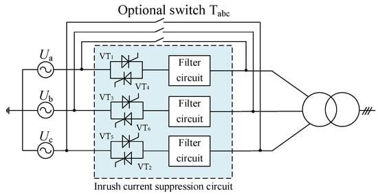
Figure 1.
Simplified circuit of the inrush current suppression circuit.
Figure 2 illustrates the phase-space trajectory of the state vector which comprises flux linkage and voltage and the two-dimensional phase plane diagram of the transformer core under three distinct operating conditions. The two-dimensional “flux linkage–voltage” phase plane diagram represents the projection of the phase-space trajectory onto the “flux linkage–voltage” plane. The three operating conditions are as follows: (1) direct no-load closing of the transformer (without an inrush current suppressor), (2) a soft starter with only an anti-parallel thyristor, and (3) a soft starter of the transformer employing the inrush current suppression circuit proposed in this paper. If the phase plane diagram is closed without saturation or resonance distortions, the flux is in steady state. The phase plane diagram presented in Figure 2a demonstrates that when the transformer is activated directly without any load, the per-unit value of the flux linkage reaches a maximum of 1.8 pu. This observation illustrates that the core magnetic flux experiences severe saturation and slight distortion during this specific period. When the transformer is soft-started solely using anti-parallel thyristors, the iron core remains unsaturated but accommodates numerous harmonic components throughout the start-up process (Figure 2b). However, through the utilization of the inrush suppressor proposed in this paper, which combines an anti-parallel thyristor with the filter, the soft-start process facilitates the successful alleviation of saturation and harmonic phenomena (Figure 2c). As depicted in Figure 2, when an inrush current occurs, the core magnetic flux becomes seriously saturated and slightly distorted. Under the action of the inrush current suppression circuit containing only anti-parallel thyristors, the magnetic flux undergoes significant harmonic distortion throughout the start-up process. By integrating an inrush current suppression circuit comprising an anti-parallel thyristor and a filter, the magnetic flux exhibits a gradual increment over time until it reaches a stable state without any harmonic distortion or saturation effects. Consequently, no inrush current is generated. Therefore, this article discusses the utilization of anti-parallel thyristors and filters in combination to achieve a soft start and suppress inrush current. Once the soft start process is complete, the optional switch can be engaged, simultaneously disabling the inrush current suppression circuit.
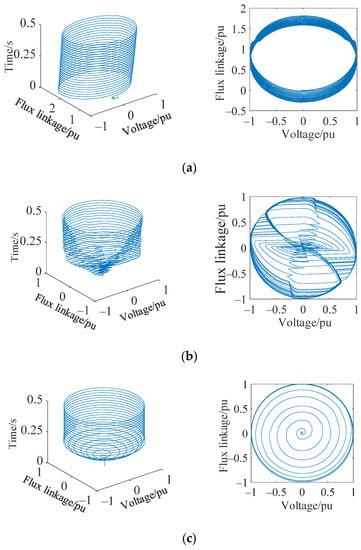
Figure 2.
Phase-space trajectory and its two-dimensional phase plane diagram of transformer under different conditions. (a) No inrush current suppression circuit; (b) An inrush current suppression circuit only containing anti-parallel thyristor; (c) An inrush current suppression circuit containing anti-parallel thyristor and filter.
3. Structure and Parameter Design of an Inrush Current Suppression Circuit
3.1. Inrush Current Suppression Loop and Its Control Method Based on Anti-Parallel Thyristors
In this paper, a soft starter adopts a three-phase structure with a star connection, as shown in Figure 3. The positive and negative half-waves of the load current are symmetrical, so the harmonics are mainly odd harmonics. At the same time, with the increase in harmonic frequency, the harmonic content decreases.
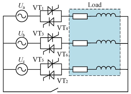
Figure 3.
A soft starter based on anti-parallel thyristor.
The current soft-start switch can achieve a gradual voltage rise to the steady-state value through either open-loop or closed-loop control strategies. In [12], a soft starter is implemented by employing open-loop control to prevent the occurrence of inrush current. The control target is an angle ramp function, which directly compares the voltage angle with a predetermined ramp to control the thyristor trigger delay angle β. This gradually changes from 180° to 0°, resulting in a steady voltage rise and the elimination of the need to switch on the electric arc furnace transformer, thereby preventing the generation of the inrush current. However, this direct control method is susceptible to disturbances such as grid voltage fluctuations and environmental changes. To address the aforementioned issue, a closed-loop control system for regulating the trigger delay angle is introduced, as illustrated in Figure 4.
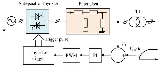
Figure 4.
Closed-loop control of soft-start switch.
It can be seen from Figure 4 that the transformer primary voltage obtained during the startup process is compared with the reference voltage. By using the PI control and PWM controller, the circuit generates the thyristor trigger pulse to regulate the conduction of the six thyristors in the soft-start switching circuit. This procedure enables the transformer voltage to increase gradually, as illustrated in Figure 5. The PWM controller works by comparing the triangular wave with the reference curve previously obtained to produce the thyristor’s trigger pulse that controls its conduction. Note that the figure shows only the conduction pulse of the forward thyristor for clarity.
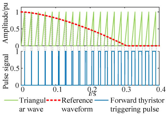
Figure 5.
The generation of thyristor triggering pulse.
3.2. Filter Structure of Inrush Current Suppression Circuit
Various passive high-order filter structures are presented in Figure 6. The passive damping scheme utilizing series resistance within the filter is a widely adopted solution for attenuating the resonant frequency and achieving stable system operation. The voltage transfer ratio for the LCLC high-order filter, incorporating equivalent series resistance, is evaluated as follows:
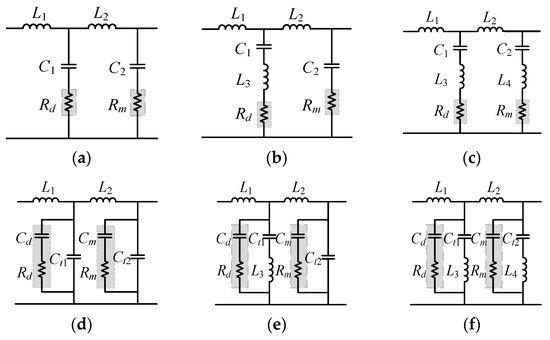
Figure 6.
Simplified structure diagram of high-order filters. (a) LCLC filter with series damping resistance; (b) Single trap filter with series damping resistance; (c) Double trap filter with series damping resistance; (d) LCLC filter with parallel RC damping; (e) Single trap filter with parallel RC damping; (f) Double trap filter with parallel RC damping.
The corresponding Bode plots of different filters are shown in Figure 7. It reveals that the LCLC filter exhibits the presence of two resonant frequencies. This characteristic poses a challenge as it diminishes the attenuation of low-order harmonics within the frequency range bracketed by the two resonant frequencies. Consequently, this situation hampers the effective filtering of low-order harmonics, thereby hindering the desired outcome of harmonic mitigation. The anti-parallel thyristor generates the largest proportion of the third and fifth harmonics. However, the LCLC filter current is insufficient in effectively attenuating the resonance frequencies associated with these harmonics. Although the series resistor R is capable of reducing the amplitude of the resonant frequency, it cannot improve the filtering effect on harmonics. Therefore, it is considered to replace the simple capacitor branch with the LC trap branch, and the harmonic filtering effects of adding a single trap branch (Trap1) and a double trap branch (Trap2) are analyzed in this paper, respectively. When adding only one trap branch, it is insufficient for effectively filtering out the third and fifth harmonics. Therefore, the use of two trap branches is necessary. The voltage transfer ratios of high-order single and double trap filters with equivalent series resistance are presented as follows:
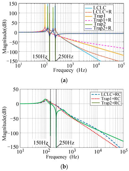
Figure 7.
Bode plots of transfer functions of different filters. (a) Without any damping or with damping provided by resistance R; (b) Damping achieved through an RC circuit.
It can be observed in Figure 7 that the high-order trap filter can mitigate resonance sharpness by connecting resistors in series, which is a simple and convenient method. However, this approach may lead to a reduction in the high-order harmonic filtering effect and an increase in system loss [13]. To address this issue, an alternative solution is proposed, which involves using a parallel RC damper instead of pure resistance to achieve the damping effect. As shown in the figure, this approach not only suppresses the harmonic amplitude, but also enhances the level of high-order harmonic attenuation, thereby achieving the required filtering effect [14]. Therefore, a high-order double trap filter with parallel RC damping is used in this paper, and its voltage transfer ratio is as follows:
Refer to Appendix A for transfer function coefficients. For the trap branch (L3Ct1) connected in parallel with the RC damper, the impedance characteristic of the branch is calculated as follows:
In high-order trap filter circuits, it is customary to select the sum of the two capacitors in the branch to be equal to the capacitance value of the branch in the LCLC high-order filter circuit [15]. This can be expressed as Ct1 + Cd = C1, Ct2 + Cm = C2 in Figure 6. Ct1 is defined as m1 times C1 (where 0.1 ≤ m1 ≤ 0.9), while Cd equals (1 − m1) times C1. Substituting these values into Formula (8) leads to a simplified expression as follows:
in which ωa and ωb represent the resonant frequency of the second-order undamped system and the turning frequency of the first-order differential circuit, respectively. On the other hand, ωc represents the undamped natural oscillation frequency and ζ represents the damping ratio of the oscillation link. The specific values for each variable are as follows:
The impedance amplitude characteristics of the trap branch circuit with parallel RC damping were obtained and compared with the conventional series impedance resonance frequency suppression method. The results are shown in Figure 8. It is evident from the figure that the parallel RC damper is superior to the traditional series impedance. This is because, on the one hand, the high-frequency slope attenuation characteristics can be maintained, and, on the other hand, the current is divided between the two branches, reducing the power loss of the device. However, a new resonant frequency is generated by the parallel RC damper, which must be taken into consideration during the parameter design process. This is elaborated on in the next section.
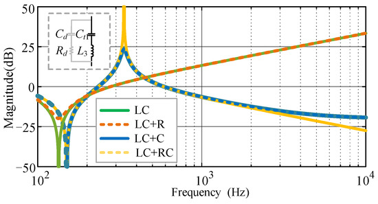
Figure 8.
Amplitude characteristics of different parallel impedance branches.
3.3. Optimization of Filter Parameters for Inrush Current Suppression Circuit
The design of the LCLC filter has been extensively covered in [16,17], and the trap filter has been thoroughly discussed in [18,19]. Therefore, this paper primarily focuses on optimizing the parameters of parallel RC damping.
After adding a parallel RC damper, a new resonant frequency frc may be generated following trap frequency (Figure 8). This phenomenon can lead to a sudden reduction in the amplitude attenuation within the frequency range spanning from the trap frequency to resonant frequency. Consequently, the resonance of this frequency band is weakened. This paper primarily focuses on the attenuation of the seventh and ninth harmonic components considering the implementation of two LC trap circuits as filtering mechanisms to suppress unwanted third and fifth harmonics. Figure 9 shows the variation of the amplitude of the seventh and ninth harmonic components with m1 and m2, where m1 and m2 are the ratios of the capacitance of the two trap branches to the capacitance of the RC damping RC branch.
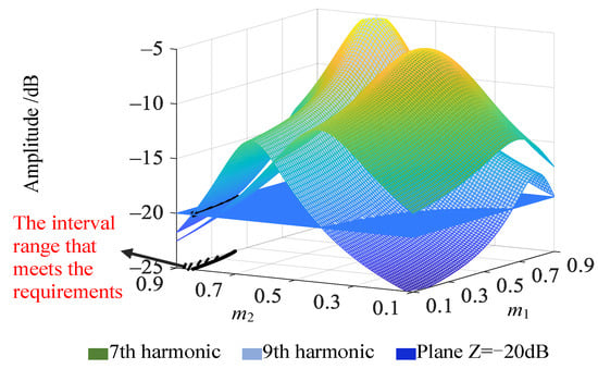
Figure 9.
The amplitude of the 7th and 9th harmonics at different m1 and m2.
The graphical representation in Figure 10 illustrates the peak values of all resonance points beyond the fifth harmonic when there are variations in the parameters m1 and m2. It shown that when m1 changes within a small value range, it has less influence on the peak value of the resonance point after the fifth harmonic, because the smaller the m1, the closer the resonance point caused by RC to the trap point, that is, when m1 is small (as shown in Figure 11), the resonance point is located between the third harmonic and the fifth harmonic, and it has no effect on the filtering of harmonic components after the fifth harmonic. Meanwhile, m2 directly affects the maximum peak value of the resonance point after the fifth harmonic. The larger the m2, the smaller the peak value. In summary, the values of m1 and m2 satisfying the minimum amplitude of the resonance point and the attenuation of the seventh and ninth harmonics greater than −20 dB are as follows:
m1 = [0.1, 0.3], m2 = 0.9.
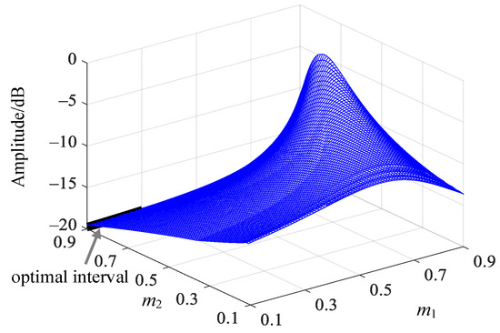
Figure 10.
The maximum amplitude of resonance point after 5th harmonic at different m1 and m2.
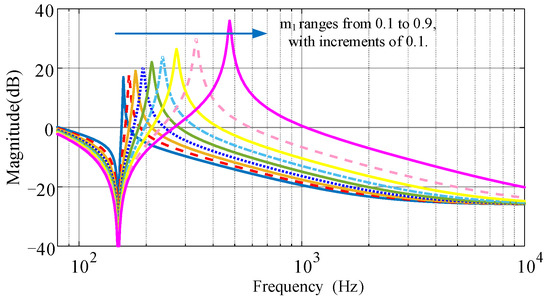
Figure 11.
Relation between the resonance point caused by the RC damper and m1.
In this paper, m1 = 0.2 and m2 = 0.9 are taken. Figure 12 depicts the variations in the peak values of the seventh and ninth harmonic components as well as the maximum peak value observed at the resonance point following the fifth harmonic in response to changes in Rd and Rm. The provided figure presents that when Rd = 0.1 and Rm = 0.5, the amplitude of the resonance point after the fifth harmonic reaches the minimum, and at the same time, the peak attenuation of the seventh and ninth harmonics is the largest, which is the required optimal point.
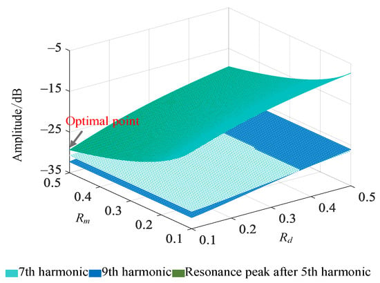
Figure 12.
The peak values of the 7th and 9th harmonics and the maximum peak value of the resonance point after the 5th harmonic when Rd and Rm change.
4. Discussion
In order to validate the effectiveness of the proposed inrush current suppression method described in this paper, a simulation model is developed using the Matlab/Simulink platform. The model’s structure is illustrated in Figure 13. During the transformer’s closing process without load or light load, the inrush current suppression circuit is activated. Once the start process is complete, the bypass switch is turned on, and the suppression circuit is deactivated simultaneously. Specific parameters of this model are as follows: the power supply voltage is set at 110 kV while the transformer voltage ratio is 110 kV/11 kV. The rated capacity is specified as 60 MVA. Additionally, the short-circuit voltage percentage is established at 9%, and the associated short-circuit loss is determined to be 420 kW.
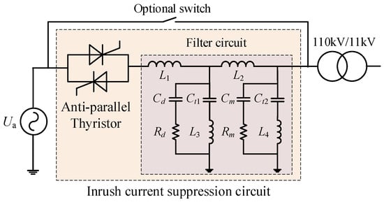
Figure 13.
A single-line diagram of simulation system.
The commonly used wiring modes of engineering transformers are YNd11, Yd11 and Yyn. Therefore, the suppression effect of the inrush suppressor under these three wiring modes of the transformer is analyzed in this paper. Table 1 presents the parameters employed in the filter circuit.

Table 1.
The parameters of high-order filter circuit.
4.1. YNd11 Wiring
Figure 14 displays the primary voltage and current waveforms during the no-load operation when employing the inrush current suppression circuit. To maintain clarity and simplicity, only the A-phase voltage and current waveforms are depicted in the following figures. The suppression circuit comprises an anti-parallel thyristor and a high-order trap filter with parallel RC damping. The figure demonstrates that the inrush current suppression circuit facilitates a gradual rise of the transformer voltage to its steady-state value. As the transformer voltage does not experience sudden changes, no transient magnetic flux is generated, preventing the transformer magnetic flux from entering the saturation region and producing magnetizing inrush current.
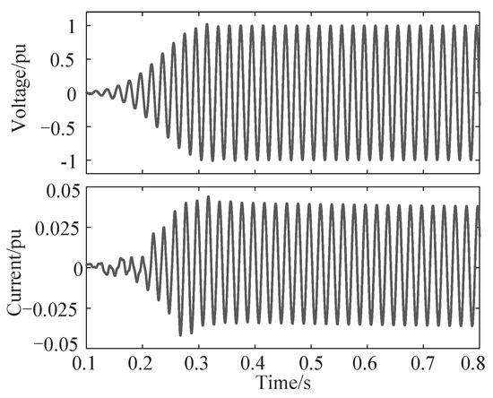
Figure 14.
The primary voltage and current waveforms of transformer at YNd11 wiring.
To compare the effects of various filter circuits, Figure 15 displays the changes in the effective value of the primary voltage when different inrush current suppression circuits are employed along with the corresponding voltage harmonic analysis when the voltage reaches half of the steady-state value. The filter circuits evaluated in this paper include an LCLC high-order filter with equivalent series resistance, a high-order double trap filter with equivalent series resistance, and a high-order double trap filter circuit with parallel RC damping.
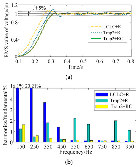
Figure 15.
Transformer voltage RMS and its harmonic analysis on different conditions. (a) RMS value of voltage; (b) Harmonic analysis of voltage.
In Figure 15, the transformer voltage reaches a stable value when it is close to t = 0.3 s. The LCLC high-order filter including the equivalent series resistance can filter out the 11th and above harmonic components, but it contains large 3rd, 5th and 7th harmonic components. This is because the LCLC filter generates two resonant frequencies, and the frequency components between or near the two resonant frequencies cannot be effectively filtered out. At this time, the voltage exhibits a total harmonic distortion rate of 25.2%, surpassing the permissible threshold set for satisfactory system operation. Moreover, a large number of harmonics leads to relatively large fluctuations after the transformer voltage reaches stability. For the high-order double trap filter with equivalent resistance, while the third and fifth harmonics can be filtered out effectively, there are still certain eleventh and higher harmonics present. This is due to the fact that the addition of the trap circuit to the advanced high-order trap double filter compromises the filtering effect on higher harmonic components. The total harmonic distortion rate of the voltage stands at 8.1%. While this represents a significant reduction compared to the LCLC high-order filter with equivalent series resistance, it still cannot meet the stability requirements. As shown in Figure 16, based on the phase-space trajectory diagram of transformer voltage and magnetic flux, it is evident that the magnetic flux may still be susceptible to saturation. This could lead to the generation of a certain amount of inrush current. In addition, the presence of harmonics results in a fluctuation of the transformer voltage even after it has reached a steady state. However, by implementing a high-order double trap filter with parallel RC damping, it is possible to effectively filter out all harmonic components while minimizing voltage fluctuations. This approach results in a total harmonic distortion rate of only 4.84%, which satisfies the system’s operational requirements.
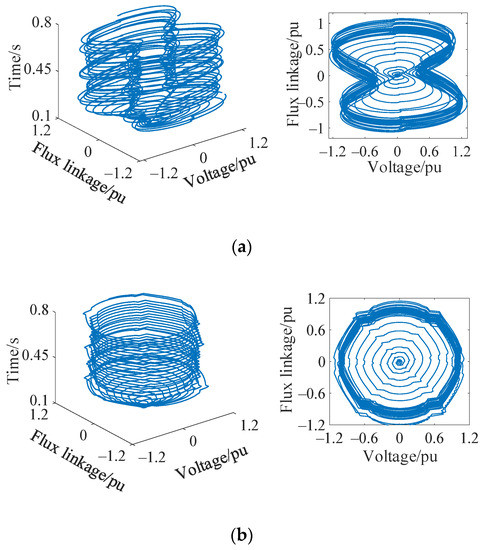
Figure 16.
Phase-space trajectory of voltage and flux of transformer in different filters. (a) LCLC high-order filter with equivalent series resistance; (b) High-order trap filter with equivalent series resistance.
4.2. Yd11 Wiring
For a transformer with a Yd11 connection, an inrush current suppression circuit consists of an anti-parallel thyristor and a high-order double trap filter with parallel RC damping is utilized. Figure 17 and Figure 18 depict the primary voltage and current waveforms and the phase-space trajectory of the transformer, respectively. Since the neutral point of the Yd11 wiring transformer is not grounded, the maximum harmonic component (third harmonic) generated by the anti-parallel thyristor lacks a circulation circuit. Therefore, the transformer current waveform is not affected by the third harmonic, resulting in a smoother change in the rising process of the primary side current compared to the YNd11 wiring. Additionally, the primary side current is less affected by harmonics. Moreover, it is possible for the magnetic flux of the transformer to increase gradually and reach a stable state without encountering saturation. Additionally, the implementation of an inrush current suppression circuit can effectively mitigate the occurrence of inrush current generation.
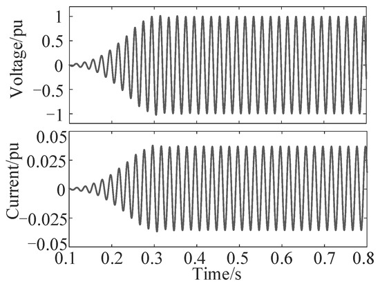
Figure 17.
The primary voltage and current waveforms of the transformer at Yd11 wiring.
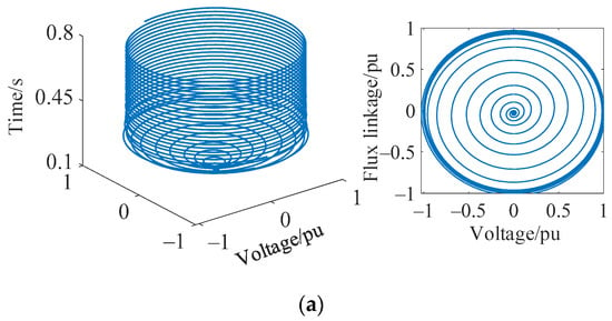
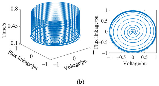
Figure 18.
Phase-space trajectories of transformer voltage and flux for different connections. (a) Yd11 wring; (b) Yyn wring.
4.3. Yyn Wiring
For transformers operating with the Yyn connection mode, an inrush current suppression circuit is employed during no-load switching. This circuit comprises an anti-parallel thyristor and a high-order trap filter with parallel RC damping. Figure 18 illustrates the phase-space trajectories of the voltage and magnetic flux in the transformer. The diagram illustrates that the primary winding of the transformer is interconnected in a configuration similar to Yd11, while the neutral points of both windings remain ungrounded. Therefore, the primary side voltage trend and the magnetic flux phase-space trajectory are comparable to those of Yd11, with both exhibiting a steady rise to the steady-state value and no saturation. As a result, the inrush current suppression circuit can effectively mitigate the generation of transformer inrush.
5. Conclusions
This paper investigates the underlying mechanism responsible for the occurrence of inrush current in transformers. Additionally, it presents a novel approach for mitigating inrush current through the utilization of a soft starter. The proposed principle involves the use of an inrush current suppression circuit, which consists of anti-parallel thyristors and high-order filters, to ensure a steady rise of primary voltage to its steady-state value, thus eliminating the generation of an inrush current. To verify the effectiveness of this principle, a circuit model for the inrush current suppression was developed using Matlab/Simulink. The model was utilized to conduct simulations of the voltage, current, and flux characteristics exhibited by a three-phase transformer with different wiring configurations. The simulation results indicate that:
- A high-order double trap filter with a parallel RC damping is proposed to mitigate the negative effects of many harmonics generated during the conduction process of antiparallel thyristors. This filter addresses the limitations of the LCLC high-order filter, which cannot filter out the third and fifth harmonic components. By contrast, the high-order trap filter with equivalent series resistance can successfully filter out these components. However, it should be noted that the filtering effect of the 11th and higher harmonic components is compromised.
- The inrush suppression method eliminates the need to consider the impact of residual flux and transformer neutral point grounding mode. It is applicable to various transformer structures and wirings, which makes it highly versatile.
The inrush suppression method, however, leads to an escalation in costs and control complexities, while the potential impact on future engineering applications necessitates further investigation.
Author Contributions
Conceptualization, C.L.; formal analysis, C.L. and H.L.; investigation, Y.Y.; methodology, C.L.; software, W.L. and H.L.; validation, Y.Y., W.L. and H.L.; writing—original draft, C.L. and W.L.; writing—review and editing, Y.Y. All authors have read and agreed to the published version of the manuscript.
Funding
This work was supported in part by the Science and Technology Research Program of Chongqing Municipal Education Commission (Grant No. KJQN202201119).
Data Availability Statement
Data are contained within the article.
Conflicts of Interest
The authors declare no conflict of interest.
Appendix A
The transfer function coefficients in Formula (7) are showed as follows:
in which
References
- Murugan, S.K.; Simon, S.P.; Nayak, P.S.R.; Sundareswaran, K.; Padhy, N.P. Power transformer protection using chirplet transform. IET Gener. Transm. Distrib. 2016, 10, 2520–2530. [Google Scholar] [CrossRef]
- Naseri, F.; Kazemi, Z.; Arefi, M.M.; Farjah, E. Fast Discrimination of Transformer Magnetizing Current from Internal Faults: An Extended Kalman Filter-Based Approach. IEEE Trans. Power Deliv. 2018, 33, 110–118. [Google Scholar] [CrossRef]
- Guillen, D.; Esponda, H.; Vazquez, E.; Idárraga-Ospina, G. Algorithm for transformer differential protection based on wavelet correlation modes. IET Gener. Transm. Distrib. 2016, 10, 2871–2879. [Google Scholar] [CrossRef]
- Chen, Y.H.; Yeh, M.Y.; Cheng, P.T.; Liao, J.C.; Tsai, W.Y. An Inrush Current Reduction Technique for Multiple Inverter-Fed Transformers. IEEE Trans. Ind. Appl. 2014, 50, 474–483. [Google Scholar] [CrossRef]
- Chiesa, N.; Hoidalen, H.K. Novel approach for reducing transformer inrush currents: Laboratory measurements, analytical interpretation and simulation studies. IEEE Transac. Power Deliv. 2010, 25, 2609–2616. [Google Scholar] [CrossRef]
- Mitra, J.; Xu, X.F.; Benidris, M. Reduction of Three-Phase Transformer Inrush Currents Using Controlled Switching. IEEE Trans. Ind. Appl. 2020, 56, 890–897. [Google Scholar] [CrossRef]
- Peng, F.; Gao, H.L.; Liu, Y.Q. Transformer sympathetic inrush characteristics and identification based on substation-area information. IEEE Trans. Power Deliv. 2017, 33, 218–228. [Google Scholar] [CrossRef]
- Huo, C.; Wang, Y.; Zhao, Z.; Liu, C. Residual flux measurement of the single-phase transformer based on transient current method. IEEE Trans. Appl. Supercond. 2020, 30, 1–5. [Google Scholar] [CrossRef]
- Pan, Y.; Yin, X.; Zhang, Z.; Liu, B.; Wang, M.; Yin, X. Three-Phase Transformer Inrush Current Reduction Strategy Based on Prefluxing and Controlled Switching. IEEE Access 2021, 9, 38961–38978. [Google Scholar] [CrossRef]
- Cano-González, R.; Bachiller-Soler, A.; Rosendo-Macías, J.A.; Álvarez-Cordero, G. Inrush current mitigation in three-phase transformers with isolated neutral. Electr. Power Syst. Res. 2015, 121, 14–19. [Google Scholar] [CrossRef]
- Fang, S.; Ni, H.; Lin, H.; Ho, S.L. A novel strategy for reducing inrush current of three-phase transformer considering residual flux. IEEE Trans. Ind. Electron. 2016, 63, 4442–4451. [Google Scholar] [CrossRef]
- Pires, I.A.; Machado, A.A.P.; Cardoso Filho, B.D. Mitigation of electric arc furnace transformer inrush current using soft-starter-based controlled energization. IEEE Trans. Ind. Appl. 2018, 54, 3909–3918. [Google Scholar] [CrossRef]
- Pena-Alzola, R.; Roldan-Perez, J.; Bueno, E.; Huerta, F.; Campos-Gaona, D.; Liserre, M.; Burt, G. Robust Active Damping in LCL-Filter-Based Medium-Voltage Parallel Grid Inverters for Wind Turbines. IEEE Trans. Ind. Appl. 2018, 33, 10846–10857. [Google Scholar] [CrossRef]
- Wu, W.; He, Y.; Tang, T.; Blaabjerg, F. A new design method for the passive damped LCL and LLCL filter-based single-phase grid-tied inverter. IEEE Trans. Ind. Electron. 2013, 60, 4339–4350. [Google Scholar] [CrossRef]
- Beres, R.N.; Wang, X.; Blaabjerg, F.; Liserre, M.; Bak, C.L. Optimal design of high-order passive-damped filters for grid-connected applications. IEEE Trans. Power Electron. 2016, 31, 2083–2098. [Google Scholar] [CrossRef]
- Thompson, I.V.; Brennan, P.V. Fourth-order PLL loop filter design technique with invariant natural frequency and phase margin. IEE Proc.-Circuit Device Syst. 2005, 152, 103–108. [Google Scholar] [CrossRef]
- Tang, N.; Nguyen, B.; Molavi, R.; Mirabbasi, S.; Tang, Y.; Zhang, P.; Kim, J.; Pande, P.P.; Heo, D. Fully integrated buck converter with fourth-order low-pass filter. IEEE Trans. Power Electron. 2017, 32, 3700–3707. [Google Scholar] [CrossRef]
- Khan, A.; Gastli, A.; Ben-Brahim, L. Modeling and control for new LLCL filter based grid-tied PV inverters with active power decoupling and active resonance damping capabilities. Electr. Power Syst. Res. 2018, 155, 307–319. [Google Scholar] [CrossRef]
- Fang, J.; Li, X.; Yang, X.; Tang, Y. An integrated trap-LCL filter with reduced current harmonics for grid-connected converters under weak grid conditions. IEEE Trans. Power Electron. 2017, 32, 8446–8457. [Google Scholar] [CrossRef]
Disclaimer/Publisher’s Note: The statements, opinions and data contained in all publications are solely those of the individual author(s) and contributor(s) and not of MDPI and/or the editor(s). MDPI and/or the editor(s) disclaim responsibility for any injury to people or property resulting from any ideas, methods, instructions or products referred to in the content. |
© 2023 by the authors. Licensee MDPI, Basel, Switzerland. This article is an open access article distributed under the terms and conditions of the Creative Commons Attribution (CC BY) license (https://creativecommons.org/licenses/by/4.0/).