Article

Microwave Humidity Sensor for Early Detection of Sweat and Urine Leakage

CIMITEC, Departament d’Enginyeria Electrònica, Universitat Autònoma de Barcelona, 08193 Bellaterra, Spain
*
Authors to whom correspondence should be addressed.
Electronics 2023, 12(10), 2276; https://doi.org/10.3390/electronics12102276
Submission received: 24 April 2023 / Revised: 12 May 2023 / Accepted: 16 May 2023 / Published: 18 May 2023
(This article belongs to the Special Issue Emerging Electronic Technologies for Biomedical Applications)

Abstract

:
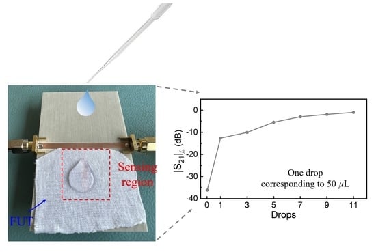
A planar microwave sensor devoted to the detection of humidity in underwear and clothes in general is proposed. The ultimate goal of the sensor is to detect the presence of liquids in fabrics, which is of interest to aid patients who suffer from certain pathologies, such as hyperhidrosis and enuresis. The main target in the design of the sensor, considering the envisaged application, is simplicity. Thus, the sensor operates at a single frequency, and the working principle is the variation in the magnitude of the transmission coefficient of a matched line loaded with an open-ended quarter-wavelength sensing stub resonator. The stub, which must be in contact with the so-called fabric under test (FUT), generates a notch in the transmission coefficient with a resonance frequency that depends on the humidity level of the fabric. By designing the stub with a moderately high-quality factor, the variation in the resonance frequency causes a significant change in the magnitude level at the operating frequency, which is the resonance frequency when the sensing stub is loaded with the dry fabric, and the presence of liquid can be detected by means of an amplitude detector. A prototype device is proposed and experimentally validated. The measured change in the magnitude level by simply depositing one 50 μL drop of water in the FUT is roughly 25 dB.

Graphical Abstract

1. Introduction

Planar microwave technology is of the highest interest for the implementation of a wide variety of sensors [1,2]. Among their advantages, planar microwave sensors exhibit low cost and profile, and they can be implemented in many different types of substrates, including rigid substrates (such as low-cost FR4 or low-loss microwave substrates), or flexible substrates (including polymeric substrates, organic substrates, e.g., paper or fabric, among others). Planar microwave sensors can be fabricated by means of either subtractive (e.g., photoetching or milling) or additive (e.g., inkjet printing, screen printing, or 3D printing) processes. Moreover, planar microwave sensors are compatible with many other technologies such as microfluidics, micromachining, textiles, etc., and can be equipped with functional films that make these sensors of interest in applications as diverse as liquid sensing [3,4,5,6,7], bio-sensing [8,9], gas sensing [10,11,12,13,14,15,16], wearables [17,18,19,20,21,22], measurement of physical variables (such as temperature or ambient humidity [23,24,25]), etc. The dielectric characterization of materials, namely permittivity measurements [7], [26,27,28], represents the archetypal application of planar microwave sensors. Microwave sensors are highly sensitive to the complex permittivity of the material surrounding the sensing element, typically implemented as a transmission line section or a planar resonator. Thus, the permittivity of such material, or any other variable related to it, can be retrieved. The sensor to be developed in this paper is based on the change in the permittivity of fabric (the fabric under test, FUT) caused by liquid absorption (sweat or urine in real environments). Such change will modify the electrical characteristics of the sensitive element (capacitance, characteristic impedance, electrical length, etc.), which in turn will generate a variation in the output variable of the sensor (resonance frequency, quality factor, group delay, phase and/or magnitude of the reflection or transmission coefficient, etc.).
Planar microwave sensors can be categorized according to the output variable as frequency-variation sensors [7,8,9,26,27,28,29,30,31,32,33,34,35], frequency-splitting sensors [4,22,36,37,38,39], magnitude-variation sensors (or coupling-modulation sensors [40,41,42,43,44,45,46,47,48,49,50,51]), and phase-variation sensors [52,53,54,55,56,57,58,59,60,61,62,63,64,65,66,67,68,69]. Nevertheless, in some cases, two combined output variables are used. For example, resonant sensors [7,26,27,28] are commonly used to determine the complex permittivity of materials. These sensors exploit variations in resonance frequency, which are primarily correlated with the dielectric constant of the material under test, as well as variations in the magnitude of the notch or peak in the frequency response, which are primarily correlated with the loss tangent. While frequency-variation and frequency-splitting sensors are robust against electromagnetic interference (EMI) and noise due to their reliance on frequency measurements, these sensors require wideband sweeping interrogation signals for sensing, which must cover the output dynamic range. The need for such signals complicates the implementation of associated electronics in real-world environments. The solution to this issue is given by the so-called single-frequency sensors, fed by a harmonic (single-tone) interrogation signal. Coupling-modulation and phase-variation sensors belong to this class of sensors. Phase-variation sensors, additionally, are robust against EMI and noise (similar to frequency-variation sensors) and are very attractive for sensing. Nevertheless, retrieving the phase of either the reflection or the transmission coefficient in the operational environment (i.e., without the use of a vector network analyzer), in general, is not as simple as inferring the magnitude [70]. Magnitude measurements are more prone to the effects of EMI and noise, but the simplicity of the associated electronics is important in certain applications, in particular the intended application in this work (the detection of liquid absorption in fabric). Note that a simple amplitude detector suffices to convert the magnitude of the transmission coefficient in a voltage variable (an easy measurable magnitude) [49,50,51]. Thus, in this present paper, we exploit the magnitude of the transmission coefficient at a single frequency for sensing, with an eye towards sensor simplicity.
The sensing device proposed in this work is a resonant sensor, where the sensitive element is an open-ended quarter-wavelength stub resonator that must be in contact with the FUT and connected to a matched transmission line. The output variable is the magnitude of the transmission coefficient at the operating frequency, which is the resonance frequency of the open-ended stub when it is loaded with the dry FUT. This frequency is indicated by a notch in the transmission coefficient. When the FUT absorbs liquid (urine or sweat in a real scenario), the frequency response shifts downwards (because the effective dielectric constant “seen” by the stub increases), and the magnitude of the transmission coefficient at the operational frequency varies. Thus, liquid absorption by the fabric can be detected with this method.
This work is organized as follows. Section 2 presents the proposed humidity sensor and the working principle in detail. The specific sensor design is the subject of Section 3, where validation at the simulation level is included. Experimental validation is carried out in Section 4 by considering fabric and different levels of water absorption. In Section 5, some comparisons are made between the sensor proposed in this work and those in the references. Finally, the main conclusions of this work are highlighted in Section 6.

2. The Proposed Sensor and Working Principle

The topology and perspective view of the proposed sensor is depicted in Figure 1. It consists of a transmission line loaded with an open-ended quarter-wavelength stub resonator, the sensitive element. The transmission line is matched to the reference impedance of the ports (Z0 = 50 Ω), namely its characteristic impedance is Zc = Z0. The design variables are the length and width of the sensitive stub. The length determines the resonance frequency (notch frequency) of the sensor, whereas the width is related to the characteristic impedance of the stub, Zs. In turn, Zs is the key parameter that determines the quality factor of the stub resonator. An extreme (i.e., very high or very low) quality factor should be avoided. The reason is that if the quality factor is very small, a soft variation in the magnitude of the transmission coefficient at the resonance of the stub loaded with the dry FUT (the reference FUT) is expected. By contrast, if the quality factor is very high, tuning to the resonance frequency of the stub when it is loaded with the dry FUT is not absent of certain difficulty. Thus, a tradeoff is necessary.
The working principle of the sensor is the shift in the frequency response (magnitude of the transmission coefficient) when the FUT absorbs a certain liquid. This modifies the dielectric constant of the FUT, and the resonance frequency of the stub shifts down (Figure 2). As a consequence, the magnitude of the transmission coefficient at f0 (the resonance frequency of the stub loaded with the reference, dry FUT), varies (increases), and liquid absorption is thereby detected. The output variable in the proposed sensor is, thus, the magnitude of the transmission coefficient at f0, whereas the input variable is the dielectric constant of the FUT and is intimately related to the level of liquid absorption by the FUT. In the prototype to be discussed later, liquid absorption is achieved by depositing water drops on top of the FUT, with the result of a change in the dielectric constant of the FUT.

3. Sensor Design

The proposed sensor is designed to exhibit a resonance frequency of 2 GHz when the stub is in contact with the air (bare sensor). The frequency of operation f0 is expected to be slightly smaller since it should be tuned to the resonance frequency of the stub loaded with the reference (dry) FUT. Nevertheless, the dielectric constant of fabric is expected to be very close to that of the air, and, hence, f0 should not vary extremely from the resonance frequency of the bare sensor. The considered substrate for sensor implementation is the Rogers 4003C substrate with a dielectric constant εr = 3.55, thickness h = 1.524 mm, and loss factor tanδ = 0.0022. With the considered substrate, the width of the 50-Ω host line is W = 3.36 mm. For the stub, let us consider three different values of the characteristic impedance, Zs,1 = 25 Ω, Zs,2 = 50 Ω, and Zs,3 = 70 Ω. The corresponding widths, with the considered substrate, are Ws,1 = 9.04 mm, Ws,2 = 3.36 mm, and Ws,3 = 1.85 mm. We have adjusted the length of the open stub in all 3 cases in order to generate a notch (bare sensor) at 2 GHz, as indicated. The lengths are not identical, since the effective dielectric constant of the stub depends on its width, but the values are very similar (ls,1 = 21.03 mm, ls,2 = 22.15 mm, and ls,3 = 22.45 mm). The responses of the bare sensors (magnitude of the reflection and transmission coefficient) for all three cases, inferred from full wave electromagnetic simulation using the ANSYS HFSS 19.0 commercial software, are depicted in Figure 3. The length of the host line has been set to 50 mm in all cases, but this length does not affect the magnitude of the reflection and transmission coefficient, since the impedance of that line coincides with the reference impedance of the ports. The stop band bandwidth, or quality factor of the stub, varies with its characteristic impedance. According to the previously mentioned tradeoff, we consider that the stub with impedance Zs,3 = 70 Ω (and width Ws,3 = 1.85 mm) is appropriate for our purposes since it exhibits a moderate quality factor. Therefore, the sensor will be implemented by considering such stub impedance and width.
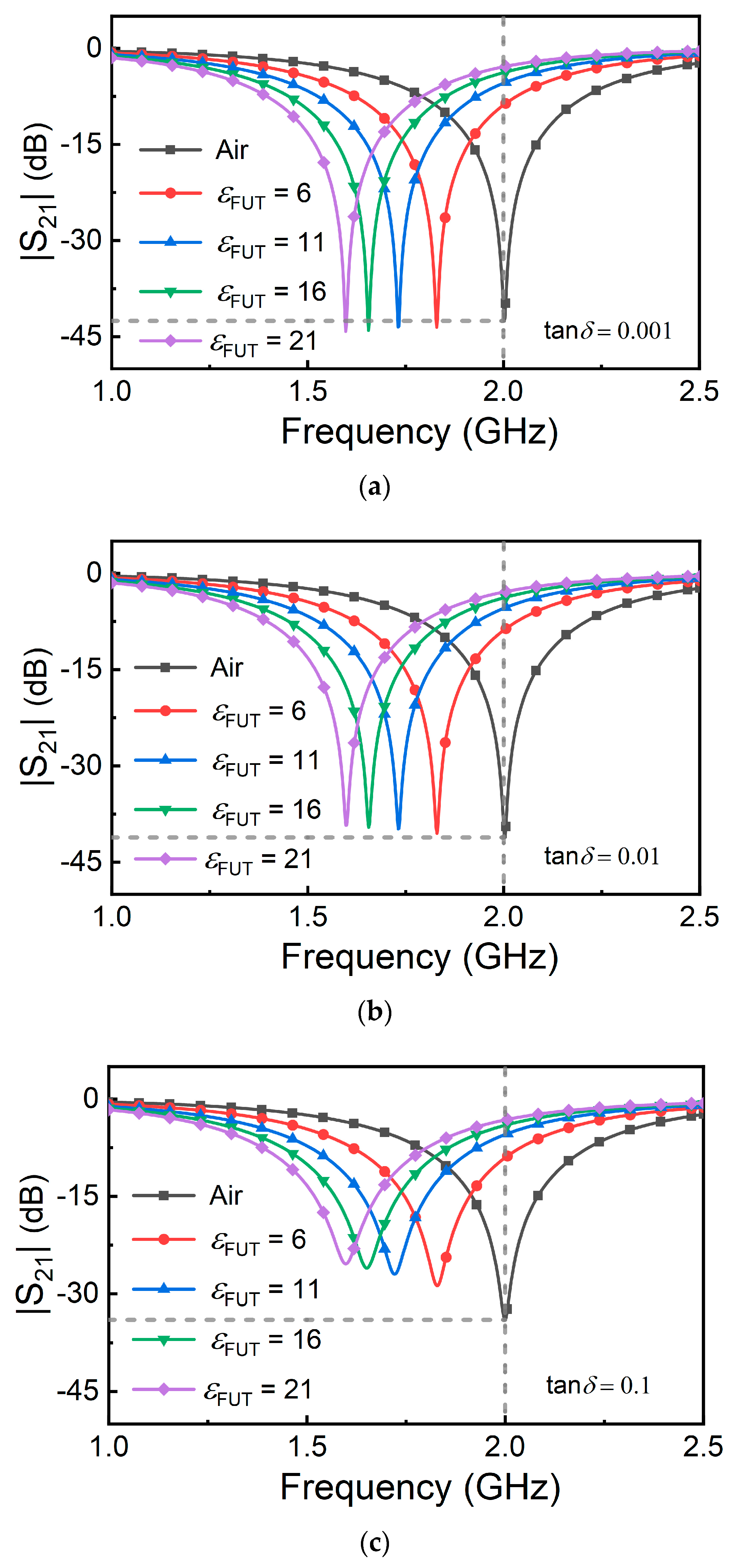
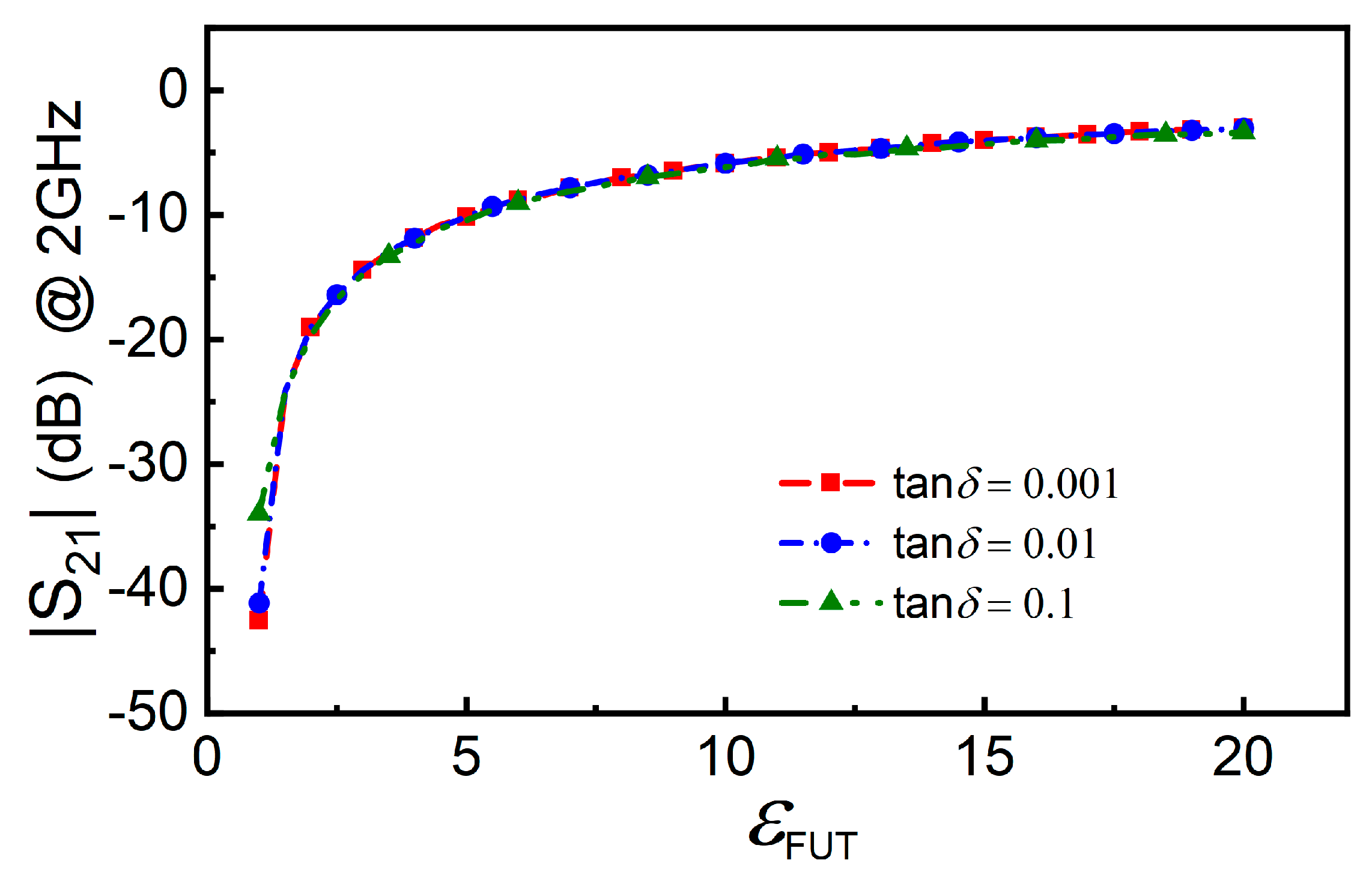
Before experimental validation (left for the next section), let us anticipate the behavior of the sensor by electromagnetic simulation. For this purpose, let us consider that the sensing region is coated with a hypothetical material, with a varying dielectric constant, that emulates the FUT with different levels of liquid absorption. The considered thickness of that material is 0.3 mm since this thickness can be comparable to the one of fabric, such as underwear or clothes made of cotton. We have varied the dielectric constant of the FUT between εFUT = 1 (the value of air and expected to be very close to the dielectric constant of dry fabric) and εFUT = 21 (a relatively high value, as expected in situations where significant liquid absorption by the fabric occurs). Note that this maximum value of εFUT is somewhat arbitrary, since the actual value (in a real environment) is expected to depend on the specific liquid (sweat, urine, etc.). Nevertheless, it is a representative value providing a reasonable input dynamic range, useful to qualitatively predict the behavior of the sensor. We have carried out the simulations parametrized by the loss tangent of the FUT (by considering values of 0.001, 0.01 and 0.1). The simulated frequency responses are depicted in Figure 4, whereas Figure 5 depicts the dependence of the magnitude of the transmission coefficient at f0 (2 GHz) with the dielectric constant of the FUT for the different considered values of the loss tangent. According to Figure 5, the transmission coefficient at f0 varies significantly with εFUT for the 3 considered values of the loss tangent of the FUT. Nevertheless, the variation (and hence the sensitivity) is more pronounced for small values of the loss tangent. Note also that the sensitivity for small values of εFUT degrades as the loss tangent of the FUT increases. However, for moderate and high values of εFUT, the sensitivity does not depend on the loss tangent of the FUT. These simulation results reveal that the intended sensor can work to detect the presence of liquid absorption in fabric, an aspect to be discussed in the next section, where the sensor is experimentally validated.

4. Experimental Validation

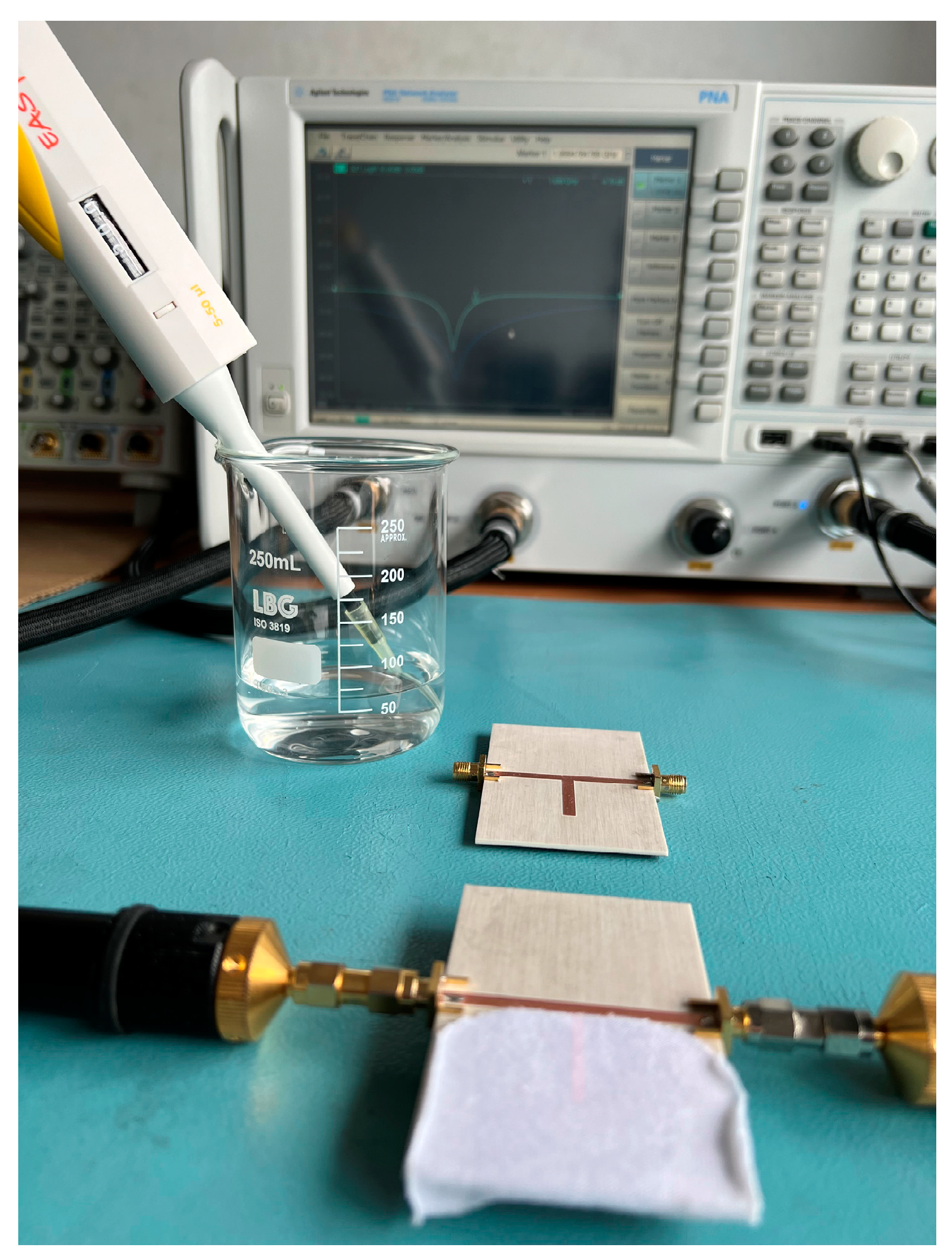
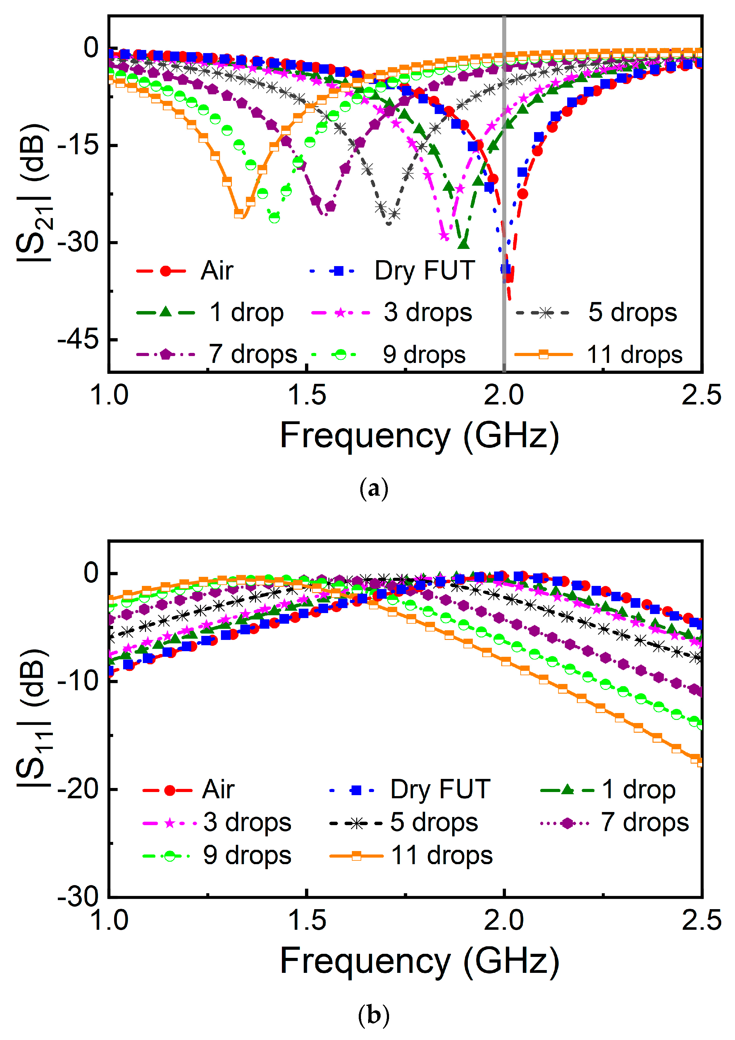
For experimental validation, we have fabricated the sensor with dimensions and a substrate corresponding to the simulations of Figure 4 and Figure 5. The sensor was fabricated by means of the LPKF H100 drilling machine, available in our laboratory (the photograph is depicted in Figure 6). The measured frequency response of the bare sensor and one of the sensors loaded with the reference (dry) FUT, depicted in Figure 7 and inferred by means of the Keysight N5221A vector network analyzer, reveal that the dielectric constant of the dry FUT is very similar to the one of air, as anticipated (note that the responses are very similar). Indeed, the notch frequency of the sensor loaded with the dry FUT is slightly inferior to the one of the bare sensors, and it is the considered operating frequency of the sensor, f0 = 2 GHz. The FUT is a piece of cotton underwear, which has been cut in a rectangular shape to accommodate it to the dimensions of the sensing region.
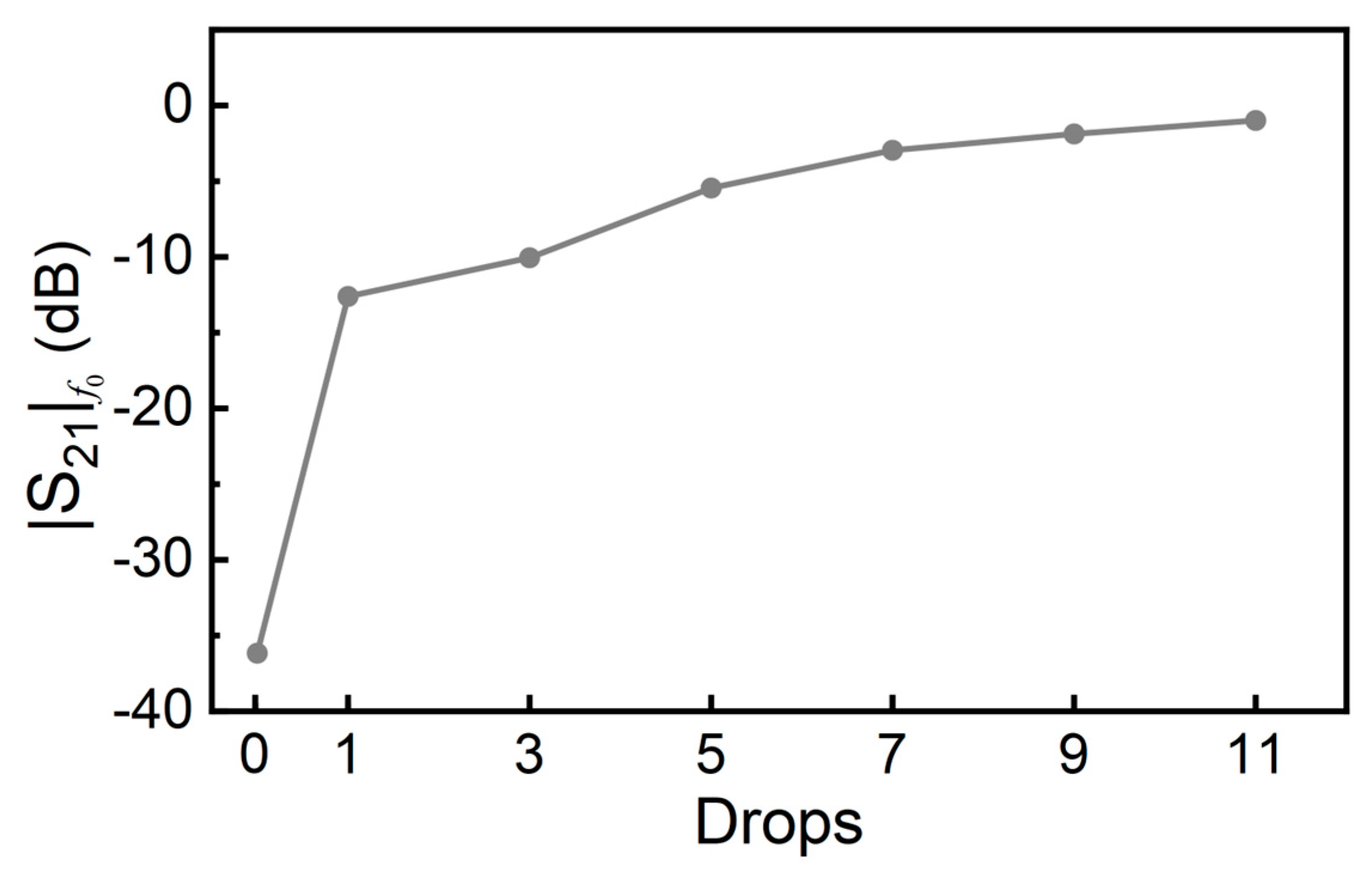
Next, we have emulated sweat or urine absorption by the fabric by dropping DI water with a pipette on top of it. Specifically, we have sequentially added a water drop on top of the fabric and made the measurement of the frequency response after each drip. The results, also included in Figure 7, reveal that, as the number of accumulated drops in the fabric increase, the frequency response progressively shifts down. The result is an increase of the magnitude of the transmission frequency at f0, | S 21 | f 0 . The variation of | S 21 | f 0 with the accumulated number of drops is depicted in Figure 8. (It follows a similar trend to that of Figure 5). According to the results of Figure 8, the presence of water in the fabric can be detected, and therefore the sensor is experimentally validated.

5. Discussion

Let us next put in context the proposed sensor as compared to other approaches to detect/measure humidity. Let us start by mentioning that the sensor of this work is based on microwave technology. One of the advantages of microwaves for sensing is their inherent wireless connectivity, which can be of interest within the framework of the internet of things (IoT), and particularly in the field of smart health, where retrieving information wirelessly is necessary in many cases. Microwave sensors are canonically permittivity sensors, and for this main reason the proposed sensor is based on permittivity variations of the FUT rather than on the variation of other variables, such as conductivity. The reported device is a proof-of-concept demonstration of the potential of the approach to detect the presence of liquid in fabric. We leave for future work the implementation of the humidity sensor directly on fabric, with the idea of replacing the rigid microwave substrate considered in this work with a textile substrate (that can be part of the underwear to detect urine leakage or the presence of sweat). It is also left for future work the implementation of the whole sensor, including the associated electronics for signal generation and for signal processing. In the prototype presented in this paper, the main interest has been focused on the microwave module of the sensor rather than on the associated electronics, and we have obtained the sensor response with a vector network analyzer. In real scenarios, such response can be inferred by means of an envelope (amplitude) detector connected to the output port of the host line, as has been demonstrated in several papers (e.g., in [51]). On the other hand, the feeding (harmonic) signal can be generated by means of a voltage-controlled oscillator (VCO) managed by a microcontroller.
We should mention that, despite the fact that the proposed sensor detects the presence of liquid in fabric, it cannot be considered a microwave liquid sensor. Liquid sensors are mainly focused on the characterization of the complex dielectric constant of a certain liquid under study [4,5,6,7] or on the determination of the composition of liquid mixtures [51,57,71,72,73,74,75,76,77,78,79,80,81]. Such sensors are typically implemented by means of fluidic channels [51,57,71,72,73,74,75,76,77]. However, sensing structures based on holders [7] or submersible devices [82,83,84,85] have also been reported. In the sensor reported in this paper, the level of humidity in the fabric due to absorption was detected. Thus, it can be considered a humidity sensor. There are several reported sensors devoted to the measurement of humidity [86,87,88,89,90,91] but mostly devoted to measuring ambient humidity. In most cases, such sensors utilize functional materials, e.g., Kapton [88], polyvinyl alcohol (PVA) [86], polyethylene terephthalate (PET) [87], etc., with the dielectric constant very sensitive to the humidity level, or nanostructures (e.g., silicon nanowires) [89], or halloysite nanotubes (HNTs) [90]. Nevertheless, examples of humidity sensors devoted to detecting the presence of liquids in fabric have also been reported. In these cases, functional materials are not needed, since, in general, fabrics absorb liquids, generating a significant change in the permittivity. One example is the sensor reported in [22], implemented in a fabric substrate. The functionality of that sensor was demonstrated in [22]. The main advantage of the sensor of Figure 6, over the sensor presented in [22], is operation at a single frequency, contrary to the sensor in [22], based on frequency splitting. Moreover, the sensor of Figure 6 is very simple, being based on a stub, the sensing element, loading a host transmission line. In [92,93], sensors devoted to detecting urine incontinence, based on changes in the conductivity of an interdigital electrode, were proposed. Capacitive sensors integrated in underwear with embroidered textile technology were proposed in [94,95]. The sensitive elements of these sensors [92,93,94,95] are based on interdigital conductive patterns, which occupy a much larger area and are more complex to fabricate than the sensitive element in this work, i.e., merely an open stub with quarter wavelength. In addition, in [92], the minimum amount of humidity (liquid) of the sensor that could be detected was 0.1 mL, corresponding to 11.71 MΩ, compared with 15.52 MΩ when it was dry. While in this work, the minimum amount of humidity that could be measured was 50 µL, corresponding to –12 dB at 2 GHz (operating frequency), compared with –36 dB at 2 GHz when it was dry. Although the output variables are different, but the sensor in this work is superior for the detection of a tiny amount of liquid absorption, given the fact that, in [94,95] the aim was to detect leakage levels when the diaper was full.

6. Conclusions

In conclusion, it has been experimentally demonstrated that humidity in fabric (particularly, the cotton of underwear clothes) can be detected by means of a simple planar microwave sensor consisting in a microstrip line loaded with an open-ended quarter-wavelength resonant stub, the sensitive element. For simplicity, it has been considered that the output variable is the magnitude of the transmission coefficient measured at a specific frequency, i.e., the resonance frequency of the stub when it is coated with the dry fabric. Thus, the sensor works at a single frequency, an important aspect for operation in real environments, where vector network analyzers used at the laboratory level should be replaced with signal generators and detectors (in the considered structure, a narrow band voltage-controlled oscillator and an amplitude detector would suffice). According to the obtained experimental results, a single drop (with an estimated volume of 50 μL) generates a magnitude variation in the transmission coefficient of the sensor at the operating frequency of roughly 25 dB, more than enough to detect the presence of small amounts of water in fabric. Thus, with these results, it can be envisaged that the reported sensor can be applied to the detection of sweet in fabric or urine leakage in underwear. In future studies, the focus will be the direct implementation of the sensor in a fabric substrate, which is more compatible with the intended application.

Author Contributions

Conceptualization, F.M.; funding acquisition, F.M.; methodology, L.S. and P.V.; project administration, F.M.; software, L.S. and P.V.; supervision, F.M.; validation, L.S., P.V., P.C. and J.M.-E.; writing—original draft, L.S. and F.M.; writing—review and editing, L.S., P.V., P.C., J.M.-E. and F.M. All authors have read and agreed to the published version of the manuscript.

Funding

This work was supported by MCIN/AEI 10.13039/501100011033, Spain, through projects PID2019-103904RB-I00 (ERDF European Union) and PDC2021-121085-I00 (European Union Next Generation EU/PRTR), by Generalitat de Catalunya through project 2021SGR-00192, and by ICREA. P. Casacuberta acknowledges the Ministerio de Universidades, Spain, for the FPU grant (Ayudas para la formación de profesorado universitario), ref. FPU20/05700. L. Su acknowledges the Juan de la Cierva Program for their support through the project IJC2019-040786-I.

Data Availability Statement

This article contains the necessary data to verify the results (circuit dimensions and substrate used, as well as setup conditions). Text-based files containing the S-parameter data obtained in simulations and measurements can be requested to the corresponding author.

Conflicts of Interest

The authors declare no conflict of interest. The funders had no role in the design of the study; in the collection, analyses, or interpretation of data; in the writing of the manuscript; or in the decision to publish the results.

References

  1. Martín, F.; Vélez, P.; Muñoz-Enano, J.; Su, L. Planar Microwave Sensors; Wiley/IEEE Press: Hoboken, NJ, USA, 2022. [Google Scholar]
  2. Abdolrazzaghi, M.; Nayyeri, V.; Martín, F. Techniques to Improve the Performance of Planar Microwave Sensors: A Review and Recent Developments. Sensors 2022, 22, 6946. [Google Scholar] [CrossRef] [PubMed]
  3. Grenier, K.; Dubuc, D.; Poleni, P.E.; Kumemura, M.; Toshiyoshi, H.; Fujii, T.; Fujita, H. New Broadband and Contact Less RF/Microfluidic Sensor Dedicated to Bioengineering. In Proceedings of the 2009 IEEE MTT-S International Microwave Symposium Digest, Boston, MA, USA, 7–12 June 2009; pp. 1329–1332. [Google Scholar]
  4. Vélez, P.; Su, L.; Grenier, K.; Mata-Contreras, J.; Dubuc, D.; Martín, F. Microwave Microfluidic Sensor Based on a Microstrip Splitter/Combiner Configuration and Split Ring Resonators (SRRs) for Dielectric Characterization of Liquids. IEEE Sens. J. 2017, 17, 6589–6598. [Google Scholar] [CrossRef]
  5. Ebrahimi, A.; Scott, J.; Ghorbani, K. Ultrahigh-Sensitivity Microwave Sensor for Microfluidic Complex Permittivity Measurement. IEEE Trans. Microw. Theory Tech. 2019, 67, 4269–4277. [Google Scholar] [CrossRef]
  6. Chuma, E.L.; Iano, Y.; Fontgalland, G.; Roger, L.L.B. Microwave Sensor for Liquid Dielectric Characterization Based on Metamaterial Complementary Split Ring Resonator. IEEE Sens. J. 2018, 18, 9978–9983. [Google Scholar] [CrossRef]
  7. Su, L.; Mata-Contreras, J.; Vélez, P.; Fernández-Prieto, A.; Martín, F. Analytical Method to Estimate the Complex Permittivity of Oil Samples. Sensors 2018, 18, 984. [Google Scholar] [CrossRef]
  8. Puentes, M.; Maasch, M.; Schubler, M.; Jakoby, R. Frequency Multiplexed 2-Dimensional Sensor Array Based on Split-Ring Resonators for Organic Tissue Analysis. IEEE Trans. Microw. Theory Tech. 2012, 60, 1720–1727. [Google Scholar] [CrossRef]
  9. Puentes, M.; Maasch, M.; Schüssler, M.; Damm, C.; Jakoby, R. Analysis of Resonant Particles in a Coplanar Microwave Sensor Array for Thermal Ablation of Organic Tissue. In Proceedings of the 2014 IEEE MTT-S International Microwave Symposium (IMS2014), Tampa, FL, USA, 1–6 June 2014. [Google Scholar]
  10. Yang, L.; Zhang, R.; Staiculescu, D.; Wong, C.P.; Tentzeris, M.M. A Novel Conformal RFID-Enabled Module Utilizing Inkjet-Printed Antennas and Carbon Nanotubes for Gas-Detection Applications. IEEE Ant. Wirel. Propag. Lett. 2009, 8, 653–656. [Google Scholar] [CrossRef]
  11. Yang, L.; Staiculescu, D.; Zhang, R.; Wong, C.P.; Tentzeris, M.M. A Novel “Green” Fully-Integrated Ultrasensitive RFID-Enabled Gas Sensor Utilizing Inkjet-Printed Antennas and Carbon Nanotubes. In Proceedings of the 2009 IEEE Antennas and Propagation Society International Symposium, North Charleston, SC, USA, 1–5 June 2009. [Google Scholar]
  12. Occhiuzzi, C.; Rida, A.; Marrocco, G.; Tentzeris, M.M. Passive Ammonia Sensor: RFID Tag Integrating Carbon Nanotubes. In Proceedings of the 2011 IEEE International Symposium on Antennas and Propagation (APSURSI), Spokane, WA, USA, 3–8 July 2011; pp. 1413–1416. [Google Scholar]
  13. Occhiuzzi, C.; Rida, A.; Marrocco, G.; Tentzeris, M.M. CNT-Based RFID Passive Gas Sensor. In Proceedings of the 2011 IEEE MTT-S International Microwave Symposium, Baltimore, MD, USA, 5–10 June 2011. [Google Scholar]
  14. Occhiuzzi, C.; Rida, A.; Marrocco, G.; Tentzeris, M. RFID Passive Gas Sensor Integrating Carbon Nanotubes. IEEE Trans. Microw. Theory Tech. 2011, 59, 2674–2684. [Google Scholar] [CrossRef]
  15. Baccarelli, R.; Orecchini, G.; Alimenti, F.; Roselli, L. Feasibility Study of a Fully Organic, CNT Based, Harmonic RFID Gas Sensor. In Proceedings of the 2012 IEEE International Conference on RFID-Technologies and Applications (RFID-TA), Nice, France, 5–7 November 2012; pp. 419–422. [Google Scholar]
  16. Vena, A.; Sydänheimo, L.; Tentzeris, M.M.; Ukkonen, L. A Novel Inkjet Printed Carbon Nanotube-Based Chipless RFID Sensor for Gas Detection. In Proceedings of the 2013 European Microwave Conference, Nuremberg, Germany, 6–10 October 2013; pp. 9–12. [Google Scholar]
  17. Yilmaz, T.; Foster, R.; Hao, Y. Detecting Vital Signs with Wearable Wireless Sensors. Sensors 2010, 10, 10837–10862. [Google Scholar] [CrossRef]
  18. Elgeziry, M.; Costa, F.; Tognetti, A.; Genovesi, S. Wearable Textile-Based Sensor Tag for Breath Rate Measurement. IEEE Sens. J. 2022, 22, 22610–22619. [Google Scholar] [CrossRef]
  19. Elsheikh, D.; Eldamak, A.R. Microwave Textile Sensors for Breast Cancer Detection. In Proceedings of the 2021 38th National Radio Science Conference (NRSC), Mansoura, Egypt, 27–29 July 2021; pp. 288–294. [Google Scholar]
  20. Martínez-Estrada, M.; Gil, I.; Fernández-García, R. An Alternative Method to Develop Embroidery Textile Strain Sensors. Textiles 2021, 1, 504–512. [Google Scholar] [CrossRef]
  21. Nejad, H.R.; Punjiya, M.P.; Sonkusale, S. Washable Thread Based Strain Sensor for Smart Textile. In Proceedings of the 2017 19th International Conference on Solid-State Sensors, Actuators and Microsystems (TRANSDUCERS), Kaohsiung, Taiwan, 18–22 June 2017; pp. 1183–1186. [Google Scholar]
  22. Vélez, P.; Martín, F.; Fernández-García, R.; Gil, I. Embroidered Textile Frequency-Splitting Sensor Based on Stepped-Impedance Resonators. IEEE Sens. J. 2022, 22, 8596–8603. [Google Scholar] [CrossRef]
  23. Ngoune, B.B.; Hallil, H.; Bila, S.; Baillargeat, D.; Bondu, B.; Cloutet, E.; Dejous, C. Humidity and Temperature Dual Flexible Microwave Sensor. In Proceedings of the 2022 29th IEEE International Conference on Electronics, Circuits and Systems (ICECS), Glasgow, UK, 24–26 October 2022. [Google Scholar]
  24. Abdulkawi, W.M.; Sheta, A.F.A. Chipless RFID Sensors Based on Multistate Coupled Line Resonators. Sens. Act. A Phys. 2020, 309, 112025. [Google Scholar] [CrossRef]
  25. Yeo, J.; Lee, J.I.; Kwon, Y. Humidity-Sensing Chipless RFID Tag with Enhanced Sensitivity Using an Interdigital Capacitor Structure. Sensors 2021, 21, 6550. [Google Scholar] [CrossRef]
  26. Boybay, M.S.; Ramahi, O.M. Material Characterization Using Complementary Split-Ring Resonators. IEEE Trans. Instrum. Meas. 2012, 61, 3039–3046. [Google Scholar] [CrossRef]
  27. Lee, C.S.; Yang, C.L. Complementary Split-Ring Resonators for Measuring Dielectric Constants and Loss Tangents. IEEE Microw. Wirel. Compon. Lett. 2014, 24, 563–565. [Google Scholar] [CrossRef]
  28. Yang, C.L.; Lee, C.S.; Chen, K.W.; Chen, K.Z. Noncontact Measurement of Complex Permittivity and Thickness by Using Planar Resonators. IEEE Trans. Microw. Theory Technol. 2016, 64, 247–257. [Google Scholar] [CrossRef]
  29. Puentes, M.; Weiß, C.; Schüßler, M.; Jakoby, R. Sensor Array Based on Split Ring Resonators for Analysis of Organic Tissues. In Proceedings of the 2011 IEEE MTT-S International Microwave Symposium, Baltimore, MD, USA, 5–10 June 2011. [Google Scholar]
  30. Ebrahimi, A.; Withayachumnankul, W.; Al-Sarawi, S.; Abbott, D. High-Sensitivity Metamaterial-Inspired Sensor for Microfluidic Dielectric Characterization. IEEE Sens. J. 2014, 14, 1345–1351. [Google Scholar] [CrossRef]
  31. Schueler, M.; Mandel, C.; Puentes, M.; Jakoby, R. Metamaterial Inspired Microwave Sensors. IEEE Microw. Mag. 2012, 13, 57–68. [Google Scholar] [CrossRef]
  32. Su, L.; Mata-Contreras, J.; Vélez, P.; Martín, F. Estimation of the Complex Permittivity of Liquids by means of Complementary Split Ring Resonator (CSRR) Loaded Transmission Lines. In Proceedings of the 2017 IEEE MTT-S International Microwave Workshop Series on Advanced Materials and Processes for RF and THz Applications (IMWS-AMP), Pavia, Italy, 20–22 September 2017. [Google Scholar]
  33. Jha, A.K.; Delmonte, N.; Lamecki, A.; Mrozowski, M.; Bozzi, M. Design of Microwave-Based Angular Displacement Sensor. IEEE Microw. Wireless Compon. Lett. 2019, 29, 306–308. [Google Scholar] [CrossRef]
  34. Saadat-Safa, M.; Nayyeri, V.; Khanjarian, M.; Soleimani, M.; Ramahi, O.M. A CSRR-Based Sensor for Full Characterization of Magneto-Dielectric Materials. IEEE Trans. Microw. Theory Tech. 2019, 67, 806–814. [Google Scholar] [CrossRef]
  35. Muñoz-Enano, J.; Vélez, P.; Gil, M.; Martín, F. Frequency-Variation Sensors for Permittivity Measurements Based on Dumbbell-Shaped Defect Ground Structures (DB-DGS): Analytical Method and Sensitivity Analysis. IEEE Sens. J. 2022, 22, 9378–9386. [Google Scholar] [CrossRef]
  36. Naqui, J.; Damm, C.; Wiens, A.; Jakoby, R.; Su, L.; Mata-Contreras, J.; Martín, F. Transmission Lines Loaded with Pairs of Stepped Impedance Resonators: Modeling and Application to Differential Permittivity Measurements. IEEE Trans. Microw. Theory Techn. 2016, 64, 3864–3877. [Google Scholar] [CrossRef]
  37. Su, L.; Mata-Contreras, J.; Velez, P.; Martin, F. Splitter/Combiner Microstrip Sections Loaded with Pairs of Complementary Split Ring Resonators (CSRRs): Modeling and Optimization for Differential Sensing Applications. IEEE Trans. Microw. Theory Tech. 2016, 64, 4362–4370. [Google Scholar] [CrossRef]
  38. Ebrahimi, A.; Scott, J.; Ghorbani, K. Differential Sensors Using Microstrip Lines Loaded with Two Split-Ring Resonators. IEEE Sens. J. 2018, 18, 5786–5793. [Google Scholar] [CrossRef]
  39. Ebrahimi, A.; Beziuk, G.; Scott, J.; Ghorbani, K. Microwave Differential Frequency Splitting Sensor Using Magnetic-LC Resonators. Sensors 2020, 20, 1066. [Google Scholar] [CrossRef]
  40. Naqui, J.; Durán-Sindreu, M.; Martín, F. Novel Sensors Based on the Symmetry Properties of Split Ring Resonators (SRRs). Sensors 2011, 11, 7545–7553. [Google Scholar] [CrossRef]
  41. Naqui, J.; Durán-Sindreu, M.; Martín, F. Alignment and Position Sensors Based on Split Ring Resonators. Sensors 2012, 12, 11790–11797. [Google Scholar] [CrossRef]
  42. Horestani, A.K.; Fumeaux, C.; Al-Sarawi, S.F.; Abbott, D. Displacement Sensor Based on Diamond-Shaped Tapered Split Ring Resonator. IEEE Sens. J. 2013, 13, 1153–1160. [Google Scholar] [CrossRef]
  43. Horestani, A.K.; Abbott, D.; Fumeaux, C. Rotation Sensor Based on Horn-Shaped Split Ring Resonator. IEEE Sens. J. 2013, 13, 3014–3015. [Google Scholar] [CrossRef]
  44. Naqui, J.; Martín, F. Transmission Lines Loaded with Bisymmetric Resonators and their Application to Angular Displacement and Velocity Sensors. IEEE Trans. Microw. Theory Tech. 2013, 61, 4700–4713. [Google Scholar] [CrossRef]
  45. Naqui, J.; Martín, F. Angular Displacement and Velocity Sensors Based on Electric-LC (ELC) Loaded Microstrip Lines. IEEE Sens. J. 2014, 14, 939–940. [Google Scholar] [CrossRef]
  46. Horestani, A.K.; Naqui, J.; Abbott, D.; Fumeaux, C.; Martín, F. Two-Dimensional Displacement and Alignment Sensor Based on Reflection Coefficients of Open Microstrip Lines Loaded with Split Ring Resonators. Electron. Lett. 2014, 50, 620–622. [Google Scholar] [CrossRef]
  47. Ebrahimi, A.; Withayachumnankul, W.; Al-Sarawi, S.F.; Abbott, D. Metamaterial-Inspired Rotation Sensor with Wide Dynamic Range. IEEE Sens. J. 2014, 14, 2609–2614. [Google Scholar] [CrossRef]
  48. Naqui, J.; Coromina, J.; Karami-Horestani, A.; Fumeaux, C.; Martín, F. Angular Displacement and Velocity Sensors Based on Coplanar Waveguides (CPWs) Loaded with S-Shaped Split Ring Resonators (S-SRR). Sensors 2015, 15, 9628–9650. [Google Scholar] [CrossRef] [PubMed]
  49. Mata-Contreras, J.; Herrojo, C.; Martin, F. Application of Split Ring Resonator (SRR) Loaded Transmission Lines to the Design of Angular Displacement and Velocity Sensors for Space Applications. IEEE Trans. Microw. Theory Tech. 2017, 65, 4450–4460. [Google Scholar] [CrossRef]
  50. Mata-Contreras, J.; Herrojo, C.; Martin, F. Detecting the Rotation Direction in Contactless Angular Velocity Sensors Implemented with Rotors Loaded with Multiple Chains of Resonators. IEEE Sens. J. 2018, 18, 7055–7065. [Google Scholar] [CrossRef]
  51. Velez, P.; Munoz-Enano, J.; Ebrahimi, A.; Herrojo, C.; Paredes, F.; Scott, J.; Ghorbani, K.; Martin, F. Single-Frequency Amplitude-Modulation Sensor for Dielectric Characterization of Solids and Microfluidics. IEEE Sens. J. 2021, 21, 12189–12201. [Google Scholar] [CrossRef]
  52. Muñoz-Enano, J.; Vélez, P.; Su, L.; Gil, M.; Casacuberta, P.; Martín, F. On the Sensitivity of Reflective-Mode Phase-Variation Sensors Based on Open-Ended Stepped-Impedance Transmission Lines: Theoretical Analysis and Experimental Validation. IEEE Trans. Microw. Theory Tech. 2021, 69, 308–324. [Google Scholar] [CrossRef]
  53. Damm, C.; Schüßler, M.; Puentes, M.; Maune, H.; Maasch, M.; Jakoby, R. Artificial Transmission Lines for High Sensitive Microwave Sensors. In Proceedings of the 2009 IEEE Sensors, Christchurch, New Zealand, 25–28 October 2009; pp. 755–758. [Google Scholar]
  54. Ferrández-Pastor, F.J.; García-Chamizo, J.M.; Nieto-Hidalgo, M. Electromagnetic Differential Measuring Method: Application in Microstrip Sensors Developing. Sensors 2017, 17, 1650. [Google Scholar] [CrossRef]
  55. Munoz-Enano, J.; Velez, P.; Barba, M.G.; Martin, F. An Analytical Method to Implement High-Sensitivity Transmission Line Differential Sensors for Dielectric Constant Measurements. IEEE Sens. J. 2020, 20, 178–184. [Google Scholar] [CrossRef]
  56. Gil, M.; Velez, P.; Aznar-Ballesta, F.; Munoz-Enano, J.; Martin, F. Differential Sensor Based on Electroinductive Wave Transmission Lines for Dielectric Constant Measurements and Defect Detection. IEEE Trans. Antennas Propag. 2020, 68, 1876–1886. [Google Scholar] [CrossRef]
  57. Munoz-Enano, J.; Velez, P.; Barba, M.G.; Mata-Contreras, J.; Martín, F. Differential-Mode to Common-Mode Conversion Detector Based on Rat-Race Hybrid Couplers: Analysis and Application to Differential Sensors and Comparators. IEEE Trans. Microw. Theory Tech. 2020, 68, 1312–1325. [Google Scholar] [CrossRef]
  58. Coromina, J.; Muñoz-Enano, J.; Vélez, P.; Ebrahimi, A.; Scott, J.; Ghorbani, K.; Martín, F. Capacitively-Loaded Slow-Wave Transmission Lines for Sensitivity Improvement in Phase-Variation Permittivity Sensors. In Proceedings of the 2020 50th European Microwave Conference (EuMC), Utrecht, The Netherlands, 12–14 January 2021; pp. 491–494. [Google Scholar]
  59. Ebrahimi, A.; Coromina, J.; Munoz-Enano, J.; Velez, P.; Scott, J.; Ghorbani, K.; Martin, F. Highly Sensitive Phase-Variation Dielectric Constant Sensor Based on a Capacitively-Loaded Slow-Wave Transmission Line. IEEE Trans. Circ. Syst. I Reg. Pap. 2021, 68, 2787–2799. [Google Scholar] [CrossRef]
  60. Su, L.; Munoz-Enano, J.; Velez, P.; Casacuberta, P.; Gil, M.; Martin, F. Phase-Variation Microwave Sensor for Permittivity Measurements Based on a High-Impedance Half-Wavelength Transmission Line. IEEE Sens. J. 2021, 21, 10647–10656. [Google Scholar] [CrossRef]
  61. Jha, A.K.; Lamecki, A.; Mrozowski, M.; Bozzi, M. A Highly Sensitive Planar Microwave Sensor for Detecting Direction and Angle of Rotation. IEEE Trans. Microw. Theory Tech. 2020, 68, 1598–1609. [Google Scholar] [CrossRef]
  62. Su, L.; Munoz-Enano, J.; Velez, P.; Casacuberta, P.; Gil, M.; Martin, F. Highly Sensitive Phase Variation Sensors Based on Step-Impedance Coplanar Waveguide (CPW) Transmission Lines. IEEE Sens. J. 2021, 21, 2864–2872. [Google Scholar] [CrossRef]
  63. Casacuberta, P.; Muñoz-Enano, J.; Vélez, P.; Su, L.; Gil, M.; Martín, F. Highly Sensitive Reflective-Mode Defect Detectors and Dielectric Constant Sensors Based on Open-Ended Stepped-Impedance Transmission Lines. Sensors 2020, 20, 6236. [Google Scholar] [CrossRef]
  64. Su, L.; Muñoz-Enano, J.; Vélez, P.; Gil-Barba, M.; Casacuberta, P.; Martin, F. Highly Sensitive Reflective-Mode Phase-Variation Permittivity Sensor Based on a Coplanar Waveguide Terminated with an Open Complementary Split Ring Resonator (OCSRR). IEEE Access 2021, 9, 27928–27944. [Google Scholar] [CrossRef]
  65. Casacuberta, P.; Vélez, P.; Muñoz-Enano, J.; Su, L.; Barba, M.G.; Ebrahimi, A.; Martín, F. Circuit Analysis of a Coplanar Waveguide (CPW) Terminated with a Step-Impedance Resonator (SIR) for Highly Sensitive One-Port Permittivity Sensing. IEEE Access 2022, 10, 62597–62612. [Google Scholar] [CrossRef]
  66. Horestani, A.K.; Shaterian, Z.; Martin, F. Rotation Sensor Based on the Cross-Polarized Excitation of Split Ring Resonators (SRRs). IEEE Sens. J. 2020, 20, 9706–9714. [Google Scholar] [CrossRef]
  67. Munoz-Enano, J.; Velez, P.; Su, L.; Gil-Barba, M.; Martín, F. A Reflective-Mode Phase-Variation Displacement Sensor. IEEE Access 2020, 8, 189565–189575. [Google Scholar] [CrossRef]
  68. Casacuberta, P.; Vélez, P.; Muñoz-Enano, J.; Su, L.; Martín, F. Highly Sensitive Reflective-Mode Phase-Variation Permittivity Sensors Using Coupled Line Sections. IEEE Trans. Microw. Theory Tech. 2023; accepted. [Google Scholar] [CrossRef]
  69. Casacuberta, P.; Vélez, P.; Muñoz-Enano, J.; Su, L.; Gil, M.; Martín, F. Reflective-Mode Phase-Variation Permittivity Sensors Based on Coupled Resonators. In Proceedings of the 2022 IEEE Sensors, Dallas, TX, USA, 30 October–2 November 2022. [Google Scholar]
  70. Vélez, P.; Paredes, F.; Casacuberta, P.; Elgeziry, M.; Su, L.; Muñoz-Enano, J.; Costa, F.; Genovesi, S.; Martín, F. Portable Reflective-Mode Phase-Variation Microwave Sensor Based on a Rat-Race Coupler Pair and Gain/Phase Detector for Dielectric Characterization. IEEE Sens. J. 2023, 23, 5745–5756. [Google Scholar] [CrossRef]
  71. Muñoz-Enano, J.; Vélez, P.; Gil, M.; Jose-Cunilleras, E.; Bassols, A.; Martín, F. Characterization of Electrolyte Content in Urine Samples through a Differential Microfluidic Sensor Based on Dumbbell-Shaped Defected Ground Structures. Int. J. Microw. Wirel. Technol. 2020, 12, 817–824. [Google Scholar] [CrossRef]
  72. Muñoz-Enano, J.; Vélez, P.; Gil, M.; Martín, F. Microfluidic Reflective-Mode Differential Sensor Based on Open Split Ring Resonators (OSRRs). Int. J. Microw. Wirel. Technol. 2020, 12, 588–597. [Google Scholar] [CrossRef]
  73. Withayachumnankul, W.; Tuantranont, A.; Fumeaux, C.; Abbott, D. Metamaterial-Based Microfluidic Sensor for Dielectric Characterization. Sens. Actuators A Phys. 2013, 189, 233–237. [Google Scholar] [CrossRef]
  74. Salim, A.; Lim, S. Complementary Split-Ring Resonator-Loaded Microfluidic Ethanol Chemical Sensor. Sensors 2016, 16, 1802. [Google Scholar] [CrossRef]
  75. Wiltshire, B.D.; Zarifi, M.H. 3-D Printing Microfluidic Channels with Embedded Planar Microwave Resonators for RFID and Liquid Detection. IEEE Microw. Wirel. Compon. Lett. 2019, 29, 65–67. [Google Scholar] [CrossRef]
  76. Zhang, X.; Ruan, C.; Haq, T.U.; Chen, K. High-Sensitivity Microwave Sensor for Liquid Characterization Using a Complementary Circular Spiral Resonator. Sensors 2019, 19, 787. [Google Scholar] [CrossRef]
  77. Kilpijärvi, J.; Halonen, N.; Juuti, J.; Hannu, J. Microfluidic Microwave Sensor for Detecting Saline in Biological Range. Sensors 2019, 19, 819. [Google Scholar] [CrossRef]
  78. Abdolrazzaghi, M.; Daneshmand, M.; Iyer, A.K. Strongly Enhanced Sensitivity in Planar Microwave Sensors Based on Metamaterial Coupling. IEEE Trans. Microw. Theory Tech. 2018, 66, 1843–1855. [Google Scholar] [CrossRef]
  79. Juan, C.G.; Bronchalo, E.; Potelon, B.; Quendo, C.; Ávila-Navarro, E.; Sabater-Navarro, J.M. Concentration Measurement of Microliter-Volume Water–Glucose Solutions Using Q Factor of Microwave Sensors. IEEE Trans. Instrum. Meas. 2019, 68, 2621–2634. [Google Scholar] [CrossRef]
  80. Juan, C.G.; Bronchalo, E.; Potelon, B.; Quendo, C.; Muñoz, V.F.; Ferrández-Vicente, J.M.; Sabater-Navarro, J.M. On the Selectivity of Planar Microwave Glucose Sensors with Multicomponent Solutions. Electronics 2023, 12, 191. [Google Scholar] [CrossRef]
  81. Cardillo, E.; Tavella, F.; Ampelli, C. Microstrip Copper Nanowires Antenna Array for Connected Microwave Liquid Sensors. Sensors 2023, 23, 3750. [Google Scholar] [CrossRef] [PubMed]
  82. Galindo-Romera, G.; Herraiz-Martínez, F.J.; Gil, M.; Martínez-Martínez, J.J.; Segovia-Vargas, D. Submersible Printed Split-Ring Resonator-Based Sensor for Thin-Tilm Detection and Permittivity Characterization. IEEE Sens. J. 2016, 16, 3587–3596. [Google Scholar] [CrossRef]
  83. Reyes-Vera, E.; Acevedo-Osorio, G.; Arias-Correa, M.; Senior, D.E. A Submersible Printed Sensor Based on a Monopole-Coupled Split Ring Resonator for Permittivity Characterization. Sensors 2019, 19, 1936. [Google Scholar] [CrossRef]
  84. Nuñez-Flores, A.; Castillo-Araníbar, P.; García-Lampérez, A.; Segovia-Vargas, D. Design and Implementation of a Submersible Split Ring Resonator Based Sensor for Pisco Concentration Measurements. In Proceedings of the 2018 IEEE MTT-S Latin America Microwave Conference (LAMC 2018), Arequipa, Peru, 12–14 December 2018. [Google Scholar]
  85. Zhang, X.; Ruan, C.; Wang, W.; Cao, Y. Submersible High Sensitivity Microwave Sensor for Edible Oil Detection and Quality Analysis. IEEE Sens. J. 2021, 21, 13230–13238. [Google Scholar] [CrossRef]
  86. Amin, E.M.; Bhuiyan, M.S.; Karmakar, N.C.; Winther-Jensen, B. Development of a Low Cost Printable Chipless RFID Humidity Sensor. IEEE Sens. J. 2014, 14, 140–149. [Google Scholar] [CrossRef]
  87. Borgese, M.; Dicandia, F.A.; Costa, F.; Genovesi, S.; Manara, G. An Inkjet Printed Chipless RFID Sensor for Wireless Humidity Monitoring. IEEE Sens. J. 2017, 17, 4699–4707. [Google Scholar] [CrossRef]
  88. Hester, J.G.; Tentzeris, M.M. Inkjet-Printed Flexible mm-Wave Van-Atta Reflectarrays: A Solution for Ultralong-Range Dense Multitag and Multisensing Chipless RFID Implementations for IoT Smart Skins. IEEE Trans. Microw. Theory Tech. 2016, 64, 4763–4773. [Google Scholar] [CrossRef]
  89. Vena, A.; Perret, E.; Kaddour, D.; Baron, T. Toward a Reliable Chipless RFID Humidity Sensor Tag Based on Silicon Nanowires. IEEE Trans. Microw. Theory Tech. 2016, 64, 2977–2985. [Google Scholar] [CrossRef]
  90. Duan, Z.; Zhao, Q.; Wang, S.; Huang, Q.; Yuan, Z.; Zhang, Y.; Jiang, Y.; Tai, H. Halloysite Nanotubes: Natural, Environmental-Friendly and Low-Cost Nanomaterials for High-Performance Humidity Sensor. Sens. Actuators B Chem. 2020, 317, 128204. [Google Scholar] [CrossRef]
  91. Requena, F.; Barbot, N.; Kaddour, D.; Perret, E. Combined Temperature and Humidity Chipless RFID Sensor. IEEE Sens. J. 2022, 22, 16098–16110. [Google Scholar] [CrossRef]
  92. Tekcin, M.; Sayar, E.; Yalcin, M.K.; Bahadir, S.K. Wearable and Flexible Humidity Sensor Integrated to Disposable Diapers for Wetness Monitoring and Urinary Incontinence. Electronics 2022, 11, 1025. [Google Scholar] [CrossRef]
  93. Gaubert, V.; Gidik, H.; Koncar, V. Boxer Underwear Incorporating Textile Moisture Sensor to Prevent Nocturnal Enuresis. Sensors 2020, 20, 3546. [Google Scholar] [CrossRef]
  94. Martínez-Estrada, M.; Fernández-García, R.; Gil, I. A Wearable System to Detect Urine Leakage Based on a Textile Sensor. In Proceedings of the 2020 IEEE International Conference on Flexible and Printable Sensors and Systems (FLEPS), Manchester, UK, 16–19 August 2020. [Google Scholar]
  95. Marc, M.E.; Ignacio, G.; Raúl, F.G. A Smart Textile System to Detect Urine Leakage. IEEE Sens. J. 2021, 21, 26234–26242. [Google Scholar] [CrossRef]
Figure 1. Topology (a) and perspective view (b) of the proposed sensor. The sensing region is indicated by the dashed rectangle. The ground plane in (a) is depicted in soft grey color.
Electronics 12 02276 g001
Figure 2. Simulated results from ANSYS HFSS simulator showing the working principle of the humidity sensor. Note that the dry fabric is set with thickness 0.3 mm and dielectric constant 1.5; and the 1 drop and 2 drops of liquid in the fabric are emulated by changing the dielectric constant to 4 and 9, respectively, just for indictive purpose. The open-ended stub has characteristic impedance of 70 Ω when it is empty (surrounded by air), and it resonates at 2 GHz.
Electronics 12 02276 g002
Figure 3. Simulated frequency response of the bare sensor for different stub impedances (and widths).
Electronics 12 02276 g003
Figure 4. Simulated frequency responses of the sensor for different values of the dielectric constant of the FUT and loss tangent of the FUT set to 0.001 (a), 0.01 (b), and 0.1 (c).
Electronics 12 02276 g004
Figure 5. Dependence of the magnitude of the transmission coefficient at f0 = 2 GHz with the dielectric constant of the FUT for different values of the loss tangent of the LUT.
Electronics 12 02276 g005
Figure 6. Measurement setup of the fabricated sensor.
Electronics 12 02276 g006
Figure 7. Frequency responses of the bare sensor, sensor loaded with the reference (dry) FUT, and sensor loaded with the FUT with water absorbed (indicated with the number of drops). (a) transmission coefficient; (b) reflection coefficient. Note that the volume of water of one drop from the pipette is 50 μL.
Electronics 12 02276 g007
Figure 8. Dependence of the magnitude of the transmission coefficient at f0 with the number of cumulative water drops deposited on the FUT.
Electronics 12 02276 g008
Disclaimer/Publisher’s Note: The statements, opinions and data contained in all publications are solely those of the individual author(s) and contributor(s) and not of MDPI and/or the editor(s). MDPI and/or the editor(s) disclaim responsibility for any injury to people or property resulting from any ideas, methods, instructions or products referred to in the content.