Article

Fuzzy Based Backstepping Control Design for Stabilizing an Underactuated Quadrotor Craft under Unmodelled Dynamic Factors

by
Ghulam E. Mustafa Abro
1,2,3,4,*,
Saiful Azrin B. M. Zulkifli
1,2,
Zain Anwar Ali
3,
Vijanth Sagayan Asirvadam
2 and
Bhawani Shankar Chowdhry
4,5
1
Center for Automotive Research & Electric Mobility (CAREM), Universiti Teknologi PETRONAS, Seri Iskandar 32610, Malaysia
2
Electrical and Electronic Engineering Department, Universiti Teknologi PETRONAS, Seri Iskandar 32610, Malaysia
3
Electronic Engineering Department, Sir Syed University of Engineering and Technology (SSUET), Karachi 75300, Pakistan
4
Condition Monitoring System, NCRA CMS, Mehran University of Engineering and Technology, Jamshoro 76020, Pakistan
5
Faculty of Electrical, Electronics and Computer Engineering, Mehran University of Engineering & Technology, Jamshoro 76020, Pakistan
*
Author to whom correspondence should be addressed.
Electronics 2022, 11(7), 999; https://doi.org/10.3390/electronics11070999
Submission received: 7 January 2022 / Revised: 31 January 2022 / Accepted: 5 February 2022 / Published: 23 March 2022
(This article belongs to the Special Issue Advances in Autonomous Control Systems and Their Applications)

Abstract

:
Since the quadrotor unmanned aerial vehicle (UAV) is one of the systems that has four (4) control inputs and six (6) degree of freedom (DOF) which makes it as an underactuated system. Such underactuated mechatronic systems are very difficult to stabilize but at the same time these systems are power efficient and cost-effective because of a lower number of actuators. Later, if someone tries to stabilize this underactuated quadrotor UAV under the impact of unmodelled dynamic factors, it will lead to huge instability, low convergence rate, chattering effect, trajectory deviation and may also encounter some of the serious transient and steady state issues as well. This paper presents one of the adaptive-robust control algorithms, called the fuzzy based backstepping control (FBSC) design, to address the quadrotor’s helical trajectory tracking issue under an influence of unmodelled dynamic factors and external disturbances. This manuscript proposes the synthesis of the proposed FBSC design using MATLAB and Simulink software whereas these results are correlated with the conventional backstepping control (BSC) algorithm to show the effectiveness of the proposed algorithm by computing the integral absolute error values with and without disturbances.

1. Introduction

In today’s era, there is a rapid growth in utilizing the unmanned aerial vehicles (UAVs) for number of several military and domestic applications [1]. These applications include but not limited to rescue operations, collecting different data types from any prescribed jurisdiction, monitoring, and surveying any agricultural field or transporting one package from one point to another [2,3,4,5]. These several applications are because of the flexibility that an underactuated quadrotor has to maneuver from point A to point B, vertical take-off, and landing (VTOL) and hovering at one position.
The unmodelled dynamic factors are either the estimated or left-over factors, that is, the effects of external wind disturbance, payload variation and the loss of the rotor’s effectiveness. Such factors are causing the parametric uncertainty and lead our drone to several issues such that chattering effect, low convergence rate of accelerations, unnecessary time delays, transient and steady state issues. These issues are produced because of the ignorance of a designer while dealing with the coupling effect in between the forces and moments. This ignorance leads to the proposition of a nominal model but later, the system performance is totally affected.
Designing and proposing the robust and adaptive control designs alone, or the hybrid versions, is the current trend to stabilize the underactuated quadrotor crafts for the trajectory tracking. Discussing some of the limitations of such algorithms, we have seen a nonlinear control designed based on robust technique [6] along with the Lyapunov stability proof for rejecting the bounded unmodelled dynamic factors. In [7], one may find that the exponential but bounded perturbations are controlled using a conventional backstepping control technique. In the catalogue of robust schemes, one may find backstepping control design being hybridized with sliding mode control design [8] with an integral version. This offers better stability for attitude and position control as compared to other stand-alone robust schemes. Researchers have introduced different hybrid versions, that is, amalgamating backstepping sliding mode control (BSC-SMC) with an adaptive flavor of neural network [9] to stabilize the drone during the presence of unmodelled dynamic factors and external disturbances. Similar works related to backstepping and sliding mode control can be witnessed in [10,11].
Researchers have used adaptive robust schemes for the trajectory issue, that is, fuzzy based sliding mode control (FSMC) design [12]. This results in a better performance as compared to the robust schemes but the with sluggish convergence rates. To have fast maneuvers it is better to have a faster convergence rate; therefore, researchers have proposed a model free approach based single dimension fuzzy sliding mode control (SDFSMC) [13]. Similarly, an adaptive flavor for backstepping control design is also proposed in several applications including the quadrotor [14]. For the quadrotor, these adaptive backstepping control techniques are used to address the constant and time varying disturbances only. Later, researchers have gone for a nonlinear approach as well, which can be studied in [15]. This time they proposed a scheduling technique along with experimental work. Moreover, one may see the similar adaptive backstepping technique proposed for the position and attitude control of small unmanned aerial vehicles (SUAVs) [16,17] but limited to only bounded uncertainties.
One may see the nonlinear adaptive sliding mode and backstepping algorithm to stabilize the attitude and position of a hexacopter [18,19]. The most frequent issue with these proposed techniques, either sliding mode control, backstepping or hybrid versions of both techniques, is the sinusoidal functions in the subsystems of roll and pitch which limit our virtual input.
One may come across with some of the research contributions where backstepping control strategy is executed using cartesian position [20]. Since the main concern for a researcher is the influence of unmodelled dynamic factors [21]. Thus, researchers have opted many adaptive schemes i.e., neural network where they addressed aerodynamic friction and flapping effect of blades [22]. In addition to this, one may see the utilization of fuzzy logic control as well [23]. They have merged fuzzy with sliding mode control design to address this unmodelled dynamic factors [12] and later they inducted the use of different observer designs along with single dimension fuzzy control [13]. This is because of the sub steps of conventional fuzzy logic control design [16], that is, fuzzification, inference and defuzzification as they require more processing time and leads our underactuated quadrotor towards slower rather than aggressive maneuvers. One may study some of the research manuscripts suggesting the hybridizing the fuzzy logic control (FLC) with neural network popularly known as type-2 fuzzy neural network, but this again is limited to sluggish maneuvers [24]. One may see these techniques summarized in Table 1, and one may conclude that all these techniques are proposed for an ideal environment in most of the cases where one may see defined bounded uncertainties and less interferences.
In contrast with this, the practical scenario is quite different and after going through the proposed contributions in Table 1, paper presents below postulates that may motivate the reader to implement this technique for the robust trajectory tracking performance:
  • The techniques so far mentioned in Table 1, do not focus over the Zeno effect (high number of oscillations on Brushless dc motors). This Zeno or chattering effect occurs in most of the aggressive maneuvers [25];
  • One may find different actuator disturbance rejection methods [26] where overall tracking issues are addressed but could not overcome the issue of delay in accelerations;
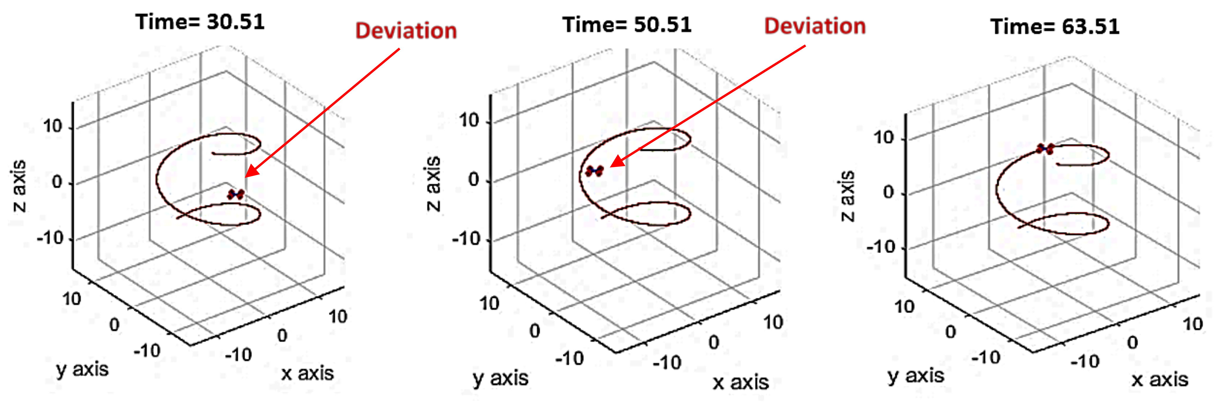
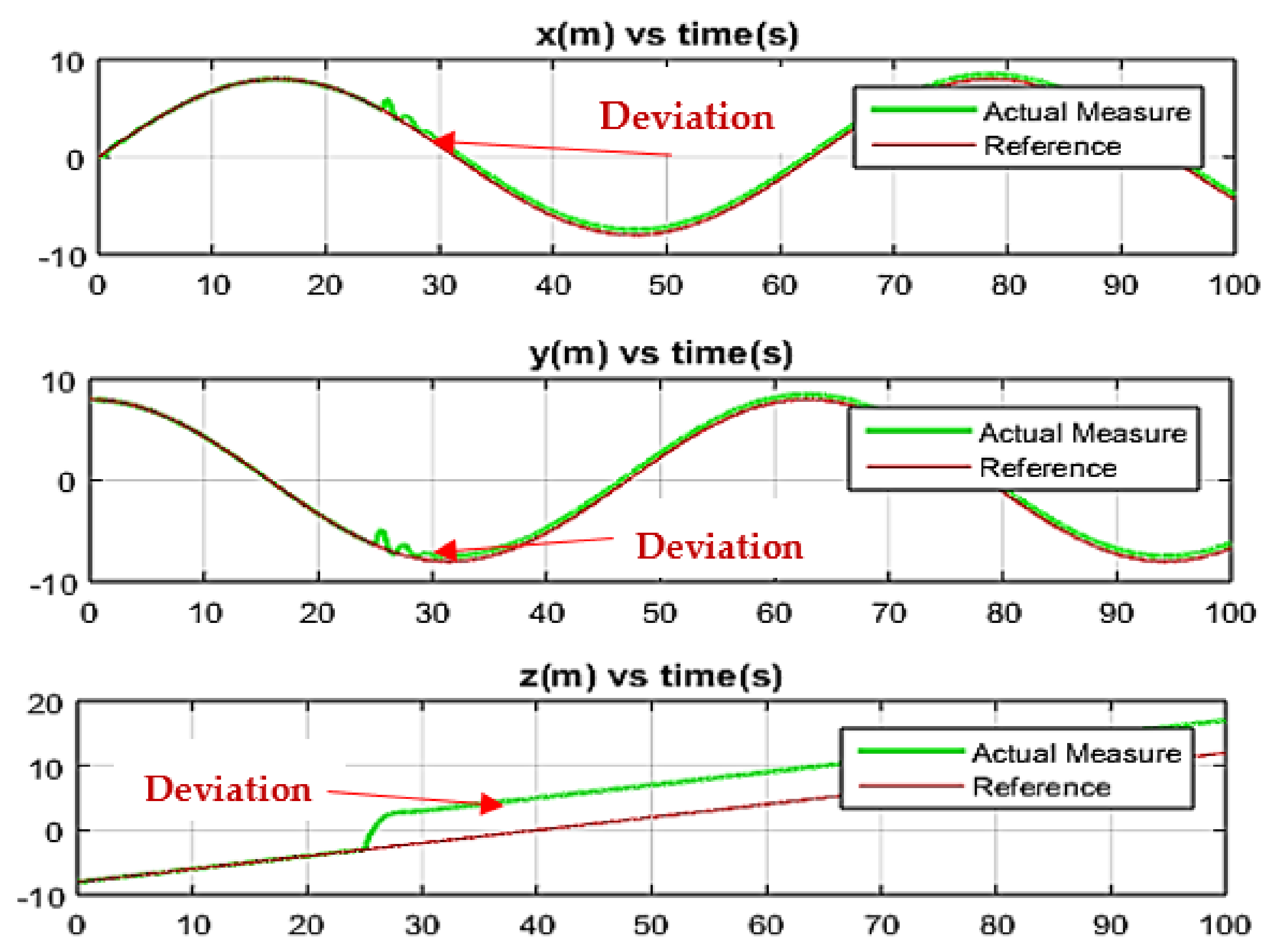
  • In addition to this, there are some algorithms such that nonlinear dynamic inversion estimator design [27,28] that also address the uncertainty via estimator designs. The limitation observed in such algorithm is quite serious and that is by increasing the magnitude of disturbance in the simulation, the quadrotor deviates from the track. For better observer design, it is better to consider the brushless DC motor dynamics into consideration because in this way one may have observer bandwidth to ensure the stability [29].
Thus, the above postulates motivated authors to come up with the technique that may resolve the above limitations without using any observer design and, after a detailed research background paper, proposes an option of a fuzzy based backstepping controller.
Fuzzy logic control has been amalgamated before with SMC for several applications such as NPS AUV II [30], pendulum-type overhead cranes [31], deep submergence rescue vehicle [32] and for the pantograph-Catenary system [33], and have so far produced better results but the chattering problem with slow convergence rates are still the limitations especially under the impact of unmodelled dynamic factors. This manuscript proposes the fuzzy logic based backstepping control design for an underactuated quadrotor unmanned aerial vehicle to track the helical trajectory with less steady state and transient issues even under the influence of lumped unmodelled dynamic factors. Moreover, the proposed technique provides a faster convergence rate to perform aggressive maneuvers. The main contributions of this research article are stated as below:
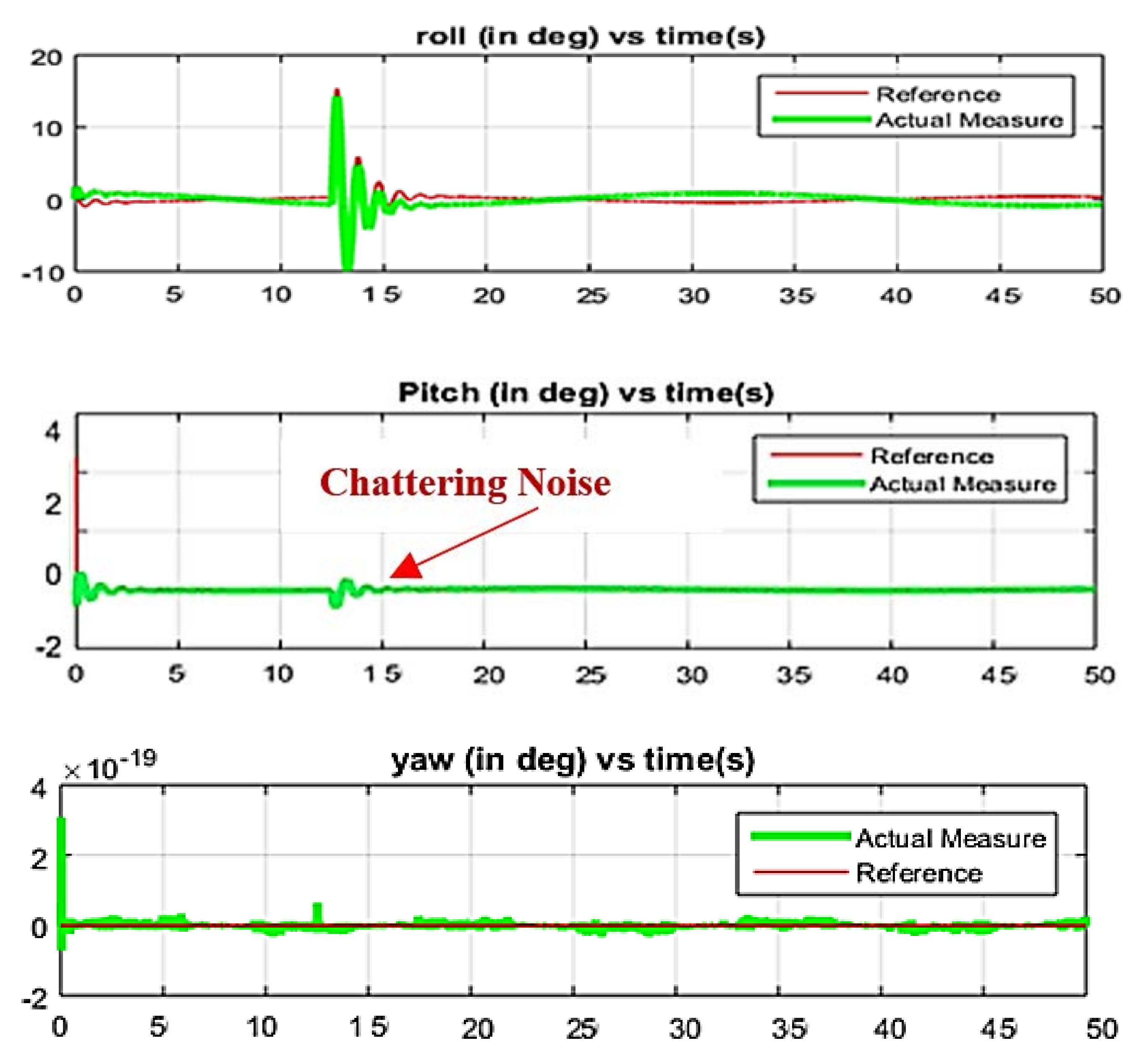
  • In comparison with the conventional backstepping control technique, it proposes the fuzzy based Backstepping control design that will take care of unmodelled dynamic factors and overcome the limitations such that chattering effect and enabling drone to do aggressive maneuvers;
  • Fuzzy logic control (FLC) design with the backstepping control design addresses the unmodelled dynamic factors and helical trajectory issues as compared to conventional BSC;
  • Moreover, the Lyapunov stability approach is also amalgamated with nonlinear fuzzy backstepping control design.
Our focus is to propose the backstepping method being hybridized with fuzzy logic control design and allowing the liberty for recursive control algorithm. This recursiveness will reduce the unmodelled dynamic effects in the quadrotor UAV nonlinear model. Thus, to execute this, the dynamic model of an underactuated quadrotor craft has been divided into four subsystems such that the yaw angle, pitch-x, roll-y and altitude as in [34]. This modelling approach considers the coupled nonlinear dynamics in the control inputs, and unknown unmodelled dynamics. With this technique, this paper addresses one of the solutions to resolve the constraints such as a chattering effect, enabling the quadrotor UAV to perform aggressive maneuvers with a faster convergence rate and less control input energy as compared to the fuzzy version of sliding mode control. This makes this research work as one of a kind.
The paper is divided into six sections such that the basic introduction and background can be studied under Section 1, whereas Section 2 discusses the problem formulation. The dynamic model is shown in Section 3 whereas the Section 4 presents the synthesis proof for fuzzy backstepping control in contrast with BSC design. One may find the simulation results with discussion in Section 5 and its correlation with conventional backstepping control (BSC). Last but certainly not least, a comprehensive conclusion is provided in Section 6.

2. Problem Formulation

This section presents the problem formulation along with the synthesis results. It should be noted that the input will be triangular membership functions and the output of fuzzy logic control (FLC) part will be singleton in nature based on center of gravity (CoG) as shown in Figure 1a,b respectively. The scale defined for all input and output membership functions are from −0.6 to +0.6. This fuzzy logic control is amalgamated with backstepping control design.
In the above figure, L s n   and   L 0 are defined as input error and rate of change of input error respectively. The rules are mentioned in Table 2.
Moreover, as per [19], a nonlinear system for proposing the backstepping control design is stated mathematically as:
η ˙ = f η + g η ξ
ξ ˙ = u + δ t , η ,
where η T ,   ξ T i + 1 is defined as a state, the term u is defined as the control input. Moreover, the below mentioned assumptions are supposed:
  • f : D n and g : D n are the known functions which are differentiable in domain D n . This contains η = 0 which is origin and moreover this will lead to f 0   = 0 .
  • The Equation (1) can be stabilized with this term as ξ = φ η which is a feedback state. It should be noted that in order to satisfy the Lyapunov function we must derive φ 0   = 0 , this will lead to:
    V η η f η + g η φ η W η , in this expression one may see the term W η defined as positive function, η D .
  • Moreover, the bounded matched vanishing perturbation function is given as δ t , 0   = 0 ,   δ t , η Δ ,   and   Δ > 0 .
The main goal is to design a control input u in a way that will ensure the closed loop stability of the origin denoted as η = 0 ,   ξ = 0 of system Equations (1) and (2) under the influence of unmodelled dynamic factors δ t , η . Once the control input is designed then the second task is to compute the control laws for every individual subsystem of our proposed underactuated quadrotor craft to show the stability for every subsystem.

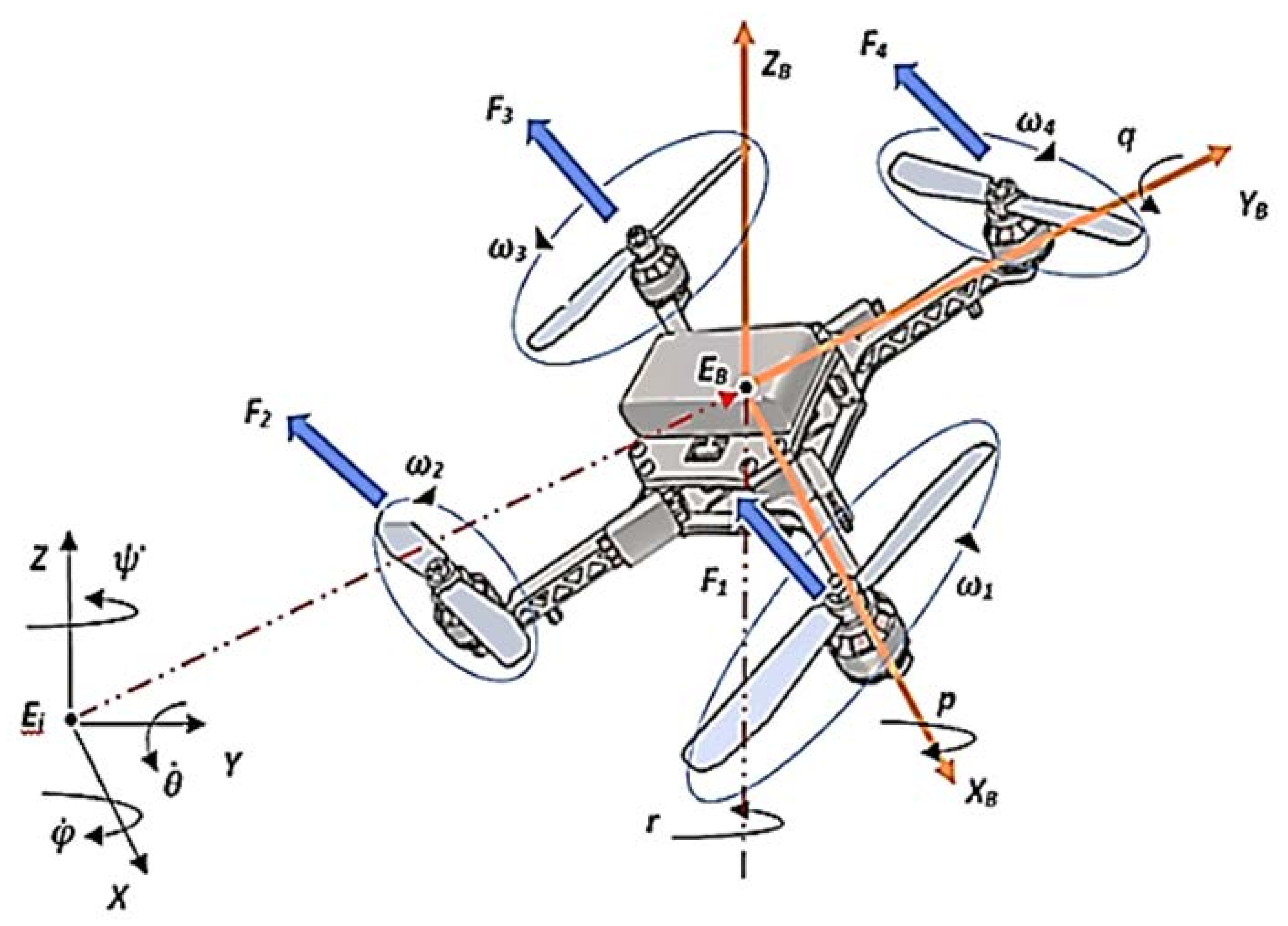
3. Dynamic Model of Underactuated Quadrotor UAV

An underactuated quadrotor unmanned aerial vehicle (UAV) is derived by demonstrating a solid body flying in a 3-Dimensional space and subjected to one force and three moments [6]. Moreover, the one may define the coordinates of the proposed quadrotor as x ,   y ,   z ,   ϕ ,   θ ,   ψ , where γ represents the relative position of the center of mass of the quadrotor with reference to inertial frame and is given as x ,   y ,   z this belongs to 3 .
The λ = ϕ ,   θ ,   ψ 3 are the Euler angles representing the roll, pitch and yaw. The moment of inertia with respect to x ,   y   and   z are given as I x ,   I y and I z . While mass is indicated by m , length of one arm is indicated by l and torques with respect to roll, pitch and yaw respectively are as τ ϕ ,   τ θ ,   τ ψ [30].
x ¨ = 1 m sin θ   u s
y ¨ = u s m cos θ   sin ϕ
z ¨ = cos θ sin ϕ m u s g
ϕ ¨ = θ ˙ ψ ˙ I y I z I x + l I x τ ϕ
θ ¨ = ϕ ˙ ψ ˙ I x I z I y + l I y τ θ
ψ ¨ = ϕ ˙ θ ˙ I y I x I z + l I z τ ψ .
In the above Equations (3)–(8) derived from Figure 2, u s can be considered a combined effect of all control inputs or motor thrust as both are directly proportional, m is the mass of quadrotor, g is the acceleration due to gravity whereas I x , I y and I z are the inertia along x ,   y and z axis. Moreover, the above dynamic model for an underactuated quadrotor unmanned aerial vehicle (UAV) considers the brushless DC (BLDC) motor’s dynamic as well as the flexibility of the blades as one of the coupled unmodelled dynamics in the control input and this mase control design a difficult task. As per the Newton’s law of momentum it is concluded that the axial velocity, that is, U of the individual actuators will be higher than the speed V through the air. Thus, the thrust of an actuator is equal to the air passing through it. The aerodynamic forces and moments can be derived as a relationship between the blade element theory and momentum. It is admitted that, by increasing the blades on the propellers, the maneuvering will be difficult, and it will affect the flight speed, using the knowledge of helicopter aerodynamics as these are similar conditions to quadrotor theory. Since the quadrotor has four motors with propellers, their co-efficient of non-dimensional power, torque and thrust can define the characteristics of a rotor as shown in below equations:
C t = T ρ A Ω R 2
C q = Q ρ A Ω R 2 R
C p = Q ρ A Ω R 3 .
In Equations (9)–(11), C t is the thrust co-efficient, T is termed the thrust itself, rotor shaft is given by Q , air density is ρ , A is an area of blade, Ω is the angular velocity and lastly, R is given as the radius of the blade. Moreover, the power and torque co-efficients are shown as:
P = Q Ω .
By substitution of power coefficients into Equation (10), one may get:
C p = C q = Q Ω ρ A Ω R 3 = Q Ω ρ A Ω R 2 R .
For maneuvering the quadrotor, there must be uniform inflow and therefore the constant drag profile co-efficient is taken as C d 0 = 0.0175 ; this is known as momentum modification theory based on approximation, where the σ term is the solidity ratio of rotor. This will triple the power induced in the maneuvering over the power of a profile as shown in Equation (14):
C p = K C t 2 × C t + 1 8 σ C d 0 .

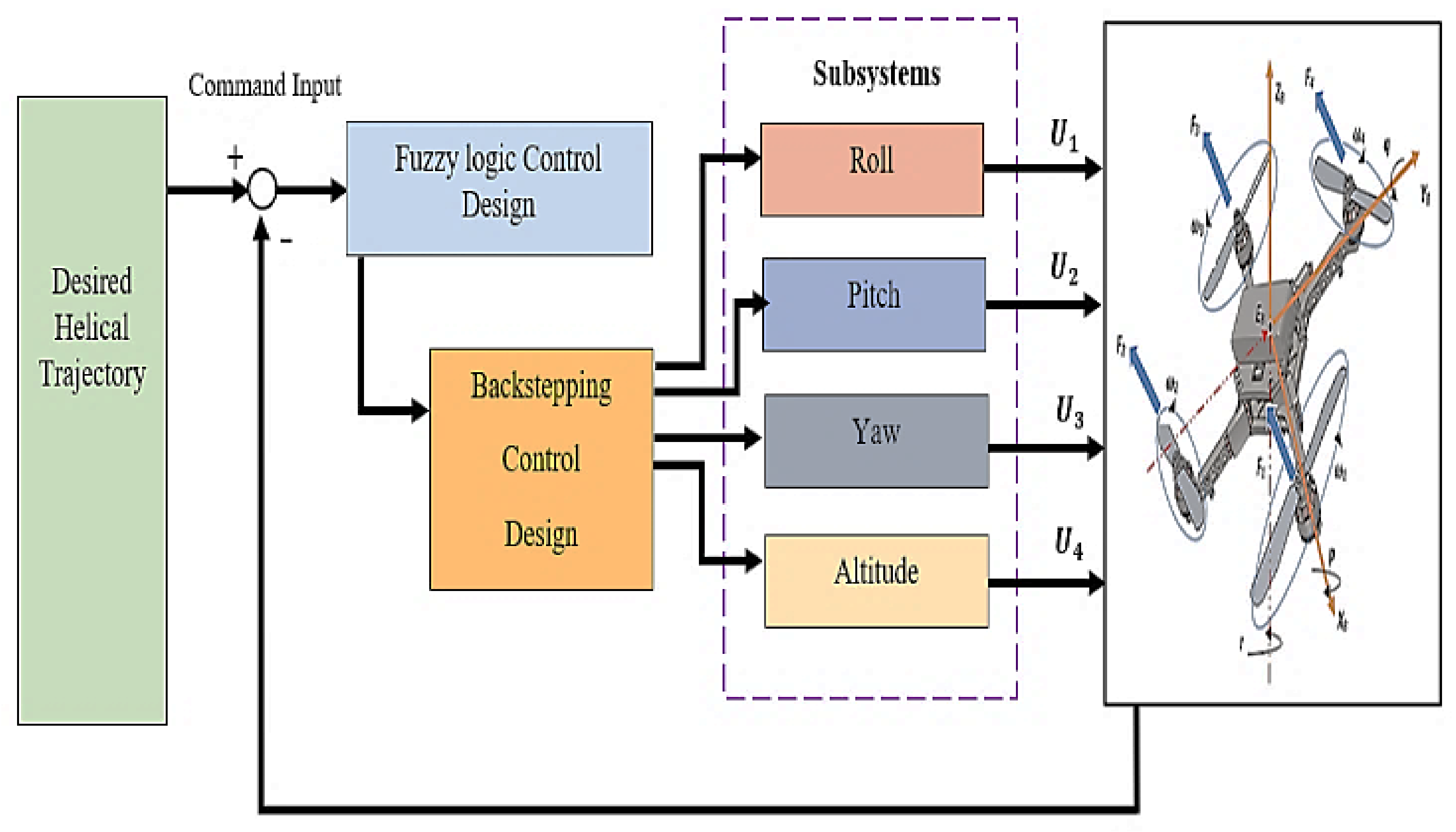
4. Fuzzy Based Backstepping Control Design with Synthesis Proof

This section distributed the dynamic model mentioned in section III into further subsystems, that is, altitude subsystem z , the roll subsystem y ϕ , pitch subsystem x θ and yaw subsystem ψ . After distributing main dynamics into subsystems, one may derive the adaptive robust stabilizing control design for each subsystem by using Theorem 1, along with the presence of unmodelled dynamic factors δ t ,   η as mentioned below:
Theorem 1.
Consider the system mentioned in Equations (1) and (2) under some of the assumptions a and b such that k > 0 , and for the Lyapunov stability function V 1 η , z ¯ = V η + 0.5 z ¯ 2 , where z ¯ = ξ φ η . This leads to control law for backstepping control as mentioned below:
u = φ η η f η + g η ξ V η η g η .
This leads to
u = k z ¯ s g n z ¯ Δ .
The feedback is generated and provided back to the fuzzy block where fuzzy regulates and generates the manipulated input u for backstepping control design. The entire block diagram can be seen in Figure 3.
Since backstepping control has chattering phenomena in the beginning, because of direct input provided in most of the cases, there is therefore a need to regulate the inputs smoothly and accurately so that these chattering phenomena can be eliminated easily. Once backstepping control will get the manipulated input it will drive the respective subsystems designed using the Simulink tool for roll, pitch, yaw, and altitude. These subsystems are designed using the dynamic model of underactuated quadrotor UAV. Realizing that backstepping control introduces the chattering effect in the beginning, hence, it is better to create a boundary layer around the control laws of backstepping control design and introduce the continuous control like fuzzy logic design within the boundary. In this way, one may deal with this issue.
This adaptive robust scheme stabilizes the system as per the mathematical proof mentioned below:
Mathematical Proof.
As per the basic concept of backstepping control technique, one may induct and deduct the term g η φ η at the right-hand side of Equation (1):
η ˙ = f η + g η φ η + g η ξ φ η
ξ ˙ = u + δ t , η .
One may derive f ¯ η as f η + g η φ η , z ¯ = ξ φ η and the derivative as: z ¯ ˙ = ξ ˙ φ ˙ η   =   u + δ t , η φ ˙ η . This brings the change in variable as shown below:
v ¯ = u φ ˙ η .
Moreover, the term φ ˙ η is defined as:
φ ˙ η   = φ η η η ˙ = φ η η f η + g n ξ .
In this way, the system proposed in Equation (17) can be expressed as conventional backstepping form:
η ˙ = f ¯ η + g η z ¯
z ¯ ˙ = v ¯ + δ t , η .
At the instant when z ¯ = 0 , this will guarantee that the proposed system in Equation (21) has an equilibrium point at origin as per the assumption b. This presents positive Lyapunov function, which is definite in nature and as V 1 η , z ¯   = V η + 0.5 z ¯ 2 . Moreover, the derivative along with the trajectory of (21) can be defined as:
V 1 ˙ η , z ¯ | 15 = V η η f ¯ η + V η η g η z ¯ + z ¯ z ¯ ˙ W η + V η η g η z ¯ + z ¯ z ¯ ˙ ,
where z ¯ ˙ = v ¯ + δ t , η can be re-arranged and after necessary substitution one may get:
v ¯ = k z ¯ V η η g η s g n z ¯ Δ .
In the above equation, one may take k > 0 ; by substituting this into previous equation one may get:
V 1 ˙ η , z ¯ | 15 W η k z ¯ 2 + z ¯ δ t , η z ¯ s g n z ¯   Δ .
By majorizing the term z ¯ δ t , η z ¯   δ t , η z ¯ δ t , η z ¯ Δ whereas, z ¯ z ¯ s g n z ¯ ; so in this way one may achieve z ¯ Δ = z ¯ s g n z ¯ Δ ; therefore replacing this in Equation (25):
V 1 ˙ η , z ¯ | 15 W η k z ¯ 2 < 0 .
In this way, the origin of Equation (21) can easily be stabilized. It is clear that φ 0   = 0 is an origin of the system (1) and (2). Moreover, the input equation u = v ¯ + φ ˙ η can be derived from Equation (20) and replacing (21) and (23).
Designing the altitude controller, the subsystem z defines the altitude dynamics of an underactuated quadrotor. The mathematical representation is given as:
z ¨ = cos θ   cos ϕ m u s g + δ η , t .
In Equation (25), δ η , t Δ 1 , moreover, defining the state variables as x 1 = z   and   x 2 = z ˙ and u s = m cos θ cos ϕ u z + g .
As per the methodology of backstepping control design [19], one may see x 2 = φ x 1   = α 6 x 1 ,   α 6 > 0 . In this way, the subsystem mentioned in Equation (27) can be re-written as:
x ˙ 1 = α 6 x 1
x ˙ 2 = u z + δ η , t .
The stabilizing control design for the subsystem mentioned in Equations (28) and (29) after solving for the Lyapunov function as V z x 1   = 1 2 x 1 2 followed by the result of Theorem 1, where ξ = x 2 ,   f η   = 0 ,   η = x 1 ,   g η   = 1   and   z ¯ = x 2 + α 6 x 1 ; can be designed as:
u z = 1 + k z α 6 x 1 α 6 + k z x 2 s g n x 2 + α 6 x 1 Δ 1 .
Continuing with the design for yaw controller, the dynamics is represented as:
ψ ¨ = ϕ ˙ θ ˙ B 1 + B 2 τ ψ + δ η , t .
In the above Equation (31) one may define B 1 = I y I x I z and B 2 = l I z and the term δ η , t Δ 2 . Where the terms I x ,   I y and I z are the inertial matrices and they describe x 3 = ψ and x 4 = ψ ˙ state variables and the torque produced as:
τ ψ = 1 B 2 ϕ θ ˙ B 1 + u ψ .
In this way, the Equation (32) will become as:
ψ ¨ = u ψ + δ η , t .
By adopting the same procedure as previously adopted for altitude, one may get x 4 = φ x 3   = α 7 x 3 where for α 7 > 0 , the yaw dynamics will be:
x ˙ 3 = α 7 x 3
x ˙ 4 = u ψ + δ η , t .
Similarly, the control design can be derived by solving the Lyapunov function as V ψ x 3   = 1 2 x 3 2 and defining the variables like ξ = x 4 ,   η = x 3 , f η   = 0 ,   g η   = 1 ,   z ¯ = x 4 + α 7 x 3 as:
u ψ = 1 + k ψ α 7 x 3 α 7 + k ψ x 4 s g n x 4 + α 7 x 3 Δ 2 .
The translational motion along x -axis and over the rotational displacement which is pitch angle θ around y -axis as:
x ¨ = 1 m sin θ u s
θ ¨ = θ ˙ ψ ˙ I x I z I y + l I y τ θ + δ η , t .
In the above equations defining B 3 = I x I z I y where u s 0 and B 4 = l I y . One may define the state variables as x 5 = x ,   x 6 = x ˙ ,   x 7 = θ   and   x 8 = θ ˙ . This will lead to the below mentioned state space representation as:
x 5 ˙ = x 6
x 6 ˙ = 1 m sin x 7 u s
x 7 ˙ = x 8
x 8 ˙ = ϕ ˙ ψ ˙ B 3 + B 4 τ θ + δ η , t .
Utilizing Equations (39) and (40), one may select the virtual input as shown below:
u 1 x = sin x 7   = m u s u x .
As per the methodology and fundamentals of backstepping control design [19] one may consider as x 6 = φ x 5   = α 5 x 5 for α 5 > 0 . Moreover, these equations can be re-written as mentioned below:
x ˙ 5 = α 5 x 5
x ˙ 6 = u x .
In the above Equation (45) the control input is derived as u x = 1 + α 5 k 5 x 5 α 5 + k 5 x 6 from Lyapunov function V 1 x 5   = 1 / 2   x 5 2 . Therefore, replacing u x in Equation (42) one may get:
u 1 x = m u s d 1 x 5 + d 2 x 6 ,
where the new terms, that is, d 1 = 1 + α 5 k 5 and d 2 = α 5 + k 5 . The next procedure is related to discuss the iterative method of backstepping by opting three Equations (38)–(41), this will lead to the subsystem be re-written as:
x 5 ˙ x 6 ˙   = x 6 0 + 0 u s m sin x 7 ,
where x 7 ˙ = x 8 = u 2 x , in this scenario, η = x 5 , x 6 T and ξ = x 7 . The improved backstepping control design proposed in [18] is then implemented for the system Equation (47) by considering the Lyapunov function as:
V 2 = V 2 x 5 , x 6   = 1 2 x 5 2 + β 1 2 x 6 + α 5 x 5 2 .
In this way the virtual input can be defined as u 1 x whereas φ 1 = φ 1 x 5 , x 6   = m u d 1 x 5 + d 2 x 6 by applying the proposition as mentioned in [18] one may derive u 2 x as:
u 2 x = φ 1 η f η + g η sin ξ V 2 η g η k 6 q 1 cos ξ .
The terms like φ 1 x 5 , x 6 x 5 = m u d 1 , ( φ 1 ( x 5 , x 6 ) ) x 6 = m u d 2 .
Similarly, ( V 2 x 5 , x 6 ) x 5 =   1 + β 1 α 5 2 x 5 + β 1 α 5 x 6 , ( V 2 x 5 , x 6 ) x 6 =   α 5 + 1 β 1 x 6 , Moreover, q 1 = sin ξ φ 1 . Hence the virtual input u 2 x is given as:
u 2 x =   k 6 m d 1 u s β 1 α 5 u s m ( cos x 7 ) 2 x 5 + m d 1 + k 6 m d 2 u s cos x 7 + u s β 1 m cos x 7 x 6 d 2 + k 6 tan x 7 .
In this way the entire state space matrix shown in the equations from (39) to (42) are taken with η = x 5 , x 6 , x 7 T with ξ = x 8 and for τ θ = 0.5 B 4 ϕ ˙ ψ ˙ B 3 + τ θ a can be written again as:
x 5 ˙ x 6 ˙ x 7 ˙   = x 6 u s m sin x 7 0 + 0 0 1 ,
whereas x ˙ 8 = τ θ a + δ η , t   = u 3 x + δ η , t . Moreover, the proposed Lyapunov function for this above system can be seen as:
V 3 = V 3 x 5 , x 6 ,   x 7   = 1 2 x 5 2 + β 1 2 x 6 + α 5 x 5 2 + β 2 2 sin x 7 m u s d 1 x 5 + d 2 x 6 ) 2 .
Similarly, the virtual input φ 2 is interlinked with u 2 x as shown in below Equation (53):
φ 2 = φ 2 x 5 , x 6 ,   x 7 =   k 6 m d 1 u s + u s β 1 α 5 m x 5 sec x 7 + k 6 m d 2 + m d 1 u s + u s β 1 m x 6 sec x 7 q 2 tan x 7 .
In Equation (53) the term d 2 + k 6 is equal to q 2 . Furthermore, as per the Theorem 1 stated before, the mathematical expression for the controller is given as:
u 3 x = k 7 z 3 V 3 η η g η s g n z 3 Δ 3 + φ 2 η η f η + g η ξ .
In the above equation for controller, the variable z 3 = x 8 φ 2 , k 7 > 0 ,   η = x 5 ,   x 6 , x 7 T ,   g η   = 0 ,   0 ,   1 T whereas
φ 2 x 5 =   k 6 m d 1 u s + u s β 1 α 5 m sec x 7
φ 2 x 6 =   m d 1 u s + k 6 m d 2 u s + u s β 1 m sec x 7
φ 2 x 7 =   m k 6 d 1 u s + u s β 1 α 5 m x 5 sec x 7 tan x 7 + m d 1 + k 6 d 2 u s + u s β 1 m x 6 sec x 7 tan x 7 d 2 + k 6 sec 2 x 7 .
Moreover,
V 3 x 7 = β 2 2 sin 2 x 7 β 2 m u s d 1 x 5 + d 2 x 6 cos x 7 .
This the reason, for which the input term u 3 x will be:
u 3 x = φ 2 x 5 x 6 φ 2 x 6 u s m sin x 7 + φ 2 x 7 x 8 V 3 x 7 k 7 x 8 φ 2 s g n x 8 φ 2 Δ 3 .
In same way, one may see the translational and rotational dynamics along the y axis and the roll ϕ are represented respectively as:
y ¨ = u s m cos θ sin ϕ
ϕ ¨ = θ ˙ ψ ˙ B 5 + B 6 τ ϕ + δ t , η .
Here, the variable B 5 = I y I z I x and B 6 = l I x hence defining the variables as x 9 = y ,   x 10 = y ˙ ,   x 11 = ϕ whereas x 12 = ϕ ˙ . This leads to the below mentioned state space representation:
x 9 ˙ = x 10
x 10 ˙ = cos x 7 m sin x 11 u s
x 11 ˙ = x 12
x 12 ˙ = ϕ ˙ ψ ˙ a 1 + a 2 τ ϕ + δ t , η .
Hence considering the first two Equations (62) and (63), one may derive the virtual input u y as:
u y = sin x 11 = m u s cos x 7 u 1 .
Thus, defining x 10 = φ x 9   = α 1 x 9 for the condition as α 1 > 0 ; moreover, the subsystem can be re-stated as x ˙ 9 = α 1 x 9 whereas x 10 ˙ = u 1 . The term V 1 x 9   = 1 / 2   x 9 2 is the Lyapunov function and as per the methodology of classical backstepping control, the input u 1 is defined as = u 1 k 1 α 1 + 1 x 9 k 1 + α 1 x 10 . This can be replaced with Equation (66) as:
u y = m u s cos x 7 b 1 x 9 b 2 x 10 .
In the above equation, the variable b 1 = k 1 α 1 + 1 ,   whereas   b 2 = k 1 + α 1 . Furthermore, the Equation (64) is added to derive the new subsystem as written with η = ξ = x 11 and x 9 , x 10 T :
x 9 ˙ x 10 ˙   = x 10 0 + 0 u s cos x 7 m sin x 11 ,
where x ˙ 11 = x 12 = u y 2 . Thus, deriving the similar procedure to previous subsystem with V 2 x 9 , x 10   = 1 2 x 9 2 + β 3 2 x 10 + α 1 x 9 2 and φ 1 = φ 1 x 9 , x 10   = m u s cos x 7 b 1 x 9 + b 2 x 10 . In this way, a similar control is obtained as given below:
u y 2 = m k 2 b 1 u s cos x 7 + β 3 α 1 u s cos x 7 m x 9 cos x 11 b 1 m u s cos x 7 + m k 2 b 2 u s cos x 7 + u s cos x 7 m x 10 cos x 11 ( b 2 + k 2 ) tan x 11 .
Finally, in the last step, subsystem for y   with   ϕ is fully taken into consideration with ξ = x 12 and η = x 9 , x 10 , x 11 T :
τ ϕ = 1 B 6 θ ˙ ψ ˙ B 5 + τ 1 .
Further one may re-write as mentioned below:
x ˙ 9 x ˙ 10 x ˙ 11   = x 10 cos x 7 sin x 11 u s m 0 + 0 0 1 x 12 ,
where x 12 ˙ = τ 1 + δ t , η and τ 1 = u y 3 , φ 2 is linked with u y 2 , as mentioned in the Equation (69). Moreover, the Lyapunov function is derived in same fashion as:
V 3 = V 3 x 9 , x 10 , x 11   = 1 2 x 9 2 + β 3 2 x 10 + α 1 x 9 2 + β 4 2 sin x 11 + m b 1 x 9 + b 2 x 10 u s cos x 7 2 .
Using Theorem 1, one may derive the input u y 3 as:
u y 3 = φ 2 x 9 x 10 + φ 2 x 10 u s m cos x 7 sin x 11 + φ 2 x 11 x 12 V 3 x 11 k 3 x 12 φ 2 s g n x 12 φ 2 Δ 4 ,
whereas,
φ 2 x 9 = k 2 m b 1 u s cos x 7 + u s β 3 α 1 cos x 7 m sec x 11
φ 2 x 10 = m b 1 u s cos x 7 + k 2 m b 2 u s cos x 7 sec x 11 u 3 β 3 cos x 7 m sec x 11
φ 2 x 11 = m b 1 + k 2 b 2 u s cos x 7 + u s β 3 cos x 7 m x 10 R 1 b 2 + k 2 sec 2 x 11 m k 2 b 1 u s cos x 7 + u s β 3 α 1 cos x 7 m x 9 R 1
V 3 x 11 = β 4 2 sin 2 x 11 + R 2 cos x 11 ,
where the terms R 1 and R 2 are defined as:
R 1 = sec x 11 tan x 11
R 2 = β 4 m u s cos x 7 b 1 x 9 + b 2 x 10 .
To simulate the effectiveness of proposed control technique, paper has simulated the Equations (27), (32) and (70) along with the equation τ θ = 0.5 B 4 ϕ ˙ ψ ˙ B 3 + τ θ a for trajectory tracking problem for an underactuated quadrotor UAV. The software used for the simulation is MATLAB & Simulink R2021a version. □

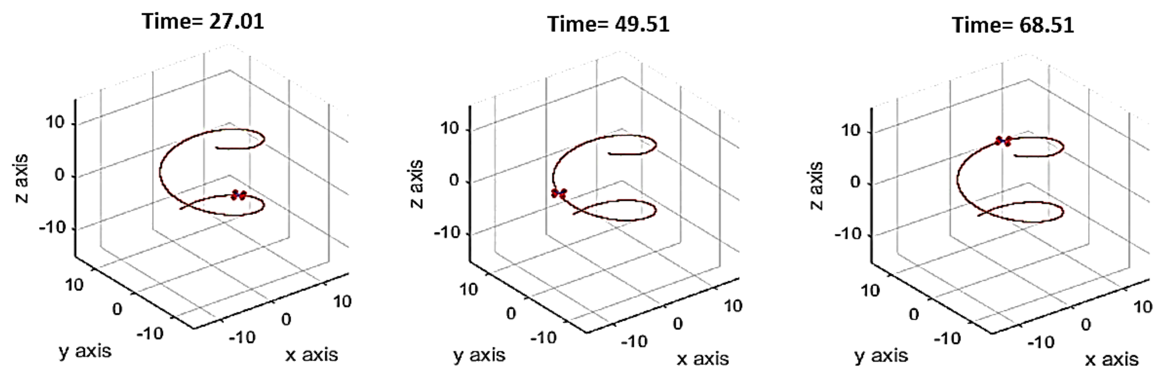
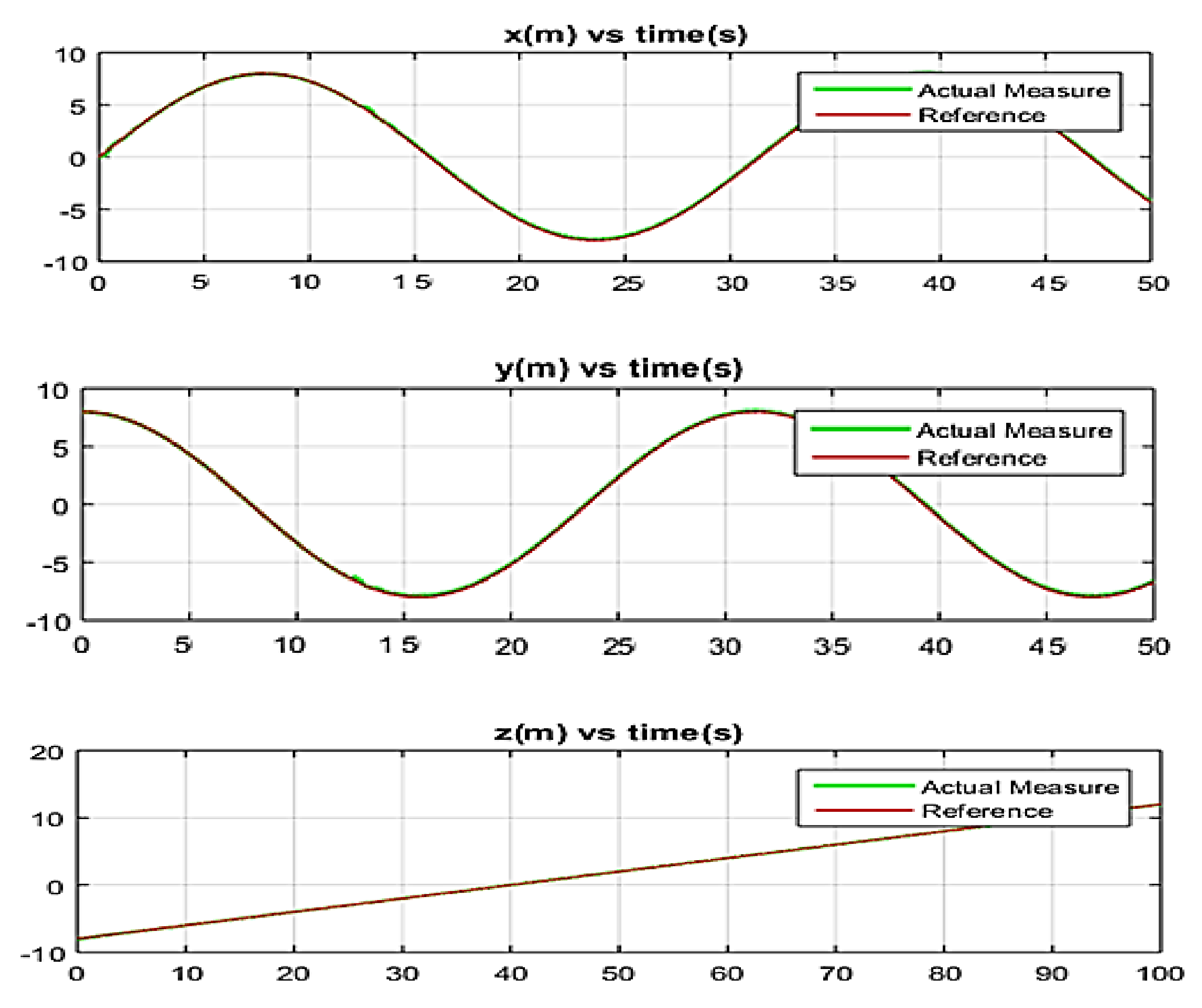
5. Simulation Results

In MATLAB & Simulink software, there is a differential equation solver function as ode45 which fix the sample time by-default as 0.01 second. For the dynamics of an underactuated quadrotor model, mass m = 0.8   kg , the distance from motor to the center of gravity CoG is termed as l = 0.35 m, whereas the acceleration due to gravity is given as g = 9.8   ms 2 lastly but certainly not the least are the moments of inertia along x ,   y and z axis i.e., I x = I y = 0.01656   kgm 2 and I z = 0.037255   kgm 2 . The gains in the Equations (21), (26) and (64) and in τ θ = 0.5 B 4 ϕ ˙ ψ ˙ B 3 + τ θ a are mentioned in the Table 3.
For performance analysis, helical trajectory has been proposed for this work. To show the comparison, paper demonstrates the simulation results in between conventional backstepping control strategy and fuzzy based backstepping control. Firstly, the proposed underactuated quadrotor craft fly under nominal conditions without any disturbance and in second phase the unmodelled dynamic factors are added. This disturbance or unmodelled dynamic factor is in the form of a sine wave with an amplitude of 1.5 m and frequency is 1 rad / s . The results are demonstrated in Figure 4, Figure 5 and Figure 6 being controlled by Backstepping control with no disturbances.
When the unmodelled dynamic factor in the form of sine function is added into the system. The positional and angular velocities, that is, roll, pitch and yaw are no longer same. Moreover, the trajectory tracking is also having some deviation. These changes can be experienced in Figure 7, Figure 8 and Figure 9.
In Figure 7, one may see the underactuated quadrotor starts deviating from helical trajectory at 30th second whereas it again returns to trajectory at 64th second. One may see the deviation in positional responses as well using Figure 8. The angular quantities are simulated and are shown in Figure 9.
By adding the disturbance, one may see the deviation in Figure 8, and there is still chattering noise which is visible in Figure 9. The paper proposes the fuzzy based backstepping control technique to reduce these issues.
After executing the fuzzy based backstepping control, the trajectory response is restored. The deviation is noted in Figure 10 where the positional graphs are also restored to better state as shown in Figure 11. One may also witness the rotational responses in Figure 12, the chattering noise is still there in the angular graphs, that is, roll, pitch, and yaw. In this proposed technique, small errors are experienced during the trajectory tracking without under unmodelled dynamic factors. To prove that the proposed algorithm is more efficient, one may derive the control input energy (CIE) of both techniques as shown in Table 4 and Table 5. Remember that the robust backstepping control includes the sign function; however, it has been shown in [17] that the quadrotor’s dynamics are slower than those encountered by switching methods.
From Table 4 and Table 5, it has been shown that the fuzzy based backstepping controller outperforms the conventional backstepping control in the presence of unmodelled dynamic factors. Moreover, the control inputs with and without external disturbances are shown below in Figure 13.

Performance Evaluation over Another Trajectory

To check the robustness of the proposed algorithm, this paper presents one more trajectory tracking along with their responses for positional vectors. One can see this tracking performance illustrated in Figure 14. Their linear responses over the circular trajectory are shown in Figure 15:
The proposed algorithm titled as a fuzzy based backstepping control design not only works fine with the helical trajectory but also provides robust results for the circular trajectory as well, as shown in Figure 13 and Figure 14 respectively.

6. Conclusions

The paper shares an important concern of unmodelled dynamic factors and external disturbances for an underactuated quadrotor unmanned aerial vehicle (UAV). In addition to this, it shares related concerns of all robust, adaptive, and adaptive-robust techniques. The focus is set on the state-of-the-art approaches which are mostly adaptive-robust techniques. Discussing these limitations, the manuscript shares that the most frequent issue with these already proposed techniques—either robust, adaptive or hybrid versions of both approaches—is the sinusoidal functions in the subsystems of roll and pitch that limit our virtual input. Moreover, these already proposed algorithms do not focus on the Zeno effect (high number of oscillations on Brushless dc motors). This Zeno or chattering effect occurs in most of the aggressive maneuvers. Thus, a novel recursive and nonlinear fuzzy based backstepping control (FBSC) technique is proposed. The results of the proposed FBSC are correlated with the conventional BSC technique to address the issues, that is, Zeno effect, slow convergence rate, unnecessary time delays, and some serious issues related to transient and steady state responses.
The fuzzy logic controller (FLC) has been utilized with different robust schemes and has improved several performance factors. Thus, keeping the same intelligent hypothesis, paper proposes a merge of Fuzzy logic controller with backstepping control technique where the sub-control system designs are proposed for each state variable. Furthermore, the stability of proposed algorithm is also demonstrated using Lyapunov Stability criteria. As per the results of FBSC and correlation with the conventional backstepping control technique under the influence of unmodelled dynamic factors, one may conclude that FBSC outperforms BSC. The overall chattering phenomena is reduced in both simulations as compared with other control techniques as quoted by other researchers. Since the chattering phenomena are available in both algorithms, the paper therefore calculates the integral absolute error (IAE) for both algorithms and it is observed that the fuzzy based backstepping control algorithm approach produces the less integral absolute error. With these perks, the proposed algorithm is more suitable and one of its kind that can be proposed for unmanned aerial vehicles to have a stable flight even under the impact of unmodelled dynamics and external disturbances.
The future work is now focused on some extensive nonlinear extended state observers and disturbance observers with this same approach to reduce the time delay in accelerations to improve the maneuverability in the presence of unmodelled dynamic factors and external disturbances. In addition to this, some of the quantitative analysis work will also be dedicated to evaluating the error rates while executing more simulation work using the MATLAB UAV Toolbox to provide further validation by correlating other control algorithms as well. Moreover, the experimental setup will also be proposed to perform later once the robust performance is acquired via simulation results.

Author Contributions

Conceptualization, G.E.M.A. and S.A.B.M.Z.; methodology, G.E.M.A. and Z.A.A.; software, G.E.M.A.; validation, V.S.A., G.E.M.A. and B.S.C.; formal analysis, B.S.C.; investigation, G.E.M.A.; resources, S.A.B.M.Z.; writing—original draft preparation, G.E.M.A.; writing—review and editing, S.A.B.M.Z. and Z.A.A.; visualization, V.S.A. and B.S.C.; supervision, S.A.B.M.Z.; project administration, G.E.M.A.; funding acquisition, S.A.B.M.Z. All authors have read and agreed to the published version of the manuscript.

Funding

This research was funded by Yayasan Universiti Teknologi PETRONAS (YUTP) Funds, grant number 015CL0-316.

Acknowledgments

The author wishes to extend his sincere thanks to the support of Centre of Graduate Studies, Universiti Teknologi, PETRONAS, Malaysia for providing the state-of-the-art research facilities to carry on this work. Indeed, grateful for providing an opportunity to work as graduate research assistantship scheme to pursue my doctoral studies at the department of electrical and electronic engineering and under Yayasan Universiti Teknologi PETRONAS (YUTP) Funding, grant number 015CL0-316. In addition to this, the author is also thankful for the support provided by the collaborators from Condition Monitoring System, National Centre of Robotics and Automation, Mehran University of Engineering and Technology, Jamshoro, Sindh Pakistan.

Conflicts of Interest

The authors declare no conflict of interest.

References

  1. Thanh, H.L.N.N.; Hong, S.K. Quadcopter robust adaptive second order sliding mode control based on PID sliding surface. IEEE Access 2018, 6, 66850–66860. [Google Scholar] [CrossRef]
  2. Ononiwu, G.; Onojo, O.; Ozioko, O.; Nosiri, O. Quadcopter design for payload delivery. J. Comput. Commun. 2016, 4, 1–12. [Google Scholar] [CrossRef] [Green Version]
  3. Duggal, V.; Sukhwani, M.; Bipin, K.; Reddy, G.S.; Krishna, K.M. Plantation monitoring and yield estimation using autonomous quadcopter for precision agriculture. In Proceedings of the 2016 IEEE International Conference on Robotics and Automation (ICRA): Stockholm, Sweden, 16–21 May 2016; pp. 5121–5127. [Google Scholar]
  4. Mogili, U.R.; Deepak, B.B.V.L. Review on application of drone systems in precision agriculture. Procedia Comput. Sci. 2018, 133, 502–509. [Google Scholar] [CrossRef]
  5. Kuantama, E.; Tarca, R.; Dzitac, S.; Dzitac, I.; Vesselenyi, T.; Tarca, I. The design and experimental development of air scanning using a sniffer Quadcopter. Sensors 2019, 19, 3849. [Google Scholar] [CrossRef] [PubMed] [Green Version]
  6. Castillo, P.; Munoz, L.E.; Santos, O. Robust control algorithm for a rotorcraft disturbed by crosswind. IEEE Trans. Aerosp. Electron. Syst. 2014, 50, 756–763. [Google Scholar] [CrossRef]
  7. Bouabdallah, S.; Siegwart, R. Backstepping and sliding-mode techniques applied to an indoor micro quadrotor. In Proceedings of the International Conference on Robotics and Automation, Barcelona, Spain, 18–22 April 2005; p. 2247. [Google Scholar]
  8. Ramirez-Rodriguez, H.; Parra-Vega, V.; Sanchez-Orta, A.; Garcia-Salazar, O. Robust backstepping control based on integral sliding modes for tracking of quadrotors. J. Intell. Robot. Syst. 2014, 73, 51–66. [Google Scholar] [CrossRef]
  9. Peng, C.; Bai, Y.; Gong, X.; Gao, Q.; Zhao, C.; Tian, Y. Modeling and robust backstepping sliding mode control with Adaptive RBFNN for a novel coaxial eight-rotor UAV. IEEE/CAA J. Autom. Sin. 2015, 2, 56–64. [Google Scholar]
  10. Zhao, Y.; Sun, X.; Wang, G.; Fan, Y. Adaptive Backstepping Sliding Mode Tracking Control for Underactuated Unmanned Surface Vehicle with Disturbances and Input Saturation. IEEE Access 2021, 9, 1304–1312. [Google Scholar] [CrossRef]
  11. Kim, N.S.; Kuc, T.Y. Sliding Mode Backstepping Control for Variable Mass Hexa-Rotor UAV. In Proceedings of the 2020 20th International Conference on Control, Automation and Systems (ICCAS), Busan, Koreapp, 13–16 October 2020; pp. 873–878. [Google Scholar]
  12. Abro, G.E.M.; Asirvadam, V.S.; Zulkifli, S.A. Single-Input Fuzzy-Sliding Mode Control for an Underactuated Quadrotor Craft. In Proceedings of the 2020 IEEE 2nd International Conference on Artificial Intelligence in Engineering and Technology (IICAIET), Kota Kinabalu, Malaysia, 26–27 September 2020; pp. 1–6. [Google Scholar]
  13. Abro, G.E.M.; Zulkifli, S.A.; Asirvadam, V.S.; Ali, Z.A. Model-Free-Based Single-Dimension Fuzzy SMC Design for Underactuated Quadrotor UAV. In Actuators; Multidisciplinary Digital Publishing Institute: Basel, Switzerland, 2021; Volume 10, p. 191. [Google Scholar]
  14. Cabecinhas, D.; Cunha, R.; Silvestre, C. A nonlinear quadrotor trajectory tracking controller with disturbance rejection. Control. Eng. Pract. 2014, 26, 1–10. [Google Scholar] [CrossRef]
  15. El-Badawy, A.A.A.; Rashad, R. Active anti-disturbance control of a quadrotor unmanned aerial vehicle using the command-filtering backstepping approach. Nonlinear Dyn. 2017, 90, 581–597. [Google Scholar]
  16. Zhang, L.Y.; Li, P. Full control of a quadrotor using parameter-scheduled backstepping method: Implementation and experimental tests. Nonlinear Dyn. 2017, 89, 1259–1278. [Google Scholar]
  17. Mokhtari, M.R.; Cherki, B. A new robust control for minirotorcraft unmanned aerial vehicles. ISA Trans. 2015, 56, 86–101. [Google Scholar] [CrossRef]
  18. García, O.; Ordaz, P.; Santos-Sánchez, O.-J.; Salazar, S.; Lozano, R. Backstepping and Robust Control for a Quadrotor in Outdoors Environments: An Experimental Approach. IEEE Access 2019, 7, 40635–40648. [Google Scholar] [CrossRef]
  19. Khalil, H.K. Nonlinear Systems, 2nd ed.; Prentice Hall: Hoboken, NJ, USA, 1996. [Google Scholar]
  20. Liu, H.; Xi, J.; Zhong, Y. Robust attitude stabilization for nonlinear quadrotor systems with uncertainties and delays. IEEE Trans. Ind. Electron. 2017, 64, 5585–5594. [Google Scholar] [CrossRef]
  21. Dydek, Z.T.; Annaswamy, A.M.; Lavretsky, E. Adaptive control of quadrotor UAVs: A design trade study with flight evaluations. IEEE Trans. Control Syst. Technol. 2012, 21, 1400–1406. [Google Scholar] [CrossRef]
  22. Dierks, T.; Jagannathan, S. Output feedback control of a quadrotor UAV using neural networks. IEEE Trans. Neural Netw. 2009, 21, 50–66. [Google Scholar] [CrossRef] [PubMed]
  23. Santos, M.; Lopez, V.; Morata, F. Intelligent fuzzy controller of a quadrotor. In Proceedings of the 2010 IEEE International Conference on Intelligent Systems and Knowledge Engineering, Hangzhou, China, 15–16 November 2010; pp. 141–146. [Google Scholar]
  24. Kayacan, E.; Maslim, R. Type-2 fuzzy logic trajectory tracking control of quadrotor VTOL aircraft with elliptic membership functions. IEEE/ASME Trans. Mechatron. 2016, 22, 339–348. [Google Scholar] [CrossRef]
  25. Mustafa, A.G.E.; Asirvadam, V.S.; Zulkifli, S.A.B.M.; Sattar, A.; Kumar, D.; Anwer, A. Effects of unmodelled dynamic factors on an under-actuated quadrotor: A review of hybrid observer design methods. Measurement and Control. 2020, 53, 1978–1987. [Google Scholar]
  26. Qi, Y.; Zhu, Y.; Wang, J.; Shan, J.; Liu, H.H.T. MUDE-based control of quadrotor for accurate attitude tracking. Control Eng. Pract. 2021, 108, 104721. [Google Scholar] [CrossRef]
  27. Dhadekar, D.D.; Sanghani, P.D.; Mangrulkar, K.K.; Talole, S.E. Robust control of quadrotor using uncertainty and disturbance estimation. J. Intell. Robot. Syst. 2021, 101, 1–21. [Google Scholar] [CrossRef]
  28. Castillo, A.; Sanz, R.; Garcia, P.; Qiu, W.; Wang, H.; Xu, C. Disturbance observer-based quadrotor attitude tracking control for aggressive maneuvers. Control Eng. Pract. 2019, 82, 14–23. [Google Scholar] [CrossRef]
  29. Sanz, R.; Garcia, P.; Zhong, Q.; Albertos, P. Robust control of quadrotors based on an uncertainty and disturbance estimator. J. Dyn. Syst. Meas. Control 2016, 138, 8. [Google Scholar] [CrossRef]
  30. Tiwari, N.K.; Waghmare, L.M.; Krishnankutty, P. Single input fuzzy logic controller tuning for steering control of autonomous underwater vehicle: Genetic algorithm approach. In Proceedings of the 2016 Indian Control Conference (ICC), Hyderabad, India, 4–6 January 2016; pp. 335–340. [Google Scholar]
  31. Ahmad, A.M.; Saealal, M.S.; Ismail, R.M.T.R.; Zawawi, M.A.; Nasir, A.N.K.; Ramli, M.S. Single input fuzzy controller with command shaping schemes for double-pendulum-type overhead crane. In AIP Conference Proceedings; American Institute of Physics: College Park, MD, USA, 2011; Volume 1337, no. 1; pp. 113–117. [Google Scholar]
  32. Ishaque, K.; Abdullah, S.S.; Ayob, S.M.; Salam, Z. A simplified approach to design fuzzy logic controller for an underwater vehicle. Ocean. Eng. 2011, 38, 271–284. [Google Scholar] [CrossRef]
  33. Farhan, F.M.; Shukor, N.S.A.; Ahmad, M.A.; Suid, M.H.; Ghazali, M.R.; Jusof, M.F.M. A simplify fuzzy logic controller design based safe experimentation dynamics for Pantograph-Cateary system. Indones. J. Electr. Eng. Comput. Sci. 2019, 14, 903–911. [Google Scholar] [CrossRef]
  34. Lozano, R. (Ed.) Unmanned Aerial Vehicles: Embedded Control; John Wiley & Sons: Hoboken, NJ, USA, 2013. [Google Scholar]
Figure 1. (a) Triangular Input and (b) Singleton CoG based Output membership functions.
Electronics 11 00999 g001
Figure 2. Physical Model of an Underactuated Quadrotor UAV.
Electronics 11 00999 g002
Figure 3. Proposed Fuzzy based Backstepping Control Diagram.
Electronics 11 00999 g003
Figure 4. Helical trajectory tracking using Backstepping control under no disturbances.
Electronics 11 00999 g004
Figure 5. Positional Responses by Backstepping Control under no disturbances.
Electronics 11 00999 g005
Figure 6. Roll, pitch, and Yaw Responses by Backstepping Control under no disturbances.
Electronics 11 00999 g006
Figure 7. Helical trajectory tracking using Backstepping control under unmodelled dynamics and external disturbance.
Electronics 11 00999 g007
Figure 8. Positional responses using Backstepping control under unmodelled dynamics and external disturbances.
Electronics 11 00999 g008
Figure 9. Roll, pitch, and yaw responses using Backstepping control under unmodelled dynamics and external disturbances.
Electronics 11 00999 g009
Figure 10. Helical trajectory tracking using Fuzzy based Backstepping control under unmodelled dynamic factors and external disturbances.
Electronics 11 00999 g010
Figure 11. Positional responses using Fuzzy based Backstepping control under unmodelled dynamics and external disturbances.
Electronics 11 00999 g011
Figure 12. Roll, pitch and yaw responses using Fuzzy based Backstepping control under unmodelled dynamics and external disturbances.
Electronics 11 00999 g012
Figure 13. (a) Control Input without Disturbances and (b) Control Input with Disturbances.
Electronics 11 00999 g013aElectronics 11 00999 g013b
Figure 14. Performance of Proposed algorithm over circular trajectory.
Electronics 11 00999 g014
Figure 15. Linear velocity responses while circular trajectory tracking.
Electronics 11 00999 g015
Table 1. State of the Art Approaches with limitations.
S. No.TechniqueLimitations
1Nonlinear Robust control design with Lyapunov Function [6].Proposed for bounded unmodelled dynamic factors but here are some time delays.
2Backstepping control design with sliding mode control [7]Proposed for the exponential unmodelled dynamic factors but has low convergence rate.
3Robust Backstepping control based on integral sliding modes (SMC) [8]It has an integral term that introduces overshoot sometimes when payload drops.
Moreover, SMC is sensitive to Zeno effect.
4Adaptive Neural network based backstepping Sliding mode control [9]This algorithm increases the settling time and processing time as well. This is one of the reasons that may lead to expensive hardware.
5Backstepping with sliding mode control with input saturation [10,11]Having low convergence rate and chattering effect is observed at some of the time instants.
6Fuzzy based Sliding mode control (FSMC) [12]Low convergence rate and sluggish maneuvers. In addition to this chattering effect is observed.
7Model free approach based Single dimension based FSMC [13] Acceleration delay is observed.
8Adaptive Nonlinear Backstepping control design [14]Limited to only constant and time varying disturbances.
9Nonlinear adaptive Backstepping control scheme for small UAVs [16,17]Limited to only bounded variations in dynamics.
10Nonlinear backstepping control with Sliding mode control technique [18,19] for multirotor craftsIt limits the virtual input because of sinusoidal functions with roll and pitch subsystems.
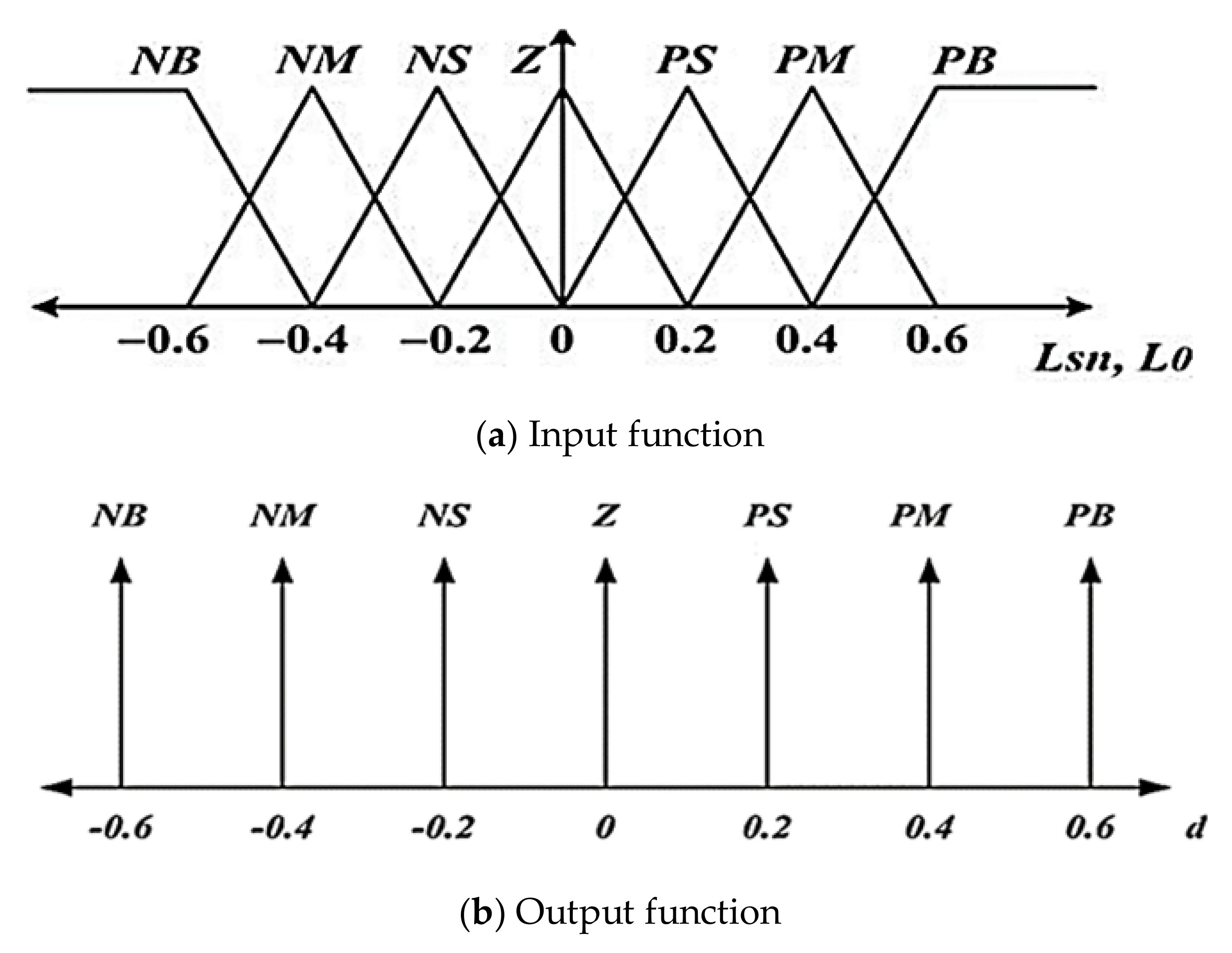
Table 2. Rules for Vectoral Distances.
LsnNBNSNSZPSNSPB
L0
PBZPSPMPBPBPBPB
NSNSZPSPMPBPBPB
PSNMNSZPSPMPBPB
ZNBNMNSZPSPMPB
NSNBNBNMNSZPSPM
NSNBNBNBNMNSZPS
NBNBNBNBNBNBNSZ
PB: Positive Big; PS: Positive Small; NB: Negative Big; NS: Negative Small; PM: Positive Medium; Z: Zero; NM: Negative Medium.
Table 3. Values of Gains for the Prescribed Sub-systems.
Sub-Systems
ψ z x θ y φ
Δ 1 = 34.6 Δ 2 = 3.6 Δ 3 = 25 Δ 4 = 34.6
α 7 = 13.5 α 6 = 14.6 α 5 = 0.245 α 1 = 1.45
k φ = 65.4 k z = 1 k 5 = 0.154 k 1 = 0.5
k 6 = 0.245 k 2 = 0.7
k 7 = 1.4 α 1 = 1.67
β 1 = 0.5 β 3 = 0.8
β 2 = 0.7 β 4 = 0.5
Table 4. Integral Absolute Error Values without Disturbances.
IndicatorBackstepping Control (BSC)Fuzzy Based Backstepping Control (FBSC)
I x a b s 1566.2%10,135%
I y a b s 287.34%1618.5%
I z a b s 288.77%64.43%
Table 5. Integral Absolute Error Values with Disturbances.
IndicatorBackstepping Control (BSC)Fuzzy Based Backstepping Control (FBSC)
I x a b s 10,386%9866.3%
I y a b s 9146.6%1680.7%
I z a b s 5988.5%64.85%
Publisher’s Note: MDPI stays neutral with regard to jurisdictional claims in published maps and institutional affiliations.

